Instruction Manual/Instrucciones
Questions?/¿Preguntas? 1-800-334-6871 [email protected]
1
4. Remove access cover (D) from parts bag.
5. Install the first conduit connector and conduit
(sold separately) into the access cover (D).
6. Feed supply wires into conduit and make wiring
connections as described in “Wiring Your Fixture”.
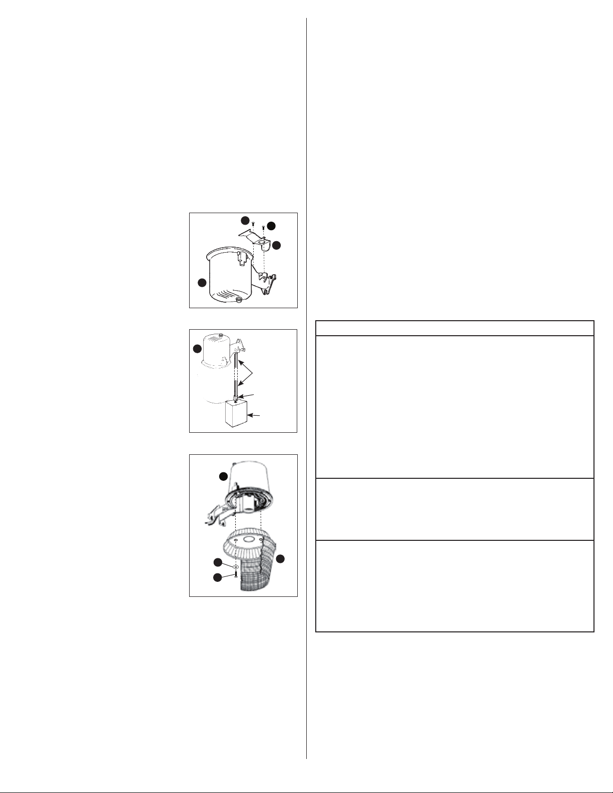
7. Attach access cover (D) to the light fixture (A)
using the two access cover mounting screws (F)
provided (Fig. 1).
NOTE: Make sure all wiring is placed into the arm
prior to tightening the access cover screws (F).
8. Using the three mounting screws (E) provided, bolt
the housing (A) to the mounting surface.
9. Connect second conduit and conduit connector at
the junction box (Fig. 2).
10. Fasten lens assembly (B) to housing (A) using the
two lens assembly lock screws (G) and two washers
(I) provided (Fig. 3).
WIRING YOUR FIXTURE
1. Turn off the power at the main fuse/breaker box.
2. Attach ground wire that is attached to fixture
housing (A) to the junction box earth ground wire.
3. Connect the black fixture wire to the black supply
wire (hot). Attach UL approved wire connector
(sold separately).
4. Connect the white fixture wire to the white supply
wire (neutral). Attach UL approved wire connector
(sold separately).
NOTE: Be careful to connect the wires correctly. Make
sure no bare strands of wire extend from the wire nut or
other approved wire connectors (sold separately).
INSTALLING THE BULB
1. Screw the bulb (C) securely into socket.
2. Back the bulb (C) out one or two turns, then screw
bulb (C) back to insure proper position in socket.
3. Turn power back ON.
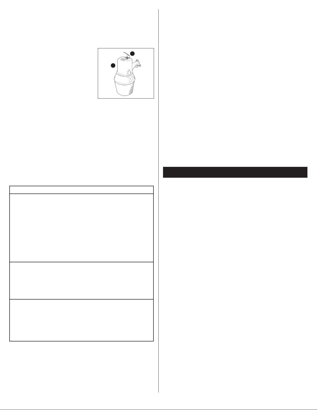
INSTALLING THE OPTIONAL LIGHT SHIELD/
REFLECTOR
NOTE: Sometimes fixtures are installed in locations
that receive too much reflected light. The photo sensor
may have trouble telling the difference between daylight
and light from the fixture. Also, if the fixture is in a
shadowy location, it may think it is always night time.
The light shield/reflector can be used to block or
channel light to the photo sensor.
PACKAGING CONTENTS/CONTENIDO DEL PAQUETE
ITEMS REQUIRED
(Purchase separately)
• Phillips screwdriver
• Adjustable wrench
• Drill with 3/16 in. drill bit
• 1/2 in. diameter flexible conduit (if applicable, length depends on application)
• 1/2 in. watertight conduit connectors (if applicable)
• Wire connectors
WARNINGS AND CAUTIONS
• Read these instructions.
• Keep these instructions.
• Heed all warnings.
• Follow all instructions.
• For outdoor use only.
• cULus LISTED for wet location use.
• Connect fixture to a 120 volt, 60 Hz power source. Any other connection voids the warranty.
• Fixture should be installed by persons with experience in household wiring or by a qualified
electrician. The electrical system, and the method of electrically connecting the fixture to it,
must be in accordance with the National Electrical Code and local building codes.
• Always use same wattage and type of bulb that was included with the fixture. Failure to do
so will void the warranty. See fixture for wattage.
• Disconnect at fuse or circuit breaker before installing or servicing.
• Disconnect power and allow fixture to cool before changing bulb or handling fixture.
• Edges may cut. Handle with care.
• Upside down installation can result in overheating or accumulation of water in fixture.
Install right side up.
• MINIMUM 90° C SUPPLY CONDUCTORS.
Notice: Lamps contain mercury, dispose according to local, state, or federal laws. For
more information, visit: www.lamprecycle.org.
MOUNTING YOUR FIXTURE
NOTE: This fixture is intended to be conduit connected to a properly installed and properly
grounded metal weatherproof junction box (not included). All conduit connectors, conduit, and
junction boxes (sold separately) should be UL Listed suitable for wet locations.
1. Using the pattern on the box, mark and drill holes for mounting.
NOTE: Mount this fixture in an upright position.
2. Install the two bottom mounting screws (E) first, leaving enough room between the
mounting screws and the mounting surface to accommodate mounting the fixture.
3. Screw the top mounting screw (E) into the predrilled hole and back the screw out. This
will leave the hole threaded and make installation of the fixture easier.
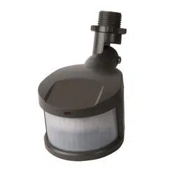
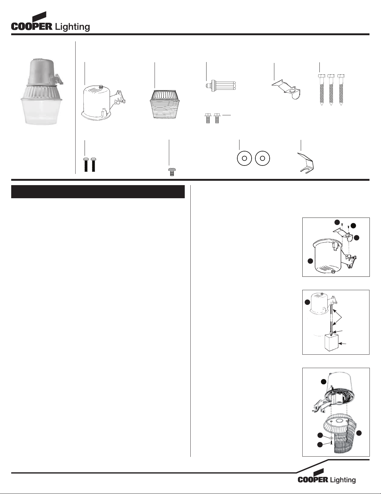
AL65FL
A. Fixture housing with
light sensor
Alojamiento del accesorio
con detector de luz
ENGLISH
E. (3) Mounting screws
(3) Tornillos de montaje
B. One-piece lens
assembly
Ensamblado del
lente de una
sola pieza
C. 65 watt fluorescent bulb
Bombilla fluorescente
de 65 vatios
D. Access cover
Cubierta de
acceso
G. (2) Lens assembly lock screws
(2) Tornillos de fijación del
ensamblado del lente
H. Green ground screw
(attached to fixture)
Tornillo de toma a
tierra verde
(conectado al accesorio)
F. (2) Access cover mounting screws (attached to fixture)
(2) Tornillos de la cubierta de acceso (conectado al accesorio)
I. (2) Washers
(2) Arandelas
J. Light shield/reflector (optional)
Escudo de luz/reflector (opcional)
Fig. 1
F
F
D
A
Fig. 2
Conduit
Junction
box
Conduit
connector
A
Fig. 3
A
B
G
I
2
1. Turn off the power at the main fuse/breaker box.
2. Loosen, but do not remove, the threaded ring at the
top of the photo sensor.
3. Slide the light shield (J) under the threaded ring.
4. Position the light shield/reflector (J) so that it blocks
light to sensor or reflects light to the sensor,
depending on the problem you are having.
5. Tighten down the threaded ring to hold the light
shield/reflector (J) in place (Fig. 4).
6. Turn the power back on.
REPLACING THE LIGHT SENSOR
1. Turn off the power at the main fuse/breaker box.
2. Remove the lens (B).
3. Remove the bulb (C) from the socket.
4. Remove the light shield/reflector (J) if applicable.
5. Remove the locknut from the outside of the
light sensor.
6. Disconnect wires from the light sensor one at a
time. Connect the new light sensor by:
• Connecting black sensor wire to the black supply
wire (hot).
• Connecting red sensor wire to the black
ballast wire.
• Connecting white sensor wire to the white
supply wire (neutral), white socket wire, and
white ballast wire.
• Attach UL approved wire connectors (sold
separately) over all connections.
7. Replace the locknut on the outside of the
light sensor.
8. Replace light shield/reflector if applicable, install
the bulb, and replace the lens.
9. Turn power back on.
TROUBLESHOOTING
This warranty does not apply to Cooper Lighting products that have been altered or repaired or
that have been subjected to neglect, abuse, misuse or accident (including shipping damages).
This warranty does not apply to products not manufactured by Cooper Lighting which have
been supplied, installed, and/or used in conjunction with Cooper Lighting products. Damage to
the product caused by replacement bulbs or corrosion or discoloration of brass components
are not covered by this warranty.
LIMITATION OF LIABILITY:
IN NO EVENT SHALL COOPER LIGHTING BE LIABLE FOR SPECIAL, INDIRECT, INCIDENTAL,
OR CONSEQUENTIAL DAMAGES (REGARDLESS OF THE FORM OF ACTION, WHETHER IN
CONTRACT, STRICT LIABILITY, OR IN TORT INCLUDING NEGLIGENCE), NOR FOR LOST PROFITS;
NOR SHALL THE LIABILITY OF COOPER LIGHTING FOR ANY CLAIMS OR DAMAGE ARISING
OUT OF OR CONNECTED WITH THESE TERMS OR THE MANUFACTURE, SALE, DELIVERY, USE,
MAINTENANCE, REPAIR OR MODIFICATION OF COOPER LIGHTING PRODUCTS, OR SUPPLY OF
ANY REPLACEMENT PARTS THEREFORE, EXCEED THE PURCHASE PRICE OF COOPER LIGHTING
PRODUCTS GIVING RISE TO A CLAIM. NO LABOR CHARGES WILL BE ACCEPTED TO REMOVE OR
INSTALL FIXTURES.
To obtain warranty service, please contact Cooper Lighting, LLC, at 1-800-334-6871, press
option 2 for Customer Service, or via e-mail [email protected] and
include the following information:
• Name, address and telephone number
• Date and place of purchase
• Catalog and quantity purchase
• Detailed description of problem
All returned products must be accompanied by a Return Goods Authorization Number issued
by the Company and must be returned freight prepaid. Any product received without a Return
Goods Authorization Number from the Company will be refused.
Cooper Lighting, LLC is not responsible for merchandise damaged in transit. Repaired or
replaced products shall be subject to the terms of this warranty and are inspected when
packed. Evident or concealed damage that is made in transit should be reported at once to
the carrier making the delivery and a claim filed with them.
Reproductions of this document without prior written approval of Cooper Lighting, LLC are strictly prohibited.
For assistance, call 1-800-334-6871 or e-mail us at [email protected]
Printed in China
ARTÍCULOS NECESARIOS
(se compran por separado)
• Destornillador en cruz (Phillips)
• Llave inglesa ajustable
• Taladro con broca de 3/16 pulgada
• Conducto portacables flexible de 1/2 pulgada (1,27 cm) de diámetro (si aplica, la longitud
depende de la aplicación)
• Conectores herméticos de conducto portacables de 1/2 pulgada (1,27 cm) (si aplica)
• Conectores de cable
ADVERTENCIAS Y PRECAUCIONES
• Lea estas instrucciones.
• Guarde estas instrucciones.
• Atienda todas las advertencias.
• Siga todas las instrucciones.
• Sólo para uso en exteriores.
• cULus para ubicaciones mojadas.
• Conecte el accesorio a una fuente de energía de 120 Voltios, 60 Hz. Cualquier otro tipo de
conexión anula la garantía.
• El accesorio debe ser instalado por personas con experiencia en cableado doméstico
o por un electricista calificado. El sistema eléctricoy el método de conexión eléctrica del
accesorio debe cumplir con el Código eléctrico nacional y los códigos locales sobre edificios.
• Utilice siempre el mismo vataje y tipo de bombilla que se incluye con el accesorio. Si no lo
hace se anulará la garantía. Vea el accesorio para el vataje requerido.
• Antes de la instalación o reparación, desconecte la alimentación eléctrica en el fusible o
interruptor de circuito.
• Desconecte la alimentación y permita que el accesorio se enfríe antes de cambiar la
bombilla o manipular el accesorio.
• Las orillas pueden cortar. Manipule con cuidado.
• Una instalación invertida podría resultar en sobrecalentamiento o acumulación de agua en
el accesorio. Este accesorio debe ser montado en posición vertical.
• UTILICE CONDUCTORES DE SUMINISTRO QUE SOPORTEN UN MÍNIMO DE 90°C.
Aviso: Las bombillas contienen mercurio y se deben desechar de acuerdo a las leyes
federales, estatales o locales. Para más información, visite: www.lamprecycle.org.
MONTAJE
DEL ACCESORIO
NOTA: Este accesorio ha sido diseñado para ser conectado a través de un conducto
portacables a una caja de conexiones (no se suministra) de metal resistente a la
intemperie adecuadamente instalada y conectada a tierra. El conducto portacables,
sus conexiones y las cajas de conexiones (cómprelos por separado) deben ser
clasificadas para ubicaciones húmedas.
Problem Cause / Solution
Light Does
Not Come On
Or Light Comes
On For Only A
Few Seconds
No power to the fixture.
• Check if circuit breaker tripped.
• Confirm wall switch is ON.
Bulb is not seated properly.
• Refer to “Installing Your Bulb” instructions.
Bulb is faulty.
• Replace bulb.
Sensor is not working properly.
• Check if light is being reflected into the sensor, causing the
fixture to turn OFF.
Wiring to the unit is loose.
• Confirm wiring is properly secured.
Caution: Turn off power before checking.
Light Does Not
Shut Off During
Daytime
Light sensor is not receiving enough light to trigger switch.
• Shine a flashlight into the light sensor for 2-3 minutes. The
fixture should switch OFF after two minutes (there is an
approximate 2 minute delay). This means the sensor is not
receiving enough light.
Photo control is faulty.
• Replace photo sensor.
Light Cycles
On and Off
Light sensor is receiving too much reflected light.
• Cover light sensor with a piece of black electrical tape. The
fixture should turn ON after a slight delay. This means that
extraneous or reflected light from the fixture is causing the
sensor to turn the unit OFF. Install light shield/reflector (J) to
block extra light from photo sensor.
Bulb is faulty.
• Replace bulb.
Fig. 4
A
J
2-YEAR LIMITED WARRANTY
THE FOLLOWING WARRANTY IS EXCLUSIVE AND IN LIEU OF ALL OTHER WARRANTIES,
WHETHER EXPRESS, IMPLIED OR STATUTORY INCLUDING, BUT NOT LIMITED TO, ANY
WARRANTY OF MERCHANTABILITY OR FITNESS FOR ANY PARTICULAR PURPOSE.
Cooper Lighting, LLC (“Cooper Lighting”) warrants to customers that, for a period of two years
from the date of purchase, Cooper Lighting’s products will be free from defects in materials
and workmanship. The obligation of Cooper Lighting under this warranty is expressly limited
to the provision of replacement products. This warranty is extended only to the original
purchaser of the product. A purchaser’s receipt or other proof of date of original purchase
acceptable to Cooper Lighting. This is required before warranty performance shall be rendered.
ESPAÑOL
3
1. Con la ayuda del patrón en la caja, marque y taladre
los agujeros para el montaje.
NOTA: Este accesorio debe ser montado en posición
vertical.
2. Instale primero los dos tornillos de montaje de la parte
inferior (E), dejando suficiente espacio entre los dos
tornillos y la superficie de montaje para acomodar
el accesorio.
3. Enrosque el tornillo de montaje (E) de la parte
superior en el agujero previamente taladrado y
sáquelo. Esto dejará el agujero roscado, lo que
facilitará la instalación del accesorio.
4. Retire la cubierta de acceso (D) de la bolsa
de piezas.
5. Instale el primer conector del conducto y el
conducto (cómprelo por separado) en la cubierta
de acceso (D).
6. Pase los cables de alimentación en el conducto
portacables y efectúe las conexiones del cableado
como está descrito en “Cableado del Accesorio”.
7. Conecte la cubierta de acceso (D) al accesorio (A)
utilizando los tornillos de la cubierta de acceso (F)
suministrados (Fig. 1).
NOTA: Asegúrese de que todos los cables estén
dentro del brazo antes de apretar los tornillos de la
cubierta de acceso (F).
8. Sujete el alojamiento a la superficie de montaje
utilizando los tres tornillos de montaje (E) que
se suministran.
9. Conecte el segundo conducto y conector del
conducto a la caja de conexiones (Fig. 2).
10. Sujete el ensamlado del lente (B) al alojamiento (A)
utilizando los 2 tornillos de fijación del ensamblado
del lente (G) y las 2 arandelas (I) suministrados
(Fig. 3).
CABLEADO DEL ACCESORIO
1. Desconecte la alimentación en la caja principal de
fusibles/interruptor de circuito.
2. Conecte el cable a tierra que se encuentra
conectado a la caja del accesorio (A) con el cable
a tierra de la caja de conexiones.
3. Conecte el cable negro del accesorio al cable negro
de suministro (activo). Acople un conector de cable
aprobado por UL (cómprelo por separado).
4. Conecte el cable blanco del accesorio al cable
blanco de suministro (neutral). Acople un conector
de cable aprobado por UL (cómprelo por separado).
NOTA: Tenga cuidado de conectar correctamente los
cables. Asegúrese de que no se extiendan tiras peladas
de cable de la tuerca para cable ni de otro conector de
cable aprobado (cómprelos por separado).
INSTALACIÓN DE LA BOMBILLA
1. Enrosque bien la bombilla (C) en el casquillo.
2. Desenrosque la bombilla (C) una o dos vueltas y
vuélvalo a enroscar para asegurarse de que esté
correctamente colocado en el casquillo.
3. Vuelva a conectar la alimentación.
INSTALACIÓN DEL ESCUDO/REFLECTOR
DE LUZ OPCIONAL
NOTA: Algunas veces los accesorios son instalados en
ubicaciones que reciben demasiada luz reflejada. El
fotodetector podría tener problemas diferenciando la
luz del día de la del accesorio. También, si el accesorio
está en una ubicación con sombra, podría pensar que
siempre es de noche. El escudo de luz/reflector puede
ser usado para bloquear o canalizar la luz hacia
el fotodetector.
1. Desconecte la alimentación en la caja principal de
fusibles/interruptor de circuito.
2. Afloje, pero no quite, el anillo roscado en la parte
superior del fotodetector.
3. Deslice el escudo/reflector (J) de luz debajo del
anillo roscado.
4. Posicione el escudo de luz/reflector (J) de modo
que bloquee o refleje la luz al detector, dependiendo
del problema que esté teniendo.
5. Apriete el anillo roscado para sujetar el escudo de
luz/reflector (J) en su lugar (Fig. 4).
6. Vuelva a encender la corriente.
REEMPLAZO DEL DETECTOR DE LUZ
1. Desconecte la alimentación en la caja principal de
fusibles/interruptor de circuito.
2. Remueva el ensamblado del lente (B).
3. Remueva la bombilla (C) del casquillo.
4. Remueva el escudo de luz/reflector (J) si aplica.
5. Remueva la contratuerca de la parte de afuera del
detector de luz.
6. Desconecte los cables del detector de luz uno
a la vez. Conecte el nuevo detector de luz de la
siguiente manera:
• Conectando el cable negro del detector al cable
negro de alimentación (activo).
• Conectando el cable rojo del detector al cable
negro de la balastra.
• Conectando el cable blanco del detector al cable
blanco de suministro (neutro), al cable blanco del
casquillo y al cable blanco de la balastra.
• Fije los cables aprobados por UL (cómprelos por
separado) sobre las conexiones.
7. Vuelva a colocar la contratuerca de seguridad en la
parte de afuera del detecor de luz.
8. Vuelva a colocar el escudo de luz/reflector (J) si
aplica. Instale la bombilla (C) y vuelva a colocar
la mica (B).
9. Vuelva a conectar la alimentación.
DIAGNOSTICO Y SOLUCION DE PROBLEMAS
Fig. 1
F
F
D
A
Fig. 2
Conducto
Caja de
conexiones
Conector del
conducto
A
Fig. 3
A
B
G
I
Problema Causa Posible/Acción Correctiva
La luz no se
enciende o
la luz se
enciende sólo
durante unos
segundos
No llega electricidad al bombilla.
• Revise si el interruptor de circuito ha saltado.
• Confirme que el interruptor de pared esté encendido.
La bombilla no está enroscado adecuadamente.
• Consulte las instrucciones de “Instalación de la lámpara”.
La bombilla está defectuoso.
• Cambie la bombilla.
El detector no está funcionando adecuadamente.
• Revise si hay luz reflejándose en el detector causando que el
accesorio se apague.
El cableado hacia la unidad está flojo.
• Confirme que el cableado esté correctamente asegurado.
Precaución: Desconecte la corriente electrica antes
de comprobarlo.
La luz no se
apaga durante
el día
El detector no está recibiendo suficiente luz como para activar
el interruptor.
• Ilumine una linterna hacia el detector de luz. El accesorio
debiera apagarse después de dos minutos (hay un retraso de
aproximadamente 2 minutos). Esto quiere decir que el detector
no está recibiendo suficiente luz.
La luz se enciende
y apaga
El detector de luz está recibiendo demasiada luz reflejada.
• Cubra el detector de luz con un pedazo de cinta aislante negra.
El accesorio debiera encenderse después de un leve retraso.
Esto quiere decir que otra luz o luz reflejada del accesorio está
causando que el detector apague la unidad. Instale el escudo
de luz/reflector (J) para bloquear la luz la luz adicional a
la fotocelda.
La bombilla está defectuoso.
• Cambie la bombilla.
GARANTIA LIMITADA DE 2 AÑOS
LA SIGUIENTE GARANTÍA ES EXCLUSIVA Y REEMPLAZA A TODAS LAS DEMÁS GARANTÍAS, YA
SEAN IMPLÍCITAS, EXPLÍCITAS O ESTATUTARIAS, INCLUIDAS ENTRE OTRAS, LAS GARANTÍAS
DE COMERCIABILIDAD E IDONEIDAD PARA UN FIN PARTICULAR.
Cooper Lighting, LLC (“Cooper Lighting”) garantiza a sus clientes que los productos de Cooper
Lighting no presentarán defectos en los materiales y en la fabricación durante un período de
dos años desde la fecha de compra. La obligación de Cooper Lighting según esta garantía se
limita expresamente al suministro de los productos de reemplazo. Esta garantía se extiende
sólo para el comprador original del producto. Un recibo del comprador u otra prueba de la
fecha de compra original aceptable para Cooper Lighting. Esto es necesario para la ejecución
de la garantía.

4
Esta garantía no se aplica a los productos de Cooper Lighting que hayan sido alterados o
reparados o que estuvieron sujetos a negligencia, abuso, mal uso o accidente (incluso los
daños durante el envío). Esta garantía no se aplica a los productos Cooper Lighting no
fabricados por Cooper Lighting que hayan sido suministrados, instalados o utilizados junto con
los productos Cooper Lighting. Los daños del producto causados por bombillas de reemplazo,
corrosión o decoloración de los componentes de latón no están cubiertos por esta garantía.
LIMITACIÓN DE RESPONSABILIDAD:
COOPER LIGHTING NO SERÁ RESPONSABLE LEGAL EN NINGÚN CASO DE DAÑOS INDIRECTOS,
ACCIDENTALES O RESULTANTES (SIN IMPORTAR LA ACCIÓN LEGAL, YA SEA POR CONTRATO,
RESPONSABILDIAD ESTRICTA O DE FORMA EXTRACONTRACTUAL INCLUYENDO LA
NEGLIGENCIA) TAMPOCO DE LA PÉRDIDA DE GANANCIAS, COOPER LIGHTING TAMPOCO
SERÁ RESPONSABLE DES O DAÑOS QUE SURJAN O ESTÉN CONECTADOS CON ESTOS
TÉRMINOS O CON LA FABRICACIÓN, VENTA, ENTREGA, USO, MANTENIMIENTOM,
REPARACIÓN O MODIFICACIÓN DE LOS PRODUCTOS DE COOPER LIGHTING O DEL
SUMINISTRO DE CUALQUIER PIEZA DE REPUESTO QUE EXCEDA EL PRECIO DE COMPRA DE
LOS PRODUCTOS DE COOPER LIGHTING ORIGINANDO UN RECLAMO. NO SE ACEPTARÁN
CARGOS POR MANO DE OBRA PARA QUITAR O INSTALAR LOS ACCESORIOS.
Para obtener el servicio de la garantía comuníquese con Cooper Lighting, LLC, al
1-800-334-6871, presione la opción 2 para el Servicio al Cliente, o por correo electrónico a
[email protected] e incluya la siguiente información:
• Nombre, dirección y número de teléfono
• Fecha y lugar de compra
• Catálogo y cantidad de la compra
• Descripción detallada del problema
Todos los productos devueltos deben estar acompañados por un Número de autorización
de productos devueltos emitido por la compañía y deben devolverse con flete prepagado.
Se rechazará todo producto recibido sin un Número de autorización de productos devueltos
desde la compañía.
Cooper Lighting, LLC no se hace responsable por la mercancía dañada durante el transporte.
Los productos reparados o reemplazados estarán sujetos a los términos de esta garantía
y se inspeccionan al ser empacados. El daño evidente y oculto que se provoque durante el
transporte se debe informar de inmediato al transportista que realiza la entrega y se debe
presentar un reclamo.
La reproducción de este documento sin la aprobación previa por escrito de Cooper Lighting, LLC está estrictamente prohibida.
Para solicitar ayuda, llame al 1-800-334-6871 o envíe un correo electrónico a ConsumerProducts@cooperlighting.com
Impreso en China
Customer First Center
1121 Highway 74 South, Peachtree City, GA 30269
www.cooperlighting.com
© 2010 Cooper Lighting, LLC
11/10
825-0571