
PoulanPRO
Instruction Manual
Manual de Instrucciones
Manuel d'lnstructions
295
,&
WARNING:
Read and follow all Safety Rules and Operating Instructions before
using this product. Failure to do so can result in serious injury.
ADVERTENCIA:
Lea el manual de instrucciones y siga todas las advertencias e en-
strucciones de seguridad. El no hacerlo puede resultar en lesiones
graves.
AVERTISSEMENT:
l_ire le manuel d'instructions et bien respecter tous les avertisse-
ments et toutes les instructions de s_curit_. Tout d_faut de le faire
pourrait entrafner des blessures graves.
Electrolux Home Products, Inc.
250 Bobby Jones Expressway
Augusta, GA 30907
Electrolux Canada Corporation
6150 McLaughlin Road
Mississauga, Ontario L5R 4C2
[] Ftorn the EtectroluxGroup. The world's No.l choice,
I_ITCH_N,CLE,_N/NGAN_OUTDOOR,_p,'_NCESCOt4_NEIJ
Copyright _2003 Etectrolux Home Products, Inc. 530163893 2/21/03
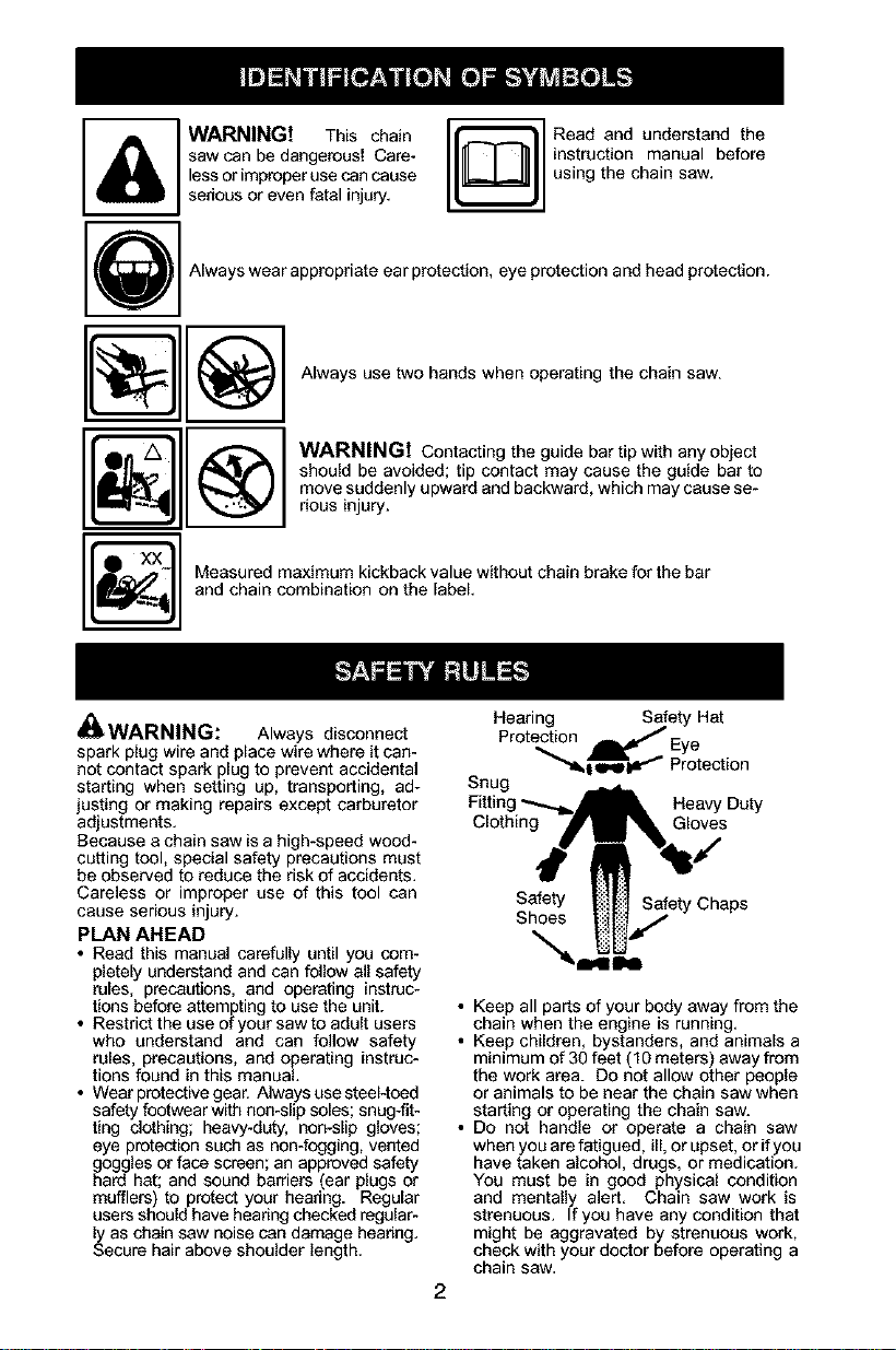
WARNINGt This chain
saw can be dangerous! Care-
lessor improperuse can cause
sedous or even fatal injury.
Read and understand the
instruction manual before
using the chain saw.
Always wear appropdate ear protection, eye protection and head protection.
Always use two hands when operating the chain saw.
WARNINGt Contacting the guide bar tip with any object
should be avoided; tip contact may cause the guide bar to
move suddenly upward and backward, which may cause se-
rious injury.
Measured maximum kickback value without chain brake for the bar
and chain combination on the label.
_ WARNING: Always disconnect
spark plug wire and place wire where it can-
not contact spark plug to prevent accidental
starting when setting up, transporting, ad-
justing or making repairs except carburetor
adjustments.
Because a chain saw is a high-speed wood-
catting tool, special safety precautions must
be observed to reduce the risk of accidents.
Careless or improper use of this tool can
cause serious injury.
PLAN AHEAD
• Read this manual carefully until you com-
pletely understand and can follow all safety
rules, precautions, and operating instruc-
tions before attempting to use the unit.
• Restrict the use of your saw to adult users
who understand and can follow safety
rules, precautions, and operating instruc-
tions found in this manual.
• Wear protective gear. Always use steel-toed
safety footwear with non-slip soles; snug-fit-
ting clothing; heavy-dL_y, non-slip gloves;
eye protection such as non-fogging, vented
goggles or face screen; an approved safety
hard hat; and sound barriers (ear plugs or
mufflers) to protect your headng. Regular
users should have headng checked regular-
ly as chain saw noise can damage headog.
Secure hair above shoulder length.
Hearing Safety Hat
Protection _Eye
"_l O'IP_ Protection
Snug
Heavy Duty
Clothing Gloves
Safety Safety Chaps
Shoes
• Keep all parts of your body away from the
chain when the engine is running.
• Keep children, bystanders, and animals a
minimum of 30 feet (1g meters) away from
the work area. Do not allow other people
or animals to be near the chain saw when
starting or operating the chain saw.
• Do not handle or operate a chain saw
when you are fatigued, ill, or upset, or ifyou
have taken alcohol, drugs, or medication.
You must be in good physical condition
and mentally alert. Chain saw work is
strenuous. If you have any condition that
might be aggravated by strenuous work,
check with your doctor before operating a
chain saw.
• Carefullyplanyoursawingoperationinad-
vance.Donotstartcuttinguntilyouhavea
clearworkarea,securefooting,and,ifyou
arefellingtrees,aplannedretreatpath.
OPERATE YOUR SAW SAFELY
• Do not operate a chain saw with one hand.
Serious injury to the operator, helpers, by-
standers or any combination of these per-
sons may result from one-handed opera-
tion. A chain saw is intended for
two-handed use.
• Operate the chain saw only in a well-venti-
lated outdoor area.
• Do not operate saw from a ladder or in a
tree.
• Make sure the chain will not make contact
with any object while starting the engine.
Never try to start the saw when the guide
bar is in a cut.
• Do not put pressure on the saw at the end
of the cut. Applying pressure can cause
you to lose control when the cut is com-
pleted.
• Stop the engine before setting the saw
down.
• Do not operate a chain saw that is dam-
aged, improperly adjusted, or not com-
pletely and securely assembled. Always
replace bar, chain, hand guard, or chain
brake immediately if it becomes damaged,
broken or is otherwise removed.
• With the engine stopped, hand carry the
chain saw with the muffler away from your
body, and the guide bar and chain to the
rear, preferably covered with a scabbard.
MAINTAIN YOUR SAW IN GOOD
WORKING ORDER
• Have all chain saw service performed by a
qualified service dealer with the exception
of the items listed in the maintenance sec-
tion of this manual. Forexample, if improp-
er tools are used to remove or hold the fly-
wheel when servicing the clutch, structural
damage to the flywheel can occur and
cause the flywheel to burst.
• Make certain the saw chain stops moving
when the throttle trigger is released. For
correction, refer to CARBURETOR AD-
JUSTMENTS.
• Never modify your saw in any way.
• Keep the handles dry, clean, and free ofoil
or fuel mixture.
• Keep fuel and oil caps, screws, and fas-
teners securely tightened.
• Use only Poulan PRO@ accessories and
replacement parts as recommended.
HANDLE FUEL WITH CAUTION
• Do not smoke while handling fuel or while
operating the saw.
• Eliminate all sources of sparks or flame in
the areas where fuel is mixed or poured.
There should be no smoking, open flames,
or workthat could cause sparks. Allow en-
gine to cool before refueling.
• Mix and pour fuel in an outdoor area on
bare ground; store fuel in a cool, dry, well
ventilated place; and use an approved,
marked container for all fuel purposes.
Wipe up aUfuel spills before starting saw.
• Move at least 10 feet (3 meters) from fuel-
ing site before starting engine.
• Turn the engine off and let saw cool in a
non-combustible area, not on dry leaves,
straw, paper, etc. Slowly remove fuel cap
and refuel unit.
• Store the unit and fuel in an area where fuel
vapors cannot reach sparks or open
flames from water heaters, electric motors
or switches, furnaces, etc.
KICKBACK
_kWARNING: Avoid kickback which
can result in serious injury. Kickback is the
backward, upward or sudden forward motion
of the guide bar occurring when the saw
chain near the upper tip of the guide bar con-
tacts any object such as a log or branch, or
when the wood closes in and pinches the
saw chain inthe cut. Contacting a foreign ob-
ject in the wood can also result in loss of
chain saw control.
• Rotational Kickback can occur when the
moving chain contacts an object at the up-
per tip of the guide bar. This contact can
cause the chain to dig into the object,
which stops the chain for an instant. The
result is a lightning fast, reverse reaction
which kicks the guide bar up and back to-
ward the operator.
• Pinch-Kickback can occur when the the
wood closes in and pinches the moving
saw chain in the cut along the top of the
guide bar and the saw chain is suddenly
stopped. This sudden stopping of the
chain results in a reversal of the chain
force used to cut wood and causes the
saw to move in the opposite direction of the
chain rotation. The saw is driven straight
back toward the operator.
• Pull-In can occur when the moving chain
contacts a foreign object in the wood in the
cut along the bottom of the guide bar and the
saw chain is suddenly stopped. This sudden
stopping pulls the saw forward and away
from the operator and could easily cause the
operator to lose control of the saw.
Avoid Pinch-Kickback:
• Be extremely aware of situations or ob-
structions that can cause material to pinch
the top of or otherwise stop the chain.
• Do not cut more than one log at a time.
• Do not twist the saw as the bar is with-
drawn from an undercut when bucking.
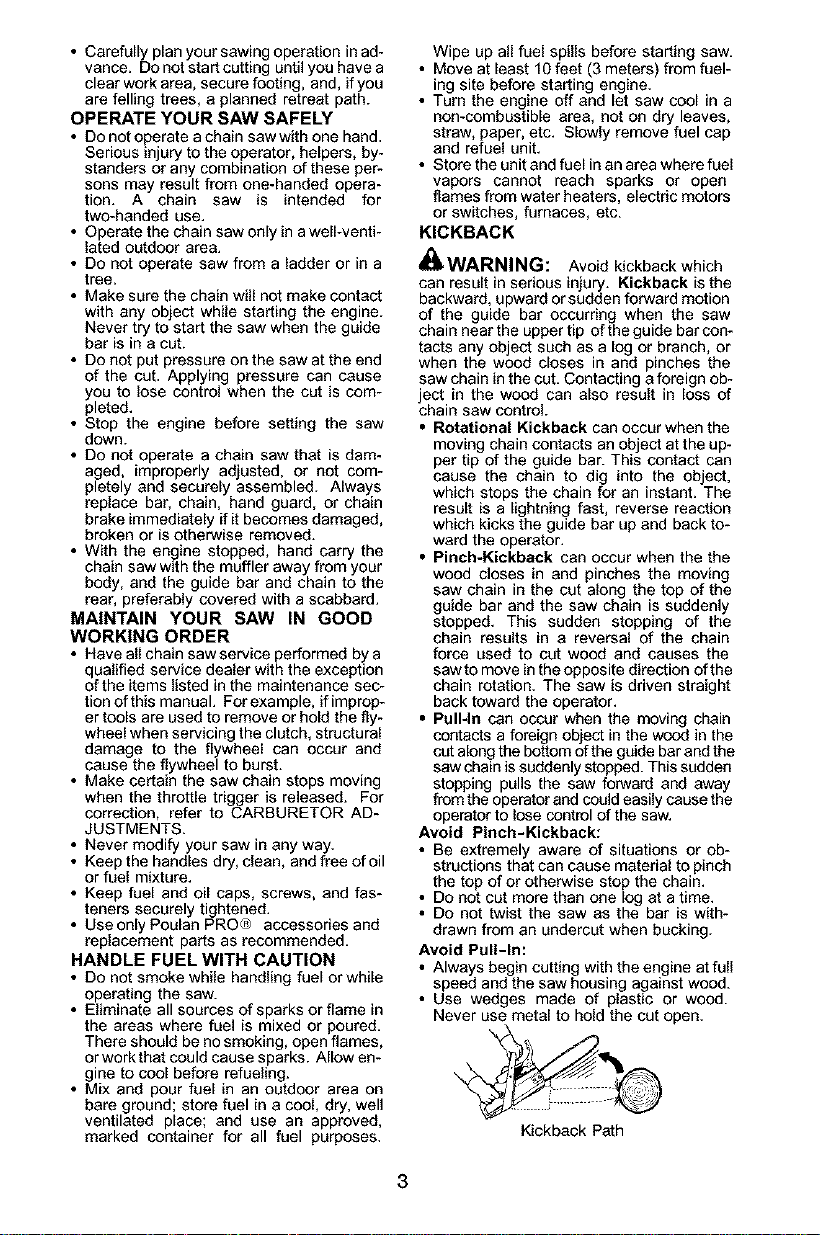
Avoid Pull-In:
• Always begin cutting with the engine at full
speed and the saw housing against wood.
• Use wedges made of plastic or wood.
Never use metal to hold the cut open.
Kickback Path
Clear The Working Area
REDUCE THE CHANCE OF
KICKBACK
• Recognize that kickback can happen.
With a basic understanding of kickback,
you can reduce the element of surprise
which contributes to accidents.
• Never let the moving chain contact any ob-
ject at the tip of the guide bar.
• Keep the working area free from obstruc-
tions such as other trees, branches, rocks,
fences, stumps, etc. Eliminate or avoid
any obstruction that your saw chain could
hit while you are cutting. When cutting a
branch, do not let the guide bar contact
branch or other objects around it.
• Keep your saw chain sharp and properly
tensioned. A loose or dull chain can in-
crease the chance of kickback occurring.
Follow manufacturer's chain sharpening
and maintenance instructions. Check ten-
sion at regular intervals with the engine
stopped, never with the engine running.
Make sure the chain brake nuts are se-
curely tightened after tensioning the chain.
• Begin and continue cutting at full speed. If
the chain is moving at a slower speed,
there is greater chance of kickback occur-
ring.
• Cut one log at a time.
• Use extreme caution when re-entering a
previous cut.
• DO not attempt cuts starting with the tip of
the bar (plunge cuts).
• Watch for shifting logs or other forces that
could close a cut and pinch or fall into
chain.
• Use the Reduced-Kickback Guide Bar
and Low-Kickback Chain specified for
your saw.
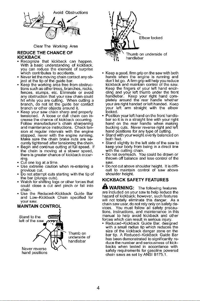
MAINTAIN CONTROL
Stand to the
left of the_
Never reverse _
hand positions
[
II Thumb on
| underside of
k handlebar
Elbow locked
Thumb on underside of
handlebar
• Keep a good, firm grip on the saw with both
hands when the engine is running and
don't let go. A firm grip will help you reduce
kickback and maintain control of the saw.
Keep the fingers of your left hand encir-
cling and your left thumb under the front
handlebar. Keep your right hand com-
pletely around the rear handle whether
your are right handed or left handed. Keep
your left arm straight with the elbow
looked.
• Position your left hand on the front handle-
bar so it is in a straight line with your right
hand on the rear handle when making
bucking cuts. Never reverse right and left
hand positions for any type of cutting.
• Stand with yoor weight evenly balanced on
both feet.
• Stand slightly to the left side of the saw to
keep your body from being in a direct line
with the cutting chain.
• Do not overreach. You could be drawn or
thrown off balance and lose control of the
saw.
• Do not cut above shoulder height. Itis diffi-
cult to maintain control of saw above
shoulder height.
KICKBACK SAFETY FEATURES
_WARNING: The following features
are included on your saw to help reduce the
hazard of kickback; however, such features
will not totally eliminate this danger. As a
chain saw user, do not rely only on safety de-
vices. You must follow all safety precau-
tions, instructions, and maintenance in this
manual to help avoid kickback and other
forces which can result in serious injury.
• Reduced-Kickback Guide Bar, designed
with a small radius tip which reduces the
size of the kickback danger zone on the
bar tip. A Reduced-Kickback Guide Bar
has been demonstrated to significantly re-
duce the number and seriousness of kick-
backs when tested in accordance with
safety requirements for gasoline powered
chain saws as set by ANSI B175.1.
Reduced Kickback Symmetrical Guide Bar
_'--__'_I Ra_io_Tip
Large Radius Tip
• Low-Kickback Chain, designed with a
contoured depth gauge and guard link
which deflect kickback force and allow
wood to gradually ride into the cutter. Low-
Kickback Chain has met kickback per-
formance requirements when tested on a
representative sample of chain saws be-
low 3.8 cubic inch displacement specified
in ANSI B175.1.
Contoured Depth GaL_ge
_£k Elongated Guard LinkDeflects
ickback force
Low- KJckback
and allows
wood
Chain to gradually ride
into cutter
_""_"_,_Can Obstruct MateriaJ
Not a Low- KJckback Chain
• Front Hand Guard, designed to reduce the
chance of your left hand contacting the
chain if your hand slips off the front handle-
bar.
• Position of front and rear handlebars, de-
signed with distance between handles and
"in-line" with each other. The spread and
"in-line" position of the hands provided by
this design work together to give balance
and resistance in controlling the pivot of
the saw back toward the operator if kick-
back occurs.
CHAIN BRAKE AND CKA ANGLE
• Chain Brake, designed to stop the chain in
the event of kickback.
_WARNING: WE DO NOT REP-
RESENT AND YOU SHOULD NOT AS-
SUME THAT THE CHAIN BRAKE WILL
PROTECT YOU iN THE EVENT OF A
KICKBACK. Kickback is a lightning fast ac-
tion which throws the bar and rotating chain
back and up toward the operator. Kickback
can be caused by allowing contact of the bar
tip in the danger zone with any hard object.
Kickback can also be caused by pinching the
saw chain along the top of the guide bar. This
action may push the guide bar rapidly back
toward the operator. Either of these events
may cause you to lose control of the saw
which could result in serious injury or even
death. DO NOT RELY UPON ANY OF THE
DEVICES BUILT INTO YOUR SAW. YOU
SHOULD USE THE SAW PROPERLY AND
CAREFULLY TO AVOID KICKBACK. Re-
duced-kickback guide bars and low-kick-
back saw chains reduce the chance and
magnitude of kickback and are recom-
mended. Your saw has a low kickback chain
and bar as original equipment. Repairs on a
chain brake should be made by an autho-
rized servicing dealer. Take your unit to the
place of purchase if purchased from a ser-
vicing dealer, or to the nearest authorized
master service dealer.
• Tip contact in some cases may cause a
lightning fast reverse REACTION, kicking
the guide bar up and back toward the oper-
ator.
• Pinching the saw chain along the top of the
guide bar may push the guide bar rapidly
back toward the operator.
• Either ofthese reactions maycauseyouto
lose control of the saw which could result
in serious injury.Do not rely exclusively
upon the safety devices built into your saw.
_WARNING: Computed kickback
angle (CKA) listed on your saw and listed in
the CKA table below represents angle of
kickback your bar and chain combinations
will have when tested in accordance with
CSA (Canadian Standards Association) and
ANSI standards. When purchasing replace-
ment bar and chain, considerations should
be given to the lower CKA values. Lower
CKA values represent safer angles to the
user, higher values indicate more angle and
higher kick energies. Computed angles rep-
resented in the non-activated column indi-
cate total energy and angle associated with-
out activation of the chain brake during
kickback. Activated angle represents chain
stopping time relative to activation angle of
chain brake and resulting kick angle of saw.
in all cases lower CKA values represent a
safer operating environment for the user.
The following guide bar and chain combina-
tions meet kickback requirements of CSA
Z62.1, Z62.3, & ANSI B175.1 when used on
saws listed in this manual. Use of bar and
chain combinations other than those listed is
not recommended and may not meet the
CKA requirements per standard.
Computed kickback angle (CKA) Table
MODEL P/N BA_D = CHAIN P/N
I I
295 952044815 I 20" J 952051310
CKA without chain brake
31°
NOTE: If this saw is to be used for commer-
cial logging, a chain brake is required and
shall not be removed or otherwise disabled
to comply with Federal OSHA Regulations
for Commercial Logging.
SAFETY NOTICE: Exposure to vibrations
through prolonged use of gasoline powered
hand tools could cause blood vessel or nerve
damage in the fingers, hands, and joints of
people prone to circulation disorders or
abnormal swellings. Prolonged use in cold
weather has been linked to blood vessel
damage in otherwise healthy people. If
symptoms occur such as numbness, pain,
loss of strength, change in skin color or texture,
or toss of feeling in the fingers, hands, or joints,
discontinue the use of this tool and seek
medical attention. An antiwibration system
does not guarantee the avoidance of these
problems. Users who operate power tools on
a continual and regular basis must monitor
closely their physical condition and the
condition of this tool.
SPECIAL NOTICE: Your saw is equipped
with a temperature limiting muffler and spark
arresting screen which meets the
requirements of California Codes 4442 and
4443. All U.S. forest land and the states of
California, Idaho, Maine, Minnesota, New
Jersey, Oregon, and Washington require by
law that many internal combustion engines
to be equipped with a spark arresting screen.
If you operate a chain saw in a state or locale
where such regulations exist, you are legally
responsible for maintaining the operating
condition of these parts. Failure to do so is
a violation of the law. Refer to the SERVICE
section for maintenance of the spark
arresting screen.
Failure to follow all Safety Rules and Precau-
tions can result in serious injury. If situations
occur which are not covered in this manual,
use care and good judgement. If you need
assistance, contact your authorized service
dealer or call 1-800-554-6723.
STANDARDS: This saw is listed by Under-
writer's Laboratories, Inc., in accordance with:
ANSI BI75.f-2860 American National
Standards for Gasoline-Powered Chain
Saws - Safety Requirements
CSA Z62.1-1995 Chain Saws - Occupa-
tional Health and Safety
CSA Z62.3-1996 Chain Saw Kickback Oc-
cupational Health and Safety
Protective gloves (not provided) should be
worn during assembly.
ATTACHING THE BAR & CHAIN (If not
already attached)
_ WARNING: If receivod assembled,
repeat all steps to ensure yoursaw is prop-
erly assembled andall fasteners aresecure.
Always wear gloves when handling the
4,
chain. The chain is sharp and can cut you
even when it is not moving!
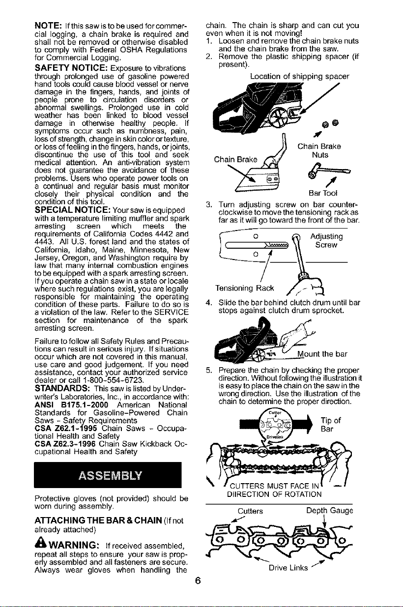
1. Loosen and remove the chain brake nuts
and the chain brake from the saw.
2. Remove the plastic shipping spacer (if
present).
Location of shipping spacer
ChanBak
Ch Nuts
Bar Tool
Turn adjusting screw on bar counter-
clockwise to move the tensioning rack as
far as it will go toward the front of the bar,
_ o _ Adjusting
] ( _ _ Screw
Tensioning Rack _,//_ '_
Slide the bar behind clutch drum until bar
stops against clutch drum sprocket.
_t the bar
5. Prepare the chain by checking the proper
direction. Without following the illustration it
is easy to place the chain on the saw in the
wrong direction. Usethe iUustration ofthe
chain to determine the proper direction.
rof
DIIRECTION OF ROTATION
Cutters Depth Gauge
Drive Links "/_
6. Placethechainoverandbehindthe
clutch,fittingthedrivelinksintheclutch
drumsprocket.
Placechainontothesprocket
7. Fitbottomofdrivelinksbetweenthe
teethinthesprocketinthenoseofthe
guidebar.
8. Fitchaindrivelinksintobargroove.
9. Pullthebarforwarduntilthechainis
snuginthegrooveofthebar.Ensureall
drivelinksareinthebargroove.
10.Holdguidebaragainstthesawframe
andinstallthechainbrake.
11.Replacethechainbrakenutsandtighten
fingertight.Oncethe chainisten-
sioned,youwillneedtotightenchainbra-
kenuts.
CHAINTENSION (Including units with
chain already installed)
NOTE: When adjusting chain tension,
make sure the chain brake nuts are finger
tight only. Attempting to tension the chain
when the chain brake nuts are tight can
cause damage.
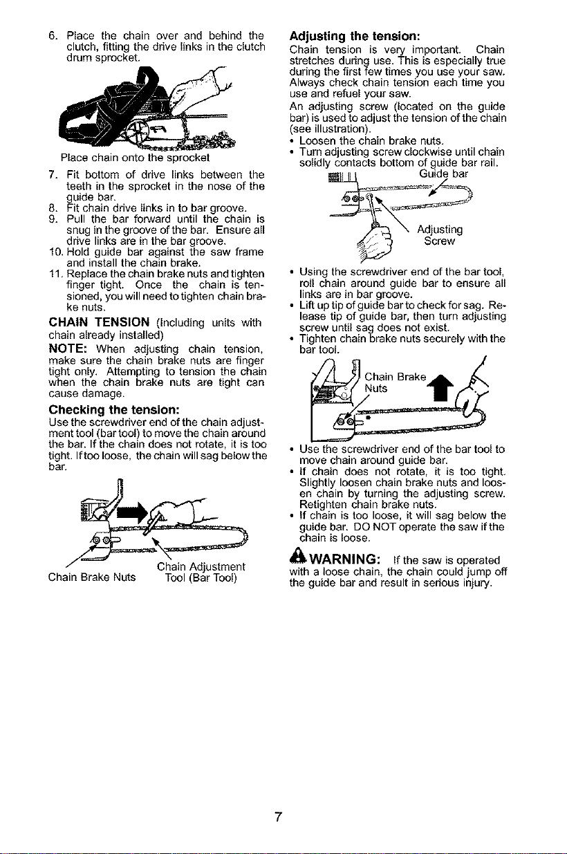
Checking the tension:
Use the screwdriver end of the chain adjust-
ment tool (bar tool) to move the chain around
the bar. If the chain does not rotate, it is too
tight. Iftoo loose, the chain will sag below the
bar.
Chain Brake Nuts Tool (Bar Tool)
Adjusting the tension:
Chain tension is very important. Chain
stretches during use. This is especially true
during the first few times you use your saw.
Always check chain tension each time you
use and refuel your saw.
An adjusting screw (located on the guide
bar) is used to adjust the tension of the chain
(see illustration).
• Loosen the chain brake nuts.
• Turn adjusting screwclockwise until chain
solidly contacts bottom of guide bar rail.
Guide bar
• Using the screwdriver end of the bar tool,
roll chain around guide bar to ensure all
links are in bar groove.
• Lift uptip of guide bar tocheck for sag. Re-
lease tip of guide bar, then turn adjusting
screw until sag does not exist.
• Tighten chain brake nuts securely with the
bar tool.
Chain Brake
• Use the screwdriver end of the bar tool to
move chain around guide bar.
• If chain does not rotate, it is too tight.
Slightly loosen chain brake nuts and loos-
en chain by turning the adjusting screw.
Retighten chain brake nuts.
• If chain is too loose, it will sag below the
guide bar. DO NOT operate the saw if the
chain is loose.
_1_WARNING: If the saw is operated
with a loose chain, the chain could jump off
the guide bar and result in serious injury.
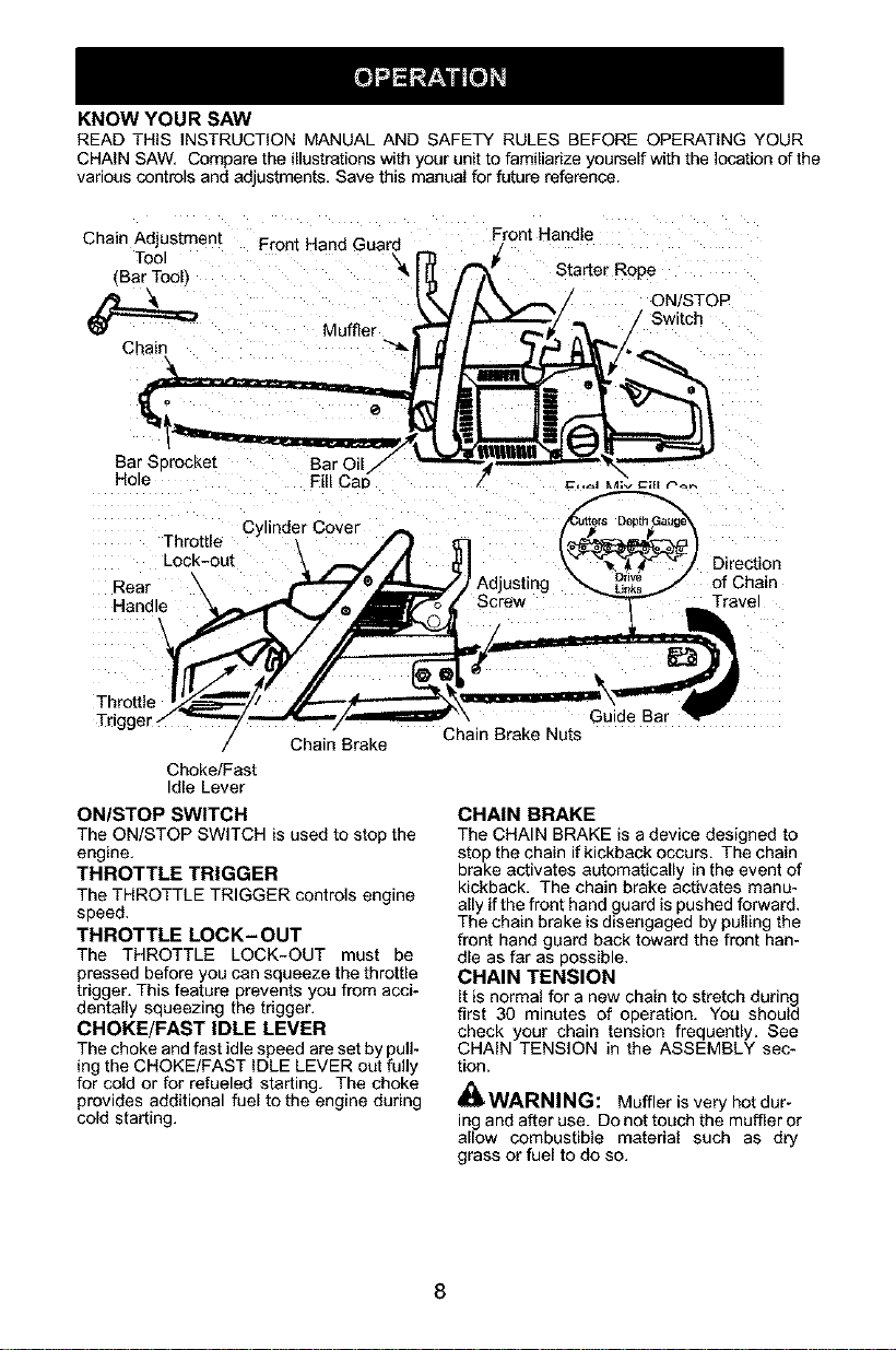
KNOW YOUR SAW
READ THIS INSTRUCTION MANUAL AND SAFETY RULES BEFORE OPERATING YOUR
CHAIN SAW, Compare the illustrations with your unit to familiarize yourself with the location of the
various controls and adjustments. Save this manual for future reference.
Front Handle
Chain Adjus[men[ Front Hand Guard
Tool _ Starter Rope
fBar Tool_
ON/STOP
Muffler Switch
Chain
Cy inder Cover
Throttle
LOCK-OUt
Rear \ Adjusting of Chain
Handle Screw Travel
Throttle
Trigger
/ Chain Brake
Choke/Fast
Idle Lever
ONISTOP SWITCH
The ON/STOP SWITCH is used to stop the
engine.
THROTTLE TRIGGER
The THROTTLE TRIGGER controls engine
speed.
THROTTLE LOCK- OUT
The THROTTLE LOCK-OUT must be
pressed before you can squeeze the throttle
trigger. This feature prevents you from acci-
dentally squeezing the trigger,
CHOKE/FAST IDLE LEVER
The choke and fast idle speed are set by pull-
ing the CHOKE/FAST IDLE LEVER out fully
for cold or for refueled starting, The choke
provides additional fuel to the engine during
cold starting.
Guide Bar
Chain Brake Nuts
CHAIN BRAKE
The CHAIN BRAKE is a device designed to
stop the chain if kickback occurs. The chain
brake activates automatically in the event of
kickback. The chain brake activates manu-
ally if the front hand guard is pushed forward,
The chain brake is disengaged by pulling the
front hand guard back toward the front han-
dle as far as possible.
CHAIN TENSION
It is normal for a new chain to stretch during
first 30 minutes of operation. You should
check your chain tension frequently. See
CHAIN TENSION in the ASSEMBLY sec-
tion.
WARNING: Muffler is very hot dur-
ing and after use. Do not touch the muffler or
allow combustible material such as dry
grass or fuel to do so.
WARNING: Remove fuel cap slow-
ly when refueling.
FUELING ENGINE
This engine is certified to operate on
unleaded gasoline, Before operation,
gasoline must be mixed with a good quality
synthetic 2-cycle air-cooled engine oil
designed to be mixed at a ratio of 40:1.
PoulanANeed Eater brand synthetic oil is
recommended. Mix gasoline and oil at aratio
of 40:1. A40:1 ratio is obtained by mixing 3.2
ounces of oil with 1 gallon of unleaded
gasoline. Included with this saw is a 3.2
ounce container of oil. Pour the entire
contents of this container into 1 gallon of
gasoline to achieve the proper fuel mixture.
DO NOT USE automotive oil or boat oil. These
oils will cause engine damage. When mixing
fuel, follow instructions printed on container.
Once oil is added to gasoline, shake container
momentarily to assure that the fuel is
thoroughly mixed. Always read and follow the
safety rules relating to fuel before fueling your
unit.
BAR AND CHAIN LUBRICATION
The bar and chain require continuous lubri-
cation. Lubrication is provided by the auto-
matic oiler system when the oil tank is kept
filled. Lack ofoil will quickly ruin the bar and
chain. Too little oil will cause overheating
shown by smoke coming from the chain and/
or discoloration of the bar.
In freezing weather oil will thicken, making it
necessary to thin bar and chain oil with a
small amount (5 to 10%) of #1 Diesel Fuel or
kerosene. Bar and chain oil must be free
flowing for the oil system to pump enough oil
for adequate lubrication.
Genuine Poulan or Poulan PRO® bar and
chain oil is recommended to protect your unit
against excessive wear from heat and
friction. Poulan orPoulan PRO® oil resists
high temperature thinning. If Poulan or
Poulan PRO® bar and chain oil is not
available, use a good grade SAE 30 oil.
• Never use waste oil for bar and chain lubri-
cation.
• Always stop the engine before removing
the oil cap.
IMPORTANT
Experience indicates that alcohol-blended
fuels (called gasohol or using ethanol or
methanol) can attract moisture which leads
to separation and formation of acids during
storage. Acidic gas can damage the fuel
system of an engine while in storage. To
avoid engine problems, the fuel system
should be emptied before storage for 30
days or longer. Drain the gas tank, start the
engine and let it run until the fuel lines and
carburetor are empty. Use fresh fuel next
season. See STORAGE section for addi-
tional information.
_WARNING:
The chain must not
move when the engine runs at idle speed. If
the chain moves at idle speed refer to CAR-
BURETOR ADJUSTMENT within this
manual. Avoid contact with the muffler. Ahot
muffler can cause serious burns.
To stop the engine move the ON/STOP
switch to the STOP position.
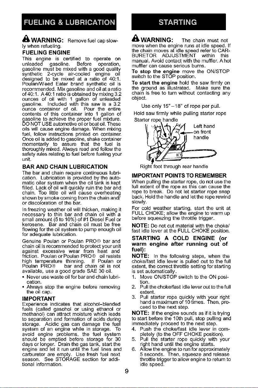
To start the engine hold the saw firmly on
the ground as illustrated. Make sure the
chain is free to turn without contacting any
object.
Use only 15"-18" of rope per pull.
Hold saw firmly while pulling starter rope
Starter rope handle
_( _\'_ _1" Left hand
front
Right foot through rear handle
IMPORTANT POINTS TO REMEMBER
When pullin£_the starter rope, do not use the
full extent otthe rope as this can cause the
rope to break. Do not let starter rope snap
back. Hold the handle and let the rope rewind
slowly.
For cold weather starting, start the unit at
FULL CHOKE; allow the engine to warm up
before squeezing the throttle trigger.
NOTE: Do not cut material with the choke/
fast idle lever at the FULL CHOKE position.
STARTING A COLD ENGINE (or
warm engine after running out of
fuel):
NOTE: In the following steps, when the
choke/fast idle lever is pulled out to the full
extent, the correct throttle setting for starting
is set automatically.
1. Move ON/STOP switch to the ON posi-
tion.
2. Pull the choke/fast idle lever out to the full
extent.
3. Pull starter rope quickly with your right
hand a maximum of 10 times. Then, pro-
ceed to the next step.
NOTE: If the engine sounds as if it is trying
to start before the 10th pull, stop pulling and
immediately proceed to the next step.
4. Push the choke/fast idle lever in com-
pletely (to the OFF CHOKE position).
5. Pull the starter rope quickly with your
right hand until the engine starts.
6. Allow the engine to run for approximately
5 seconds. Then, squeeze and release
throttle trigger to allow engine to return to
idle speed.
CHOKE/FAST IDLE LEVER
STARTING A WARM ENGINE
1. MeveON/STOPswitchtotheONposifino.
2. Pull the choke/fast idle lever out tothe full
extent; then, push the lever back in com-
pletely (to the OFF CHOKE position). This
will set the fast idle locktothe start position.
3. Pull the starter rope quickly with your right
hand untilthe engine starts.
4. Squeeze and release the throttle trigger
to allow engine to return to idle speed.
DIFFICULT STARTING (or starting a
flooded engine)
The engine may be flooded if it has not started
after 10 pulls.
Flooded engines can be cleared of excess fuel
by following the warm engine starting proce-
dure listed above. Ensure the ON/STOP
switch is in the ON position.
Starting could require many pulls depending on
how badly unit is flooded. If engine still fails to
start, refer to TROUBLESHOOTING TABLE
or cell 1-800-554-6723.
CHAIN BRAKE
_ WARNING: Ifthe brake baed isworn
too thin it may break when the chain brake is
triggered. With a broken brake band, the chain
brake will not stop the chain. The chain brake
should be replaced by an authorized service
dealer if any part is worn to less than 0.020"
(0.5 mm) thick. Repairs on a chain brake
should be made by an aL_horized service deal-
er. Take your unit to the place of purchase if
purchased from a servicing dealer, or to the
nearest authorized master service dealer.
• This saw is equipped with a chain brake.
The brake is designed to stop the chain if
kickback occurs.
• The inertia-activated chain brake is
activated if the front hand guard is pushed
forward, either manually (by hand) or
automatically (by sudden movement).
• If the brake is already activated, it is
disengaged by pulling the front hand guard
back toward the front handle as far as
possible.
• When cutting with the saw, the chain brake
must be disengaged.
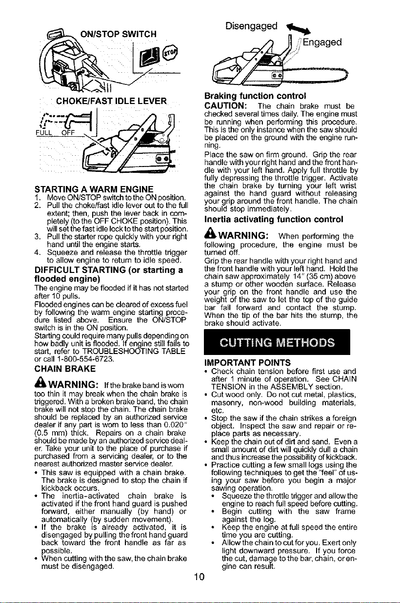
Disengaged
_ Engaged
Braking function control
CAUTION: The chain brake must be
checked several times daily. The engine must
be running when performing this procedure.
This is the only instance when the saw should
be placed on the ground with the engine run-
ning.
Place the saw on firm ground. Grip the rear
handle with your right hand and the front han-
dle with your left hand. Apply full throttle by
fully depressing the throttle trigger. Activate
the chain brake by turning your left wrist
against the hand guard without releasing
your grip around the front handle. The chain
should stop immediately.
Inertia activating function control
_WARNING: When performing the
following procedure, the engine must be
turned off.
Grip the rear handle with your right hand and
the front handle with your left hand. Hold the
chain saw approximately 14" (35 cm) above
a stump or other wooden surface. Release
your grip on the front handle and use the
weight of the saw to let the top of the guide
bar fall forward and contact the stump.
When the tip of the bar hits the stump, the
brake should activate.
lO
IMPORTANT POINTS
• Check chain tension before first use and
after 1 minute of operation. See CHAIN
TENSION in the ASSEMBLY section.
• Cut wood only. Do not cut metal, plastics,
masonry, non-weed building materials,
etc.
• Stop the saw if the chain strikes a foreign
object. Inspect the saw and repair or re-
place parts as necessary.
• Keep the chain OL_of dirt and sand. Even a
small amount of dirt will quickly dull a chain
and thus increase the possibility of kickback.
• Practice cutting a few small logs using the
following techniques to get the "feel" of us-
ing your saw before you begin a major
sawing operation.
• Squeeze the throtUe tdgger ned allow the
engine to reach full speed before CL_ting.
• Begin cutting with the saw frame
against the log.
• Keep the engine at full speed the entire
time you are cutting.
• Allow the chain to cut for yoc. Exert only
light downward pressure. If you force
the cut, damage to the bar, chain, or en-
gine can result.
• Releasethethrottletriggerassoonas
thecutiscompleted,allowingtheen-
ginetoidle.Ifyourunthesawatfull
throttlewithoutacuttingload,unneces-
sarywearcanoccurtothechain,bar,
andengine.
• Toavoidlosingcontrolwhencutiscom-
plete,donotputpressureonsawatend
ofcut.
• Stoptheenginebeforesettingthesaw
downaftercutting.
TREE FELLING TECHNIQUES
_WARNING: Check for broken or
dead branches which can fall while cutting
causing serious injury. Do not cut near build-
ings or electrical wires if you do not know the
direction of tree fall, nor cut at night since you
will not be ale to see well, nor during bad
weather such as rain, snow, or strong winds,
etc. If the tree makes contact with any utility
line, the utility company should be notified
immediately.
• Carefully planyoursawingoperation inad-
vance.
• Clear the work area. You need aclear area
all around the tree so you can have secure
footing.
• Study the natural conditions that can
cause the tree to fall in a particular direc-
tion.
Natural conditions that can cause a tree to
fall in a particular direction include:
• The wind direction and speed.
• The lean of the tree. The lean of a tree
might not be apparent due to uneven or
sloping terrain. Use a plumb or level to de-
termine the direction of tree lean.
• Weight and branches on one side.
• Surrounding trees and obstacles.
Look for decay and rot Ifthetrunk is rotted,
it can snap and fall toward the operator.
Check for broken or dead branches which
can fall on you while cutting.
Make sure there is enough room for the tree
to fall. Maintain a distance of 2-1/2 tree
lengths from the nearest person or other ob-
jects. Engine noise can drown out a warning
call.
Remove dirt, stones, loose bark, nails, sta-
ples, and wire from the tree where cuts are to
be made.
Plan a clear retreat path to the rear and diag-
onal to the line of fall.
_, ,_. Plan a clear retreat path
-,%
;t.... £)--"""_- Direction of Fall
/÷#"
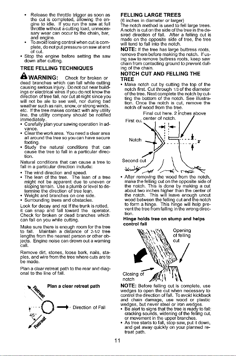
FELLING LARGE TREES
(6 inches in diameter or larger)
The notch method is used to fell large trees.
A notch is cut on the side of the tree in the de-
sired direction of fall. After a felling cut is
made on the opposite side of tree, the tree
will tend to fall into the notch.
NOTE: If the tree has large buttress roots,
remove them before making the notch. If us-
ing saw to remove buttress roots, keep saw
chain from contacting ground to prevent dull-
ing of the chain.
NOTCH CUT AND FELLING THE
TREE
• Make notch cut by cutting the top of the
notch first. Cut through 1/3of the diameter
of the tree. Next complete the notch by cut-
ting the bottom of the notch. See illustra-
tion. Once the notch is cut, remove the
notch of wood from the tree.
Final cut here. 2 _nches above
F ret cut center, "P!, _,'q-iof notch.,J I /
Notch : .... _/--
..... __2"
Second cut
• After removir the wood from the notch,
make the fellin cut on the opposite side of
the notch. This is done by making a cut
about two inches higher than the center of
the notch. This will leave enough uncut
wood between the felling cut and the notch
to form a hinge. This hinge will help pre-
vent the tree from falling inthe wrong direc-
tion.
Hinge holds tree on stump and helps
control fall
Opening
of felling
cut
Closing of
notch
NOTE: Before felling cut is complete, use
wedges to open the cut when necessary to
control the direction of fall. To avoid kickback
and chain damage, use wood or plastic
wedges, but never steel or iron wedges.
• Be aled to signs that the tree is ready to fall:
cracking sounds, widening of the felling cut,
or movement in the upper branches.
• As tree starts to fall, stop saw, put itdown,
and get away quickly on your planned re-
treat path.
11
• DO NOT cut down a partially fallen tree
with your saw. Be extremely cautious with
partially fallen trees that may be poorly
supported. When e tree doesn't fall com-
pletely, set the saw aside and pull down the
tree with a cable winch, block and tackle,
or tractor.
CUTTING A FALLEN TREE
(BUCKING)
Bucking is the term used for cutting a fallen
tree to the desired log size.
_1_WARNING: Do not stand on the log
being cut. Any portion can roll causing loss
of footing and control. Do not stand downhill
of the log being cut.
IMPORTANT POINTS
• Cut only one log at a time.
• Cut shattered wood very carefully; sharp
pieces of wood could be flung toward oper-
ator.
• Use a sawhorse to cut small logs. Never
allow another person to hold the log while
cutting and never hold the log with your leg
or foot.
• Do not cut in an area where logs, limbs,
and roots are tangled such as in a blown
down area. Drag the logs into a clear area
before cutting by pulling out exposed and
cleared logs first.
TYPES OF CUTTING USED FOR
BUCKING
_WARNING: If saw becomes
pinched or hung in a log, don't try to force it
out. You can lose control of the saw resulting
in injury aod/or damage tothe saw. Stop the
saw, drive awedge of plastic or wood into the
cut until the saw can be removed easily. Re-
start the saw and carefully reenter the cut. To
avoid kickback and chain damage, do not
use a metal wedge. Do not attempt to restart
your saw when it is pinched or hung in a log.
Use a_hed saw
Turn
saw OFF and use a plastic or
wooden wedge to force cut open.
Overcutting begins on the top side of the log
with the bottom of the saw against the log.
When overcutfing use light downward pres-
sure,
Overcutting Undercutting
Undercutting involves cutting on the under-
side of the log with top of saw against the log.
When undercutting use light upward pres-
sure. Hold saw firmly and maintain control,
The saw will tend to push back toward you.
,i_ WARNING: Never turn saw ogside
down to undercut. The saw cannot be con-
trolled in this position.
Always make your first cut on the compres-
sion side of the log, The compression side of
the log is where the pressure of the log's
weight is concentrated.
First cut on compression side of log
Second cut
Second cut
First cut on compression side of log
BUCKING WITHOUT A SUPPORT
• Overcut through 1/3of the diameter of the
log.
• Roll the log over and finish with a second
overcut,
• Watch for logs with a compression side to
prevent the saw from pinching. See il-
lustrations for cutting logs with a compres-
sion side.
BUCKING USING A LOG OR
SUPPORT STAND
• Remember your first cut is always on the
compression side of the log. (Refer to the
illustrations below for your first and second
cut)
• Your first cut should extend 1/3 of the
diameter of the log.
• Finish with your second cut.
Using a log for support
- ]stCu t
12
%,
2nd Cut 7_
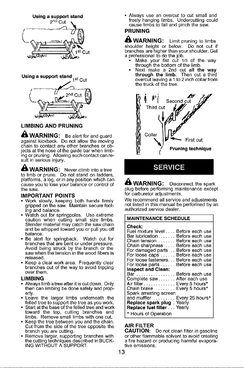
Using a support stand
2nd Cut
1st Cut
Using a support stand tst Cut
/
LIMBING AND PRUNING
_WARNING: Be alert for and guard
against kickback. Do not allow the moving
chain to contact any other branches or ob-
jects at the nose of the guide bar when limb-
log or pruning. Allowing such contact can re-
sult in serious injury.
_kWARNING: Never climb into atree
to limb or prune. Do not stand on ladders,
platforms, a log, or in any position which can
cause you to lose your balance or control of
the saw.
IMPORTANT POINTS
• Work slowly, keeping both hands firmly
gripped on the saw. Maintain secure foot-
ing and balance.
• Watch out for springpoles. Use extreme
caution when cutting small size limbs.
Slender material may catch the saw chain
and be whipped toward you or pull you off
balance.
• Be alert for springback. Watch out for
branches that are bent or under pressure.
Avoid being struck by the branch or the
saw when the tension in the wood fibers is
released.
• Keep a clear work area, Frequently clear
branches out of the way to avoid tripping
over them,
LIMBING
• Always limb atree after it iscut down. Only
then can limbing be done safely and prop-
erly.
• Leave the larger limbs underneath the
felled tree to support the tree as you work.
• Start at the base of the felled tree and work
toward the top, cutting branches and
limbs. Remove small limbs with one cut.
• Keep the tree between you and the chain.
Cut from the side of the tree opposite the
branch you are cutting.
• Remove larger, supporting branches with
the cutting techniques described in BUCK-
ING WITHOUT A SUPPORT.
• Always use an overcut to cut small and
freely hanging limbs. Undercutting could
cause limbs to fall and pinch the saw.
PRUNING
_WARNING: Limit pruning to limbs
shoulder height or below. Do not cut if
branches are higher than your shoulder. Get
a professional to do the job.
• Make your fist cut 1/3 of the way
through the bottom of the limb.
• Next make a 2nd cut all the way
through the limb. Then cut a third
overcut leaving a 1 to 2 inch collar from
the truck of the tree.
_Thi_rIdic Second cut'_'T'/i
Collar tit_/
'_l_JV '4"-- First cut
z Pruning technique
_WARNING:
Disconnect the spark
plug before performing maintenance except
for carburetor adjustments.
We recommend all service and adjustments
not listed in this manual be performed by an
authorized service dealer.
MAINTENANCE SCHEDULE
Check:
Fuel mixture level ....
Bar lubrication .....
Chain tension .....
Chain sharpness ,,
For damaged parts
For loose caps ....
For loose fasteners.
For loose parts ....
Inspect and Clean:
Bar ................
Complete saw .....
Air filter .............
Before each use
Before each use
Before each use
Before each use
Before each use
Before each use
Before each use
Before each use
Before each use
After each use
Every 5 hours*
Chain brake ........ Every 5 hours*
Spark arresting screen
and muffler ......... Every 25 hours*
Replace spark plug , Yearly
Replace fuel filter,., Yearly
* Hours of Operation
AIR FILTER
CAUTION: Do not clean filter in gasoline
or other flammable solvent to avoid creating
afire hazard or producing harmful evapora-
tive emissions.
13
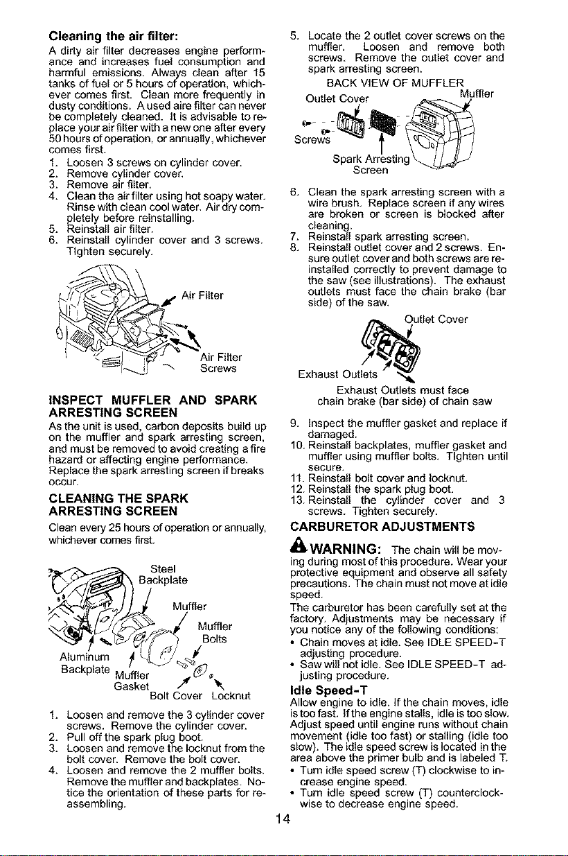
Cleaning the air filter:
A dirty air filter decreases engine perform-
ance and increases fuel consumption and
harmful emissions. Always clean after 15
tanks of fuel or 5 hours of operation, which-
ever comes first. Clean more frequently in
dusty conditions. A used aire filter can never
be completely cleaned. It is advisable to re-
place your air filter with a new one after every
50 hours of operation, or annually, whichever
comes first.
1. Loosen 3 screws on cylinder cover.
2. Remove cylinder cover.
3. Remove air filter.
4. Clean the air filter using hot soapy water.
Rinse with clean cool water. Air dry com-
pletely before reinstalling.
5. Reinstall air filter.
6. Reinstall cylinder cover and 3 screws.
Tighten securely.
ir Filter
i Air Filter
il_ -_ Screws
INSPECT MUFFLER AND SPARK
ARRESTING SCREEN
As the unit is used, carbon deposits build up
on the muffler and spark arresting screen,
and must be removed to avoid creating a fire
hazard or affecting engine performance.
Replace the spark arresting screen ifbreaks
occur.
CLEANING THE SPARK
ARRESTING SCREEN
Clean every 25 hours of operation or annually,
whichever comes first.
Steel
B°ckp,ate
Muffler
_/_>,/ Muffler
A,um+num ,°o,ts
Backplate _ / "_-J %_
Bolt Cover Locknut
1+ Loosen and remove the 3 cylinder cover
screws. Remove the cylinder cover.
2+ Pull off the spark plug boot.
3+ Loosen and remove the Iocknut from the
bolt cover. Remove the bolt cover.
4+ Loosen and remove the 2 muffler bolts+
Remove the muffler and backplates. No-
tice the orientation of these parts for re-
assembling.
5. Locate the 2 outlet cover screws on the
muffler. Loosen and remove both
screws. Remove the outlet cover and
spark arresting screen.
BACK VIEW OF MUFFLER
Outlet Cover Muffler
Spark Arresting \._ //_Jj._
Screen
6. Clean the spark arresting screen with a
wire brush. Replace screen if anywires
are broken or screen is blocked after
cleaning.
7. Reinstall spark arresting screen.
8. Reinstall outlet cover and 2 screws. En-
sure outlet cover and both screws are re-
installed correctly to prevent damage to
the saw (see illustrations). The exhaust
outlets must face the chain brake (bar
side) of the saw.
fiet Cover
Exhaust Outlets "_
Exhaust Outlets must face
chain brake (bar side) of chain saw
9. inspect the muffler gasket and replace if
damaged.
10. Reinstall backplates, muffler gasket and
muffler using muffler bolts+ Tighten until
secure.
11. ReinstaU bolt cover and Iooknut.
12. ReinstaU the spark plug boot.
13. ReinstaU the cylinder cover and 3
screws. Tighten securely.
CARBURETOR ADJUSTMENTS
_WARNING: The chain will be mov-
ing during most of this procedure. Wear your
protective equipment and observe all safety
precautions. The chain must not move at idle
speed.
The carburetor has been carefully set at the
factory. Adjustments may be necessary if
you notice any of the following conditions:
• Chain moves at idle. See iDLE SPEED-T
adjusting procedure.
• Saw will not idle. See IDLE SPEED-T ad-
justing procedure.
Idle Speed-T
Allow engine to idle. If the chain moves, idle
is too fast. If the engine stalls, idle istoo slow.
Adjust speed until engine runs without chain
movement (idle too fast) or stalling (idle too
slow). The idle speed screw islocated in the
area above the primer bulb and is labeled T.
• Turn idle speed screw (T) clockwise to in-
crease engine speed.
• Turn idle speed screw (T) counterclock-
wise to decrease engine speed.
14
Ifyourequirefurtherassistanceorareunsure
aboutperformingthisprocedure,contactyour
authorizedservicedealeror call
1-800-554-6723.
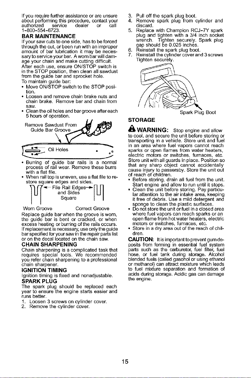
BAR MAINTENANCE
If your saw cuts to one side, has to be forced
through the cut, or been run with an improper
amount of bar lubrication it may be neces-
sary to service your bar. A worn bar will dam-
age your chain and make cutting difficult.
After each use, ensure ON/STOP switch is
in the STOP position, then clean all sawdust
from the guide bar and sprocket hole.
To maintain guide bar:
• Move ON/STOP switch to the STOP posi-
tion.
• Loosen and remove chain brake nuts and
chain brake. Remove bar and chain from
saw,
• Clean the oil holes and bargroove after each
5 hours of operation.
Remove Sawdust From _
_ Oil Holes = ,""_oO
• Burring of guide bar rails is a normal
process of rail wear. Remove these burrs
with a flat file.
• When rail top is uneven, use a flat file to re-
store square edges and sides.
_L_ File Rail Edges'_[1 [1
and Sides I U
Square I I
Worn Groove Correct Groove
Replace guide bar when the groove is worn,
the guide bar is bent or cracked, or when
excess heating or burring of the rails occurs,
If replacement is necessary, use only the guide
bar specified for your saw in the repair parts list
or on the decal located on the chain saw,
CHAIN SHARPENING
Chain sharpening is a complicated task that
requires special tools, We recommended
you refer chain sharpening to a professional
chain sharpener.
IGNITION TIMING
Ignition timing is fixed and nonadjustable.
SPARK PLUG
The spark plug should be replaced each
year to ensure the engine starts easier and
runs better.
1. Loosen 3 screws on cylinder cover.
2. Remove the cylinder cover.
3. Pull offthe spark plug boot.
4. Remove spark plug from cylinder and
discard.
5. Replace with Champion RCJ-7Y spark
plug and tighten with a 3/4 inch socket
wrench. Tighten securely. Spark plug
gap should be 0.025 inches.
6. Reinstall the spark plug boot.
7. ReinstaU the cylieder cover and 3 screws
Tighten securely.
Spark Plug Boot
STORAGE
_WARNING: Stop engine aed allow
to cool, and secure the unit before storing or
transporting in a vehicle. Store unit and fuel
in an area where fuel vapors cannot reach
sparks or open flames from water heaters,
electric motors or switches, furnaces, etc.
Store unit with all guards in place. Position so
that any sharp object cannot accidentally
cause injury to passersby. Store the unit out
of reach of children.
• Before storing, drain all fuel from the unit.
Start engine and allow to run until it stops.
• Clean the unit before storing. Pay particu-
lar attention to the air intake area, keeping
it free of debris. Use a mild detergent and
sponge to clean the plastic surfaces.
• Do not store the unit or fuel in adosed area
where fuel vapors can reach sparks or an
open flame from hot water heaters, electric
motors or switches, furnaces, etc.
• Store in a dry area out of the reach of chil-
dren.
CAUTION: It is important to prevent gum de-
posits from forming in essential fuel system
parts such as the carburetor, fuel filter, fuel
hose, or fuel tank during storage. Alcohol
blended fuels (called gasohol or using ethanol
or methanol) can attract moisture which leads
to fuel mixture separation and formation of
acids during storage. Acidic gas can damage
the engine.
15

TROUBLESHOOTING TABLE
WARNING: Always stop unit and disconnect spark plug before performing all of
the recommended remedies below except remedies that require operation of the unit.
TROUBLE CAUSE REMEDY
Engine will not 1. Ignition switch off. 1. Move ignition switch to ON.
start or will run 2. Engine flooded. 2. See "Difficult Starting" in
only a few Operation Section.
seconds after 3. Fuel tank empty. 3. Fill tank with correct fuel mixture.
starting. 4. Spark plug not firing. 4. InstaU new spark ping.
5. Fuel not reaching 5. Check for dirty fuel filter; replace.
carburetor. Check for kinked or split fuel line;
repair or replace.
Engine will 1. Carburetor requires 1. See "Carburetor Adjustment" in the
not idle adjustment. Service and Adjustments Section.
properly. 2. Crankshaft seals worn. 2. Contact an authorized service dealer.
Engine will not 1. Air filter dirty. 1. Clean or replace air filter.
accelerate, 2. Spark plug fouled. 2. Clean or replace plug and regap.
lacks power, 3. Chain brake engaged. 3. Disengage chain brake.
or dies under 4. Carburetor requires 4. Contact an authorized service dealer.
a load. adjustment.
Engine 1. Too much oil mixed with 1. Empty fuel tank and refill with
smokes gasoline, correct fuel mixture.
excessively.
Chain moves 1. See "Carburetor Adjustment" in the
at idle speed. Service and Adjustments Section.
2. Contact an authorized service dealer.
1. Idle speed requires
adjustment.
2. Clutch requires repair.
NEED ASSISTANCE?
Call 1-800-554-8723.
NEED SERVICE PART?
Contact your authorized service dealer.
ELECTROLUX HOME PRODUCTS, INC.,
warrants to the original purchaser that each
new Poulan PRO® brand gasoline chain saw
is free from defects in material and workmen-
ship end agrees to repair or replace under this
warranty any defective gasoline chain sew as
follows from the odginal date of purchase.
2 YEARS - Parts and Labor, when used for
Household purposes.
68 DAYS - Parts and Labor, when used for
Commercial, Professional, or income Produc-
ing purposes.
38 DAYS - Parts and Labor, if used for rental
purposes.
This warranty is not transferable and does not
cover damage or liabilitycaused by improper
handling, improper maintenance, or the use of
accessories and/or attachments not specifical-
ly recommended by ELEGTROLUX HOME
PRODUCTS, INC., for this chain sew. Addi-
tionally, this warranty does not cover damage
caused by improper handling, improper main-
tenance, or if the saw is altered in any way
which in our judgement affects itscondition or
operation. This warranty does not cover tune-
up, spark plugs, filters, starter ropes, starter
springs, chain sharpening, bars, chains, and
other parts which wear and require replace-
ment with reasonable use during the warranty
period. This warranty does not cover predeliv-
ery set-up, installation of guide bar and chain,
and normal adjustments explained in the in-
struction manual such as carburetor adjust-
ments and chain tension adjustments. This
warranty does not cover transportation costs.
THIS WARRANTY GIVES YOU SPECIFIC
LEGAL RIGHTS, AND YOU MAY HAVE
OTHER RIGHTS WHICH VARY FROM
STATE TO STATE.
NO CLAIMS FOR CONSEQUENTIAL OR
OTHER DAMAGES WILL BE ALLOWED,
AND THERE ARE NO OTHER EXPRESS
WARRANTIES EXCEPT THOSE EXPRESS-
LY STIPULATED HEREIN.
SOME STATES DO NOT ALLOW LIMITA-
TIONS ON HOW LONG AN IMPLIED WAR-
PANTY LASTS OR THE EXCLUSION OR
LIMITATIONS OF INCIDENTAL OR CONSE-
QUENTIAL DAMAGES, SO THE ABOVE
LIMITATIONS OR EXCLUSION MAY NOT
APPLY TO YOU.
The policy of ELECTROLUX HOME PROD-
UCTS, INC., is to continoously improve its
products. Therefore, ELECTROLUX HOME
PRODUCTS, INC., reserves the right to
change, modify, or discontinue models, de-
signs, specifications, and accessoites of all
products at any time without notice or obliga-
tion to any purchaser.
16

YOUR WARRANTY RIGHTS AND OB-
LIGATIONS: The U S Environmental
Protection Agency, Environment Canada
and ELECTROLUX HOME PRODUCTS,
INC., are pleased to explain the emissions
control system warranty on your year
2002-2004 small off-road engine. ELEC-
TROLUX HOME PRODUCTS, INC., must
warrant the emission control system on your
small off-road engine for the periods of time
listed below provided there has been no
abuse, neglect, or improper maintenance of
your smaU off-road engine. Your emission
control system includes parts such as the
carburetor and the ignition system. Where a
warrantable condition exists, ELECTRO-
LUX HOME PRODUCTS, INC., will repair
your small off-road engine at no cost to you.
Expenses covered under warranty include
diagnosis, parts and labor. MANUFACTUR-
ER S WARRANTY COVERAGE: If any
emissions related part on your engine (as
listed under Emissions Control Warranty
Parts List) is defective ora defect in the ma-
terials or workmanship of the engine causes
the failure of such an emission related part,
the part will be repaired or replaced by
ELECTROLUX HOME PRODUCTS, INC.
OWNER'S WARRANTY RESPONSIBILI-
TIES: As the small off-road engine owner,
you are responsible for the performance of
the required maintenance listed in your in-
struction manual. ELECTROLUX HOME
PRODUCTS, INC., recommends that you
retain all receipts covering maintenance on
your small off-road engine, but ELECTRO-
LUX HOME PRODUCTS, INC., cannot
deny warranty solely for the lack of receipts
or for your failure to ensure the performance
of all scheduled maintenance. As the small
off-road engine owner, you should be aware
that ELECTROLUX HOME PRODUCTS,
INC., may deny you warranty coverage if
your small off-road engine or a part of it has
failed due to abuse, neglect, improper main-
tenance, unapproved modifications, or the
use of parts not made or approved by the
odgina[ equipment manufacturer. You are
responsible for presenting your small off-
road engine to an ELECTROLUX HOME
PRODUCTS, INC., authodzed repair center
as soon as a problem exists. Warranty re-
pairs should be completed in a reasonable
amount of time, not to exceed 30 days. If you
have any questions regarding your warranty
rights and responsibilities, you should con-
tact your nearest authorized service center
or call ELECTROLUX HOME PRODUCTS,
INC., at 1-800-554-6723. WARRANTY
COMMENCEMENT DATE: The warranty
period begins on the date the small off-road
engine is purchased. LENGTH OF COVER-
AGE: This warranty shall be for a period of
two years from the initial date of purchase.
WHAT IS COVERED: REPAIR OR RE-
PLACEMENT OF PARTS. Repair or re-
fPolaCementof any warranted part will be per-
rmed at no charge to the owner at an
approved ELECTROLUX HOME PROD-
UCTS, INC., servicing center. If you have
any questions regarding your warranty
rights and responsibilities, you should con-
tact your nearest authorized service center
or call ELECTROLUX HOME PRODUCTS,
INC., at 1-800-554-6723. WARRANTY
PERIOD: Any warranted part which is not
scheduled for replacement as required
maintenance, or which is scheduled only for
regular inspection to the effect of "repair or
replace as necessary" shall be warranted for
2 years. Any warranted part which is sched-
uled for replacement as required mainte-
nance shall be warranted for the period of
time up to the first scheduled replacement
point for that part. DIAGNOSIS: The owner
shall not be charged for diagnostic labor
which leads to the determination that a war-
ranted part is defective ifthe diagnostic work
isperformed at an approved ELECTROLUX
HOME PRODUCTS, INC., servicing center.
CONSEQUENTIAL DAMAGES: ELEC-
TROLUX HOME PRODUCTS, INC., may
be liable for damages to other engine com-
ponents caused by the failure of awarranted
part still under warranty. WHAT IS NOT
COVERED: All failures caused by abuse,
neglect, or improper maintenance are not
covered ADD-ON OR MODIFIED PARTS:
The use of add-on or modified parts can be
grounds for disallowing a warranty claim.
ELECTROLUX HOME PRODUCTS, INC.,
is not liable to cover failures of warranted
_arts caused by the use of odd-on or modi-
ed parts. HOW TO FILE A CLAIM: If you
have any questions regarding your warranty
rights and responsibilities, you should con-
tact your nearest authorized service center
or call ELECTROLUX HOME PRODUCTS,
INC., at 1-800-554-6723. WHERE TOGET
WARRANTY SERVICE: Warranty services
or repairs shall beprovided at all ELECTRO-
LUX HOME PRODUCTS, INC., service
centers. Call 1-800-554-6723. MAINTE-
NANCE, REPLACEMENT AND REPAIR
OF EMISSION RELATED PARTS: Any
ELECTROLUX HOME PRODUCTS, INC,
approved replacement part used in the per-
formance of any warranty maintenance or
repair on emission related parts will be pro-
vided without charge to the owner if the part
is under warranty. EMISSION CONTROL
WARRANTY PARTS LIST: Carburetor,
Ignition System: Spark Plug covered up to
maintenance schedule), Ignition Module.
MAINTENANCE STATEMENT: The owner
is responsible for the performance of all re-
quired maintenance as defined in the in-
struction manual
17

The information on the product label indicates which standard your engine is certified.
Example: (Year) EPA Phase 1 or Phase 2 and/or CALIFORNIA,
This engine is certified to be emissions compliant for the following use:
[] Moderate (50 hours)
[]Intermediate (125 hours)
[] Extended (300 hours)
18
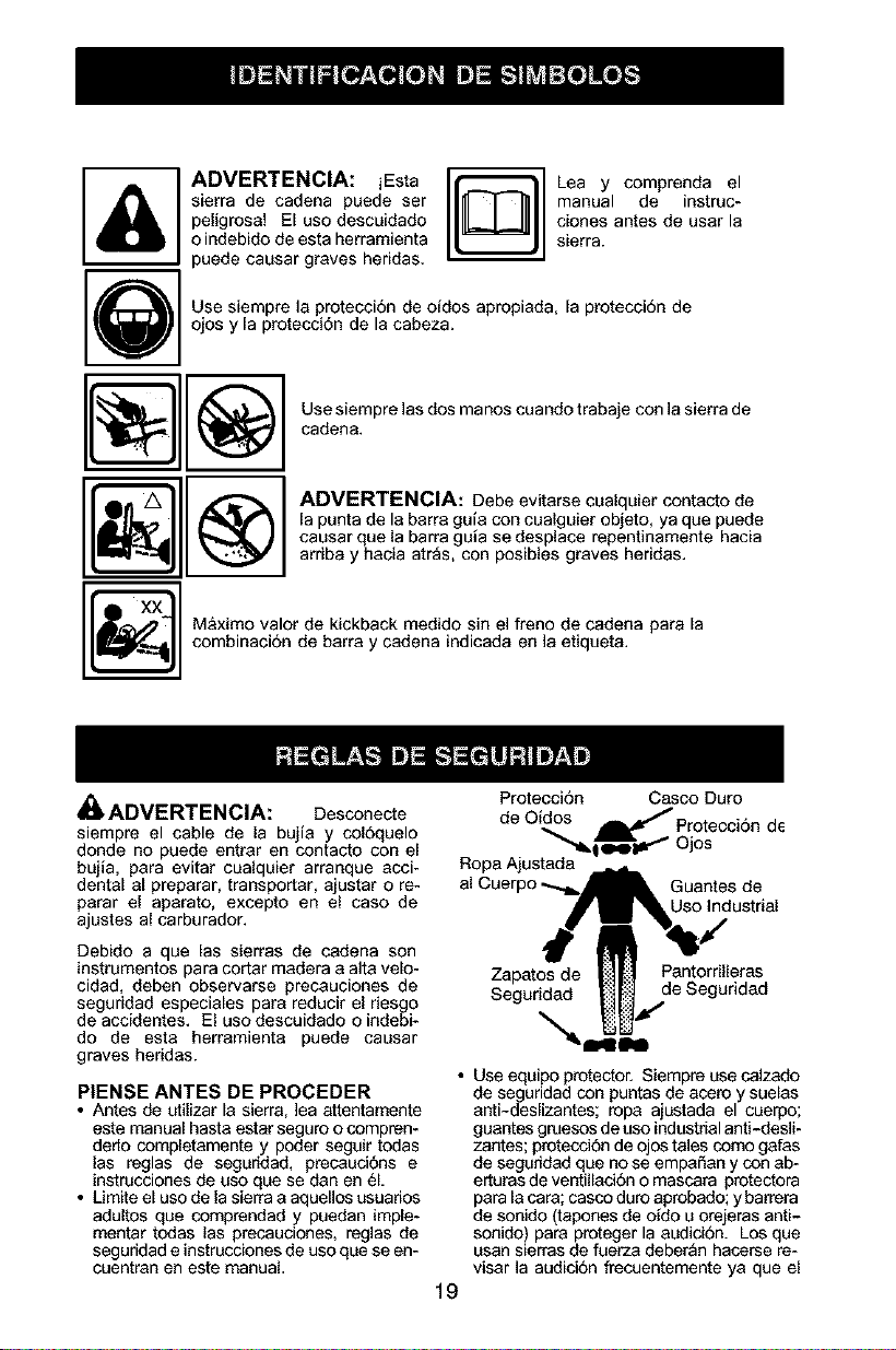
ADVERTENCIA: iEsta
sierra de cadena puede ser
peligrosa! El uso descuidado
o indebido de esta herramienta
puede causar graves heddas.
Lea y comprenda el
manual de instruc-
clones antes de user la
sierra.
Use siempre la protecci6n de oidos apropiada, la protecci6n de
ojos y la protecci6n de la cabeza.
Use siempre las dos manos cuando trabaje con la sierra de
cadena.
ADVERTENCIA: Debe evitarse cualquier contacto de
[a punta de le berre guie con cualguier objeto, ya que puede
causar que la barra guia se desplace repentinamente hacia
ardba y hacia atr_s, con posibles graves heddas.
_] &ximo valor de kickback medido sin el freno de cadena para la
combinacion de barra y cadena indicada en la etiqueta.
_,ADVERTENCIA: Desconecte
siempre el cable de la bujia y col6quelo
donde no puede entrar en contacto con el
bujla, para evitar cualquier arranque acci-
dental al preparar, transporter, ajustar o re-
parar el aparato, excepto en el caso de
ajustes al carburador.
Debido a que las sierras de cadena son
instrumentos para cotter madera a alta velo-
cidad, deben observarse precauciones de
seguddad especieles pare reducir el desgo
de accidentes, El uso descuidado o indebi-
do de este herramienta puede causer
graves heddas.
P|ENSE ANTES DE PROCEDER
• Antes de utilizar la sierra, lea attentamente
este manual haste estar seguro o compren-
dedo completamente y poder seguir todas
las reglas de seguridad, precauci6ns e
instrucciones de uso que se dan en 61.
• Umite el uso de lasierra a aquellos usuados
adultos que comprendad y puedan imple-
mentar todas las precauciones, reglas de
seguridad e instrucciones de uso que se en-
cuentran en este manual.
Protecci6n Casco Duro
de Oidos
Protecci6n de
""_l g'W _ Ojos
Ropa Ajustada
Guantes de
Uso Industrial
19
Zapatos de Pantorrilleras
Seguridad de Seguddad
• Use equipo protector, Siempre use caIzado
de seguridad con puntas de acero y suelas
anti-deslizantes; rope ajustada el cuerpo;
guantes gruesos de uso industrial anti-desli-
zantes; protecci6n de ojos tales como galas
de seguddad que no se empaSan y con ab-
erturas de ventillaci6n o mascara protectora
para la care; casco duro aprobado; y barrera
de sonido (tapones de ofdo u orejeras anti-
sonido) pare proteger la audicion. Los que
usan sierras de fuerza deber_n hacarse re-
viser ]a audici6n frecuentemente ya que el
ruido de las sierras de cadena puede daftar
los oidos.
• Mantenga todas las partes del cuerpo aleja-
das de la cadena siempre que el motor est6
en funcionamiento.
• Mantenga a los niftos, espectadores y ani-
males a una distancia minima de 10 metros
(30 pies) del &rea de trabajo o cuando esta
hacienco arrancar el motor.
• No levante ni opera la sierras de cadena
cuando esta faigado, enfermo, ansioso o si
ha tornado alcohol, drogas o remedios. Es
imprescindible que ed. est_ en buenas con-
diciones flsicas yalerta mentalmente. Si ud.
sufre de cualquier condicion que pueda em-
peorar con el trabajo arduo, ases6rese con
su m6dico.
• No ponga en maroha la sierra sin tener un
_rea de trabajo despejada, superficie est-
able para pararse y, siesta derrubando
_rboles, un camino predeterminado de re-
troceso.
USE LA SIERRA OBSERVANDO
TODOS LOS PROCEDIMIENTOS
DE SEGURIDAD
• Mantenga Ins dos manos en las manijas
siempre que el aparato est6 en march& El
uso del aparato con una sola mano puede
causar graves heridas al usuario, a los asis-
tentes, o a los espectadores. Las sierras de
cadena est&n diseSadas para que se las use
con las dos manos en todo momento.
• Haga uso de la sierra de cadena 0nicamente
en lugares exteriores bien ventillados.
• No haga aso de la sierra desde las escaler-
as port,tiles ni de los arboles.
• Aseg0rese de que lacadena no vaya a hac-
er contacto con ning0n objeto antes de pon-
eren marcha el motor. Nunca intente hacer
arrancar la sierra con la barra quia en un
code.
• No aplique presi6n a la sierra al final de los
codes. Aplicar presi6n puede hacer que
pierda el control al completaPse el code.
• Pare el motor antes de apoyar la sierra en
ningSn lado.
• No ponga en funcionamiento ]asierra de ca-
dena si est& daSada, incorrectamente ajus-
tad& o si no est_ armada completa y segu-
ramente. Siempre cambie el protector de
mano immediatamente si _sta queda daf_a-
do, roto, o se sale pot cualquier motivo.
• Cuando cargue la sierra de cadena en las
manos, h&galo con el motor parado, el silen-
ciador alejado del cuerpo, y la cadena hacia
atras y cubieda con un estuche.
MANTENGA LA SIERRA EN BUE-
NAS CONDICIONES DE FUNC-
TIONAMIENTO
• Lleve la sierra de cadena a un distdbuidor
autodzado del servicio para que haga todo
servicio menos aquellos procedimientos lis-
tados en la aecci6n de mantenimiento de
este manual. Por ejempplo, si se usan her-
ramientas que no corresponden para retirar
o sostener el volante al hacer servicio al em-
brague, pueden ocurdr daSos estructurales
al volante y causar que reviente.
• AsegOrese de que la cadena se detenga por
completo cuando se suelta el gatillo. Para
hacer correcciones, vea los AJUSTES AL
CARBURADOR.
• Nunca haga modificaciones de ninguna in-
dole a su sierra.
• Mantengalas manijassecas, Iimpiasylibres
de aceite o de mezcia de combustible.
• Mantenga las tapas y los fijadores blen fijos.
• Use exclusivamente los accesorios y re-
puestos Poulan PRO_> recomendados.
MANEJE EL COMBUSTIBLE CON
EXTREMO CUIDADO
• No fume mientras trabaja con elcombustible
ni cuando esta haciendo uso de la sierra.
• Elimine todas las posibles fuentes de chis-
paso llamas en las _reas deride se mezcla o
viede el combustible. No debe haber el fu-
mar, llamas abiertas, o trabajo que podda
causar chispas. Permita que el motor es fdo
antes de reaprovisionar de combustible.
• Mezcle y vieda el combustible afuera y use
recipiente aprobado para combustibles y
marcado como tal. Limpie todos los der-
rames de combustible.
• AI6jese a por Io mendos 3 metros (10 pies)
del lugar de abastecimiento antes de porter
el motor en march&
• Apague el motor y deje que la sierra se
enfrie en un lugar Iibre de substancias com-
bustibles y no sobre hojas secas, paja, pa-
pel, etc. Retire la tapa lentamente y reabas-
tezca el aparato.
• Guarde el aparato en un espaduo fresco,
seco y bien ventilado donde los vapores del
combustible no pueden entrar en coatacto
con chispas ni llamas ablertas provenientes
de termotangues, motores o interruptores
electricos, calefactores centrales, etc.
RECULADA
ADVERTENCIA: Evite reculada le
pueden causar graves heridas Reculada
es el movimiento hacia el frente hacia atr_s
o r_pidamente hacia adelante, esto puede
ocurrir cuando la punta de la barra guia de la
sierra de cadena entra en contacto con cual-
quier objeto como puede ser otra rama o
tronco, o cuando la madera se cierra y atas-
ca mientras se hace el corte. El entrar en
contacto con alg0n objeto extraSo a la mad-
era le puede causar al usuario la perdida del
control de la sierra de cadena.
• La Reculada Rotacional puede acontecer
cuando la cadena en movimiento entra en
contacto con algt_n objeto e? la parte superi-
or de la punta de la barra guJa puede caasar
que la cadena entre al material y se detenga
porun instante. El rasultadoes una reaccion
inversa, a velocidad de rel_mpago, que hace
racular la barra gufa hacia arriba y hacia
atr_s hacia el usuario.
• La Reculada pot Atasco acontecen cuan
do la madera secierra yetasca lacadena en
movimiento en el code a Io largo de la parte
superior de la barra guia y la cadena se de-
tiene repentinamente Esta detenei6n re-
pentina de la cadena tiene como resultado
20
una inversiSn de lafuerza de la cadena usa-
da para cortar madera y caosa que la sierra
se mueva en sentido opuesto al de la rota-
cion de la cadena. La sierra directamente
hacia atras en direcci6n al esuario.
° La Reculada pot Impulsibn puede acon-
tecer cuando Iseadena en movimiento entra
en contacto con alg_n objeto extrafio a la
madera en el corte a Io largo de la parte infe-
rior de la barra gula y la cadena se detiene
repentinamente. Esta detencion repentina
de la cadena tira de la sierra adelante y lejos
del usuano y podria hacer facilmente al
usuario perder el control de la sierra.
Para Evitar la Reculada por Atasco:
• Mant_ngase completamente conciente de
toda situacion u obstrucci6n que pueda hac-
er que el material presione la cadena en la
parte superior o que pueda parar Is cadena
de cualqeier otro modo.
• No corte mas de un tronco a la vez.
• No retuerza la sierra al retirar la barra de
un corte ascendiente cuando est& seccio-
nando troncos.
Para Evitar laReculada pot Impuleibn:
• Empiece tedo corte con el motor acelerado a
fondo y con la coja de la sierra apoyada con-
tra Is madera.
• Use cutlas de pl_stico o de madera (nunca
de metal) para mantener abierto el corte.
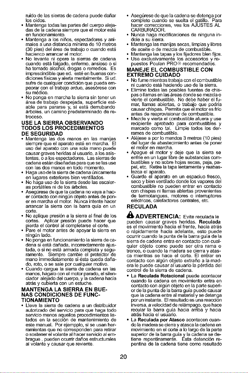
\ 3, Trayectoria de la
_'_,_ _ Reculada
Despeje el Area de Trabajo
REDUZCA LAS PROBABILIDADES
DE RECULADA
• Reconozca que la sierra puede recular. Con
una comprensi6n basica del fenomeno de la
reculada de la sierra, ud. puede reducir el
elemento de sorpresa que contribuye a los
accidentes.
• Nunca permita que la cadena en movi-
miento toque ningQn objeto en la punta de
labarra gu_a.
• Mantenga el _rea de trabajo libre de obstruc-
ciones como por ejemplo otros arboles, ra-
mas, piedras, cereas, tocones, etc. Elimine
o evite todo obst&colo que la sierra pueda
enfrentar al cortar determinado trenco o
ram& AI cortar una ram& no deje la barra
guia entrar en contacto con otra rama o otros
objetos alrededor.
• Mantenga la sierra afilada y con la tensiSn
correct& Las cadenas con poco filo o nojas
incrementan la probabilidad de reculada.
Siga las instrucciones del fabdcante para aft-
lar y efectuar mantenimiento de la cadena.
Verifique la tensi6n a intervalos regulares
con el motor parado, nunca en marcha.
Aseg6rese de que las tuercos de la freno de
cadena est6n ajustadas firmemente.
• Empiece y efectt3e la totalidad de cada corte
con el acelerador a fondo. Si la cadena se
est_ moviendo a una velocidad menor que la
m&xima, hay mas probabilidad de que la
sierra recule.
• Corte _]nicamente un trenco a la vez.
• Use cuidado extremo al entrar de nuevo en
un corte ya empezado.
• No intente hacer cortes empexando con la
punta de la barra (cortes de taladro).
• Tenga cuidado con troncos que se despla-
zany con las dem&s fuerzas que poddan
cerrar en corte y apretar la cadena o caer
sobre ella.
• Use la Barra Guia Reducidora de Recela-
das y la Cadena Minimizadora de Recula-
das.
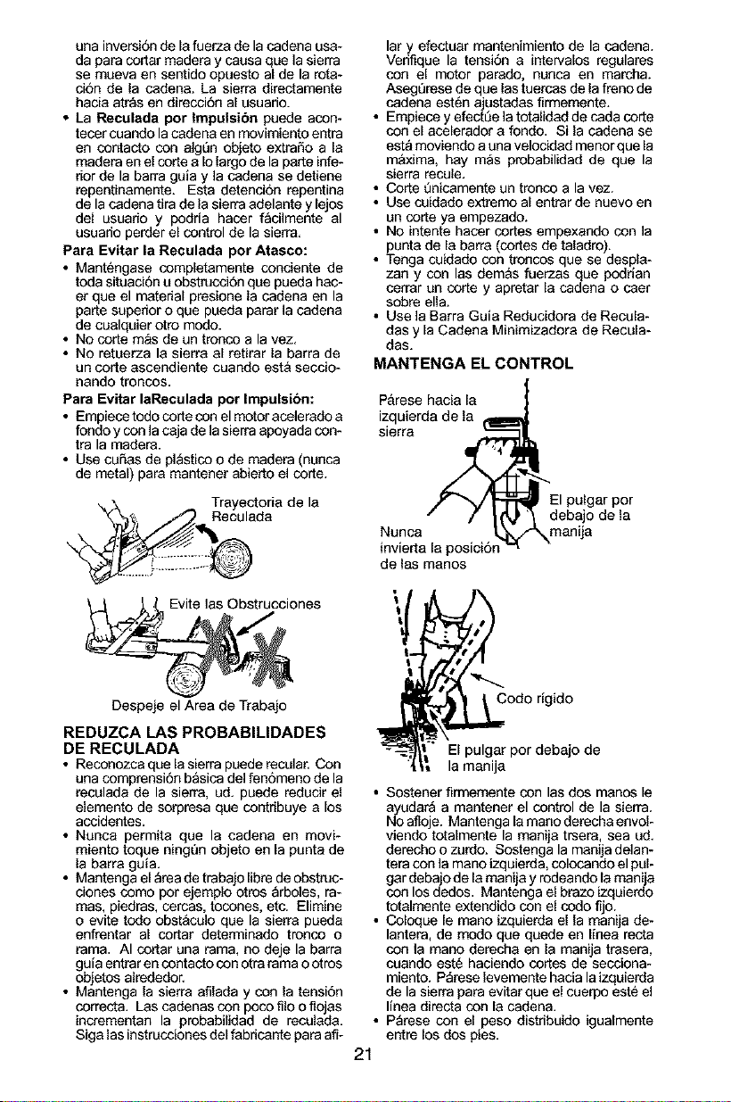
MANTENGA EL CONTROL
P&rese hacia la
izquierda de la
sierra
debajo de la
Nunca manija
invierta la pos_cion
de las manos
la manija
• Sostener firmemente con las dos manos le
ayudara a mantener el control de la sierra.
No afloje. Mantenga lamano derecha envol-
viendo totalmente la manija trsera, sea ud.
derecho o zurdo. Sostenga la manija delan-
tera con la mano izquierda, colocando elpel-
gar debajo de la manija y redeando la manija
con los dedos. Mantenga el brazo izquierdo
totalmente extendido con el codo fijo.
• Coloque le mano izquierda el la manija de-
lantera, de modo qee qeede en Ifnea recta
con la mano derecha en la manija trasera,
coando est_ haciendo cortes de secciona-
miento. P_rese levemente hacia la izquierda
de la sierra para evitar que el cuerpo est_ el
linea directa con la cadena.
• P_rese con el peso distribuido igualmente
entre los dos pies.
21
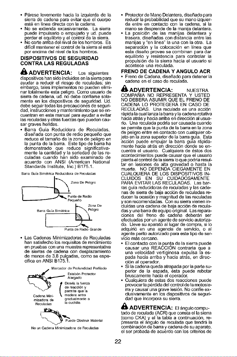
• Parese levemente hacia la izquierda de la
sierra de cadena para evitar que el cuerpo
est6 en llnea directa con la cadena.
• No se extienda excesivamente. La sierra
puede impulsario o empujado y ud. puede
perder el equilibrio y el control de la sierra.
• No corte aniba del nival de los hombros. Es
dificil mantener el control de la sierra si est_
per endma del nivel de los hombros.
DISPOSITIVOS DE SEGURIDAD
CONTRA LAS REGULADAS
i_ ADVERTENClA: Los siguientes
dispositivos han sido incluidos en la sierra para
ayudar a reducir el riesgo de reculadas; sin
embargo, tales implementos no pueden elimi-
nar totalmente esta peligro. Como usuario de
sierra de cadena, ud. no debe confiarse sola-
mente en los dispositivos de seguridad. Ud.
debe seguir todas las precauciones de seguri-
dad, instrucciones y mantenimiento qee se en-
cuentran en este manual para ayudar a evitar
las reculadas y otras fuerzas que pueden cau-
sar graves heridas.
• Barra Guia Reducidora de Reculadas,
diseSada con punta de redio pequeSo que
reduce el tamaSo de la zona de peligro en
la punta de la barra. Este tipo de barra ha
demonstrado que reduce significativa-
mente la cantidad y la seriedad de las re-
culadas cuando han sido examinado de
acuerdo con ANSI (American National
Standards Institute, Inc.) B175.1.
Barra GLtia Sim_trica Reducidora de Reculadas
Zona De Pelig_o
PLtnta de Radio
PequeSo
Z_na De
B_ra Gu{a Sim6tdca Pelig_o
Punta de Radio Grande
• Las Cadenas Minimizadoras de Reculadas
han satisfecho los requisitos de rendimiento
en pruebas con una muestra representativa
de sierras de cadena con desplazamiento
de menos de 3,8 pulgadas, como se espe-
cifica en ANSI B175.1.
Marcador de }_rofundidad Pe_lado
J
_ _ _ J Estab6n Protector
_-"'_ Alargado
L_ ! Desvia la fuerza
de reacci6n y
permite que la
Cadena Mini- \ madera entre
mizadora de gradualmente a
Reculadas la cuchilia
_Puede Obstruir MatedN
No un Cadena Minimizadora de Reculadas
• Protector de Mano Delantera, diseSado para
redecir la probabilidad que su mane izquier-
da entre en contacto con la cadena, si la
mano se desprende de la manija delantera.
• La posici6n de las manijas delantera y
trasera, diseSadas con distancia entre las
manijas y "en linea" la una con laotra. La
separaci6n y la colocaci6n en linea que
este diseSo provee se combinan para dar
equilibrio y resistencia para controlar la
propulsion de la sierra hacia el usuado si
acontece una reculada.
FRENO DE CADENA Y ANGULO ACR
• Freno de Cadena, diseSado para detener la
cadena en el case de reculada.
ADVERTENCIA: NUESTRA
COMPA_IIA NO REPRESENTA Y USTED
NO DEBERA ASUMIR QUE EL FRENO DE
CADENA LO PROTEGERA EN CASO DE
RECULADAS. Una reculada es una acci6n
r_pida la cual lanza la barra y lacadena rotativa
hacia atras y hacia arriba en direcci6n al usua-
rio. Una reculada podria set causada cuando
se permite que la punta de la barra en la zona
de peligro entre en contacto con cualquier ob-
jeto en la zona superior de la barra g.uia. Esta
accion puede empujar la barra guia rapida-
mente hacia atr_s en direcci6n donde se en-
coentra el usuario. Cualquiera de estos dos
acoetecimieetos puede caosar que el usuario
pierda el control de lasierra Ioque podria resul-
tar en lesiones de alta gravedad o hasta la
muerte. NO DEPENDA CIEGAMENTE EN
CUALQUIERA DE LOS DISPOSlTIVOS IN-
CLUIDOS EN SU CUIDADOSAMENTE
PARA EVlTAR LAS RECULADAS. Las bar-
ras guia reducidoras de reculadas y las cade-
nas de sierra de baja acci6n de reculadas re-
ducen la ocasi6n y magnitud de las reculadas
y son recomendadas. Con su sierra vienen in-
cluidas una cadena de baja acci6n de recula-
das y una barra de equipo original. Las repara-
clones del freno de cadena deber_n ser
efectuadas por un agente de servicio autoriza-
do. Lleve su aparato al lugar de compra, si Io
adquirio en una agencia de servicio, o al
agente perito autodzado para este tipo de ser-
vicio mas cercano.
• El contacto con la punta de la sierra puede
causar una REACCION contraria que a
una velocidad vertiginosa expulsa la es-
pada hacia arriba y hacia atr_s, en direc-
ci6n al operador.
• Si la cadena queda atrapada pot la parte su-
perior de la espada, 6sta puede rebotar
bruscamente hacia el operador.
• Cualquiera de estas dos reacciones puede
provocar la p6rdida del control de lamotosie-
rray caosar una grave lesi6n. No confie ex-
closivamente en los dispositivos de seguri-
dad que incorpora su sierra.
_, ADVERTENCIA: Elangulocompu-
tado de reculada (ACR) qee consta el la sierra
(como CKA) y el la tabla a continuacion, re-
presenta el _ngulo de recolada que tendra la
combinaci6n de barra y cadena de su aparato,
el ser probada de acuerdo con los cdtedos de
22
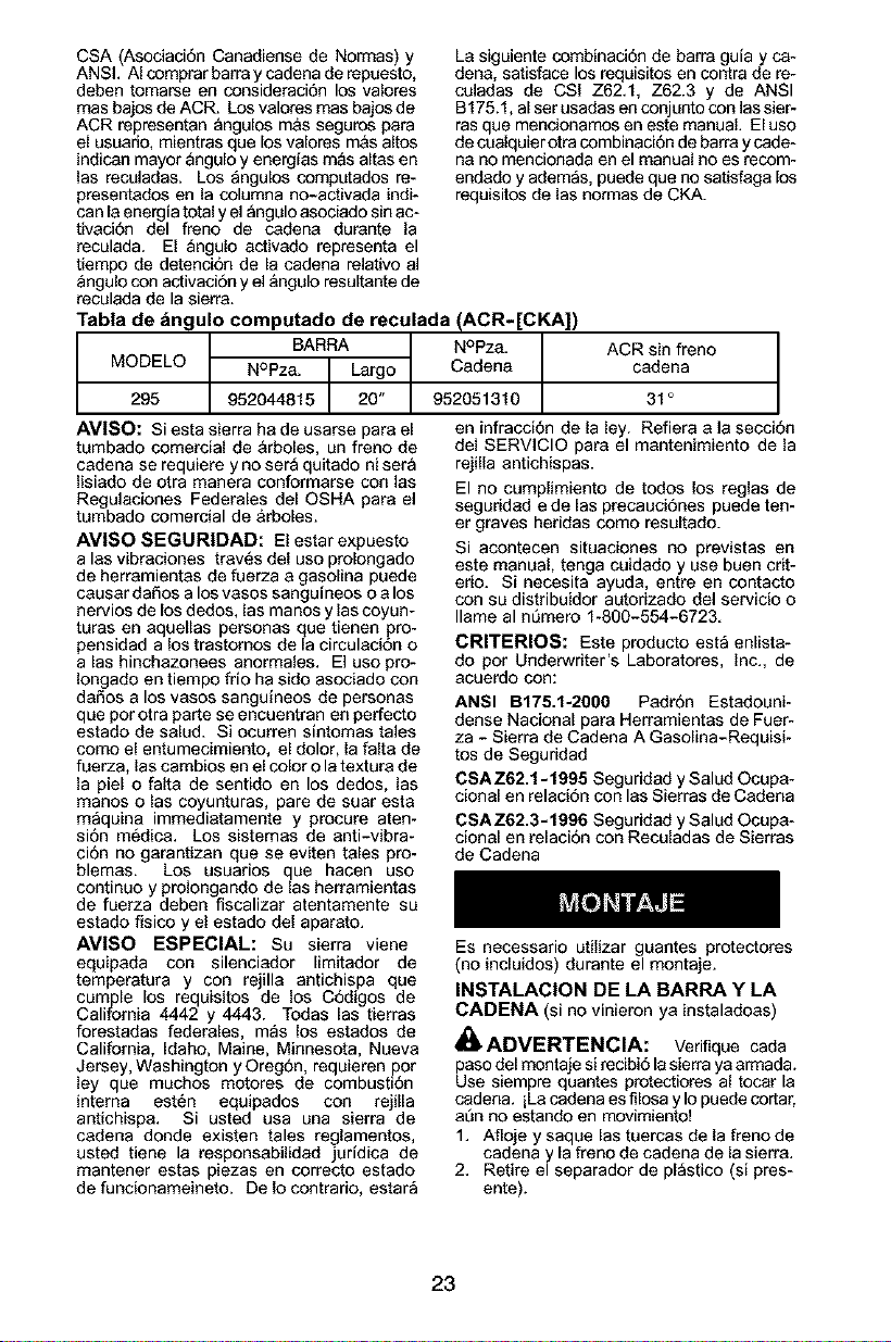
CSA (Asociaci6n Canadiense de Normas) y
ANSI. AI comprar barra y cadena de repuesto,
deben tomarse en consideraci6n los valores
mas bajos de ACR. Los valores mas bajos de
ACR representan _ngulos m&s seguros para
el usuado, mientras que los valores m&s altos
indican mayor Qngulo y energfas mQs altas en
las reculadas. Los angulos computados re-
presentados en la columna no-activada indi-
can la energia total y el _ngulo asociado sin ac-
tivaci6n del freno de cadena durante la
reculada. El Qngulo activado representa el
tiempo de detencion de la cadena relativo al
_ngulo con activaci6n y el&ngulo resultante de
reculada de la sierra.
Tabla de bngulo computado de reculada (ACR-[CKA])
BARRA NOpza.
MODELO NOPza._ _ Cadena
295 952044815 95205131 O
La siguiente combinad6n de barra guia y ca-
den& satisface los requisitos en contra de re-
coladas de CSI Z62.1, Z62.3 y de ANSI
B175.1, alser usadas en conjunto con las sier-
ras que mencionamos en este manual. El uso
de coalquier otra combinaci6n de barra y cade-
na no mencionada an el manual no es recom-
endado y ademas, puede que no satisfaga los
requisitos de las normas de CKA.
ACR sin freno
cadena
31 °
AVI80: Siesta sierra ha de usarse para el
tumbado comercial de &rboles, un freno de
cadena se requiere y no sera quitado ni sera
Iisiado de otra manera conformarse con las
Regulaciones Federales del QSHA para el
tumbado comercial de &rboles.
AVlSO SEGURIDAD: El estar expuesto
alas vibraciones traves del uso prolongado
de herramientas de fuerza a gasolina puede
causar daSos a los vasos sanguineos o a los
nervios de los dedos, las manos y las coyun-
turas en aquellas personas que tienen pro-
pensidad a los trastomos de la circulaci6n o
a las hinchazonees anormales. El uso pro-
Iongado en tiempo frio ha sido asociado con
daSos a los vasos sangufneos de personas
que por otra parte se encuentran en perfecto
estado de salud. Si ocurren sintomas tales
como el entumecimiento, el dolor, la falta de
fuerza, las cambios en elcolor o la textura de
la piel o falta de sentido en los dedos, las
manos o las coyunturas, pare de suar esta
maquina immediatamente y procure aten-
sion m6dica. Los sistemas de anti-vibra-
cion no garantizan que se eviten tales pro-
blemas. Los usuarios que hacen uso
continuo y prolongando de las herramientas
de fuerza deben fiscalizar atentamente su
estado fisico y el estado del aparato.
AVISO ESPECIAL: Su sierra viene
equipada con silenciador Iimitador de
temperatura y con rejilla antichispa que
cumple los requisitos de los C6digos de
California 4442 y 4443. Todas las tierras
forestadas federales, m_s los estados de
California, Idaho, Maine, Minnesota, Nueva
Jersey, Washington y Oreg6n, requieren por
ley que muchos motores de combusti6n
interna est_n equipados con rejilla
antichispa. Si usted usa una sierra de
cadena donde existen tales reglamentos,
usted tiene la responsabilidad juridica de
mantener estas piezas en correcto estado
de funcionameineto. De Io contrario, estar_
en infracci6n de la ley. Refiera a la secci6n
del SERVICIO para el mantenimiento de la
rejilla antichispas.
El no cumplimiento de todos los reglas de
seguridad e de las precauci6nes puede ten-
er graves heridas como resultado.
Si acontecen situaciones no previstas en
este manual, tenga cuidado y use buen crit-
erio. Si necesita ayuda, entre en contacto
con su distribuidor autodzado del servicio o
flame al nl3mero 1-800-554-6723.
CRITERIOS: Este producto esta enlista-
do por Underwdter's Laboratores, Inc., de
acuerdo con:
ANSI B175.1-2OOO Padron Estadouni-
dense Nacional para Herramientas de Fuer-
za - Sierra de Cadena A Gasolina-Requisi-
tos de Seguridad
CSAZ62.1-1995 Seguridad y Salud Ocupa-
cional en relaci6n con las Sierras de Cadena
CSAZ62.3-1996 Seguddad y Salud Ocopa-
cional en relacion con Reculadas de Sierras
de Cadena
Es necessario utilizar guantes protectores
(no incluidos) durante el montaje.
INSTALACION DE LA BARRA Y LA
CADENA (si no vinieron ya instaladoas)
_ ADVERTENCIA: Verifique cada
paso del montaje si recibi6 la sierra ya armada.
Use siempre quantes protectiores al tocar la
cadena, iLa cadena es filosa y Io puede cortar,
at3nno estando en movimiento!
1. Afloje y saque las tuercas de la freno de
cadena y la freno de cadena de la sierra.
2. Retire el separador de pl_stico (si pres-
ente).
23
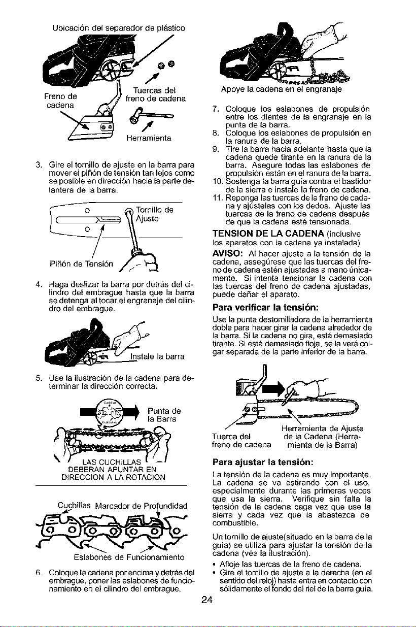
Ubicaci6n del separador de pl&stico
@O
/I
Tuercas del
Freno de freno de cadena
cadena
Herremienta
3. Gire el tornillo de ajuste en la barra para
mover el pifi6n de tensi6n tan lejos como
se posible en direcci6n hacia la parte de-
lantera de la barra.
o AjT,=,,o,e
Pi_6n de Tensi6n //_
4. Haga deslizar la barra por detras del ci-
lindro del embrague hasta que la barra
se detenga al tocar el engranaje del cilin-
dro del embrague.
_e la barra
5. Use la ilustraci6n de la cadena para de-
terminar la direcci6n correcta.
Punta de
la Barra
DEBERAN APUNTAR EN
DIRECCION A LA ROTACION
Cuchillas Marcador de Profundidad
Eslabones de Funcionamiente
6. Coloque la cadena por encima y detras del
embrague, poner las eslabones de funcio-
namiento en el cilindro del embrague.
Apoye la cadena en el engranaje
7. Coloque los eslabones de propulsi6n
entre los dientes de la engranaje en la
punta de la barra.
8. Coloque los eslabones de propulsi6n en
la ranura de la barra.
9. Tire la barra hacia adelante hasta que la
cadena quede tirante en la ranura de la
barra. Asegure todas las eslabones de
propulsi6n estan en el ranura de la barra.
10. Sostenga la barra guia contra el bastidor
de la sierra e instale la freno de cadena.
11. Reponga las tuercas de la freno de cade-
nay ajt)stelas con los dedos. Ajuste las
tuercas de la freno de cadena despu6s
de que [a cadena est6 tensionada.
TENSION DE LA CADENA (inclusive
los aparatos con la cadena ya instalada)
AMISO: AI hacer ajuste a la tensi6n de la
cadena, asseg_rese que las tuercas del fre-
no de cadena est6n ajustadas a mano _nica-
mente. Si intenta tensionar la cadena con
las tuercas del freno de cadena ajustadas,
puede daSar el aparato.
Para verificar la tensi6n:
Use la punta destornilladora de la herramienta
doble para hacer girar la cadena alrededor de
la barra. Si la cadena no gire, est_ demasiado
tirante. Siesta demasiado floja, se la vera col-
gar separada de la parte inferior de la barra.
_e
Tuerca del de la Cadena (Herra-
freno de cadena mienta de la Barra)
Para ajustar la tensibn:
La tension de la cadena es muy importante.
La cadena se va estirando con el uso,
especialmente durante las primeras veces
que usa la sierra. Verifique sin falta la
tensi6n de la cadena caga vez que use la
sierra y cada vez que la abastezca de
combustible.
Un tornillo de ajuste(situado en la barra de la
guia) se utiliza para ajustar la tensi6n de la
cadena (v6a la ilustraci6n).
• Afloje las tuercas de la freno de cadena.
• Gire el tomillo de ajuste a la derecha (en el
sentido del reloj) hasta entra en contacto con
s61idamente el fondo del riel de la barra guia.
24
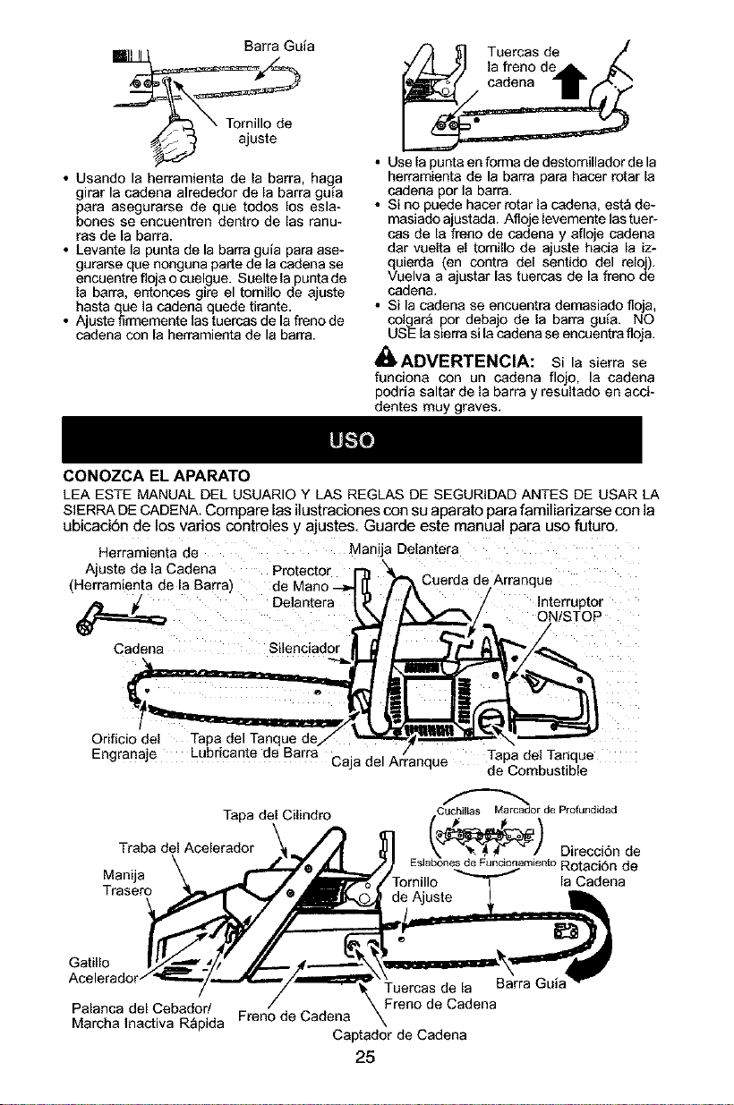
Barra Guia
• Usando la herramienta de la barra, hag a
girar la eadena alrededor de la barra gu_a
para asegurarse de que todos los esla-
bones se encuentren dentm de las ranu-
ras de la barra.
• Levante la punta de la barra guia para ase-
gurarse que nonguna parte de la cadena se
encuentre floja o cuelgue. Suelte la punta de
la barra, entonces gire el tornillo de ajuste
hasta que la cadena quede tirante.
• Ajuste firmemente las tuercas de la freno de
cadena con la herramienta de la barra.
CONOZCA EL APARATO
Tuercas de
la freno de
cadena
• Use la punta en forma de destomillador de la
herramienta de la barra para hacer rotar la
cadena por ]a barra.
• Si no puede hacer rotar la cadena, esta de-
masiado ajustada. Afloje levemente las tuer-
cas de la freno de cadena y afloje cadena
dar vuelta el tomillo de ajuste hacia la iz-
quierda (en contra del sentido del reloj).
Vuelva a ajustar las tuercas de la freno de
cadena.
• Si la cadena se encuentra demasiado floja,
colgar& por debajo de la barra guia. NO
USE la sierra si la cadena se encuentra floja.
_ADVERTENCIA: Si la sierra se
funciona con un cadena flojo, la cadena
podria saltar de la barra y resultado en acci-
dentes muy graves.
LEA ESTE MANUAL DEL USUARIOY LAS REGLASDE SEGURIDADANTES DE USAR LA
SIERRADE CADENA.Compare las ilustraciones con su aparato para familiarizarse con la
ubicaci6n de los varios controles y ajustes. Guarde este manual para uso futuro.
Herramienta de Mar .a Delantera
Ajuste de la Cadena Projector [-j_ "_
(Herramienta de la Barra) de Mano _ II ,f
Delanteralr _ f
Cadena Silenciad
Oriflcio de Tapa del Tanque de/
Lubricante de Barra
Cuerda de Arranaue
_. __ / Interruptor
_/- ON/STOP
Tapa del Tanque
Engranaje Caja del Arranque de Combustible
Tapa del Cilindro
Traba del Acelerador
Manija
Trasero
Cuchilias Marcador de Profundidad
E,ab_o_e)nto Direcci6n de
s o es_ Rotaci6n de
I-ornillo la Cadena
Gatillo
Barra Guia
Palanca del Cebador/ Freno de Cadena
Marcha Inactiva Rapida Freno de Cadena
Captador de Cadena
25

EN/TOPE INTERRUPTOR
El EN/TOPE (ON/STOP) INTERRUPTOR
est_ utilizado para detener la maquina.
GATILLO DE ACELERADOR
El GATILLO DE ACELERADOR controla
velocidad de m_quina.
TRABA DEL ACELERADOR
Es necasario apretar pdmero la TRABA DEL
ACELERADOR para poder accionar el aceler-
ador. Este dispositivo previene el acalerador.
PALANCA DEL CEBADOR/MAR-
GIlA INACTIVA RAPIDA
Las velocidades del acalerador y de la mar-
cha lenta acelerada se fifan accionando la
PALANCA DEL CEBADOR/MARCHA ]N-
ACTIVA R,&,PIDA completamente para mo-
tores frios o para despues del aastecimiento
de combustible. El cabador proporciona
combustible adicional cuando se trata de
poner en marcha un motor frio.
FRENO DE CADENA
El FRENO DE CADENA est_ diseSado para
detener la cadena en caso de reculada. El
freno de cadena se activa automaticamente
en caso de reculadas. El freno de cadena se
activa manualmente si empujan al protector
de mano delantero adelante. Para desacti-
vat el freno de cadena, tire Io m_s posible del
protector de mano delantero hacia la manija
delantera.
TENSION DE LA CADENA
Es normal que las cadenas nuevas se esti-
ren durante los primeros 30 minutos de uso.
Debera verificarse la TENSION DE LA CA-
DENA en la secci6n de MONTAJE.
,i_ ADVERTENCIA: El silenciador es
extremadamente caliente durante el uso y
despu_s de usar el aparato. No toque el si-
lenciador ni permita que el material combus-
tible tal como gasolina o hierba seca hagan
contacto.
_ ADVERTENCIA: Remueva la
tapa del tanque de combustible lentamente
al reabastecer combustible.
ABASTECIMIENTO DEL MOTOR
Este motor est_ habilitado para funcionar con
gasolina sin plomo. Antes de comenzar con el
uso, se deber& mezclar la gasolina con un
aceite de sint6tico de buena calidad para
motores de 2 tiempos enfriados a aire.
Recomendamos el aceite de sint_tico de la
marca Poulan/Weed Eater. Mezcle la gasolina
con el acaite en ]a proporci6n 40:1. Se obtiene
una proporcion de 40:1 mezclando 3.2 onzas
de acaite con cada gal6n de gasolina sin
plomo. Se incluye con esta sierra un recipiente
de 3,2 onzas de acaite. Adiera el contenido
entero de este recipiente en 1 gal6n de
gasolina para alcanzar le mezcla apropiada del
combustible. NO USE acaite para autom6viles
ni para barcas. Estos acaites dafiar&n el motor.
AI mezclar el combustible, siga las
instrucciones impresas en el recipiente. Una
vez haya afiadido el acaite a ]a gasolina, agite
al recipiente brevemente para asegurar que el
combustible est6 completamente mezclado.
Siempre lea y siga las instrucciones de
seguridad que tienen que vet con el
combustible antes de abastecar el aparato.
LUBRICAClON DE LA BARRA Y DE
LA CADENA
La barra y la cadena reqeieren lubricaci6n
constante. El sistema autom_tico de lubrica-
cion provee la lubricacion necasaria mientras
se mantenga Ileno el tanque de acaite. La falta
de acaite arruinar& la barra y la cadena r_pida-
mente. El uso de demasiado poco aciete cau-
sar& excaso de calentamiento que ser& detect-
able pot el humo proveniente de la cadena y/o
per la descctoraci6n de la barra.
Cuando la temperaturea es inferior a O
grados centrigrados, el acaite se pone m_s
grueso, tomando necesaria la adici6n de
una pequeSa cantidad (de 5 a 10%) de Fuel
Oil #1 (#1 Diesel Fuel) oquerosen para diluir
el aceite de la barra y la cadena. El aceite
para barra y cadena fluir libremente para que
el sistema de lubricaci6n pueda bombear
suficiente aceite para lubricar
adecuadamente.
Se recomienda el aceite Poulan o Poulan
Pro® genuino para barra y cadena para
proteger el aparato contra el desgaste
excasivo provocado por el calory la fricci6n.
El aceite Poulan o Poulan PRO® resiste la
p6rdida de espesura a altas temperaturas.
Si no nay disponibilidad de aceite para barra
y cadena Poulan o Poulan PRO® use un
aceite de buena calidad tipo SAE 30.
• Nunca utilice acaite usado para la lubrica-
ci6n de ]a barra y de la cadena.
• Pare siempre el motor antes de abrir la tapa
del tanque de aceite.
IMPORTANTE
La experiencia india que los combustibles
mezclados con alcohol (los Ilamados gasohol
o los que contienen etanol o los que contienen
etanol o metanol) pueden atraer humedad, Io
que puede caesar la separacion y la formaci6n
de &cidos durante el almacenamiento. La ga-
solina acidica puede dafiar el sistema de com-
bustible del motor durante el almacenamiento.
Para evitar problemas con el motor, deber_ va-
ciarse el sistema de combustible antes de ala-
macanar el aparato pot 30 dlas o mas. Vacie
el tanque de combustible, ponga el motor en
marcha y d6jelo en marcha hasta que las
lineas de combustible y el carburador queden
vacios. Cuando vaya a usar el aparato nueva-
mente, use combustible fresco. Vea la seccion
de ALAMACENAJE para mas informaciones.
26
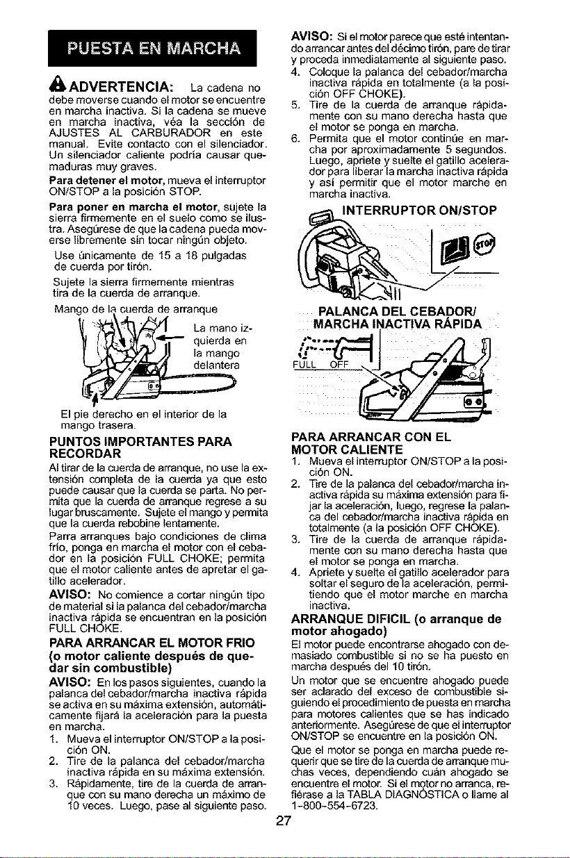
_, ADVERTENCIA:
La cadena no
debe moverse cuando el motor se encuentre
en marcha inactiva. Si la cadena se mueve
en marcha inactiva, v_a la secciOn de
AJUSTES AL CARBURADOR en este
manual. Evite contacto con el silenciador.
Un silenciador caliente podria causar que-
maduras muy graves.
Para detener el motor, mueva el interruptor
ON/STOP a la posiciOn STOP.
Para porter en marcha el motor, sujete la
sierra firmemente en el suelo como se ilus-
tra. AsegL_rese de que la cadena pueda mov-
erse libremente sin tocar ningL_nobjeto.
Use L_nicamente de 15 a 18 pulgadas
de cuerda pot tirOn.
Sujete la sierra firmemente mientras
tira de la cuerda de arranque.
Mango de la cuerda de arranque
• ' '_ La manoiz-
t' _-_ll'l_ - quierda en
f t_,4'_/IJ la mango
El pie derecho en el interior de la
mango trasera.
PUNTOS IMPORTANTES PARA
RECORDAR
AI tirar de la cuerda de arranque, no use la ex-
tension completa de la cuerda ya que esto
puede causar que la cuerda se parta. No per-
mita que la cuerda de arranque regrese a su
lugar bruscamente. Sujete el mango y permita
que la cuerda rebobine lentamente.
Parra arranques bajo condiciones de elima
frio, ponga en marcha el motor con el ceba-
dot en la posicion FULL CHOKE; permita
que el motor caliente antes de apretar el ga-
tillo acelerador.
AVlSO: No comience a cortar ning_n tipo
de material si la palanca del cebador/marcha
inactiva rapida se encuentran en la posiciOn
FULL CHOKE.
PARA ARRANCAR EL MOTOR FRIO
d motor caliente despuds de que-
ar sin combustible)
AVISO: Enlospasossiguientes, cuandola
palanca del cebador/marcha inactiva rapida
se activa en su m_xima extension, autom_ti-
camente fijar_ la aceleracion para la puesta
en marcha.
1. Mueva el interruptor ON/STOP a la posi-
cion ON.
2. Tire de la palanca del cebadodmarcha
inactiva r_pida en su maxima extension.
3. Rapidamente, tire de la cuerda de arran-
que con su mano derecha un m_ximo de
10 veces. Luego, pase al siguiente paso.
AVISO: Si el motor parece que est_ intentan-
do arrancar antes del dOcimo tirOn, pare de tirar
y procada inmediatamente al siguiente paso.
4. Coloque la palanca del cebadodmarcha
inactiva rapida en totalmente (a la posi-
ciOn OFF CHOKE).
5. Tire de la cuerda de arranque rapida-
mente con su mano derecha hasta que
el motor se ponga en marcha.
6. Permita que el motor contim_e en mar-
cha por aproximadamente 5 segundos.
Luego, apdete y suelte el gatillo acelera-
dot para liberar la marcha inactiva r_pida
y asi permitir que el motor marche en
marcha inactiva.
INTERRUPTOR ON/STOP
MARCHA li
PALANCA DEL CEBADOR/
iACTIVA RAPIDA
PARA ARRANCAR CON EL
MOTOR CALIENTE
1. Mueva el interruptor ON/STOP a la posi-
ciOn ON.
2. Tire de la palanca del cebadodmarcha in-
activa rapida su maxima extension para fi-
jar la acaleraciOn, luego, regrese la palan-
ca del cabadodmarcha inactiva rapida en
totalmente (a la posiciOn OFF CHOKE).
3. Tire de la cuerda de arranque rapida-
mente con su mano derecha hasta que
el motor se ponga en marcha.
4. Apriete y suelte el gatillo acelerador para
soltar el seguro de la aceleraciOn, permi-
tiendo que el motor marche en marcha
inactiva.
ARRANQUE DIFICIL (o arranque de
motor ahogado)
El motor puede encontrarse ahogado con de-
masiado combustible si no se ha puesto en
marcha despe_s de110 tirOn.
Un motor que se encuentre ahogado puede
ser aclarado del exceso de combustible si-
guiendo el procedimiento de puesta en marcha
para motores calientes que se has indicado
anteriormente. Aseg_rese de que el interruptor
ON/STOP se encuentre en la posiciOn ON.
Que el motor se ponga en marcha puede re-
querir que se tire de la cuerda de arranque mu-
chas vecas, dependiendo cu&n ahogado se
encuentre el motor. Si el motor no arranca, re-
fi_rase a la TABLA DIAGNOSTICA o Ilame al
1-800-554-6723.
27
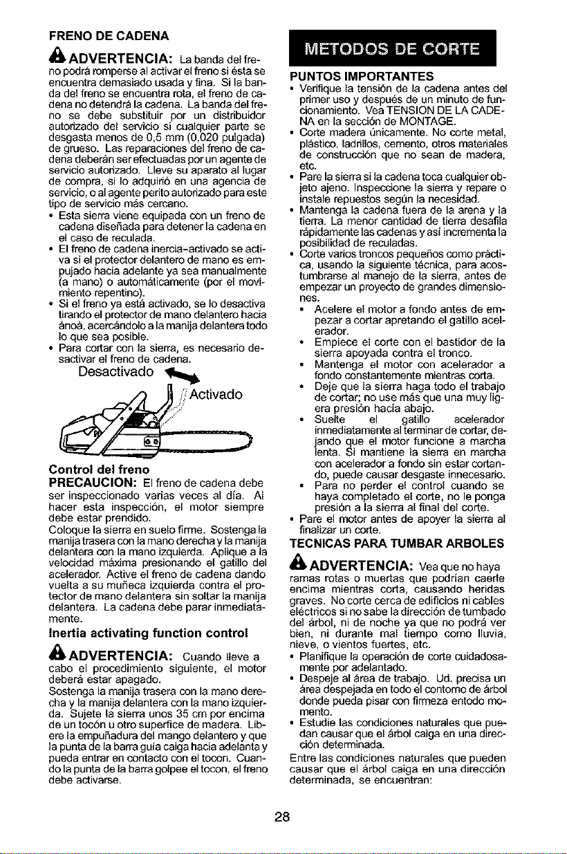
FRENO DE CADENA
ADVERTENClA: La banda del fre-
no podra romperse el activar el freno si _sta se
encuentra demasiado usada y fina. Si la ban-
da del freno se encuentra rot& el freno de ca-
dena no detendr_ la cadena. La banda del fre-
no se debe substituir pot un distribuidor
autodzado del servicio si cualquier parte se
desgasta menos de 0,5 mm (0,020 pulgada)
de grueso. Las reparaciones del freno de ca-
dena deberan ser efectuadas pot un agente de
servicio autorizado. Lleve su aparato el lugar
de compra, si Io adquirio en una agencia de
servicio, o al agente perito autodzado para este
tipo de servicio mas cercano.
• Esta sierra viene equipada con un freno de
cadena diseOada pare detener la cadena en
el caso de reculada.
• El freno de cadena inercia-activado se acti-
va si el protector delantero de mano es em-
pujado hacia adelante ya sea manualmente
(a mano) o aL_om&ticamente (pot el movi-
miento repenfino).
• Si el freno ya est_ activado, se Io desactiva
tirando el protector de mano delantero hacia
Qno& acerc_ndolo ala manija delantera todo
Io que sea posible.
• Pare cortar con la sierra, es necesado de-
sactivar el freno de cadena.
Desactivado
_,_7/i_ Activado
Control del freno
PRECAUCION: El freno de cadena debe
ser inspeccionado varies veces al dfa. AI
hacer esta inspeccion, el motor siempre
debe estar prendido.
Coloque la sierra en suelo firme. Sostenga la
manija trasera con la mano derecha y la manija
delantera con la mano izquierda. Aplique ala
velocidad m&xima presionando el gatil[o de]
acelerador. Active el freno de cadena dando
vaelta a sa muOeca izqaierda contra el pro-
tector de mano delantera sin soitar la manija
delantera. La cadena debe parar inmediata-
mente.
Inertia activating function control
41_ADVERTENCIA: Cuando lleve a
cabo el procedimiento siguiente, el motor
debera estar apagado.
Sostenga la manija trasera con la mano dere-
cha y la manija delantera con la mano izquier-
da. Sujete la sierra unos 35 cm por encima
de un tocOn u otto superfice de madera. Lib-
ere la empuOadura del mango delantero y qee
la panta de la barra gala caiga hacia adelanta y
pueda entrar en contacto con el tocon. Cuan-
do la punta de labarra golpee el tocon, el freno
debe activarse.
PUNTOSIMPORTANTES
• Verifique la tension de la cadena antes del
primer uso y despuOs de un minuto de fun-
cionamiento. Vea TENSION DE LA CADE-
NA en la secci0n de MONTAGE.
• Corte madera _nicamente. No corte metal,
pl_sfico, ladrillos, cemento, otros materiales
de construcciOn que no sean de madera,
etc.
• Pare la sierra si la cadena toca cualquier ob-
jeto ajeno. Inspeccione la sierra y repare o
instale repuestos segt_n la necesidad.
• Mantenga la cadena fuera de la arena y la
tierra. La menor canfidad de tierra desafila
r_pidamente las cadenas y asi incrementa la
posibilidad de reculadas.
• Corte varies troncos pequeffos como practi-
ca, usando la siguiente tOcnica, para acos-
tumbrarse el manejo de la sierra, antes de
empezar un proyecto de grandes dimensio-
lies.
• Acelere el motor a fondo antes de em-
pezar a cortar apretando el gatil]o acel-
erador.
• Empiece el corte con el basfidor de la
sierra apoyada contra el tronco.
• Mantenga el motor con acelerador a
rondo constantemente mientras corta.
• Deje que la sierra haga todo el trabajo
de cortar; no use masque una muy lig-
era presion hacia abajo.
• Suelte el gafillo acelerador
inmediatamente el terminar de cortar, de-
jando que el motor funcione a marcha
lenta. Si mantiene la sierra en marcha
con acelerador a fondo sin estar cortan-
do, puede causar desgaste innecesario.
• Para no perder el control cuando se
haya completado el corte, no le ponga
presiOn ala sierra al final del corte.
• Pare el motor antes de apoyer la sierra al
finalizar un corte.
TECNICAS PARA TUMBAR ARBOLES
ADVERTENCIA: Vea que no haya
ramas rotas o muertas que podrian caerle
encima mientras coda, causando heridas
graves. No corte cerca de edificios ni cables
elOctricos si no sabe la direccion de tumbado
del &rbol, ni de noche ya que no podr_ ver
bien, ni durante mal fiempo como Iluvia,
nieve, o vientos fuertes, etc.
• Planifique la operaciOn de corte cuidadosa-
mente por adelantado.
• Despeje al area de trabajo. Ud. precisa un
area despejada en todo el contomo de arbol
donde pueda pisar con firmeza entodo mo-
mento.
• Estudie las condiciones naturales que pue-
dan causar que el _rbol caiga en una direc-
ci0n determinada.
Entre las condiciones naturales que pueden
causar que el arbol caiga en una direcoiOn
determinada, se encuentran:
28
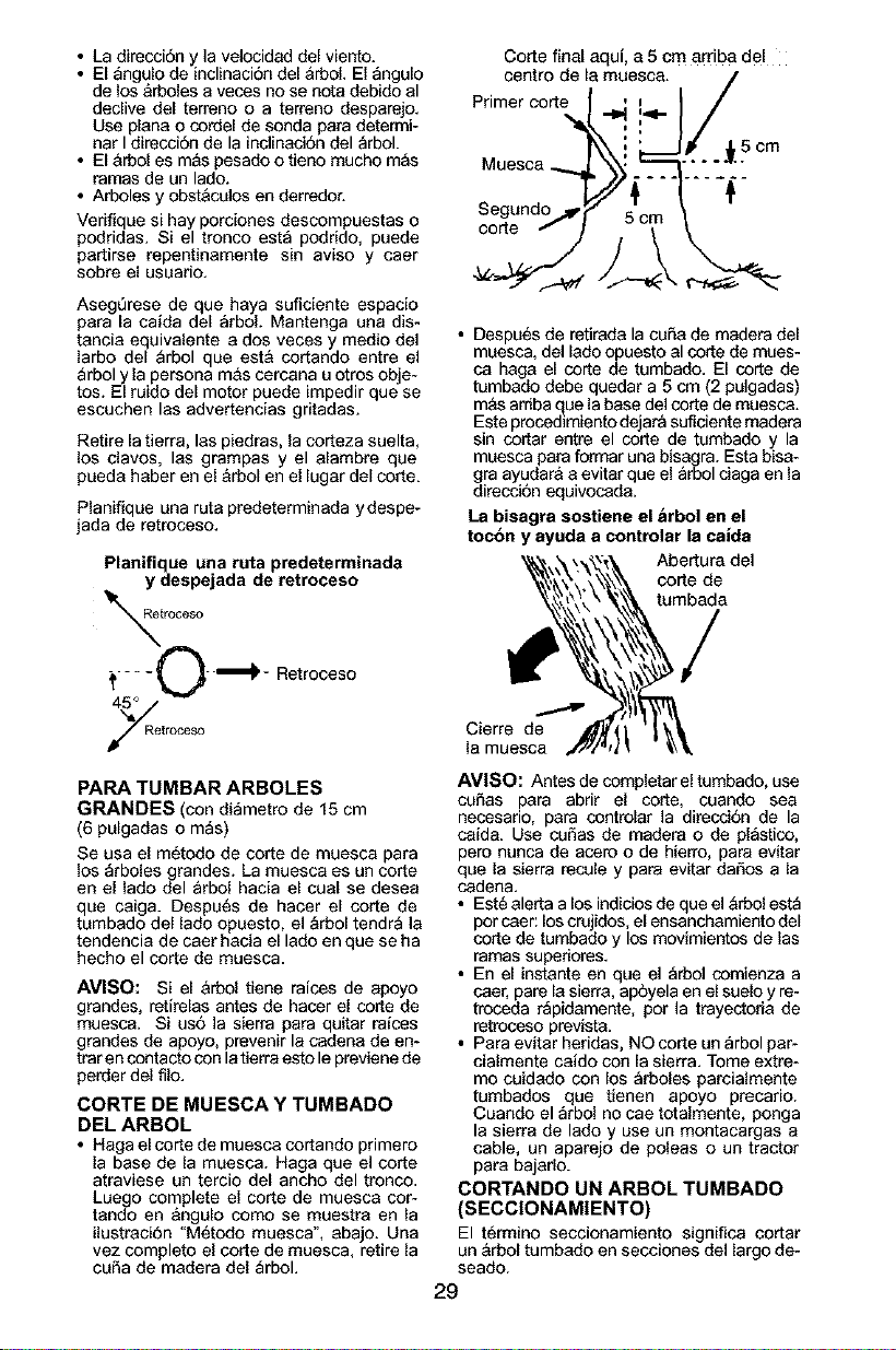
• La direcci6n y la velocidad del viento.
• El _ngulo de inclinaci6n del &rboL El angulo
de los arboles a veces no se nota debido al
declive del terreno o a terreno desparejo.
Use plana o cordel de sonda para determi-
nar Idirecci6n de la inclinaci6n del arbol.
• El &rbol es m&s pesado o tieno mucho m_s
ramas de un lado.
• Arboles y obst&colos en derredor.
Verifique si hay porciones descompuestas o
podridas. Si el tronco est_ podrido, puede
partirse repentinamente sin aviso y caer
sobre el usuario.
AsegOrese de que haya suficiente espacio
para la caida del _rbol. Mantenga una dis-
tancia equivalente a dos veces y medio del
larbo del _rbol que est& cortando entre el
_rbol y la persona m&s cercana u otros obje-
tos. El ruido del motor puede impedir que se
escuchen las advertencias gritadas.
Retire la tierra, las piedras, la corteza suelta,
los clavos, las grampas y el alambre que
pueda haber en el &rbol en el lugar del corte.
Planifique una ruta predeterminada ydespe-
jada de retroceso.
Planifique una ruta predeterminada
y despejada de retroceso
troceso
_.... £)''_ - Retroceso
troeeso
PARA TUMBAR ARBOLES
GRANDES (con di_metro de 15 cm
(6 pulgadas o m_s)
Se usa el m6todo de corte de muesca para
los arboles grandes. La muesca es un corte
en el lado del arbol hacia el cual se desea
que caiga. Despu6s de hacer el corte de
tumbado del lado opuesto, el _rbol tendr_ la
tendencia de caer hacia el lado en que se ha
hecho el corte de muesca.
AVISO: Si el &rbol tiene raices de apoyo
grandes, retirelas antes de hacer el code de
muesca. Si us6 la sierra para quitar raices
grandes de apoyo, prevenir la cadena de en-
trar en contacto con latierra esto le previene de
perder del filo.
CORTE DE MUESCA Y TUMBADO
DEL ARBOL
• Haga elcorte de muesca cortando primero
la base de la muesca. Haga que el corte
atraviese un tercio del ancho del tronco.
Luego complete el corte de muesca cor-
tando en angulo como se muestra en la
ilustraci6n "M6todo muesca", abajo. Una
vez completo el corte de muesca, retire la
cuSa de madera del _rbol.
Corte final aqui, a 5 cm arriba del
centro de la muesca. /
Primer corte r.4=.,_/
"_-:'. i/
k\', ,Scm
Uuesoa _ X,j3 _'-'_."_:''_'_
• Despu6s de retirada la cuSa de madera del
muesca, del lado opuesto al corte de roues-
ca haga el corte de tumbado. El corte de
tumbado debe quedar a 5 cm (2 pulgadas)
m&s arriba que la base del corte de muesca.
Este procedimiento dejar_ suficiente madera
sin cortar entre el corte de tumbado y la
muesca para formar una bisagra. Esta bisa-
gra ayudar& a evitar que el _rbol ciaga en la
direcci6n equivocada.
La bisagra sostiene el &rbol en el
toc6n y ayuda a controlar la calda
Abertura del
corte de
tumbada
Cierre de
la muesca
AV|SO: Antes de completar el tumbado, use
coSas para abrir el corte, cuando sea
necasario, para controlar la direcci6n de la
caida. Use cuSas de madera o de pl_stico,
pero nunca de acero o de hierro, para evitar
que la sierra recule y para evitar daSos a la
cadena.
• Est6 alerta a los indicios de que el _rbol est_
por caer: los crujidos, el ensanchamiento del
corte de tumbado y los movimientos de las
ramas superiores.
• En el instante en que el _rbol comienza a
caer, pare la sierra, ap6yela en el suelo y re-
troceda r_pidamente, pot la trayectoda de
retroceso prevista.
• Para evitar heridas, NOcorte un _rbol par-
cialmente caido con la sierra. Tome extre-
mo cuidado con los _rboles parcialmente
tumbados que tienen apoyo precario.
Cuando el arbol no cae totalmente, ponga
la sierra de lado y use un montacargas a
cable, un aparejo de poleas o un tractor
para bajarlo.
CORTANDO UN ARBOL TUMBADO
(SECCIONAMIENTO)
El t6rmino seccionamiento significa cortar
un &rbol tumbado en secciones del largo de-
seado.
29
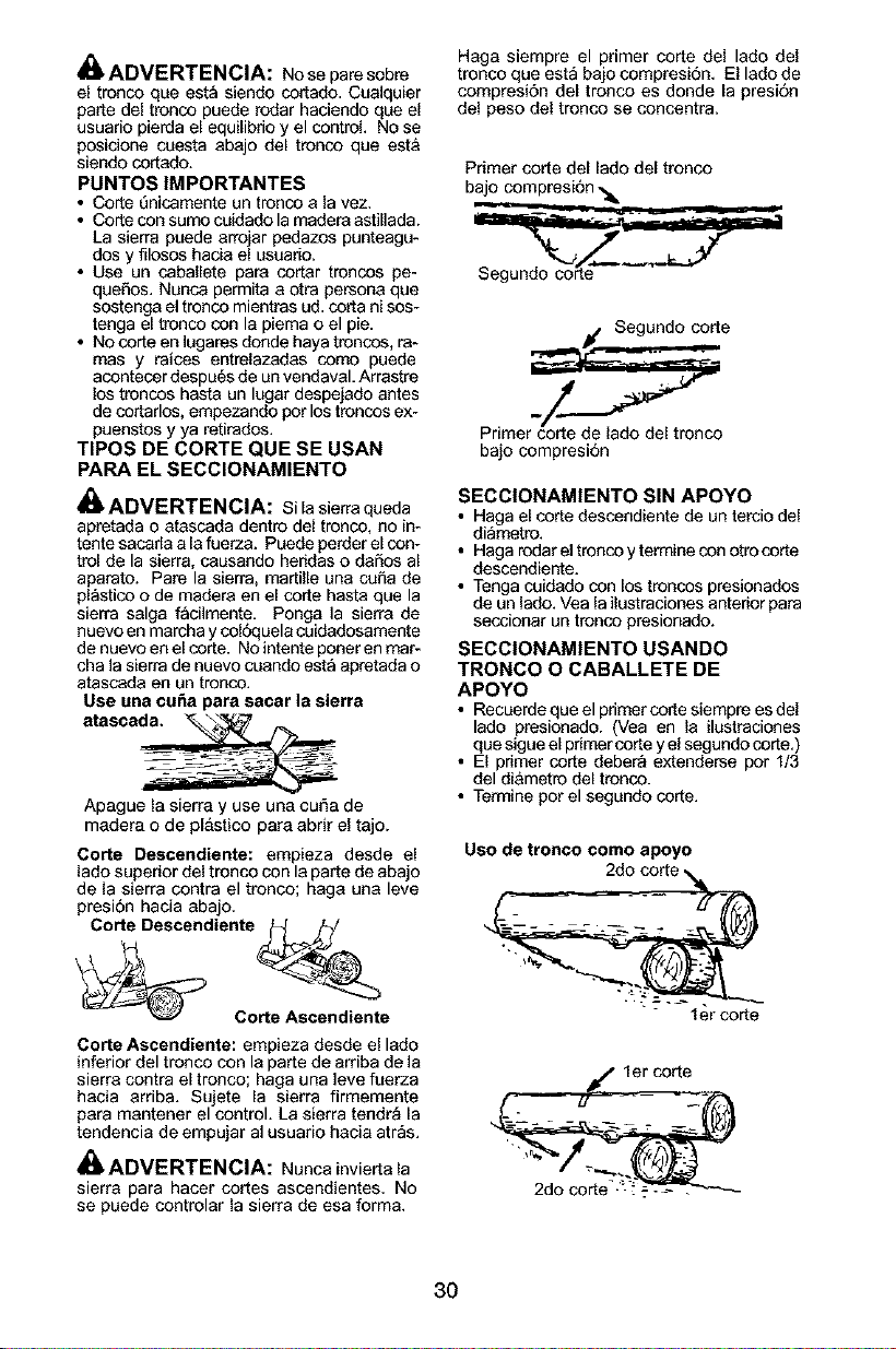
_ ADVERTENCIA: Noseparesobre
el trenco que est_ siendo cortado. Cuaiquier
parte del trenco puede redar haciendo que el
usuario pierda el equilibdo y el control. No se
posicione coesta abajo del trenco que esta
siendo cortado.
PUNTOS IMPORTANTES
• Corte 5nicamente un trenco a la vez,
• Corte con sumo coidado la madera astillada.
La sierra puede arrojar pedazos punteagu-
dos y filosos hacia el usuario.
• Use un caballete para cortar trencos pe-
queSos, Nunca permita aotra persona que
sostenga el trenco mientras ud. corta nisos-
tenga el trenco con la piema o el pie.
• No corte en lugares donde haya trencos, ra-
mas y raices entrelazadas como puede
acontecer despu6s de un vendaval. Arrastre
los troncos hasta un lugar despejado antes
de cortarlos, empezando per los trencos ex-
puenstos y ya retirados.
TIPOS DE CORTE QUE SE USAN
PARA EL SECClONAMIENTO
_ ADVERTENCIA: silasierraqueda
apretada o atascada dentre del trenco, no in-
tente sacada a la fuerza. Puede perder el con-
trol de la sierra, causando heridas o daSos al
aparato. Pare la sierra, martille una cofLa de
plastico o de madera en el corte hasta que la
sierra salga facilmente. Ponga la sierra de
nuevo en marcha y coldquela cuidadosamente
de nuevo en el corte. No intente poner en mar-
cha la sierra de nuevo cuando est_ apretada o
atascada en un trenco.
Use una cufm para sacar la sierra
atasca_
Apague la sierra y use una cuba de
madera o de pl&stico para abrir el tajo.
Corte Descendiente: empieza desde el
lado superior del tronco con la parte de abajo
de la sierra contra el tronco; haga una leve
presion hacia abajo.
Corte Descendiente _/
_ C_e
Corte Ascendiente: empieza desde el lado
inferior del tronco con la parte de arriba de la
sierra contra el tronco; haga una ]eve fuerza
hacia arriba. Sujete la sierra firmemente
para mantener el control. La sierra tendr_ la
tendencia de empujar al usuario hacia atr_s.
_ADVERTENCIA: Nunca invierta la
sierra para hacer cortes ascendientes. No
se puede controlar la sierra de esa form&
Haga siempre el primer corte del lado del
tronco que est_ bajo compresi6n. El lado de
compresi6n del trenco es donde la presi6n
del peso del tronco se concentra.
Primer corte del lado del tronco
bajo compresi6n ._.
if Segundo corte
Primer corte de lado del tronco
bajo compresi6n
SECCIONAMIENTO SIN APOYO
• Haga el corte descendiente de un tercio del
di_metre.
• Haga redar el trenco y termine con otro corte
descendiente.
• Tenga cuidado con los troncos presionados
de un lado. Vea la ilustraciones anterior para
seccionar un trenco presionado.
SECClONAMIENTO USANDO
TRONCO O CABALLETE DE
APOYO
• Recuerde que el primer corte siempre es del
lado presionado. (Vea en la ilustraciones
que sigue el primer corte y el segundo corte.)
• El primer corte debera extenderse por 1/3
del di&metre del tronco.
• Termine por el segundo corte.
Uso de tronco como apoyo
Ier corte
jc/ler corte
- ....
30
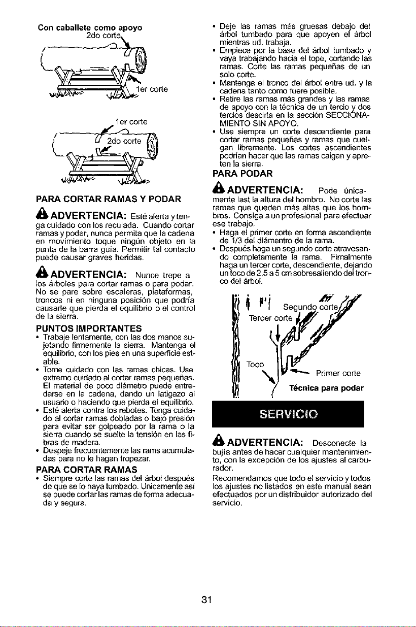
Con caballete como apoyo
/
lerco_e
1er corte
PARA CORTAR RAMAS Y PODAR
ADVERTENClA: Est_ alerta yten-
ga cuidado con Josreeulada. Cuando eortar
ramas y podar, nunca permits que [acadena
en movimiento toque ningun objeto en la
punts de la barra gula. Permitir tal contacto
puede causar graves heridas.
_ADVERTENClA: Nunce trepe a
los &rboles pars cortar ramas o pars podar.
No se pare sobre escaleras, piataformas,
troncos ni en ninguna posici6n que poqria
causarie que pierda el equilibrio o el control
de la sierra.
PUNTOS IMPORTANTES
• Trabaje lentamente, con las dos manos su-
jetando firmemente la sierra. Mantenga el
eqeilibrio, con los pies en una superticie est-
able.
• Tome cuidado con las ramas chicas+ Use
extremo coidado al cor[ar ramas pequeSas.
El material de poco diametro puede entre-
darse en la cadena, dando un latigazo al
usuario o hadendo que pierda el equilibrio+
• Est6 alerts contra los rebotes. Tenga cuida-
do al cortar ramas dobladas o bajo presiSn
pars evitar ser golpeado per la rams o la
sierra cuando se suelte la tensiSn en las fi-
bras de readers+
• Despeje frecoentemente las rams acumula+
das pars no le hagan tropezar.
PARA CORTAR RAMAS
• Siempre corte las ramas del _rbol despu_s
de que se Io hays tumbado. Unicamente as{
se puede cortar las ramas de forms adecua-
day segura+
• Deje las ramas m_s gruesas debajo deJ
&rbo{ tumbado pars que apoyen el _rbol
mientras ud. trabaja.
• Empiece por [a base de[ arbol tumbado y
vaya trabajando hacia el tope, cortando las
ramas+ Corte las ramas pequefias de un
solo corte.
• Mantenga el tronco del &rbol entre ud. y [a
cadena tanto come fuere posible.
• Retire las ramas mas grandes y las ramas
de apoyo con la t@cnica de un terdo y dos
tercios descirta en la secci6n SECCIONA-
MIENTO SIN APOYO.
• Use siempre un corte descendiente pars
cortar ramas pequeSas y ramas que cuei-
gan libremente. Los cores ascendientes
podfian hacer que las ramas caigan y apre-
ten la sierra.
PARA PODAR
i_ ADVERTENCIA: Pede t_nica-
mente last la altura del hombro. No corte las
ramas que queden mas altas que los horn-
bros. Consiga a un profesional pars efectuar
ese trabajo.
• Hags el primer corte en forms ascendiente
de 1/3 del diamentro de [a rams.
• Despu@shags un segundo corte atravesan-
do completamente la rams. Fimalmente
hags un tercer core, descendiente, dejando
un toco de 2,5 a 5cm sobresaliendo deJtron-
co del _rboL
LrJlcJe! Segundo coJY[_/J
Toco
" T_cnica para podar
ADVERTENCIA:
Desconecte la
bujia antes de hacer cualquier mantenimien-
to, con [a excepci6n de los ajustes al carbu-
rador.
Recomendamos que todo el servicio ytoqos
los ajustes no [istados en este manual sean
efectuados por un distribuidor autorizado de]
servic{o+
31
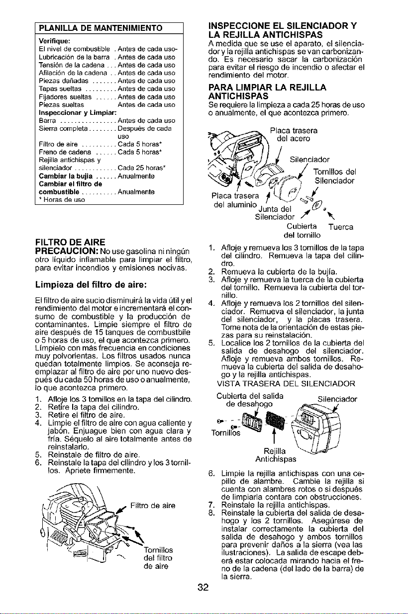
PLANILLA DE MANTENIMIENTO
Verifique:
El nivel de combustible . Antes de cada uso-
Lubricad6n de la barra . Antes de cada uso
TensiSn de la cadena... Antes de cada uso
Afilaci6n de la cadena .. Antes de cada uso
Piezas daSadas ....... Antes de cada uso
Tapas sueltas ......... Antes de cada uso
Fijadores sueltas ...... Antes de cada uso
Piezas suettas Antes de cada uso
Inspeccionar y Limpiar:
Barra ................ Antes de cada uso
Sierra completa ........ Despu_s de cada
USO
Filtro de aire .......... Cada 5 horas*
Freno de cadena ...... Cada 5 horas*
Rejilla antichispas y
silenciador ............ Cada 25 horas*
Cambiar la bujia ...... Anualmente
Cambiar el filtro de
combustible .......... Anualmente
* aoras de uso
FILTRO DE AIRE
PRECAUCION: No use gasolina ni ningQn
otto Ifquido inflamable para limpiar el filtro,
para evitar incendios y emisiones nocivas.
Limpieza del filtro de aire:
El filtro de aire sucio disminuir& la vida Qtily el
rendimiento del motor e incrementar_ el con-
sumo de combustible y la produccion de
contaminantes. Limpie siempre el filtro de
aire despu_s de 15 tanques de combustbile
o 5 horas de uso. el que acontezca primero.
Lfmpielo con m_s frecoencia en condiciones
muy polvorientas. Los filtros usados nunca
quedan totalmente limpios. Se aconseja re-
emplazar al filtro de aire por uno nuevo des-
pues du cada 50 horas de uso o anualmente.
Io que acontezca primero.
1. Afloje los 3 tomillos en la tapa del cilindro.
2. Retire la tapa del cilindro.
3. Retire el filtro de aire.
4. Limpie el filtro de aire con agua caliente y
jabon. Enjuague bien con agua clara y
fria. S_quelo al aire totalmente antes de
reinstalarlo.
5. Reinstale de filtro de aire.
6. Reinstale la tapa del cilindro y los 3tomil-
los. Apriete firmemente.
._._To_,f Filtro de aire
de aire
INSPECCIONE EL SILENCIADOR Y
LA REJILLA ANTICH|SPAS
A medida que se use el aparato, el silencia-
dory la rejilla antichispas se van carbonizan-
do. Es necesario sacar la carbonizaciOn
para evitar el riesgo de incendio o afectar el
rendimiento del motor.
PARA MMPIAR LA REJILLA
ANTICHISPAS
Serequierela limpiezaacada 25 horasdeuso
o anualmente,el que acontezca pdmero.
32
Placa trasera
_' d_lacero,
Silenciador
"./">_J,/_/'_ J Tornillos del
"_l_._/.(_ Silenciador
Plaoatrasera 41_[_F_ _
del aluminiO.u/n _ _ _._
J ta ael
Silenciador /4 _.
Cubierta Tuerca
del tomillo
1. Afloje y remueva los 3 tomillos de la tapa
del cilindro. Remueva la tapa del cilin-
dro.
2. Remueva la cubierta de la bujfa.
3. Afloje y remueva la tuerca de la cubierta
del tornillo. Remueva la cubierta del tor-
nillo.
4. Afloje y remueva los 2 tornillos del silen-
ciador. Remueva el silenciador, la junta
del silenciador, y la placas trasera.
Tome nora de la orientaci6n de estas pie-
zas para su reinstalaci6n.
5. Localice los 2 tomillos de la cubierta del
salida de desahogo del silenciador.
Afloje y remueva ambos tomillos. Re-
mueva la cubierta del salida de desaho-
go y la rejilla antichispas.
VISTA TRASERA DEL SlLENClADOR
Cubierta del salida Silenciador
de desahogo _ ./
Tornil_os
Rejilla
Antichispas
6,
7.
8.
Limpie la rejilla antichispas con una ce-
pillo de alambre. Cambie la rejilla si
cuenta con alambres rotos o si despu_s
de limpiarla contara con obstrucciones.
Reinstale la rejilla antichispas.
Reinstale la cubierta del salida de desa-
hogo y los 2 tornillos. Asegt_rese de
instalar correctamente la cubierta del
salida de desahogo y ambos tomillos
para prevenir da_os a la sierra (vea las
ilustraciones). La salida de escape deb-
er_ estar colocada mirando hacia el fre-
no de la cadena (del lado de la barra) de
la sierra.
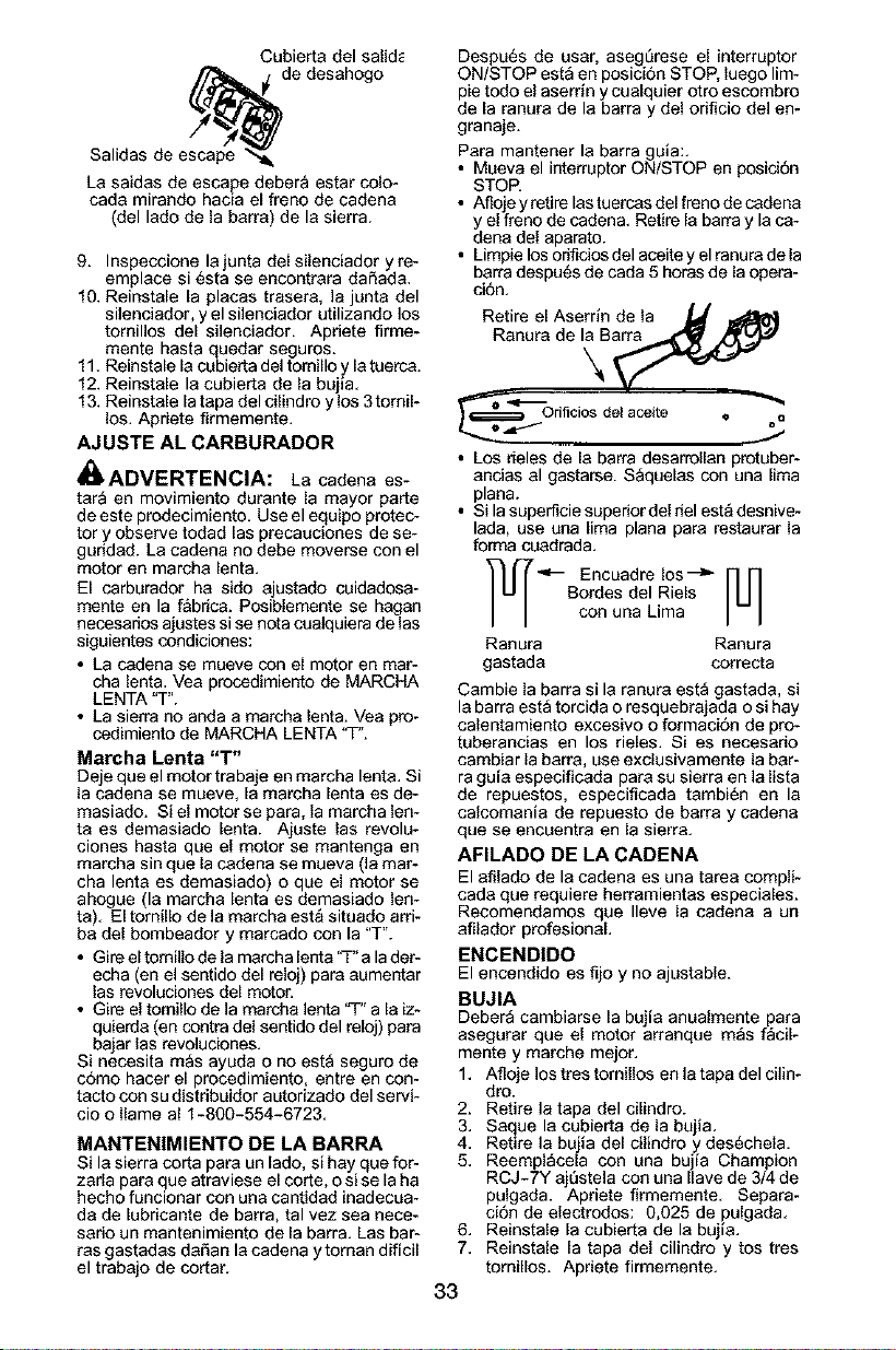
Cubiertadelsalid_
Salidasdee_c.ap_e_e_d
desahogo
Lasaidasdeescapedeberaestarcolo-
cadamirandohaciaelfrenodecadena
(delladodelabarra)delasierra.
9. Inspeccionelajuntadelsilenoiadoryre-
emplacesi6staseencontraradafiada.
10.Reinstalelaplacastrasera,lajuntadel
silenciador,yelsilenciadorutilizandolos
tomillosdelsilenciador.Apdeteflrme-
mentehastaquedarseguros.
11.Reinstalelacubiertadeltomilloylatuerca.
12.Reinstalelacubiertadelabujia.
13.Reinstalelatapadelcilindroylos3tomil-
los.Aprietefirmemente.
AJUSTE AL CARBURADOR
_,ADVERTENClA: La cadena es-
tar_ en movimiento durante la mayor parte
de este prodecimiento. Use el equipo protec-
tor y observe todad las precauciones de se-
guridad. La cadena no debe moverse con el
motor en marcha lenta.
El carburador ha sido ajustado cuidadosa-
mente en la f&brica. Posiblemente se hagan
necesarios ajustes si se nota cualquiera de las
siguientes condiciones:
• La cadena se mueve con el motor en mar-
cha lenta. Vea procedimiento de MARCHA
LENTA "T".
• La sierra no anda a marcha lenta. Vea pro-
cedimiento de MARCHA LENTA "T".
Marcha Lenta "T"
Deje que el motor trabaje en marcha lenta, Si
la cadena se mueve, la marcha lenta es de-
masiado. Si el motor se para, la marcha len-
ta es demasiado lenta. Ajuste las revolu-
ciones hasta que el motor se mantenga en
marcha sin que la cadena se mueva (la mar-
cha lenta es demasiado) o que el motor se
ahogue (la marcha lenta es demasiado len-
ta). El tomillo de la marcha est_ situado arri-
ba del bombeador y marcado con la "T".
• Gire el tomillo de la marcha lenta 'q-"a la der-
echa (en el sentido del reloj) para aumentar
las revoluciones del motor.
• Gire el tornillo de la marc.ha lenta 'q-" a la iz-
quierda (en contra del sentido del reloj) para
bajar las revoluciones.
Si necesita mas ayuda o no esta seguro de
c6mo hacer el procedimiento, entre en con-
tacto con su distribuidor autorizado del servi-
cio o Ilame al 1-800-554-6723.
MANTENIMIENTO DE LA BARRA
Si la sierra corta para un lado, si hay que for-
zarla para que atraviese el corte, o si se la ha
hecho funcionar con una cantidad inadecoa-
da de lubricante de barra, tal vez sea nece-
sario un mantenimiento de la barra. Las bar-
ras gastadas dafian la cadena ytoman dificil
el trabajo de cortar.
Despu6s de usar, aseg_rese el interruptor
ON/STOP esta en posici6n STOP, luego lim-
pie todo el aserrin y cualquier otto escombro
de la ranura de la barra y del orificio del en-
granaje.
Para mantener la barra gala:.
• Mueva el interruptor ON/STOP en posici6n
STOR
• Afloje y retire las tuercas del freno de cadena
y el freno de cadena. Retire la barra y la ca-
dena del aparato.
• Limpie los orificios del aceite y el ranura de la
barra despu6s de cada 5 horas de la opera-
ci6n,
Retire el Aserrin de la _
Ranura de la Barra
°,,_"_}€;;_-- 3rificios del aceite
O
Q
• Los deles de la barra desarrollan protuber-
ancias al gastarse. Saquelas con una lima
plana.
• Si la superficie superior del riel est_ desnive-
lada, use una lima plana para restaurar la
forma cuadrada.
"_-- Encuadre los ---_ [_
Bordes del Riels
con una Lima
Ranura Ranura
gastada correcta
Cambie la barra si la ranura est_ gastada, si
la barra est_ torcida o resquebrajada o si hay
calentamiento excesivo o formaci6n de pro-
tuberanoias en los rieles. Si es necesario
cambiar la barra, use exclusivamente la bar-
ra guia especificada para su sierra en la lista
de repuestos, especificada tambi6n en la
calcomania de repuesto de barra y cadena
que se encuentra en la sierra.
AFILADO DE LA CADENA
El afilado de la cadena es una tarea compli-
cada que requiere herramientas especiales.
Recomendamos que Ileve la cadena a un
afilador profesionaL
ENCEND|DO
El encendido es fijo y no ajustable.
BUJIA
Debera cambiarse la bujia anualmente para
asegurar que el motor arranque m_s f_cil-
mente y marche mejor.
1. Afloje los tres tornillos en la tapa del cilin-
dro.
2. Retire la tapa del cilindro.
3. Saque la cubierta de la bujia.
4. Retire la bujia del cilindro y des6chela.
5. Reempl_cela con una bujia Champion
RCJ-7Y ajSstela con una Ilave de 3/4 de
pulgada. Apriete firmemente. Separa-
ci6n de electrodos: 0,025 de pulgada.
6. Reinstale la cubierta de la bujia.
7. Reinstale la tapa del cilindro y tos tres
tomillos. Apriete firmemente.
33
Cubiertade
labujia
ALMACENAJE
_,ADVERTENCIA: Pare el motor y
deje que se enfrie y fije bien el aparato antes
de guardarlo o de transportado en un
vehiculo. Guarde el aparato y el combustible
en un lugar donde los vapores de combus-
tible no pueden hacer contacto con chispas
ni llamas abiertas provenientes de los termo-
tanques, los motores o interruptores el6ctd-
cos, los calefactores centrales, etc. Guarde
el aparato con todos los protectores en sus
lugares respectivos. Col6quelo de modo
que no pueda haber accidentes a los trans-
et_ntes con objetos fllosos. Guarde el apara-
to fuera del alcance de los niSos.
• Antes de guardar el aparato, vacie todo el
combustilbe. Ponga en marcha el motor y
d6jelo en marcha lenta hasta que el motor
para solo,
• Limpie el aparato antes de guardarlo. Preste
atencion especialmente a] _rea de entrada
de aire, manteni6ndola libre de escombros.
Use un detergente suave y una esponja
para limpiar las superficies de pl_stico.
• No guarde el aparato niel combustible en lu-
gares cerrados donde los vapores de com-
bustible puedan alcanzar chispsas o llamas
abierfas de los termotanques, calefactores
centrales, motores o interruptores el6ctr_cos,
etc.
• Guarde el aparato en un lugar seco fuera del
alcance de los niSos.
PRECAUCION: Es importante prevenir la
formacSn de depositos de goma en las pie-
zas esenciales del sistema de combustible,
tales como el carburador, el filtro de combus-
tible, la manguera de combustible o el tan-
que, durante el aimacenado. Los combus-
tibles con mezcla de alcohol (el Ilamado
gasohol o que use etanol o methanol) pue-
den atraer humedad, que Ileva a la sepa-
rac'on y a la formac'on de'acidos durante el
almacenado. La gasolina acidica puede
daSar el motor.
_,INECESITA AYUDA?
ame al 1-800-554-6723.
&NECESITA REPUESTO?
Entre en contacto con su distribuidor autori-
zado del servicio.
34

TABLA DIAGNOSTICA
_, ADVERTENClA: Siempre apague el aparato y desconecte la bujia antes de hacer
cualquiera de las reparaciones recomendadas a continuaci6n excepto reparaciones
que requieran que [a unidad est_ en operaci6n.
PROBLEMA
El motor no
arranca o se
mantiene en
marcha s61o
unos segundos
despu6s de ar-
rancar,
El motor no
anda en
marcha lenta
como debe.
CAUSA
1. El interruptor esta off.
2. El motor esta ahogado.
3. El tanque de
combustible esta vacio.
4. La bujia no hace chispa.
5. El combustible no est_
Ilegando al carburador.
SOLUCION
1. Coloque el interruptor en ON.
2. Vea "Arranque Dificir' en la
seccion Uso.
3. Llene el tanque con la mezcla
correcta de combustible.
4. Instale una bujia nueva.
5. Verifique si el filtro de combustible
est_ sucio; Ifmpielo. Verifique si hay
dobleces en la linea de combustible
o siesta partida: rep_rla o c_mbiela.
1. Vea "Ajuste al Carburador" en la
secci6n Servicio.
2. Entre en contacto con su distribuidor
autorizado del servicio.
1. La marcha lenta
requiere ajuste.
2. El carburador requiere
ajuste.
1. El filtro de aire esta
sucio.
2. La bujfa esta
carbonizad&
3. La freno de cadena es
activado.
4. El carburador requiere
ajuste.
1. La marcha lenta
requiere ajuste.
2. El embrague requiere
reparaciones.
El motor no 1. Limpie o cambie el filtro de aire.
acelera, le falta
potencia o se 2. Limpie o cambie la bujfa y
para bajo car- calibre la separaci6n.
ga. 3. Desactive el freno de cadena.
4. Entre en contacto con su distribuidor
autorizado del servicio.
El motor 1. La mezcla de combus-
humea tible se ha hecho.
excesivamente.
La cadena se
mueve en
marcha lent&
1. Vacie el tanque de combustible
y 116nelode combustible con la
mezcla correct&
1. Vea "Ajuste al Carburador" en la
secci6n Servicio.
2. Entre en contacto con su distribuidor
autorizado del servicio.
ELECTROLUX HOME PRODUCTS, INC.,
garantiza al comprador original que cada sierra
de cadena a gasolina marca Poulan PRO®
nueva sera Iibre de defectos de materiales y de
mano de obra y que se compromete a reparar
o reemplazar, bajo las condiciones de esta ga-
rantia, toda sierra de cadena a gasolina do-
mestica defectuosa, como se detalla a conti-
nuacion, a partir de la fecha de compra original:
2 AI_IOS - Repuestos y Mano de Obra,
cuando usada para prop6sitos dom_sticos.
60 DIAS - Repuestos y Mano de Obra, si usa-
do para prop6sitos comerciales, profesionales
o para producir ingresos.
30 DIAS - Repuestos y Mano de Obra, si usa-
do para prop6sitos de alquiler.
Esta garantia no es transferible y no cubre
dafios ni responsabilidad civil debidos a man-
ejo indebido, mantenimiento incorrecto ni uso
de accesorios y/o uegos de piezas adicio-
hales no recomendados especificamentepor
ELECTROLUX HOME PRODUCTS, INC.,
para esta sierra de cadena. Asimismo, esta
garantia no cubre daSos causados por manejo
indebido, mantenimiento incorrecto ni tampoco
si la sierra ha sido alterada de cualquier modo
que seg6n nuestro criterio afecte su condici6n
o su operacion. Esta garantfa no cubre afina-
clones, bujias, filtros, sogas de arranque, re-
sortes de arrangque, afilado de cadenas, bar-
ras, cadenas ni otras piezas que se gastan y
requieren reemplazo con el uso razonable du-
rante el perfodo de vigencia de la garantia.
Esta garantfa no cubre la preparacion de pre-
entrega, la instalaci6n de la barra gufa y la ca-
dena y los ajustes normales explicados en el
manual de instrucciones tales como los
ajustes al carburador y a la tensi6n de lacade-
ha. Esta garantia no cubre el costo de flete.
ESTA GARANTIA CONFIERE DERECHOS
JURIDICOS ESPECIFICOS AL COMPRA-
DOR, QUE PUEDE TENER OTROS DERE-
CHOS QUE VARIAN ENTRE ESTADOS.
NO SE ADMITIRAN RECLAMOS POR
DAI_IOS CONSECUENTES NI POR OTROS
DAi_IOS NI SE APLICARA NINGUNA OTRA
GARANTIA EXPRESA ADEMAS DE
AQUELLAS EXPRESAMENTE ESTIPULA-
DAS EN LA PRESENTE.
35

ALGUNOS ESTADOS NO PERMITEN LIMI-
TACIONES DEL PERIODO DE VIGENCIA
DE GARANTIAS IMPLICITAS, NI LA EXCLU-
SION DE DANOS CONSECUENTES O IN-
ClDENTALES, NI SU LIMITACION, DE
MODO QUE LA EXCLUSION Y LAS LIMITA-
CLONES ANTERIORES PUEDEN NO TEN-
ER VALIDEZ EN SU CASO.
Es norma de ELECTROLUX HOME PROD-
UCTS, INC., mejorar sus productos continua-
mente. Pot Io tanto, ELECTROLUX HOME
PRODUCTS, INC., se reserva el derecho de
cambiar, modificar o descontinoar modelos,
diseSos, especificationes y accasorios de to-
dos los productos en cualquier momento sin
previo aviso ni responsabilidad para con
ningQn comprador.
SUS DERECHOS Y OBLIGACIONES DE
GARANTIA: La Agencia de Protecci6n Ambi-
ental de los Estados Unidos, la Agenda Ambi-
enta] Canadiense y ELECTROLUX HOME
PRODUCTS, INC., se complasen en explicar
la garantia con la que cuenta el sistema de
control de emision en su motor peque_o, mo-
delo 2002-2064, para uso faera de carretera.
ELECTROLUX HOME PRODUCTS, INC.,
deber_ garantizar el sistema de control de emi-
sion an su maquina de motor pequeSo para
uso fuera de carretera por los pedodos de
tiempo que explicamos a continuacidn y con la
condici6n de que su m&quina de motor pe-
queSo para uso fuera de carretera no haya su-
frido ningQn tipo de abuso, negligencia o man-
tenimiento inapropiado. Su sistema de control
de emisi6n incluye piezas tales como el carbu-
rador y el sistema de ignici6n. Dnode exista
una condicion qua requiera reparaci6n bajo
garantia, ELECTROLUX HOME PROD-
UCTS, INC., reparar_ gratis su motor pequeSo
para uso fuera de carretera. Los gatos cubier-
tos bajo la garantia incluyen el diagn6stico, las
piezas y labor. CUBIERTA DE GARAN-
TIA DEL FABRIOANTE: Si cualquier pieza re-
lacionada con el sistema de emisi6n de su mo-
tor (como hemos enumerado en la lista de
piezas de control de emision bajo garantia) se
encontrara defectuosa o defectos en el mated-
al o en la labor del motor causaran que tal pie-
za comenzara afallar, la pieza sera reparada o
reemplazada por ELECTROLUX HOME
PRODUCTS, INC. GARANTIA DE RE-
SPONSABILIDAD DE DEL DUENO: Como
dueSo de una maquina de motor pequeSo para
uso fuera de carretera, usted se_ responsable
por el mantenimiento adecuado en los perio-
dos previamente programados y enumerados
en su manual de instrucciones. ELECTRO-
LUX HOME PRODUCTS, INC., recomienda
que guarde todos los recibos que indiquen que
se ha desempeSado mantenimiento en su
m_quina de motor peque_o para uso fuera de
carretera, pero ELECTROLUX HOME PROD-
UCTS, INC., no podr_ negar el servicio bajo
garantia Qnicamente a causa de la falta de re-
cibos o por el incumplimiento de su parte en
asegurarse qua el mantenimiento programado
haya sido desempefLado. Como dueSo de una
m_quina de motor pequefLo para uso fuera de
carretera, usted deber_ contar con el conoci-
miento de que ELECTROLUX HOME PROD-
UCTS, INC., puede negar la cubierta bajo ga-
rantia si su m_quina de motor pequeSo para
uso fuera de carretera o algeria pieza de la
misma ha dejado de funcionar debido aI abuso,
negligencia, mantenimiento inapropiado, mo-
dificaciones no aprobadas o el uso de piezas
que no hayan sido fabdcadas o aprobadas por
el fabric.ante original deI equipo. Es respnosa-
bilidad suya el Ilevar su maquina de motor pe-
queSo para uso fuera de carretera a un centro
de reparaci6n autorizado ELECTROLUX
HOME PRODUCTS, INC., tan pronto como
se presente el problema. Las reparaciones
bajo garant{a deberan ser completadas en un
periodo de tiempo razonable, qua no excada
los 30 d{as. Si cuenta usted con alguna pre-
gunta en relaci6n a sus derechos y responsa-
bilidades de garantia, usted debera comuni-
carse con su distfibuidor a_orizado deI
servicio mas cercano o Ilamar a ELECTRO-
LUX HOME PRODUCTS, INC., al
1-800-554-6723. FEGHA DEL COMIENZA
DE LA GARANTIA: El periodo de garant{a
comienza en lafecha de compra de la m&quina
de motor pequefto para uso fuera de carretera.
DURAClON DE LA GARANTIA: Esta ga-
rantia cuenta con un periodo de duraci6n de
dos aSos comenzando en la fecha inicial de
compra, QUE CUBRE LA GARANTIA: RE-
PARACION O REEMPLAZO DE PIEZAS.
La reparacion o el reemplazo de cualquier pie-
za garantizada ser&n desempeSados y ofred-
dos al dueSo sin costo alguno en un distribui-
dor autorizado del servicio ELECTROLUX
HOME PRODUCTS, INC. Si cuenta usted con
alguna pregunta en relacion a sus derechos y
responsabilidades de garantia, usted debera
comunicarse con su distfibuidor autodzado del
servicio mas cercano o Ilamar a ELECTRO-
LUX HOME PRODUCTS, INC., al
1-800-554-6723. PERIODO DE GARAN-
TIA: Cualquier pieza garantizada que no est6
programada para ser reemplazada comoparte
del mantenimiento requerido, o que estepro-
gramada L_nicamentepara inspecci6n regular
para efectos de "reparaci6n o reemplazo si
fuera necasario" debera garantizarse por un
periodo de dos aSos. Cualquier pieza garanti-
zada que est6 programada para ser reempla-
zada como parte del mantenimiento requeddo
deber_ estar garantizada por el periodo de
tiempo que comienza en la fecha de compra
iniciaI hasta la fecha del primer reemplazo pro-
gramado para dicha pieza. DIAGNOSTICO:
No se debera cobrar al dueSo ningL_ntipo de
cargos por la labor de diagn6stico la cual deter-
mine que una pieza garantizada se encoentra
defectuosa si el trabajo de diagnostico ha sido
desempef_ado por un distdbuidor autorizado
del servicio ELECTROLUX HOME PROD-
UCTS, INC. DANOS POR CONSECUEGIA:
36
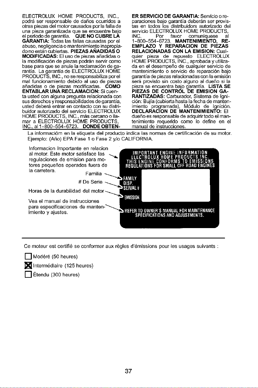
ELECTROLUXHOMEPRODUCTS,iNC.,
podraserresponsablededafiosocurridosa
otraspiezasdelmotorcausadosporlafallade
unapiezagarantizadaqueseencuentrebao
elperiododegarantfa.QUE NO CUBRE LA
GARANTIA: Todas las fallas causadas por el
abuso, negligencia o mantenimieEto inapropia-
do no est&n cubiertas. PIEZAS ANADIDAS O
MODIFICADAS: El uso de piezas afiadidas o
la modificacion de piezas podran servir como
base para que se anule la reclamaci6n de ga-
rantia. La garantfa de ELECTROLUX HOME
PRODUCTS, iNC., no se responsabiliza por el
mal funcionamiento debido al uso de piezas
afiadidas o de piezas modificadas. COMO
ENTABLAR UNA RECLAMAClON: Si cuen-
ta usted con alguna pregunta relacionada con
sus derechos yresponsabilidades de garantia,
usted deber_ entrar en contacto con su distd-
buidor autorizado del servicio ELECTROLUX
HOME PRODUCTS, INC., m_s cercano o Ila-
mar a ELECTROLUX HOME PRODUCTS,
INC., al 1-800-554-6723. DONDE OBTEN-
ER SERVICIO DE GARANTIA: Servicio o re-
paraciones bajo garantia deberan set provis-
tas en todos los distribuidors autorizado del
servicio ELECTROLUX HOME PRODUCTS,
iNC. Pot favor comuniquese al
1-800-554-6723. MANTENIMIENTO, RE-
EMPLAZO Y REPARACION DE PIEZAS
RELACIONADAS CON LA EMISION: Cual-
quier pieza de repuesto ELECTROLUX
HOME PRODUCTS, INC., aprobada y utiliza-
da en el desempefio de cualquier servicio de
mantenimiento o servicio de reparaci6n bajo
garantia de piezas relacionadas con la emisi6n
ser_ provisto sin costo algano al duefio si la
pieza se encuentra bajo garantfa. USTA SE
PIEZAS DE CONTROL DE EMISION GA-
RANTIZADAS: Carburador, Sistema de Igni-
ci6n: Bujfa (cebieda hasta la fecha de manten-
imiento programada), M6dulo de Ignici6n.
DECLARACION DE MANTENIMIENTO: El
dueSo es responsable de adquirir todo elman-
tenimiento requerido como Io define en el
manual de instrucciones.
La informaci6m en la etiqueta del producto indica las normas de certificacion de su motor.
Ejemplo: (Afio) EPA Fase 1 o Fase 2 y/o CALIFORNIA.
Informacion Importante en relacion
al motor. Este motor satisface las
regulaciones de emision para mo-
tores pequefios operados fuera de
la carretera.
# De Serie
Horas de la durabilidad
Yea el manual de instrucciones
para especificaciones
imiento y ajustes.
Ce moteur est certifi6 se conformer aux regles d'_rnissions pour les usages suivants :
[] Mod6r_ (50 heures)
[]lnterm6diaire (125 heures)
[] €:tendu (300 heures)
37