Mouli Engineering Inc. © 2014; U.S. Patent No. 8,716,889 Rev. 8 May 23, 2014
SolarPod
◌TM
Grid Tied Installation sequence
There will be one package (or palette) of materials. This palette contains six sections (A1, A2,
A3, A4, B1 & B2). A1, A2, A3, A4 are top panel portion and B1 and B2 are bottom portions.
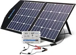
1. We will connect the B1 and B2 using the leg brackets. Secure the bolts and tighten. Splice bar
shown is not necessary for most applications and is placed only in hurricane prone regions. The
closeup of the splice is shown below. If you require splice bars for your application please call
SolarPod
TM
.
2. Then the six feet’s will be attached to the bottom portion (B1 and B2) as shown below and tighten.
3. The ground is prepared using six patio
blocks and leveled.
4. The SolarPod
TM
bottom frame is placed
on the patio blocks. The Easy hook
anchors are driven into the four corner
leg plates anchoring them securely. Use
additional ways to secure the leg to the
ground or roof if you feel it is necessary.
5. Join A1 and A2 using the plate (“T”) joint
provided. A1 can be identified easily
since it is the only solar panel with cable
that has been coiled and tied to the
frame.
6. Join A3 and A4 using the plate (“T”) joint
provided.
Mouli Engineering Inc. © 2014; U.S. Patent No. 8,716,889 Rev. 8 May 23, 2014
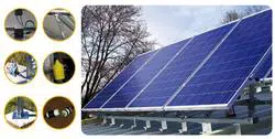
7. A1 & A2 will then be attached to the B1 side of the bottom portion through the hinge nut. Closeup
of the hinge is given below. Tighten the hinge. (A1&A2 is the panel top half with coil of wire)
8. The A3 & A4 will then be attached to the B2 side of the bottom portion through the hinge nut.
Attach the hinge as in (7) above.
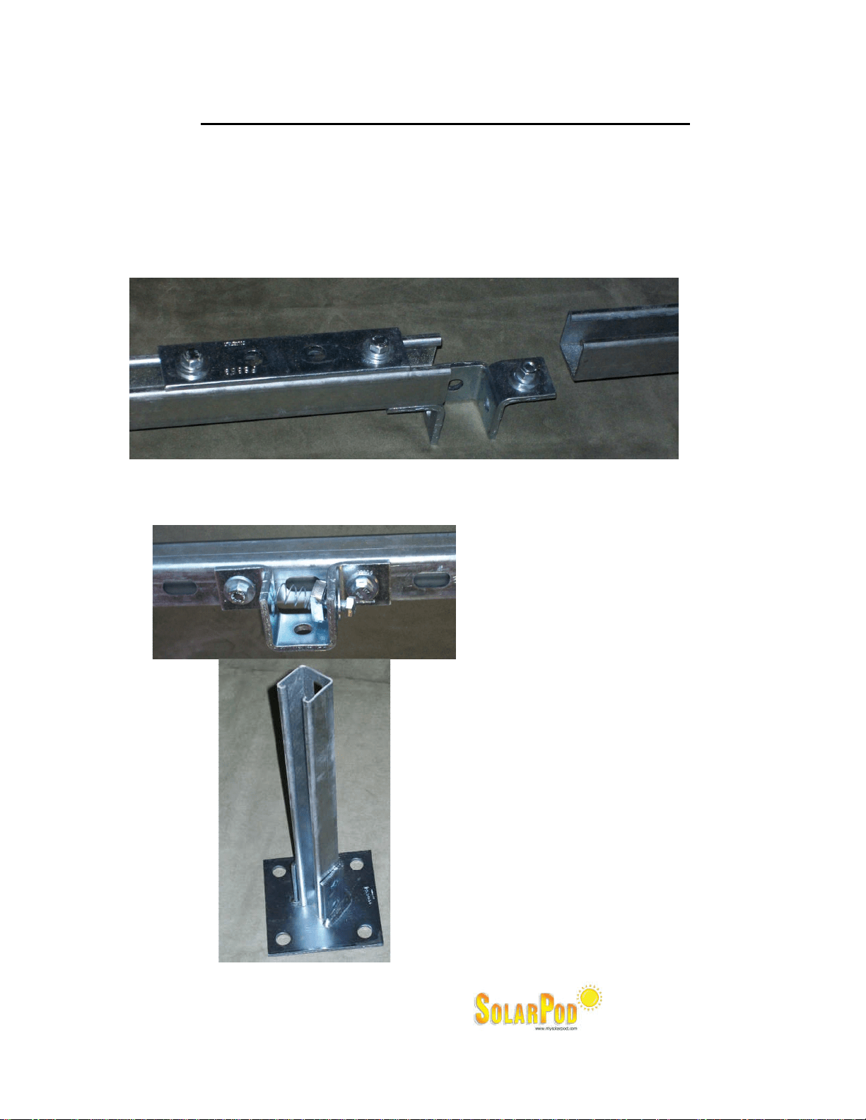
9. Then the “A1 & A2” AND “A3 & A4” will be connected using the splice bar (flat 4 hole plate in the
box). There are two splice bars given in the box with hardware.

Mouli Engineering Inc. © 2014; U.S. Patent No. 8,716,889 Rev. 8 May 23, 2014
10. Two grade 8 “gold” bolts are used to fasten the telescopic legs to the appropriate tile angle. Now
the whole SolarPod
TM
is all mechanically connected.
11. Now the electrical portion begins.
12. The A1 section has wire coiled up. Release this coil by cutting out the tie wrap. Extend the wire
all the way towards A4. Using the tie wraps provided, secure the wire to the frame. Ensure most
of the cable is tucked underneath the metal frames.
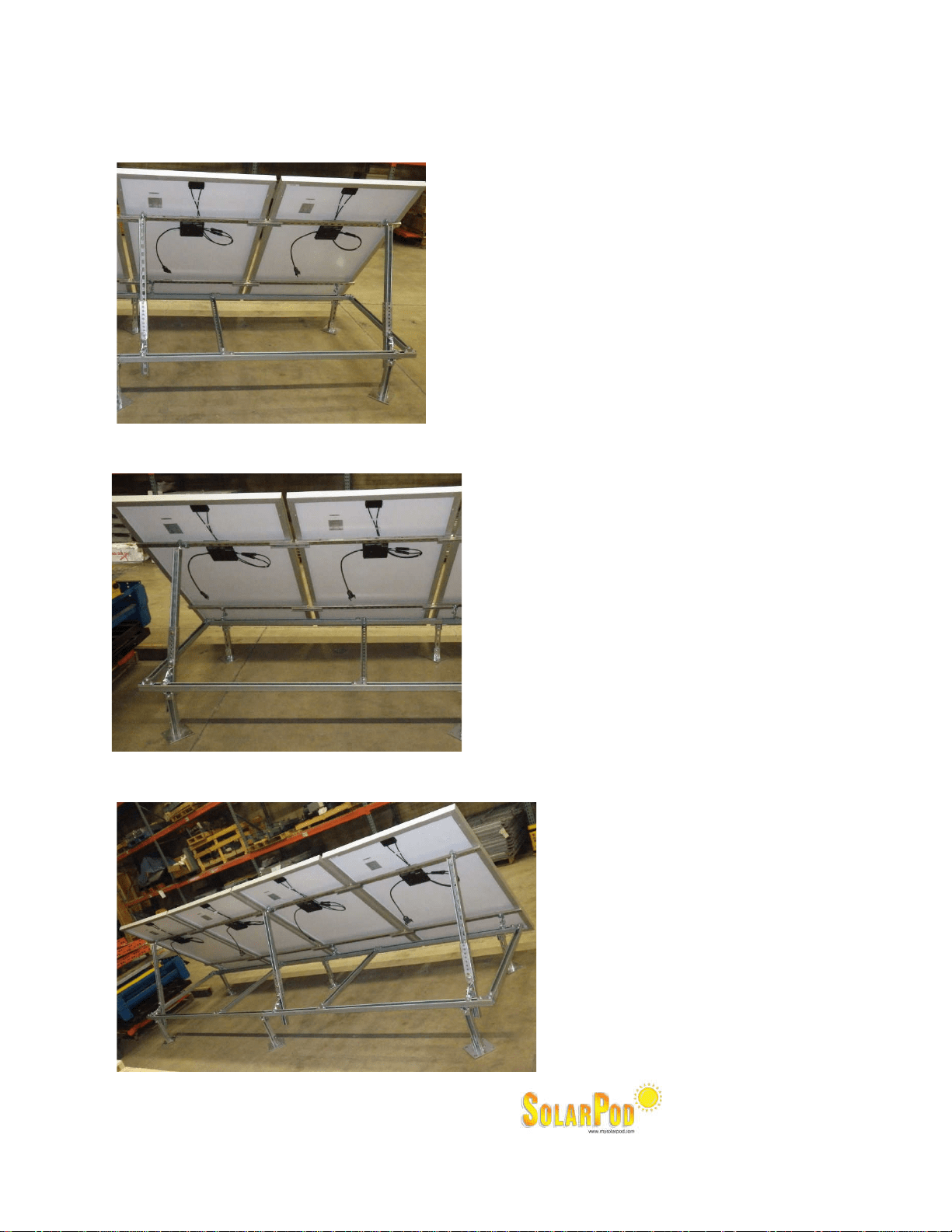
13. Connect the three micro-inverters in A2, A3 and A4 as shown in A1. Push all the way to ensure
that the connection is secure and tight.
14. Then we run the wire from the the facility using the four wire 240V / 30A adapter.
15. Connect the adapter to a dedicated 20A two pole circuit breaker and you are making solar power.
16. Run #6 ground wire through ground lug provided and use a ground rod appropriately distanced to
ground the SolarPod
◌
TM
Grid Tied.