Mouli Engineering © 2015 U.S.Patent 8,716,889; Manual Rev 15.0
SolarPod
◌TM
Standalone Manual
Dear SolarPod
◌TM
Standalone Customer,
Thank you for choosing SolarPod
◌TM
Standalone - and congratulations on your new, high-quality, high-tech
SolarPod
◌TM
Standalone product. SolarPod
◌TM
Standalone is a patented (U.S. Patent 8,716,889) device
and we are confident to serve your green energy needs through this scalable (add as you grow) product.
This introduction should provide you with general information about the equipment. Please read it
carefully to learn about the SolarPod
◌TM
Standalone product. This is the best way to get the most out of
all the advantages that it has to offer.
Please also note the safety information and the safety precautions for the product installation location.
Following all product instructions will ensure long-lasting quality and reliability. And these are the
essential ingredients for outstanding results.
Important Safety Instructions.
General This manual contains important instructions for the SolarPod
◌TM
Standalone, that must be
followed during installation and maintenance of the inverter. The SolarPod
◌TM
Standalone is designed per
NEC 2008 code, but as with all electrical and electronic equipment, certain precautions must be observed
when installing and/or operating the SolarPod
◌TM
Standalone. Only persons with electrical knowledge
must install the SolarPod
◌TM
Standalone.
To reduce the risk of personal injury and to ensure the safe installation and operation of the SolarPod
◌TM
Standalone, you must carefully read and follow all instructions & safety instructions.
This manual covers four SolarPod
◌TM
Standalone models – model #1003, model #1004, model # 1005.
Go to the model instructions for your purchased model system.
Safety Instructions
The following section “Safety Instructions” contains different Warnings. A Warning describes a hazard to
equipment or personnel. It calls attention to a procedure or practice, which, if not correctly performed or
adhered to, could result in damage to or destruction of part or all of the SolarPod
◌TM
Standalone and/or
other equipment connected to the SolarPod
◌TM
Standalone or personal injury.
All electrical installations must be made in accordance with the National Electrical Code, ANSI/NFPA 70, and
any other codes and regulations applicable to the installation site.
General Information
The SolarPod
◌TM
Standalone comes with attached solar panel data sheet and inverter data sheet.
Please review the data sheets thoroughly before installation at site.
WARRANTY
All manufactured items AND PRODUCTS provided OR installed as is. The implied warranties of
merchantability, FITNESS FOR A PARTICULAR PURPOSE, AND NON-INFRINGEMENT ARE excluded.
There are no warranties that extend beyond the description of the face hereof.
Company guarantees its workmanship against defects for 90 days from the date of sale to Customer (or
Dealer), and will remedy problems created by Company workmanship at no further charge to Customer
(or Dealer). In the event that a manufacturer’s system component should be discovered defective and
require replacement or repair, Company will arrange for the manufacturer to honor their warranty on the
defective component part. In the event of any defect in workmanship, covered by the 90 day
Mouli Engineering © 2015 U.S.Patent 8,716,889; Manual Rev 15.0
workmanship warranty provided herein by Company to Customer (or Dealer), Company or its authorized
agent shall be entitled to correct the faults at its own cost and expense. Company Products are sold
subject only to the applicable component manufacturer standard printed warranty in effect at the
time of sale and such warranty shall supersede and be in lieu of all other warranties express or
implied. Dealer is not authorized to assume, on Company's behalf, any liabilities in connection with
Dealer's sale of Product other than as set forth in such Company standard written warranty statement.
Dealer shall indemnify and hold Company harmless with respect to any Dealer representation beyond
those in such Company warranty.
Mouli Engineering warrants its SolarPod
◌TM
Standalone to be free of defects in workmanship, but makes no
warranty as to the installation, site safety, appearance or color. Since methods of installation and on-site
conditions are beyond our control and can affect performance, Mouli Engineering makes no other warranty,
expressed or implied. Mouli Engineering’s sole obligation shall be, at its option, to replace or refund the
purchase of the SolarPod
◌TM
Standalone proven to be defective on workmanship and Mouli Engineering
shall not be liable for any loss or damage.
SolarPod
◌TM
Standalone is pre-assembled for your convenience and safety. Some of the pre-assembled
components may require you to complete warranty registration. Please complete them and send it
directly to that specific components manufacturer.
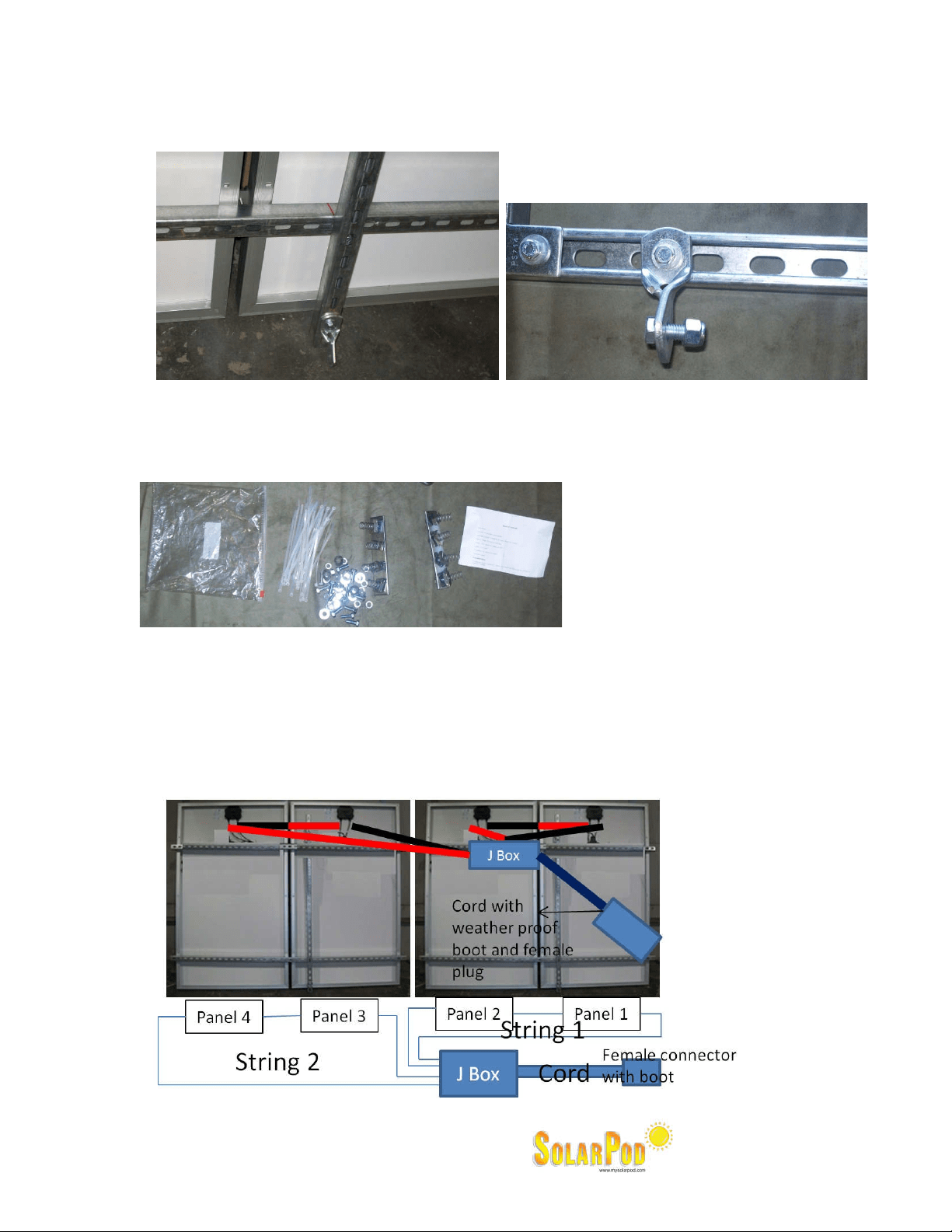
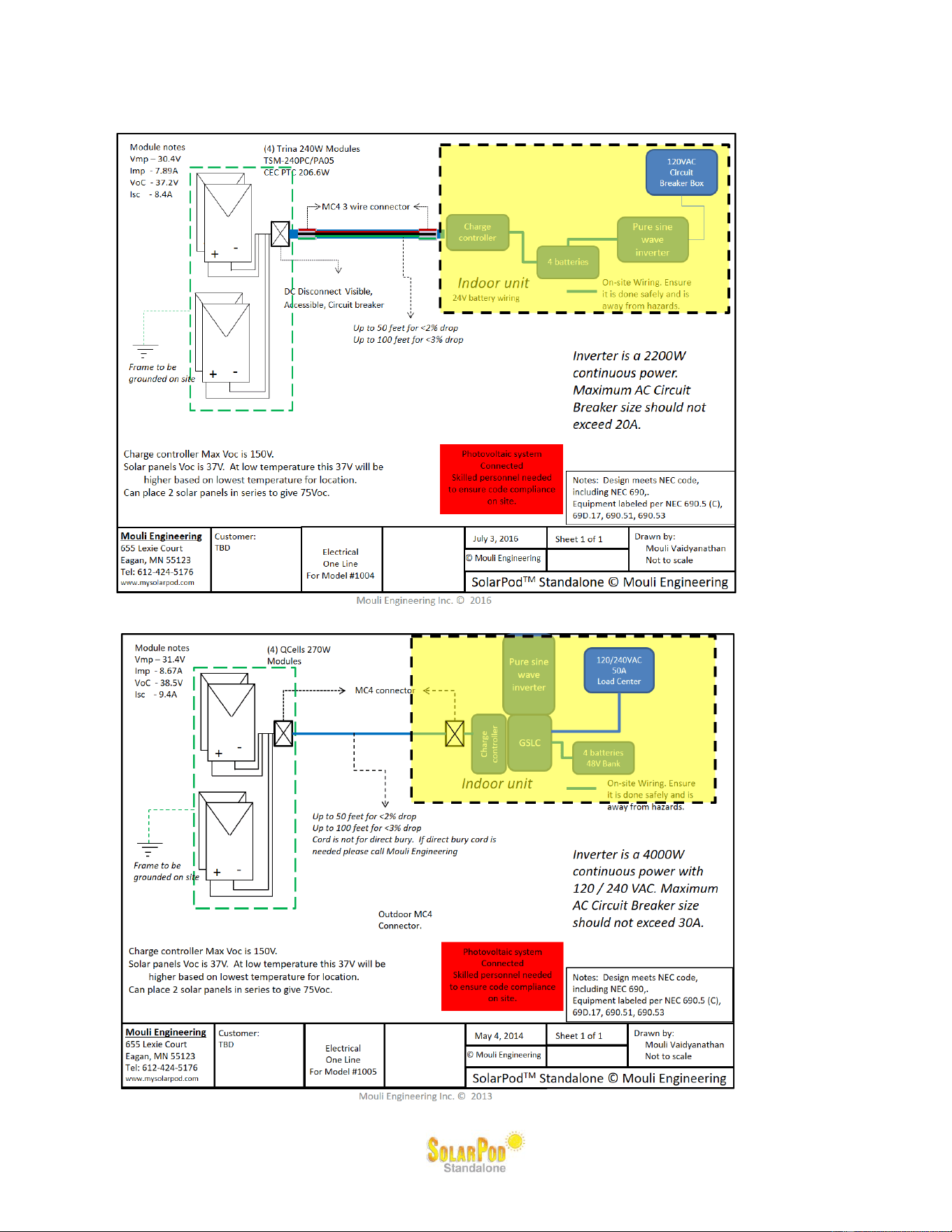
Wiring diagram
The wiring diagram for the SolarPod
◌TM
Standalone is given below. Skilled personnel will be required to
wire the system per local and national codes.
Model #1003
Mouli Engineering © 2015 U.S.Patent 8,716,889; Manual Rev 15.0
Model #1004
Model #1005
Mouli Engineering © 2015 U.S.Patent 8,716,889; Manual Rev 15.0
Grounding:
The system must be grounded using ground rods and bonded using metal and a minimum of #6 Cu
conductor.
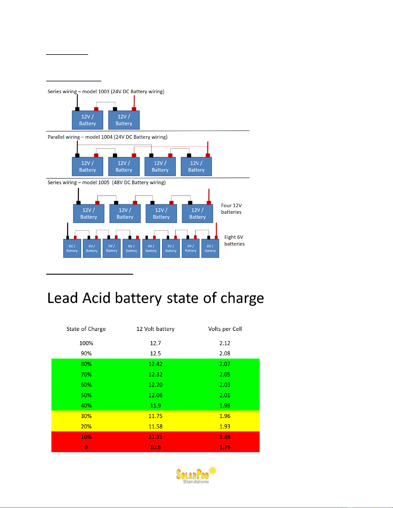
Battery Wiring:
Series and parallel wiring for the different SolarPod
◌TM
Standalone models.
Battery State of charge: The battery state of charge can be monitored on the Power Hub inverter.
The estimated voltage and the state of charge table is given below for one battery.

Mouli Engineering © 2015 U.S.Patent 8,716,889; Manual Rev 15.0
FM60-150 Settings (Model #1003):
The following settings are programmed on the FM60-150 charge controller.
1. You may want to attach the battery temperature sensor. This is not connected and is placed in
the “Warm” setting.
2. The battery supplied is a DM31 battery with 105Ah. The maximum charge current that this
battery can take is 30% of 105Ah which is 31.5A. Since the inverter is a 24V inverter, the two
batteries are placed in series. Hence a total current of 31.5A can be placed on the two batteries.
Since the charge controller maximum current is 60A, the settings on the charge controller is left to
the maximum charge current of 31A.
3. Battery voltage = 24V
4. Battery AH each = 105.
5. Battery temperature setting = Warm
6. Charge cycle = 3 stage.
FM60-150 Settings (Model #1004):
The following settings are programmed on the FM60-150 charge controller.
7. You may want to attach the battery temperature sensor. This is not connected and is placed in
the “Warm” setting.
8. The battery supplied is a DM31 battery with 105Ah. The maximum charge current that this
battery can take is 30% of 105Ah which is 31.5A. Since the inverter is a 24V inverter, the four
batteries are placed in series/parallel. Since the solar PV is 1000W, the maximum current is
1000 ÷ 24 = 42A max charge current. Since there are 2 battery banks (24V each), the maximum
current to each bank is 21A.
9. Battery voltage = 24V
10. Battery AH = 105 (two batteries so total is 210AH).
11. Battery temperature setting = Warm
12. Charge cycle = 3 stage.
FM60-150 Settings (Model #1005):
The following settings are programmed on the FM60-150 charge controller.
1. You may want to attach the battery temperature sensor. This is not connected and is placed in
the “Warm” setting.
2. The battery supplied is a DM31 battery with 105Ah. The maximum charge current that this
battery can take is 30% of 105Ah which is 31.5A. Since the inverter is a 48V inverter, the four
batteries are placed in series.
The SolarPod
TM
is a 960W system for Model 1005. Hence the current at 48V will be 20A. This is
below the battery max charging of 31.5A.
The SolarPod
TM
is a 1440W system for Model 1005. Hence the current at 48V will be 30A. This
is below the battery max charging of 31.5A.
3. Battery voltage = 48V
4. Battery AH = 105 (two batteries so total is 210AH).
5. Battery temperature setting = Warm
6. Charge cycle = 3 stage.
Mouli Engineering © 2015 U.S.Patent 8,716,889; Manual Rev 15.0
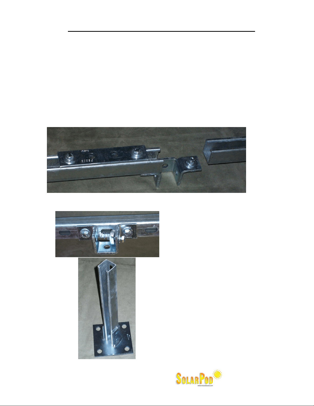
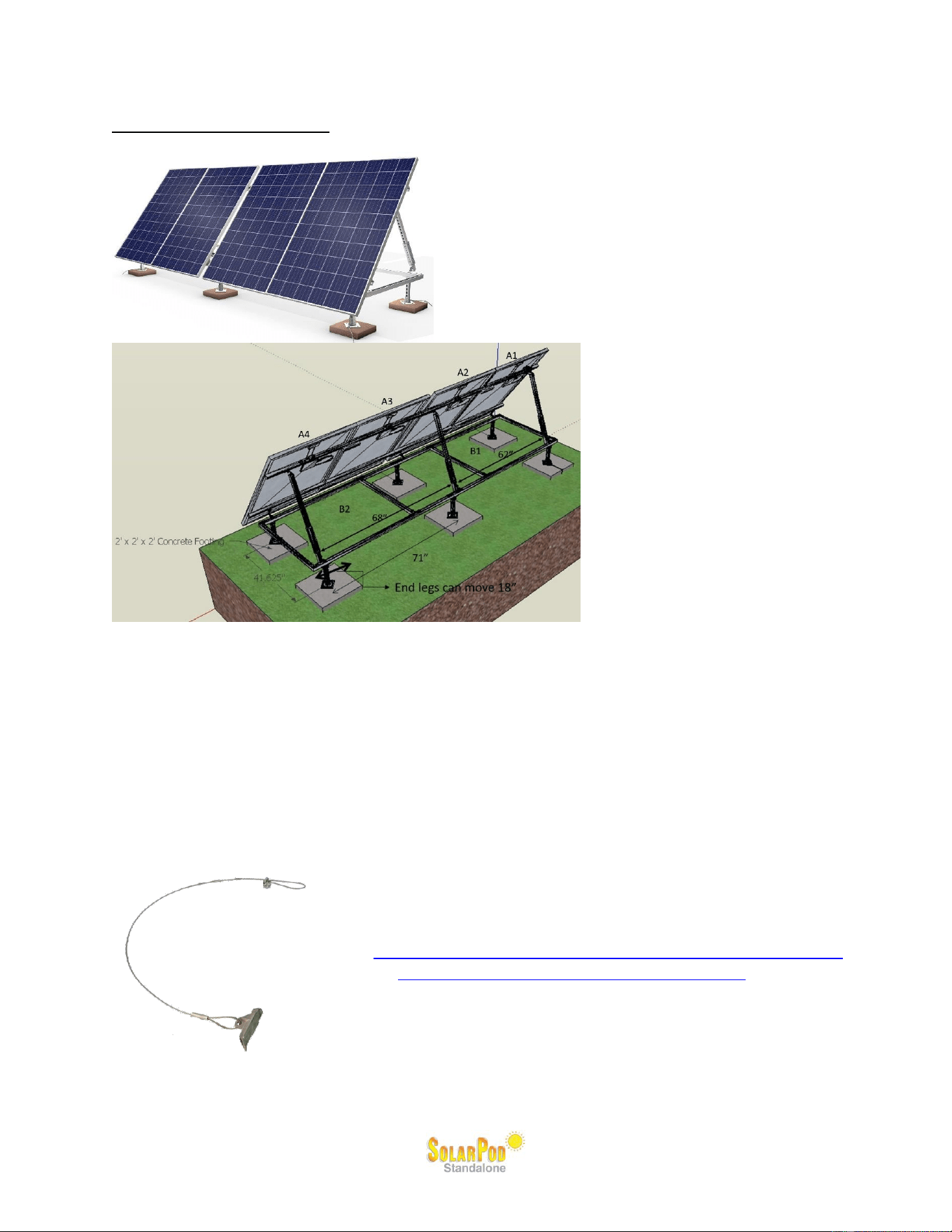
Structural requirements:
The center legs are fixed. The end legs can move 18” from each end.
At ground level, one can bolt the four legs of the SolarPod
◌TM
Standalone to the concrete slab.
Anchoring legs to the concrete slab is the recommended method on the ground.
Another option is to place 700 lbs of ballast. Place ballast so as to place most of the weight on
the steel members. Also insert 4 to 8 easy hook anchors to securely fasten the SolarPod
◌TM
Standalone to the hook anchors in the ground. The easy hook anchors typically come with a rod
and the anchor. The rod is used to drive the anchors deep into the ground and then hooked to the
SolarPod
◌TM
Standalone.
Photograph of an Easy hook anchor to the left. Installation of
Easy hook Anchors is given at:
http://www.shelterlogic.com/UserFiles/Documents/manuals/ac
cessories/05_10035_10036_10038_0B_BI.pdf
Another option is to place sufficient anchors to the
SolarPod
◌TM
Standalone so as to stay firm under 90 mph wind
loads. For other building height installations consult structural
PE.

Mouli Engineering © 2015 U.S.Patent 8,716,889; Manual Rev 15.0
Other ways to structurally fasten the SolarPod
◌TM
Standalone to the ground include the use of
(1) Screw anchors, (2) Diamond Piers and (3) Concrete base.
1. Screw anchors example:
http://www.farmtek.com/farm/supplies/prod;10052;;cpcc6250_CC6252.html
2. Diamond Pier Example : http://www.pinfoundations.com/videos.htm
Rebates: Three rebates are possible, Utility, Federal and State rebates. Please contact your
accountant for most accurate information.
1. Utility rebates:
Most utility companies give an incentive towards solar photovoltaic. The best website
that will give all the rebate information is: http://www.dsireusa.org/. You can then click
on the state and find your utility company servicing your area for more accurate up to
date information.
Wisconsin customers:
Utilities participating in solar rebate program (Focus on Energy):
http://www.focusonenergy.com/files/Document_Management_System/Misc/partic
ipatingutilities_list.pdf
Focus on Energy application form:
http://www.focusonenergy.com/files/Document_Management_System/Renewabl
es/renewableressolarelectric_applicationform.pdf
Minnesota customers:
Xcel Energy customers:
http://www.xcelenergy.com/Save_Money_&_Energy/For_Your_Home/Solar_Rew
ards/Solar_Rewards_-_MN
2. Federal Tax rebates:
Residential owners: http://www.irs.gov/pub/irs-pdf/f5695.pdf
Taxes on a Form 1040, Schedule C, and Form 5695
Business owners: http://www.irs.gov/pub/irs-pdf/f3468.pdf
For example single owner LLCs and Sole Proprietors use the same forms as individuals,
because they can file taxes on a Form 1040, Schedule C, and Form 5695, same as
individuals. And Sub-S corporations also use an IRS Form 1040 for individuals, because
the owners of a Sub-S corp pay the taxes for the Sub-S corporation on their personal tax
return. So then the same Form 5695 applies to these owners of Sub-S corp, LLCs, and
sole proprietorships. Some partnerships and professional assocations will also work this
way, but these questions should be referred to a tax professional advisor.
Here’s some business energy incentive tax information from the IRS website:
http://www.irs.gov/newsroom/article/0,,id=205018,00.html
http://www.irs.gov/newsroom/article/0,,id=209564,00.html
http://www.irs.gov/newsroom/article/0,,id=208318,00.html
3. State rebate:
State rebates can be found at http://www.dsireusa.org/
The above is for information. Please consult your accountant and tax advisor for most up to date
information. We do try to keep this above page current and will attempt to provide you with the most
general information.

Mouli Engineering © 2015 U.S.Patent 8,716,889; Manual Rev 15.0
Label as follows: More labeling than below to meet and exceed install workmanship.
1. Verify Label Installed on Inverter Panel:
THIS SERVICE PANEL IS ENERGIZED FROM Solar Photovoltaic source.
ONLY AUTHORIZED PERSONS WHO ARE FAMILIAR WITH THIS SYSTEM SHOULD
ATTEMPT TO DO SERVICE WORK ON IT.
2. Verify Label Installed near the PV System AC Disconnect
(Model #1003):
OPERATING AC VOLTAGE = __120V______
MAXIMUM AC OUTPUT OPERATING CURRENT = __12A_______
(Model #1004):
OPERATING AC VOLTAGE = __120V______
MAXIMUM AC OUTPUT OPERATING CURRENT = __17A_______
(Model #1005):
OPERATING AC VOLTAGE = __120V/240V______
MAXIMUM AC OUTPUT OPERATING CURRENT = __34A_______

Mouli Engineering © 2015 U.S.Patent 8,716,889; Manual Rev 15.0
Frequently asked questions
Do I need a foundation to set it on?
Not necessary. The easy hook anchors (4 of them) have to be placed on four legs. Each will should be
able to give at least 500 lbs of pull out force. If you think the soil is not tight and the pull out force is below
500 lbs, you can place ballast weights.
Do I need to anchor it so the wind won’t blow it over?
A total of 2000 lbs down force will be needed per SolarPod
◌TM
Standalone.
Do I need a ground rod for it?
Yes. The ground lug on the frame has to be connected to the ground rod.
Do I need to have a disconnect for it or is one on the unit.
A twist lock is also a disconnect mechanism.