Mouli Engineering Inc. © 2014; U.S. Patent No. 8,716,889 Rev. 5 May 4, 2014
SolarPod
◌
TM
Standalone Installation sequence
There will be one package (or palette) of materials. This palette contains six sections (A1, A2,
A3, A4, B1 & B2). A1, A2, A3, A4 are top panel portion and B1 and B2 are bottom portions. One box
will contain framing hardware and the other two boxes will contain inverter & charge controller pre-
assembled and one battery containing box. All tasks must be performed by qualified individuals
familiar and trained in wiring safety and electrical codes.
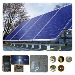
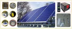
Framing the Solar panels is the first step as given below. Refer to the installation video for
mechanical framing installation. As this is a SolarPod
◌
TM
Standalone, the electrical installation in the
video will not be for the Standalone system. Ensure the solar panels face due south and have no (or
minimal) shading to maximize solar potential.
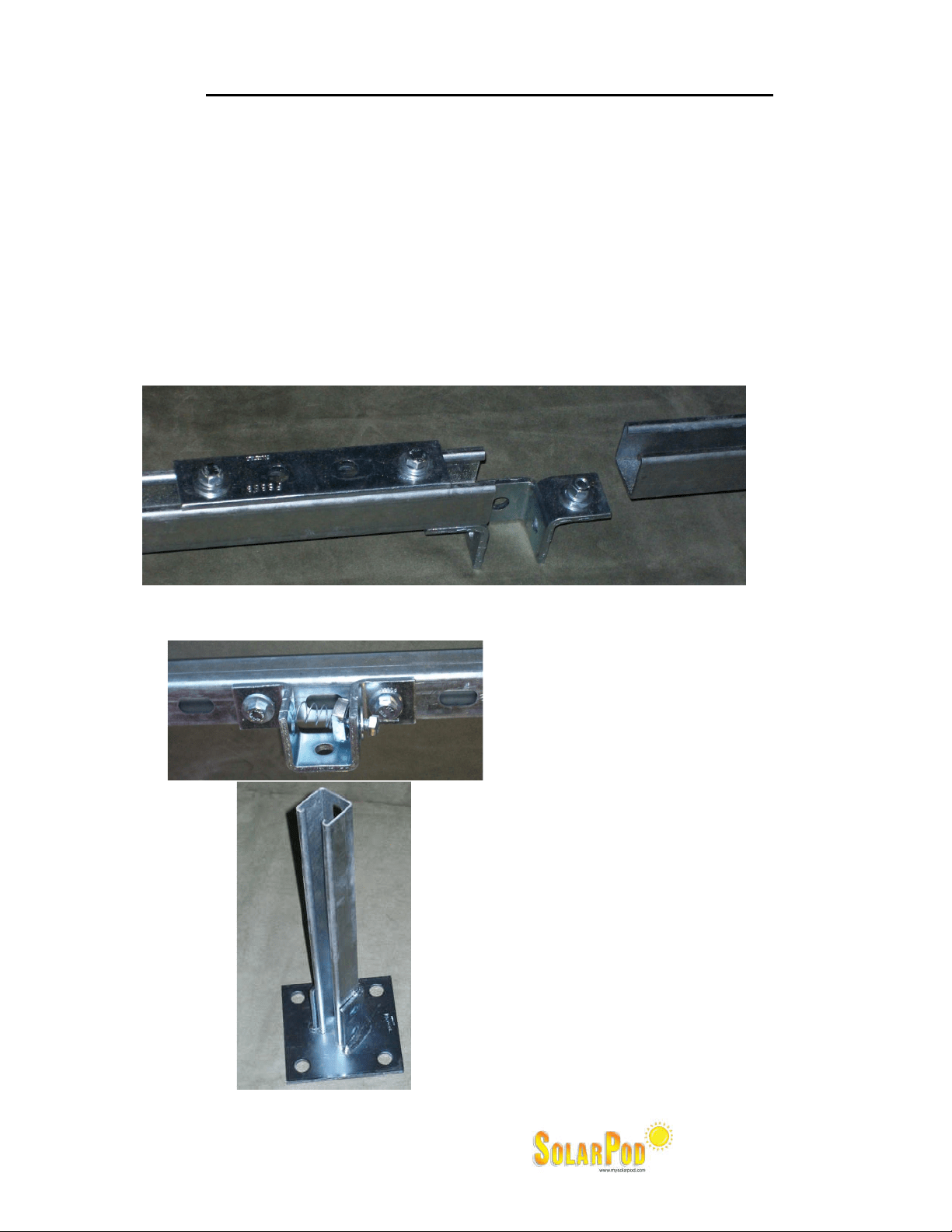
1. We will connect the B1 and B2 first using the leg bracket given and secure them. Secure the bolts
and tighten. Splice bar shown is not necessary for most applications and is placed only in
hurricane prone regions. The closeup of the splice is shown below. If you require splice bars for
your application please call SolarPod
◌
TM
.
2. Then the six feet’s will be attached to the bottom portion (B1 and B2) as shown below and tighten.
3. The ground is prepared using six patio
blocks and leveled.
4. The SolarPod
TM
bottom frame is placed on
the patio blocks. The Easy hook anchors
are driven into the four corner leg plates
anchoring them securely. Use additional
ways to secure the leg to the ground or
roof if you feel it is necessary.
5. Join A1 and A2 using the plate joint
provided. A1 can be identified easily
since it is the only solar panel with cable
that has been coiled and tied to the
frame.
6. Join A3 and A4 using the plate joint
provided.
Mouli Engineering Inc. © 2014; U.S. Patent No. 8,716,889 Rev. 5 May 4, 2014
7. The A1 & A2 will then be attached to the B1 side of the bottom portion through the hinge nut.
Closeup of the hinge is given below. Tighten the hinge. (A1&A2 is the panel top half with coil of
wire)
8. The A3 & A4 will then be attached to the B2 side of the bottom portion through the hinge nut.
Attach the hinge as in (7) above.
9. Then the “A1 & A2” AND “A3 & A4” will be connected using the splice bar (flat 4 hole plate in the
box). There are two splice bars given in the box with hardware.
10. Two grade 8 “gold” bolts are used to fasten the telescopic legs to the appropriate tile angle. Now
the whole SolarPod
◌
TM
Standalone is all mechanically connected.
11. Now the electrical portion begins.
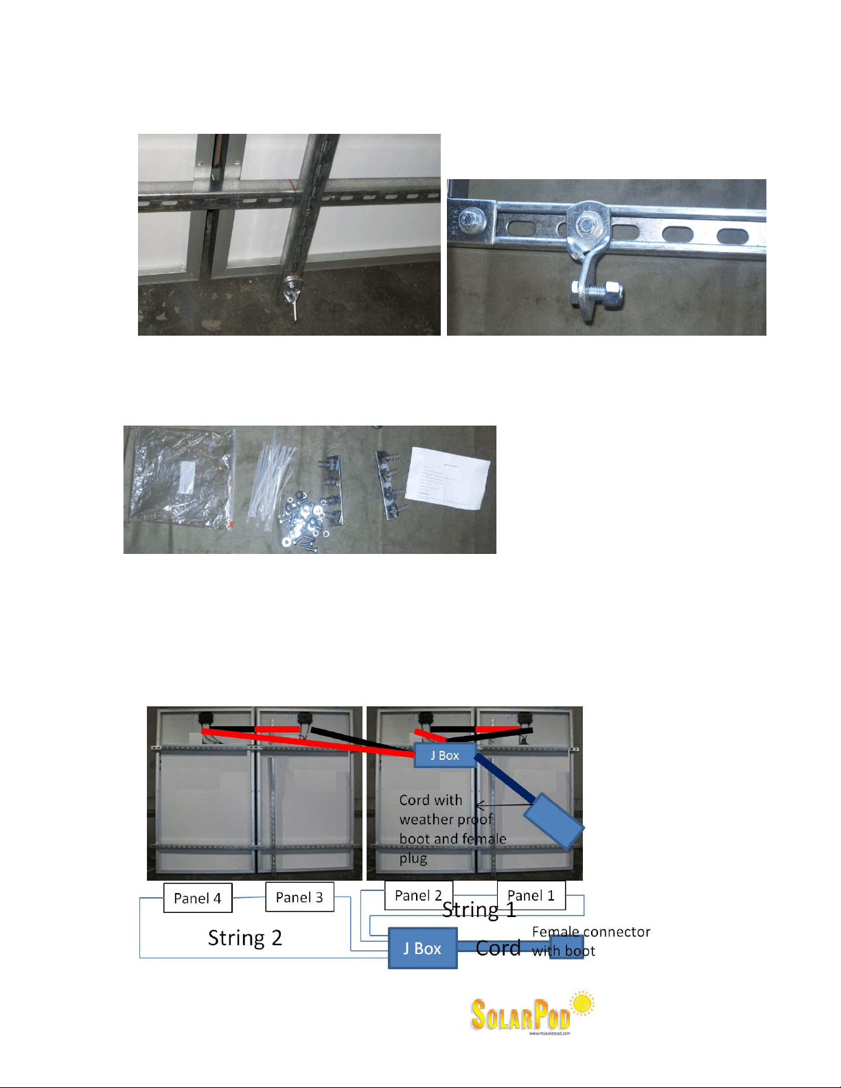
12. On the back of each panel, there will be a +ve and –ve wire. Connect the +ve of one to the –Ve
of the adjacent. The connections are shown pictorially in the figure below.
Four panel SolarPod
TM
for Model#1003, #1004 and #1005. String wiring per diagram below:
Mouli Engineering Inc. © 2014; U.S. Patent No. 8,716,889 Rev. 5 May 4, 2014
Six panel SolarPod
TM
for Model#1006. String wiring per diagram below:
13. The junction box will also have a weather proof twist lock female plug attached. Insert the twist
lock male plug extension with weather proof boot to the female plug with weather proof plug
attached to the junction box in the SolarPod
◌
TM
Standalone. The extension cord is not a direct
bury cord. Ways to protect the cord from any physical damage to the cords is the responsibility of
the installer.
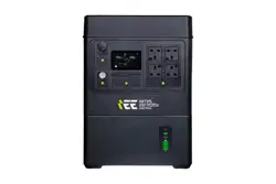
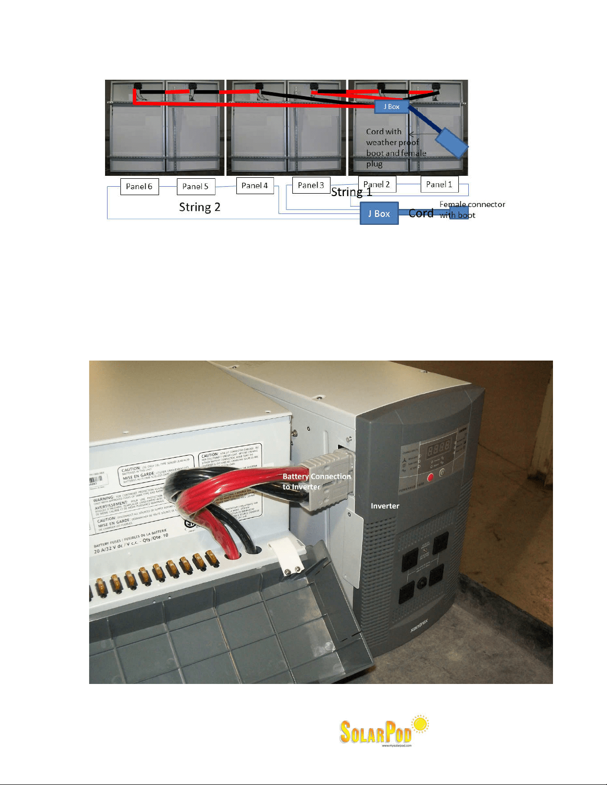
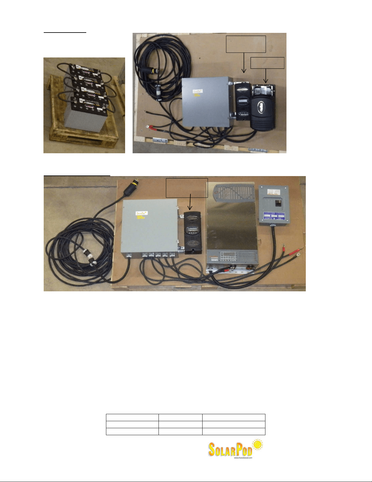
14. Attach the battery unit to the inverter before you connect the Solar panels.
Model #1003: Please see photo below as illustration.
Mouli Engineering Inc. © 2014; U.S. Patent No. 8,716,889 Rev. 5 May 4, 2014
Model #1004:
All terminals are labeled and must be torqued to enable good contact with the terminator of the
devices.
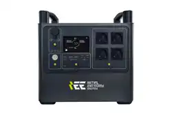
Model #1005 & 1006:
All terminals are labeled and must be torqued to enable good contact with the terminator of the
devices.
15. Attach the other end female without weather proof to the inverter with the male twist lock without
weather proof boot.
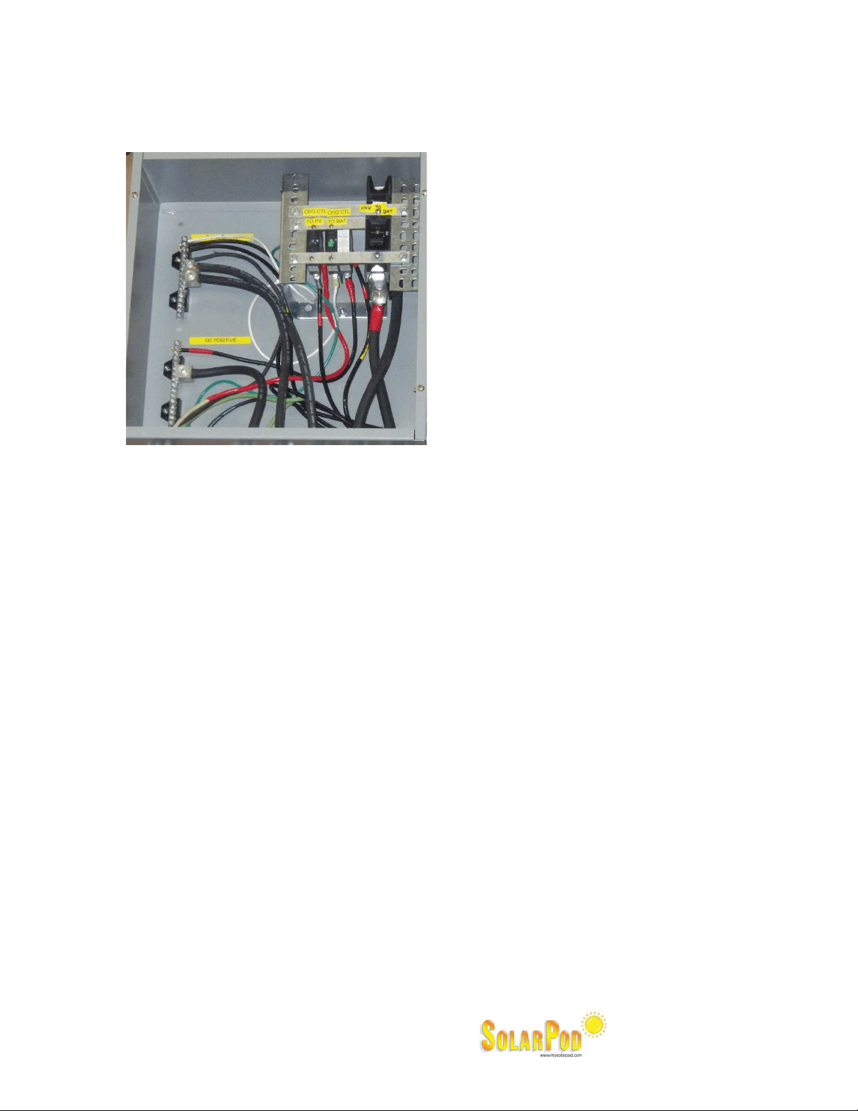
Connect the wires as labelled on the wire. Ensure the bolts are torqued for best contact.
16. Power up sequence:
a. Ensure all DC breakers in the DC Circuit Breaker Box are off.
b. Turn on the Charge Controller to DC Circuit Breaker.
c. Turn on the Charge Controller to Battery Circuit Breaker.
d. Program the charge controller.
i. Language – English
ii. Nominal System Voltage : Model #1004 – 12V ; Model 1005 & 1006 – 48V
e. Turn on the PV Array by connecting the twist lock plugs.
i. Check charging status. Must indicate charging if enough Sun light present.
ii. Verify in the inverter there is 120V output between L1 and Neutral.
iii. Program float and absorption voltages for the DTM31 battery on the charge controller as
follows:
Model Float voltage Absorption Voltage
1004 13.5V 14.1
1005 and 1006 54V 56.4V
Charge
Controller
Inverter
DC Breaker
Box
Bat
–
Bat+
Charge
Controller
Inverter
DC Breaker
Box
AC Breaker
Box
Connection
to Solar
Connection to
Solar
Mouli Engineering Inc. © 2014; U.S. Patent No. 8,716,889 Rev. 5 May 4, 2014
17. Run #6 ground wire through ground lug provided and use a ground rod appropriately distanced to
ground the SolarPod
◌
TM
Standalone.
The DC Breaker Box has a ground bar. The ground bar must be wired to a ground rod.
Ground bar must be wired with AWG #6 or larger wire to a code compliant ground rod.
18. Ensure the solar panels are facing due south and have no shading.
19. Allow some time to let the battery charge (about a day or two; may depend on weather and Sun
exposure).
20. Read the manuals for the charge controller and inverter and get familiar with them.
Model 1003: The outlets in the inverter can take only 120VAC and a maximum of 12A. The
inverter is a modified sine wave inverter.
Model 1004: The outlets in the inverter can take only 120VAC and a maximum of 17A. The
inverter is a pure sine wave inverter.
Model 1005 & 1006: The outlets in the inverter can take only 120VAC / 240VAC and a maximum
of 34A. The inverter is a pure sine wave inverter.
21. The warranties are from the manufacturers of the charge controller, inverter and solar panel
warranties.
22. Ground fault protection :
a. Model #1003: The Powerhub has intergral PV Ground Fault Protection (GFP) hence the GFP on
the MPPT60 has been disabled.
b. Model #1004, 1005 and 1006: The Charge controller to battery and the inverter to battery
are connected through a GFDI breaker.
23. System Voltage:
a. Model #1003 and 1004: 12V DC system. 12V batteries have to be hooked in parallel and not
in series.
b. Model #1005 and 1006: 48V DC system. 148V batteries have to be hooked in series.
24. You are now making SolarPod
TM
power. Enjoy the system.
GROUND