Loading ...
Loading ...
Loading ...
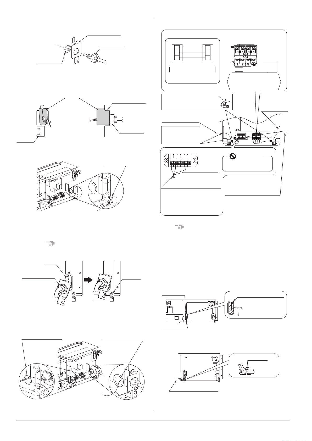
(2)
Attach the conduit to the conduit mounting plate (12).
Conduit mounting
plate (12)
Conduit
(eldsupply)
Lock nut
(eldsupply)
Fig. 24-1
• Attach the wire sealing pad (small) (10) to the conduit,
the wiring between the indoor and outdoor units, and the
ground wiring.
Conduit mounting
plate (12)
Conduit
mounting
plate (12)
Conduit
(ledsupply)
Wiresealingpad(small)(10)
Wiring between the
indoor and outdoor
units,groundwiring
(Viewedfromtheside)
Fig. 24-2
• Loosen the screws (2 points) in part A.
Screws
(2 points)
B
A
Wiringxture
Fig. 24-3
• Insert the hook part of the conduit mounting plate (12)
into part B and secure the conduit mounting plate (12)
with the screws loosened (2 points).
NOTE
Remove the wiring fixture if you have difficulty performing
this step.
Screws
(2 points)
Conduit mounting
plate (12)
Hook
Fig. 24-4
(3)
Connect the wiring into the electrical wiring box through
the wiring intake beside the electrical wiring box.
Wiring intake
(low voltage)
Remote controller
wiring
Wiring intake
(high voltage)
Wiring between
the indoor and
outdoor units
Ground wiring
Fig. 25
(4) Follow the instructions below and perform wiring in
the electrical wiring box.
F2
P1
P2
F1
Securelyxthewiringto
theprovidedwiringxture
withtheclamp(8).
Outdoorunit
Terminalblock Terminalblock
Connectionmethodfor
wiringbetweenthe
indoorandoutdoorunits,
andgroundwiring
Match the numbers
Connectionmethodofwiring
betweentheindoorandoutdoorunits
Terminalblock(X1M)
forwiringbetweenthe
indoorandoutdoorunits
Powersupplyterminals(X1M)
Indoorunit
1
2
3
1
2
3
Connectthewiringthrough
theelectricalwiringbox
uptothesheathedpart.
Wiringbetweentheindoorand
outdoorunits(highvoltage)
Groundwiring(highvoltage)
Remotecontrollerwiring
(lowvoltage)
Terminalblock(X2M)forremotecontrollerwiring
Remotecontrollerwiring
Nopolarity
<Remotecontrollerwiringmethod>
Do not connect wiring between
the indoor and outdoor units
(high voltage).
Prohibited
X1M
Remotecontrollerwiring
(Nopolarity)
Groundtheshieldpartof
shieldedwire.
RefertoNote2in
“9-2.WIRINGEXAMPLE”.
()
Wiringintake
(highvoltage)
Fig. 26
NOTE
Secure the wiring between the wiring intake and conduit with
the clamp (8) so that the wiring will not become loose.
(5) Mount the electrical wiring box cover and wrap the
wire sealing pad (small) (10) so that the wiring through
hole will be covered by the sealing pad.
• Seal the clearance around the wirings with putty or
insulatingmaterial(eldsupply).
(If insects and small animals get into the indoor unit,
short-circuiting may occur inside the electrical wiring box.)
Remote controller wiring
Wiring through
hole
Wire sealing pad (small) (10)
Wiringxture
Fig. 27
(6) Securelyxeachwiringwiththeprovidedclamp
material (8).
Remote controller wiring
Clamp (8)
Fig. 28
• See the installation manual supplied with the outdoor
unit.
13 English
Loading ...
Loading ...
Loading ...