Loading ...
Loading ...
Loading ...
8. DUCT WORK
Pay the utmost attention to the following items and
conduct the duct work.
• Check that the duct is not in excess of the setting range of
external static pressure for the unit. (Refer to the technical
datasheet for the setting range.)
• Attach a canvas duct each to the air outlet and air inlet so
that the vibration of the equipment will not be transmitted to
the duct or ceiling.
Use a sound-absorbing material (insulation material) for the
lining of the duct and apply vibration insulation rubber to the
suspension bolts.
• At the time of duct welding, perform the curing of the duct so
that the sputter will not come in contact with the drain pan for
thelter.
• If the metal duct passes through a metal lath, wire lath, or
plate of a wooden structure, separate the duct and wall
electrically.
• Be sure to heat insulate the duct for the prevention of
dew condensation. (Material: Glass wool or styrene foam;
Thickness: 1 inch (25mm))
• Besuretoattachtheeldsupplyairltertotheairinletofthe
unitoreldsupplyinletintheairpassageontheairsuction
side.(Besuretoselectanairlterwithaductcollection
efciencyof50weightpercent.)
• Explain the operation and washing methods of the locally
procuredcomponents(i.e.,theairlter,airinletgrille,andair
outlet grille) to the user.
• Locate the air outlet grille on the indoor side for the
prevention of drafts in a position where indirect contact with
people.
• The air conditioner incorporates a function to adjust the fan
to rated speed automatically. (10. FIELD SETTING)
Therefore, do not use booster fans midway in the duct.
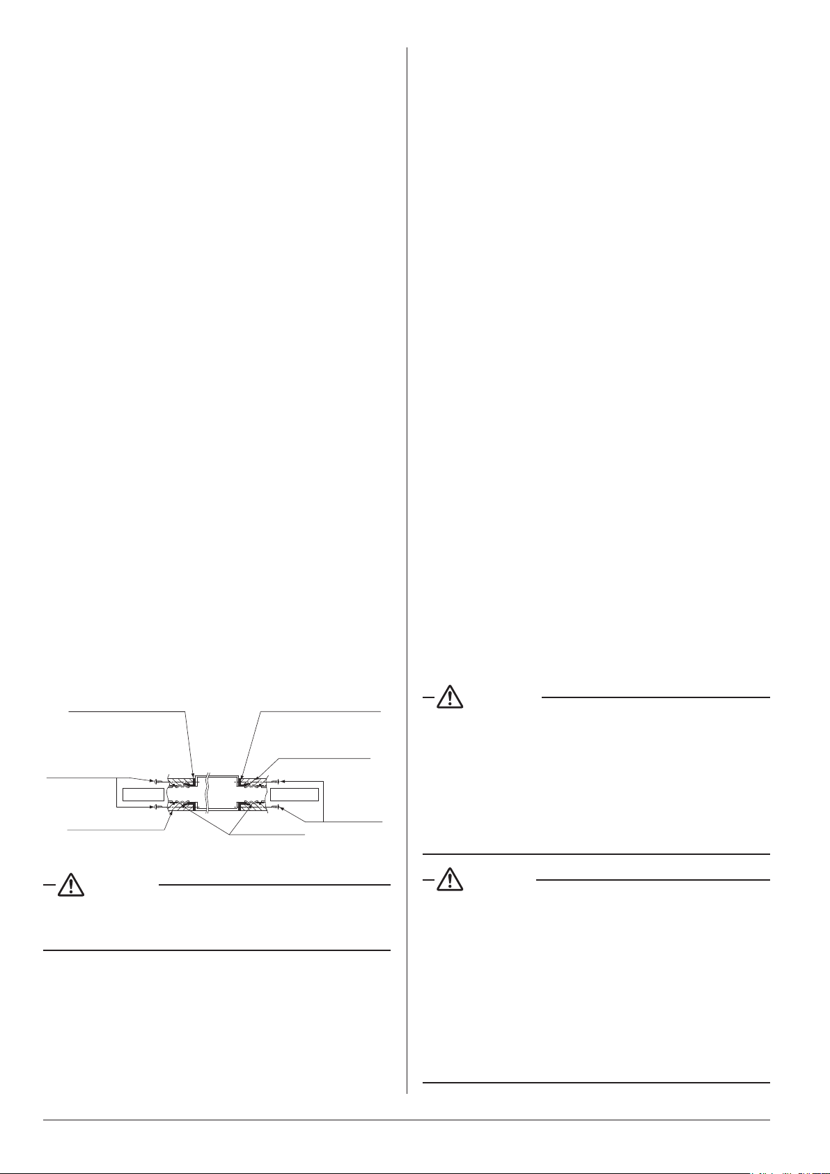
Connection method of ducts on air inlet and outlet sides.
• Connecttheeldsupplyductinalignmentwiththeinnerside
oftheange.
•
Connecttheangeandunitwiththeductangeconnection
screw (3).
• Wrapaluminiumtapearoundtheangeandductjointin
order to prevent air leakage.
Unit
Insulation material
(eldsupply)
Canvasduct
(eldsupply)
Flangeonairinletside
(providedwiththeunit)
Insulation material
(eldsupply)
Air inlet
Air outlet
Ductange
connection
screws(3)
Ductange
connection
screws(3)
Flangeonairoutletside
(providedwiththeunit)
Fig. 19
CAUTION
Connecttheangeandunitwiththeangeconnectionscrew
(3) regardless of whether the duct is connected to the air
inlet side.
9. ELECTRIC WIRING WORK
9-1 GENERAL INSTRUCTIONS
• Make certain that all electric wiring work is carried out by
qualiedpersonnelaccordingtotheapplicablelegislation
and this installation manual, using a separate dedicated
circuit.
Insufcientcapacityofthepowersupplycircuitorimproper
electricalconstructionmayleadtoelectricshockorare.
• Make sure to install a ground fault circuit interrupter.
Failuretodosomaycauseelectricshockandare.
• Do not turn on the power supply (branch switch, branch
overcurrentcircuitbreaker)untilalltheworksarenished.
• Multiple number of indoor units are connected to one
outdoor unit. Name each indoor unit as A-unit, B-unit ….. and
the like. When these indoor units are wired to the outdoor
unit, always wire the indoor unit to the terminal indicated
with the same symbol on the terminal block. If the wiring and
the piping are connected to the different indoor units and
operated, it will result in malfunction.
• Make sure to ground the air conditioner.
Grounding resistance should be according to applicable
legislation.
• Do not connect the ground wiring to gas or water pipings,
lightning conductor or telephone ground wiring.
• Gas piping .................Ignition or explosion may occur if
the gas leaks.
• Water piping ..............Hard vinyl tubes are not effective
grounds.
• Lightning conductor or telephone ground wiring ...............
Electric potential may rise abnormally if struck by a
lightning bolt.
• For electric wiring work, refer to also the “WIRING
DIAGRAM” attached to the electrical wiring box cover.
• Carry out wiring between the outdoor units, indoor units and
the remote controllers according to the wiring diagram.
• Carry out installation and wiring of the remote controller
according to the “installation manual” attached to the remote
controller.
• Do not touch the Printed Circuit Board assembly. It may
cause malfunction.
WARNING
• Do not use tapped wires, extension cords, or starburst
connections, as they may cause overheating, electric
shock,orre.
• Do not use locally purchased electrical parts inside the
product. (Do not branch the power for the drain pump,
etc., from the terminal block.) Doing so may cause electric
shockorre.
• Do not connect the power wire to the indoor unit. Doing so
maycauseelectricshockorre.
CAUTION
• When clamping wiring, use the included clamping
material to prevent outside pressure being exerted on
thewiringconnectionsandclamprmly.Whendoingthe
wiring, make sure the wiring is neat and does not cause
the electrical wiring box cover to stick up, then close the
coverrmly.
• Outside the unit, separate the low voltage wiring
(remote controller wiring) and high voltage wiring (wiring
between units, ground, and other power wiring) at least
2 in. so that they do not pass through the same place
together. Proximity may cause electrical interference,
malfunctions, and breakage.
11 English
Loading ...
Loading ...
Loading ...