Loading ...
Loading ...
Loading ...
English
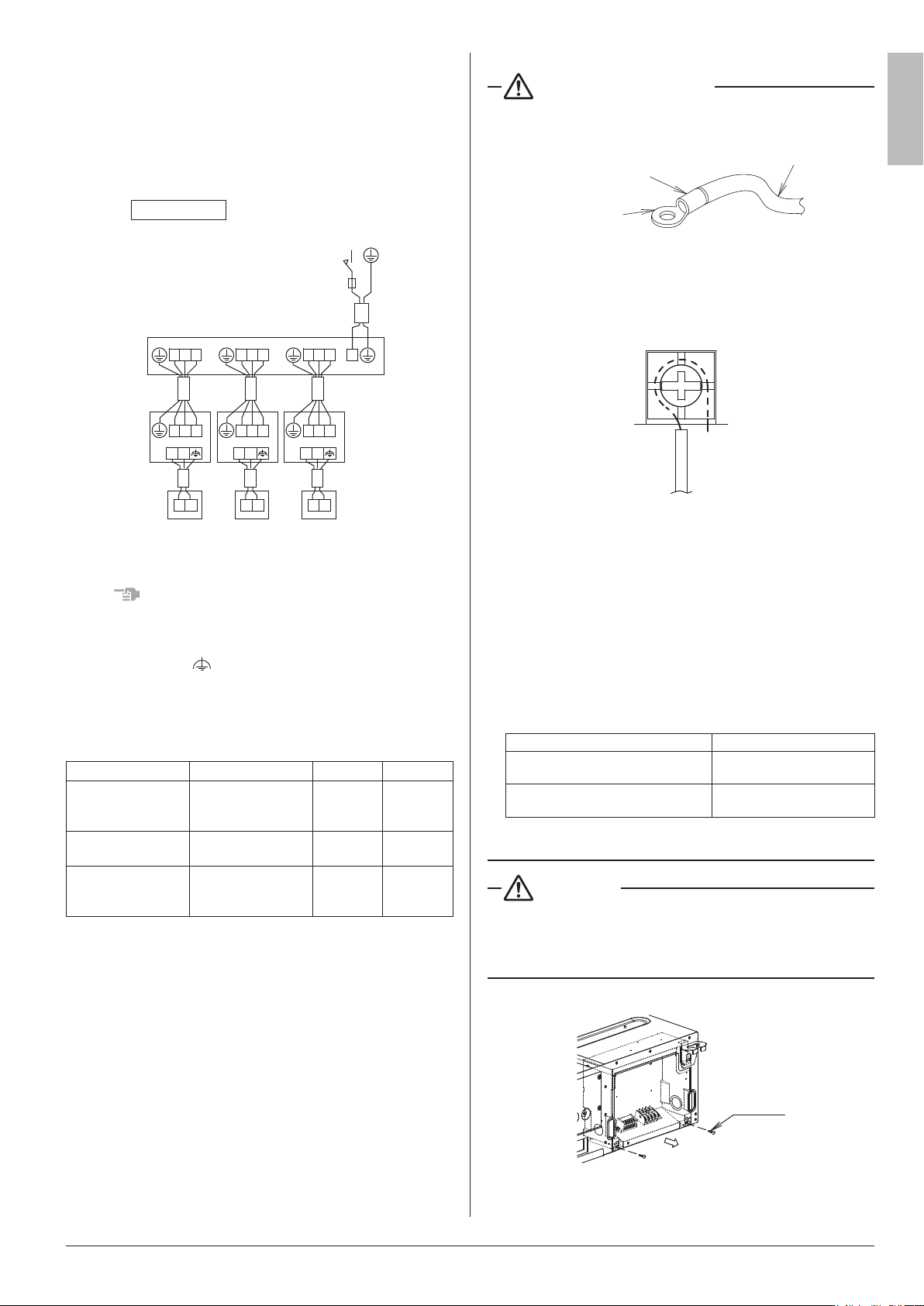
9-2 WIRING EXAMPLE
For the wiring of outdoor units, refer to the installation manual
attached to the outdoor units.
Conrmthesystemtype.
•
Multi system: 2 through 6 (The number of connectable units
will vary according to model) indoor units connect to 1 outdoor
unit. The indoor unit is controlled by remote controller connected
to each indoor unit.
Multi system
Main power supply
Main switch
1 2 3
1 2 3
P P1 2
P P1 2
1 2 3
1 2 3
P P1 2
P P1 2
1 2 3
1 2 3
P P1 2
P P1 2
Fuse
Outdoor unit
Indoor
unit
Indoor
unit
Indoor
unit
Remote controller
(Optional accessories)
Fig. 20
NOTE
1. All transmission wiring except for the remote controller
wires is polarized and must match the terminal symbol.
2. In case a shielding wire is to be used, connect a shielded
portion with the
of a remote controller terminal block.
(Also, connect the ground for the remote control to a
grounded metal part.)
9-3 SPECIFICATION FOR FIELD WIRE
Table 2
Wire Size Length (ft.)
Wiring between
units
Wire size and length
must comply with
local codes.
– –
Remote controller
wiring
Sheathed (2 wire)
AWG
18 - 16
Max.1640*
Wiring to ground
terminal
Wire size and length
must comply with
local codes.
– –
* This will be the total extended length in the system when doing group
control.
9-4 WIRING CONNECTION METHOD
CAUTION FOR WIRING
• For connection to the terminal block, use ring type crimp
style terminals with insulation sleeve or insulate the wirings
properly.
Insulation sleeve
Ring type crimp
style terminals
Wiring
Fig. 21
• Connect the terminal as shown in Fig. 22.
When installing a single core wire.
• Donotcarryoutsolderingnishwhenstrandedwirings
are used. (Otherwise, the loosening of wiring may result in
abnormal heat radiation.)
Fig. 22
(Abnormal heating may occur if the wirings are not tightened
securely.)
• Usetherequiredwirings,connectthemsecurelyandx
these wirings securely so that external force may not apply to
the terminals.
• Use a proper screw driver for tightening the terminal screws.
If an improper screw driver is used, it may damage the screw
head and a proper tightening cannot be car ried out.
• If a terminal is over tightened, it may be damaged.
Refer to the table shown below for tightening torque of
terminals.
Table 3
unit:lbf•ft(N•m)
Tightening torque
Terminal block for remote controller
(6P)
0.58 - 0.72 (0.79 - 0.98)
Terminal block for power supply
(4P)
0.87 - 1.06 (1.18 - 1.44)
• Donotcarryoutsolderingnishwhenstrandedwirings
are used.
WARNING
•
When wiring, form the wirings orderly so that the electrical wiring
box cover can be securely fastened. If the electrical wiring box
cover is not in place, the wirings may come out or be sandwiched
bytheboxandthelidandcauseelectricshockorare.
(1) Remove the electrical wiring box cover.
Screws
(2 points)
Fig. 23
English 12
Loading ...
Loading ...
Loading ...