Loading ...
Loading ...
Loading ...
16
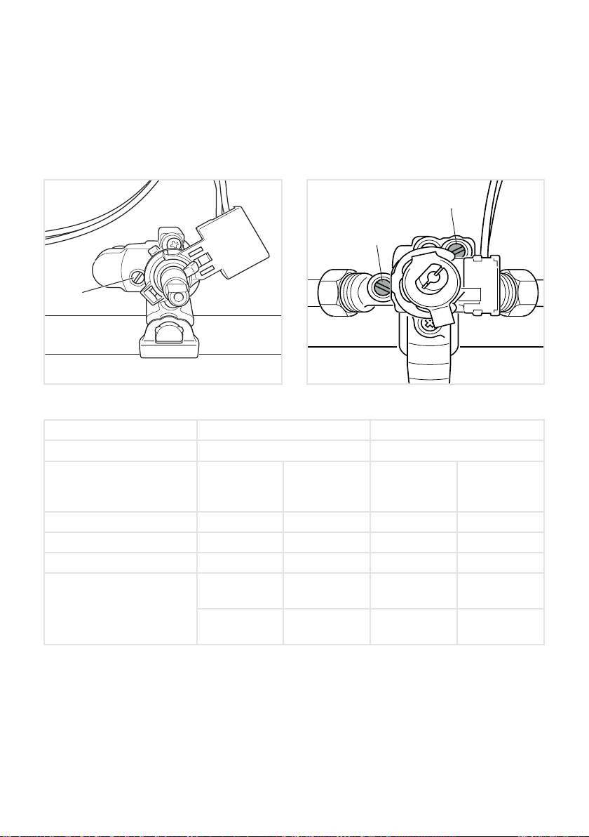
■ Using a screwdriver turn the screw “F2” until the correct setting is obtained (g. 15b).
Outside crowns of DUAL burner:
■ Light the DUAL burner.
■ Set the gas valve to the “minimum rate” position of the inner + outer crowns.
■ Remove the knob.
■ Using a screwdriver turn the screw “F3” until the correct setting is obtained (g. 15b).
Normally for ULPG, the regulation screw is tightened up.
TABLE FOR THE CHOICE OF THE INJECTORS
Natural gas ULPG
Test Point Pressure [kPa]
1.0 2.75
BURNER
Injector
Orice Dia.
[mm]
Gas
Consumption
[MJ/h]
Injector
Orice Dia.
[mm]
Gas
Consumption
[MJ/h]
Auxiliary (A) 0.85 3.60 0.53 3.60
Semi-rapid (SR) 1.12 6.30 0.70 6.30
Triple-ring (TR) 1.60 12.70 0.95 11.90
Dual (D)
0.85
(no.1 central)
3.60 (*)
0.50
(no.1 central)
3.20 (*)
1.15
(no.2 outer)
16.00 (**)
0.62
(no.2 outer)
13.00 (**)
(*)
Power calculated with only inner crown operating.
(**) Power calculated with inner and outer crowns operating.
LUBRICATION OF THE GAS VALVES
If a gas valve becomes stiff, it is necessary to dismantle it carefully and clean it with
petroleum spirit.
Specialist high temperature resistant grease should be used to lubricate the valve before
replacing.
The operations must be carried out by an authorised person/service agent.
F
Figure 15a
F1
G
H
Figure 15b
F2
F3
Loading ...
Loading ...
Loading ...