Loading ...
Loading ...
Loading ...
CAUTION
When the pumping has finished, close the Lo-lever of the
manifold valve completely and turn off the vacuum pump.
When you have pumped for over 15 minutes, please
confirm that the indicator of multimeter is on -1.0X10
-5
Pa
(-76cmHg)
Loosen and remove the nuts of service valves A and B to
open service valve A andB completely, then fasten nuts.
Disassemble the charge hose of service valve A, and
fasten the nut.
Both service valves should be open before test operation.
Each air conditioner has two service valves of different
sizes.(Refer to Fig.8-4)
Flare nut
Stopper
Cap
Valve body
Valve stern
9.2 Check the Leakage
Check all the joints with the leak detector or soap water. (Refer
Fig.9-5 as a reference illustration)
in the chart
A......Lo-stop valve
B......Hi-stop valve
C,D..Joints of the connecting pipe to the indoor unit.
B A
D
C
Check-point of indoor unit
Check-point of outdoor unit
-76 cmHg
Lo-lever
Hi-lever
Charge hose
Charge hose
Vacuum pump
Lo-lever
Manifold valve
Multi-meter
Pressure meter
Fig.9-3
Fig.9-4
9.3 Insulation
Be sure to completely insulate all the exposed parts of the flare
pipes.
Incomplete insulation may cause condensate.
Fig.9-5
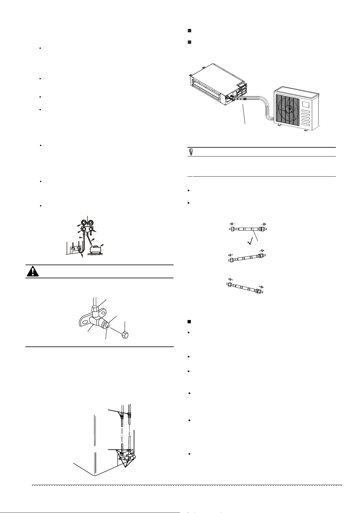
10. CONNECTIVE DIAGRAM
Orifice
Fig. 10-1
Fig. 10-2
For ensuring throttled efficiency, Please mount the Orifice as
horizontally as possible; and anti-shock rubber should be
wrapped at external of the Orifice for denoise.
NOTE
Please purchase the fittings according to the requirements in
the manual strictly.
Refer the diagram when installing.
Mark the data plate with the Orifice installed.(for some models)
Liquid side
Liquid side
Indoor
Indoor
Outdoor
Outdoor
X
Liquid side
Indoor
Outdoor
X
NOTE:the orifice should be horizontally installed.
Liquid side
Gas side
Expel the air with a vacuum pump(Refer to Fig.9-3)
3
(Please refer to its manual for the way of using manifold
valve)
18
installation manual
11. CONNECT THE DRAIN PIPE
Install the drainpipe of the indoor unit
Use a polyethylene tube as the drainpipe (out-dia. 1.14-1.22in
/29-31mm, in-dia. 0.984in/25mm). It could be bought from the
local market.
When extending drainpipe,tighten the connector with
water-proof tape to prevent it leakage.
Please lean the drainpipe down toward outdoor (outlet-side)
at a degree of over 1/ 50 to avoid water flowing back. And
please avoid any bulge.
Do not drag the drainpipe violently. Meanwhile, one
supportpoint should be set every 3.28~4.92ft/1~1.5m to
prevent the drainpipe from yielding. Or tie the drainpipe with
the connecting pipe to fix it.
If the outlet of the drainpipe is higher than the body's pump
joint, the pipe should be arranged as vertically as possible.
And the lift distance must be less than 21.65in/550mm,
otherwise the water can not be lifted completely and cause
overflow.(Only available for the unit with pump.)
The end of the drainpipe should be over 1.969in/50mm higher
than the ground , and do not immerse it in water. If you
discharge the water directly into sewage, be sure to make a
U-form aquaseal by bending the pipe up to prevent the smelly
gas entering the house through the drain pipe.
Loosen and remove the nuts of service valves A and B,
and connect the charge hose of the manifold valve with
the maintenance terminator of service valve A. (Be sure
that service valves A and B are both closed)
Connect the joint of the charge hose with the vacuum
pump.
Open the Lo-lever of the manifold valve completely.
Turn on the vacuum pump. At the beginning of pumping,
loosen the nut of service valve B a little to check whether
the air comes in (the sound of the pump changes, and
the indicator of compound meter turns below zero). Then
fasten the nut.
For more details visit www.mrcool.com
Loading ...
Loading ...
Loading ...