
Please read this manual carefully before installation and keep it for future reference.
Installation Manual
Please keep this manual where the operator can easily find it.
Inside you will find helpful hints on how to use and maintain your
unit properly.
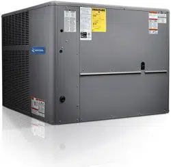
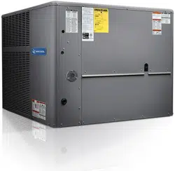
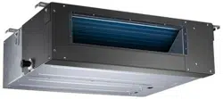
Olympus Series
Mid-Static Duct Air Handler
For more details visit www.mrcool.com

If used as MULTI unit, please refer to the Installation & operation manuals packed with outdoor unit.
Installation Manual
For more details visit www.mrcool.com
1
installation manual
Keep this manual where the operator can easily find them.
Read this manual attentively before starting up the units.
For safety reason the operator must read the following
cautions carefully.
Installation must be performed in accordance with the
requirement of NEC and CEC by authorized personnel only.
(Applicable to the North American area only)
1. SAFETY PRECAUTIONS
The safty precautions listed here are divided into two categories.
After completing the installation, make sure that the unit operates
properly during the start-up operation. Please instruct the customers
on how to operate the unit and keep it maintained.Also, inform
customers that they should store this installation manual along with
the owner's manual for future reference.
Be sure only trained and qualified service personnel to
install, repair or service the equipment.
Improper installation, repair, and maintenance may result in
electric shocks, short-circuit, leaks, fire or other damage to
the equipment.
If you do not follow these instrutions exactly, the unit may
cause property damage, personal injury or loss of life.
If you do not follow these instrutions exactly, the unit may
cause minor or moderate property damage, personal
injury.
CONTENTS PAGE
SAFETY PRECAUTIONS.......................................................................................1
INSTALLATION INFORMATION........................................................................... 2
ATTACHED FITTINGS.............................................................................................3
INSPECTING AND HANDLING THE UNIT.........................................................4
INDOOR UNIT INSTALLATION.................................................................................4
OUTDOOR UNIT INSTALLATION............................................................................11
INSTALL THE CONNECTING PIPE..................................................................15
REFRIGERANT PIPE..........................................................................................16
REFRIGERANT PIPE CONNECTION ...............................................................17
CONNECTIVE DIAGRAM......................................................................................18
CONNECT THE DRAIN PIPE..............................................................................18
FRESH AIR DUCT INSTALLATION.......................................................................19
CONTROL..............................................................................................20
WIRING.................................................................................................20
TEST OPERATION................................................................................................21
Install according to this installation instructions strictly.
If installation is defective, it will cause water leakage,
electrical shock and fire.
When installing the unit in a small room, take measures
against to keep refrigerant concentration from exceeding
allowable safety limits in the event of refrigerant leakage.
Contact the place of purchase for more information.
Excessive refrigerant in a closed ambient can lead to oxygen
deficiency.
Use the attached accessories parts and specified parts
for installation.
otherwise, it will cause the set to fall, water leakage,
electrical shock and fire.
Install at a strong and firm location which is able to
withstand the set' s weight.
If the strength is not enough or installation is not properly
done, the set will drop to cause injury.
The appliance must be installed 7.5ft / 2.3m above floor.
The appliance shall not be installed in the laundry.
Before obtaining access to terminals, all supply circuits
must be disconnected.
The appliance must be positioned so that the plug is
accessible.
The enclosure of the appliance shall be marked by word,
or by symbols, with the direction of the fluid flow.
For electrical work, follow the local national wiring
standard, regulation and this installation instructions. An
independent circuit and single outlet must be used.
If electrical circuit capacity is not enough or defect in
electrical work, it will cause electrical shock or fire.
Use the specified cable and connect tightly and clamp
the cable so that no external force will be acted on the
terminal.
If connection or fixing is not perfect, it will cause heat-up or
fire at the connection.
Wiring routing must be properly arranged so that control
board cover is fixed properly.
If control board cover is not fixed perfectly, it will cause
heat-up at connection point of terminal, fire or electrical
shock.
If the supply cord is damaged, it must be replaced by the
manufacture or its service agent or a similarly qualified
person in order to avoid a hazard.
An all-pole disconnection switch having a contact
separation of at least 0.118in / 3mm in all poles should be
connected in fixed wiring.
When carrying out piping connection, take care not to let
air substances go into refrigeration cycle.
Otherwise, it will cause lower capacity, abnormal high
pressure in the refrigeration cycle, explosion and injury.
Do not modify the length of the power supply cord or use
of extension cord, and do not share the single outlet with
other electrical appliances.
Otherwise, it will cause fire or electrical shock.
Carry out the specified installation work after taking into
account strong winds, typhoons or earthquakes.
Improper installation work may result in the equipment falling
and causing accidents.
WARNING
WARNING
CAUTION
For more details visit www.mrcool.com
To install properly, please read this "installation manual" at
first.
The air conditioner must be installed by qualified persons.
When installing the indoor unit or its tubing, please follow
this manual as strictly as possible.
If the air conditioner is installed on a metal part of the
building, it must be electrically insulated according to the
relevant standards to electrical appliances.
When all the installation work is finished, please turn on
the power only after a thorough check.
Regret for no further announcement if there is any change
of this manual caused by product improvement.
2. INSTALLATION INFORMATION
Ground the air conditioner.
Do not connect the ground wire to gas or water pipes,
lightning rod or a telephone ground wire. Inappropriate
grounding may result in electric shocks.
Be sure to install an earth leakage breaker.
Failure to install an earth leakage breaker may result in
electric shocks.
Connect the outdoor unit wires , then connect the indoor
unit wires.
You are not allowed to connect the air conditioner with the
power supply until the wiring and piping is done.
While following the instructions in this installation
manual, install drain piping in order to ensure proper
drainage and insulate piping in order to prevent
condensation.
Improper drain piping may result in water leakage and
property damage.
Install the indoor and outdoor units, power supply wiring
and connecting wires should be at least 3.3ft away from
televisions or radios in order to prevent image
interference or noise.
Depending on the radio waves, a distance of 3.3ft may not be
sufficient enough to eliminate the noise.
The appliance is not intended for use by young children
or infirm persons without supervision.
Don't install the air conditioner in the following
circumstance:
There is petrolatum existing.
There is salty air surrounding (near the coast).
There is caustic gas (the sulfide, for example) existing
in the air (near a hot spring).
The Volt vibrates violently (in the factories).
In buses or cabinets.
In kitchen where it is full of oil gas.
There is strong electromagnetic wave existing.
There are inflammable materials or gas.
There is acid or alkaline liquid evaporating.
Other special conditions.
If the refrigerant leaks during installation, ventilate the
area immediately.
Toxic gas may be produced if the refrigerant comes into the
place contacting with fire.
The temperature of refrigerant circuit will be high, please
keep the interconnection cable away from the copper
tube.
After completing the installation work, check that the
refrigerant does not leak.
Toxic gas may be produced if the refrigerant leaks into the
room and comes into contact with a source of fire, such as a
fan heater, stove or cooker.
INSTALLATION ORDER
Select the location;
Install the indoor unit;
Install the outdoor unit;
Install the connecting pipe;
Connect the drain pipe;
Wiring;
Test operation.
CAUTION
The appliance shall be installed in accordance with
national wiring regulations.
Do not operate your air conditioner in a wet room such
as a bathroom or laundry room.
An all-pole disconnection device which has at least
0.12in clearances in all poles , and have a leakage current
that may exceed 10mA, the residual current device (RCD)
having a rated residual operating current not exceeding
30mA, and disconnection must be incorporated in the
fixed wiring in accordance with the wiring rules.
2
installation manual
For more details visit www.mrcool.com
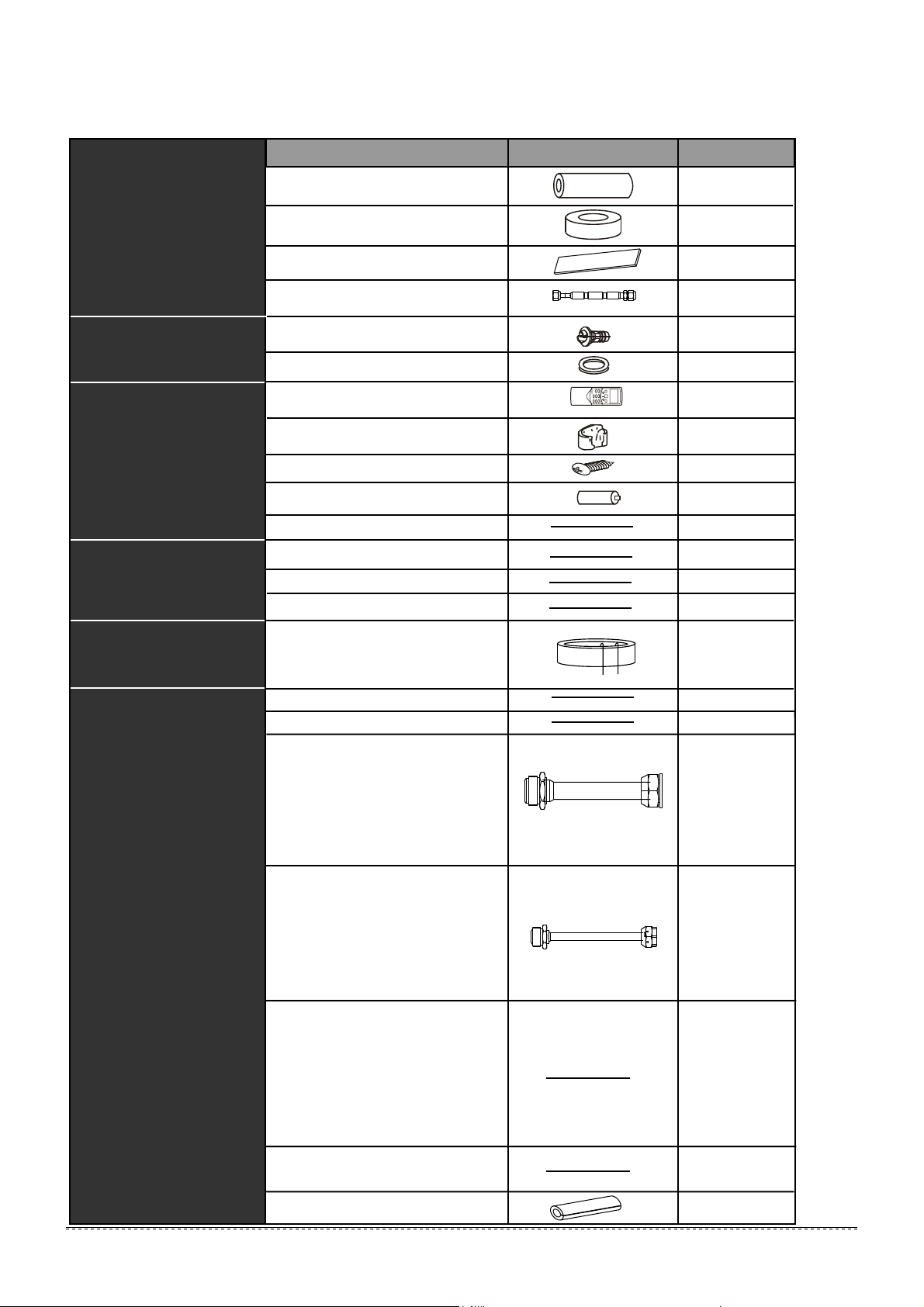
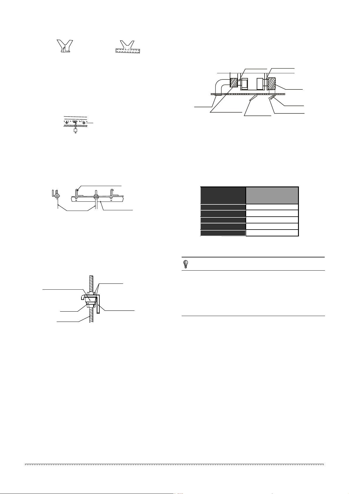
3. ATTACHED FITTINGS
Please check whether the following fittings are of full scope. If there are some spare fittings , please restore them carefully.
Table 3-1
QUANTITY
SHAPE
NAME
1. Soundproof / insulation sheath
11. Remote control manual
7. Remote control
8. Frame
10. Alkaline dry batteries (AM4)
2
12. Wire controller 1
1
1
1
1
1
1
2
1
1
1
Tubing & Fittings
Remote control & Its Frame
(Match with remote control)
(for some models)
Wire controller & Its Frame
(Match with wire controller)
(for some models)
Others
9. Mounting screw (ST2.9×10-C-H)
17. Installation manual
18. Transfer connector
(Φ12.7-Φ15.9) / (Φ0.5in-Φ0.63in)
(Packed with the indoor unit)
(NOTE: Pipe size differ from appliance
to appliance.To meet different pipe size
requirement, sometimes the pipe
connections need the transfer connector
to install on the outdoor unit.)
19. Transfer connector
(Φ6.35-Φ9.52) /(Φ0.25in-Φ0.375in)
(Packed with the indoor unit)
(NOTE: Pipe size differ from appliance
to appliance.To meet different pipe size
requirement, sometimes the pipe
connections need the transfer connector
to install on the outdoor unit.)
20. Transfer connector
(Φ9.52-Φ12.7) / (Φ0.375in-Φ0.5in)
(Packed with the indoor unit, used for
multi-type models only)
(NOTE: Pipe size differ from appliance
to appliance.To meet different pipe size
requirement, sometimes the pipe
connections need the transfer connector
to install on the outdoor unit.)
116. Owner‘s manual
14. Wire controller installation manual
13. Wire controller owner‘s manual
5. Drain joint
6. Seal ring
Drainpipe Fittings
(for cooling & heating)
2. Binding tape 1
3. Seal sponge
2
EMC & Its Fitting
(for some models)
15. Magnetic ring
(twist the electirc wires L and N
around the magnetic ring to five
circles)
1
L
N
4. Orifice
1
(on some models)
3
installation manual
21. Connecting wire for display (2M)
22. Cord protection rubber ring
1
(on some models)
1
(on some models)
1
(on some models)
1
(on some models)
1
(on some models)
For more details visit www.mrcool.com
CAUTION
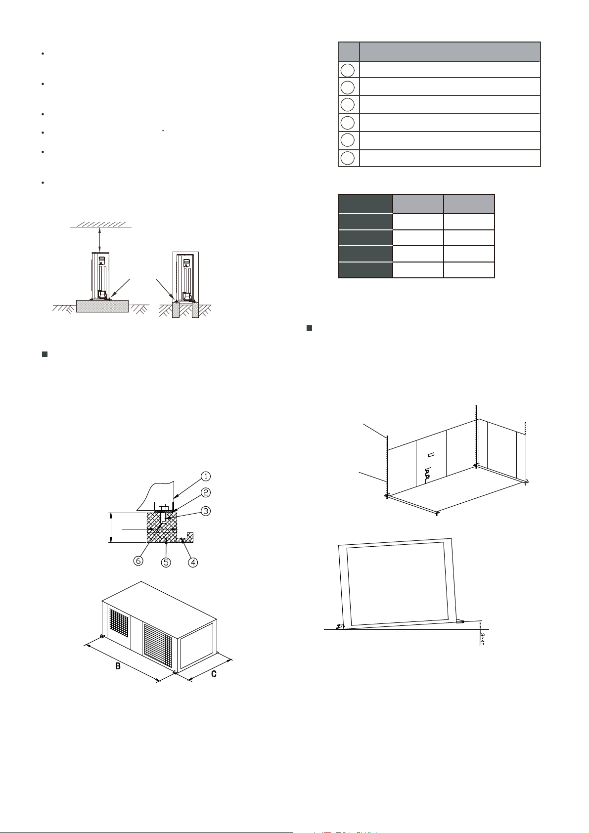
4. INSPECTING AND HANDLING THE UNIT
At delivery, the package should be checked and any damage should
be reported immediately to the service agent.
When handling the unit, take into account the following:
Fragile, handle the unit with care.
Keep the unit upright in order to avoid compressor
damage.
Choose on before hand the path along which the unit is to be
brought in.
Move this unit as originally package as possible.
When lifting the unit, always use protectors to prevent belt
damage and pay attention to the position of the unit’s centre
of gravity.
1
2
3
4
NOTE
5. INDOOR UNIT INSTALLATION
Keep indoor unit, outdoor unit, power supply wiring and
transmission wiring at least 3.3ft away from televisions
and radios. This is to prevent image interference and
noise in those electrical appliances. (Noise may be
generated depending on the conditions under which the
electric wave is generated, even if 3.3ft is kept.)
There is enough room for installation and maintenance.
The ceiling is horizontal, and its structure can endure the
weight of the indoor unit.
The outlet and the inlet are not impeded, and the
influence of external air is the least.
The air flow can reach throughout the room.
The connecting pipe and drainpipe could be extracted out
easily.
There is no direct radiation from heaters.
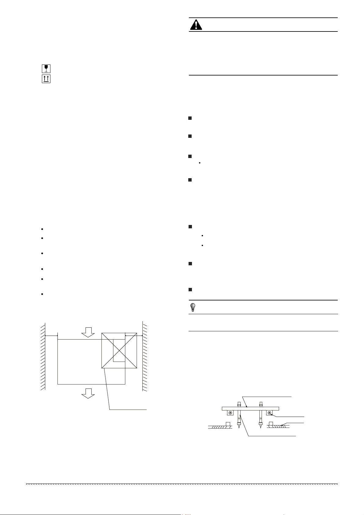
5.1 Installation place
The indoor unit should be installed in a location that meets
the following requirements:
5.2 Install the main body
Please refer to the following figures for positioning 4 screw
bolts.
Evaluate the ceiling construction and please install with
Ø10
/ Ø0.394in hanging screw bolts.
1 Installing Ø10/Ø0.394in hanging screw bolts. (4 bolts)
Consult the construction personnels for the specific procedures.
Do keep the ceiling flat. Consolidate the roof beam to avoid
possible vibration.
Carry out the pipe and line operation in the ceiling after finishing
the installation of the main body. While choosing where to start
the operation, determine the direction of the pipes to be drawn
out. Especially in case there is a ceiling, position the refrigerant
pipes, drain pipes, indoor & outdoor lines to the connection
places before hanging up the machine.
The installation of hanging screw bolts.
Cut off the roof beam.
Strengthen the place that has been cut off, and consolida-
tethe roof beam.
After the selection of installation location, position the refriger-
ant pipes, drain pipes,indoor & outdoor wires to the connection
places before hanging up the machine.
The installation of hanging screw bolts.
Fig.5-2
Fig.5-1
Confirm the minimum drain tilt is 1/100 or more
Wooden construction
Put the square timber traversely over the roof beam, then install
the hanging screw bolts. (Refer to Fig.5-2)
5.2.1
Timber over the beam
Roof beam
Hanging screw bolts
Ceiling
Maintenance room
checking orifice
600mmX600mm/23.622inX23.622in
300mm/11.811in or more
200mm/7.874in or more
4
installation manual
For more details visit www.mrcool.com
MODEL
(Btu/h)
Static Pressure
(Pa)
30
12
70
18
70
24
80
30~36
100
42~60
Fig.5-3
Fig.5-4
Fig.5-5
Fig.5-6
New concrete bricks
Inlaying or embedding the screw bolts. (Refer to Fig. 5-3)
For Original concrete bricks
Use embedding screw bold, crock and stick harness.
(Refer to Fig.5-4)
Steel roof beam structure
Install and use directly the supporting angle steel. (Refer to Fig.5-5)
5.2.2
5.2.3
5.2.4
(Blade shape insertion)
(Slide insertion)
Steel bar
Embedding screw bolt
(Pipe hanging and embedding screw bolt)
Hanging screw bolt
Hanging bolts
Supporting
angle steel
Overhanging the indoor unit
2
(1) Overhang the indoor unit onto the hanging screw bolts with
block.
(2) Position the indoor unit in a flat level by using the level indicator,
unless it may cause leakage.
Screw nut
Washer
Hanging
screw bolt
Overhang part
Shockproof cushion
3.
Air inlet and air outlet duct should be apart far enough to avoid
air passage short-circuit.
Recommended duct connection
Canvas tie-in Canvas tie-in
Air outlet
Isolation booth
Isolation booth
checking orifice
Air inlet
Air dust filter
Do not put the connecting duct weight on the indoor unit.
1.
When connecting duct, use inflammable canvas tie-in to prevent
vibrating.
2.
Change the fan motor static pressure corresponding to external
duct static pressure.
Insulation foam should be wrapped outside the duct to avoid
condensate and internal duct underlayer shall be added to reduce
the noise for special requirement.
3.
Fig.5-7
NOTE
Table.5-1
5. Please refer to the following static pressure to install
5.3 Duct and accessories installation
Install the filter(optional) according to air inlet size.
1.
Install the canvas tie-in between the body and duct.
2.
4.
5
installation manual
For more details visit www.mrcool.com
Air filter
Air filter
Electric control box
Electric control box
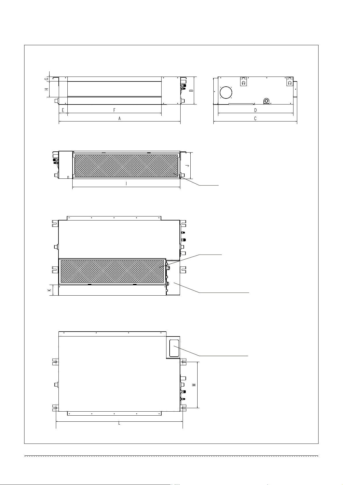
Dimension and air outlet size
Air inlet size
Position size of descensional ventilation opening
Size of mounted hook
Fig.5-8
Unit: in
The positioning of ceiling hole, indoor unit and hanging screw bolts
6
installation manual
For more details visit www.mrcool.com
NOTE
Air return flange
Side rail
Seal sponge
Dentilation panel
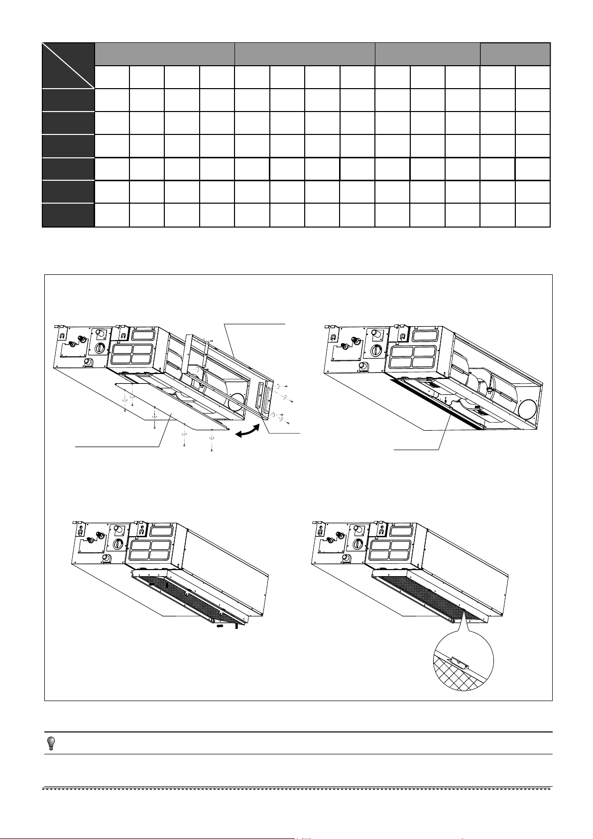
1.
Take off ventilation panel and flange, cut off the staples at
side rail.
2.
Stick the attached seal sponge as per the indicating place in
the following fig, and then change the mounting positions of
air return panel and air return flange .
3.
When install the filter mesh, please plug it into flange inclined
from air return opening, and then push up.
4.
The installation has finish, upon filter mesh which fixing
blocks have been insert to the flange positional holes.
Fig.5-9
How to adjust the air inlet direction? (From rear side to under-side.)
Table.5-2 Unit: in
air outlet opening size
air return opening size
Size of
mounted lug
Outline dimension
36.22 8.27 25 22.44 2.56 28.07 1.38 4.69 32.09 7.87 3.15 37.8 13.78
A B C D E F G H I J K L M
36.22 10.63
25
22.44 2.56 28.07 1.38 7.05 32.09 10.24
36.22 10.63
25
22.44 2.56 28.07 1.38 7.05 32.09 10.24
0.79 37.8 13.78
12~18
24
36
(small model)
All the figures in this manual are for explanation purpose only. They may be slightly different from the air
conditioner you purchased.The actual unit shall prevail.
44.88 10.63 30.51 27.95 2.56 36.73 1.38 7.05 40.75 10.24
0.79 46.46 19.29
1.77 48.82 19.69
30~36
42~60
47.24 11.81 34.06 31.5 3.15 38.11 1.58 8.03 43.07 11.34 1.77 48.82 19.69
12
27.56 8.27 25 22.44 2.56 19.41 1.38 4.69 23.43 7.87 3.15 29.13 13.78
7
installation manual
installation manual
For more details visit www.mrcool.com

5.9
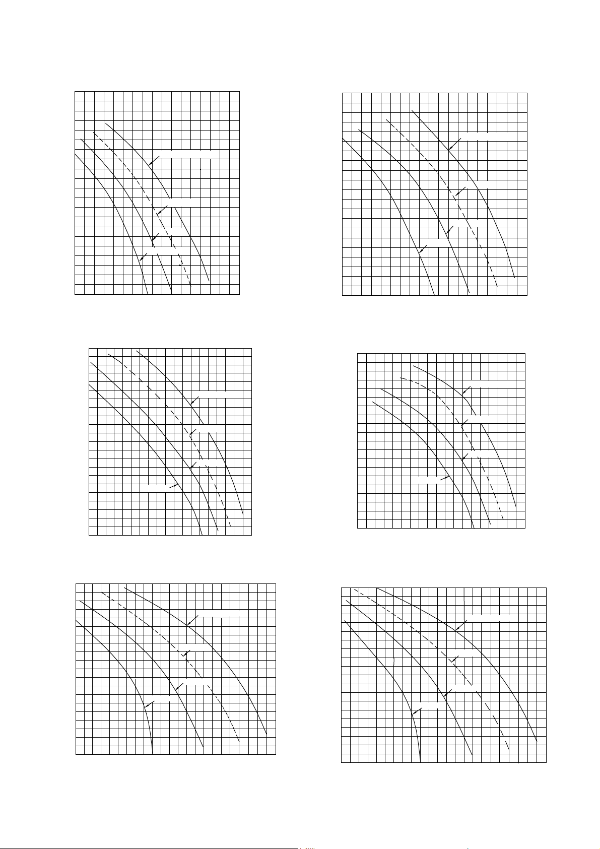
Fan performances
Static pressure curve(middle static pressure duct)
12K
18K
800
700
400300
Low speed
10
20
30
40
50
60
70
80
90
Pa
Air volume(m
/h)
3
External static pressure (Pa)
High speed
Mid speed
500
600
900
0
Super high speed
1200
Mid speed
High speed
External static pressure (Pa)
3
Air volume(m /h)
11001000900800700600
Pa
90
80
70
60
50
40
30
20
10
Low speed
200
300 400
500
Super high speed
24K 30K
700
1500
1200
Mid speed
High speed
External static pressure (Pa)
3
Air volume(m /h)
11001000900800
Pa
90
80
70
60
50
40
30
20
10
Low speed
1300 1400
Super high speed
2000
1800
Mid speed
High speed
External static pressure (Pa)
3
Air volume(m
/h)
1200
Pa
90
80
70
60
50
40
30
20
10
Low speed
1400 1600
2200
2400
Super high speed
8
installation manual
For more details visit www.mrcool.com
36K
36K(small model)
48K
60K
2400
2200
16001400
Low speed
10
20
30
40
50
60
70
80
90
1100
Air volume(m
/h)
3
External static pressure (Pa)
High speed
Mid speed
1200
1800
2000
Super high speed
Pa
3100
2800
19001600
Low speed
10
20
30
40
50
60
70
80
90
1000
Air volume(m
/h)
3
External static pressure (Pa)
High speed
Mid speed
1300
2200
2500
Pa
100
Super high speed
110
120
2500
2200
1300
Mid speed
High speed
External static pressure (Pa)
3
Air volume(m /h)
1000
Pa
90
80
70
60
50
40
30
20
10
Low speed
1600 1900
2800
3100
100
3400
Super high speed
110
120
Pa
high speed
1500
1400
1100
Low speed
Mid speed
3
Air volume(m /h)
1000
1200 1300
1600
1700
10
20
30
40
50
External static pressure (Pa)
60
70
80
1800
900
9
installation manual
For more details visit www.mrcool.com
Static pressure curve(high static pressure duct)
18k
Mid speed
High speed
External static pressure (Pa)
14001300
1200
1100
1000
Pa
90
80
70
60
50
40
30
20
10
Low speed
700
Super high speed
800
900
1500
24K
Mid speed
High speed
External static pressure (Pa)
14001300
1200
1100
1000
Pa
90
80
70
60
50
40
30
20
10
Low speed
700
Super high speed
800
900
1500
1600
3
Air volume(m
/h)
3
Air volume(m
/h)
30K
Mid speed
High speed
External static pressure (Pa)
2000
1800
16001400
1200
Pa
90
80
70
60
50
40
30
20
10
Low speed
600
Super high speed
800
1000
2200
2400
3
Air volume(m
/h)
100
36K
Mid speed
High speed
External static pressure (Pa)
20001800
160014001200
Pa
180
160
140
120
100
80
60
40
20
Low speed
600
Super high speed
800
1000
2200
2400
3
Air volume(m
/h)
48K
Mid speed
High speed
External static pressure (Pa)
3200
3000
2800
2600
2400
Pa
180
160
140
120
100
80
60
40
20
Low speed
800
Super high speed
1000
2200
3400
3600
3
Air volume(m
/h)
2000
1600
60K
Mid speed
High speed
External static pressure (Pa)
32003000
2800
2600
2400
Pa
180
160
140
120
100
80
60
40
20
Low speed
800
Super high speed
1000
2200
3400
3600
3
Air volume(m
/h)
2000
1600
10
installation manual
For more details visit www.mrcool.com
mmmm
B
C
D
E
F
Fig.6-2
Fig.6-4
Fig.6-3
A
H
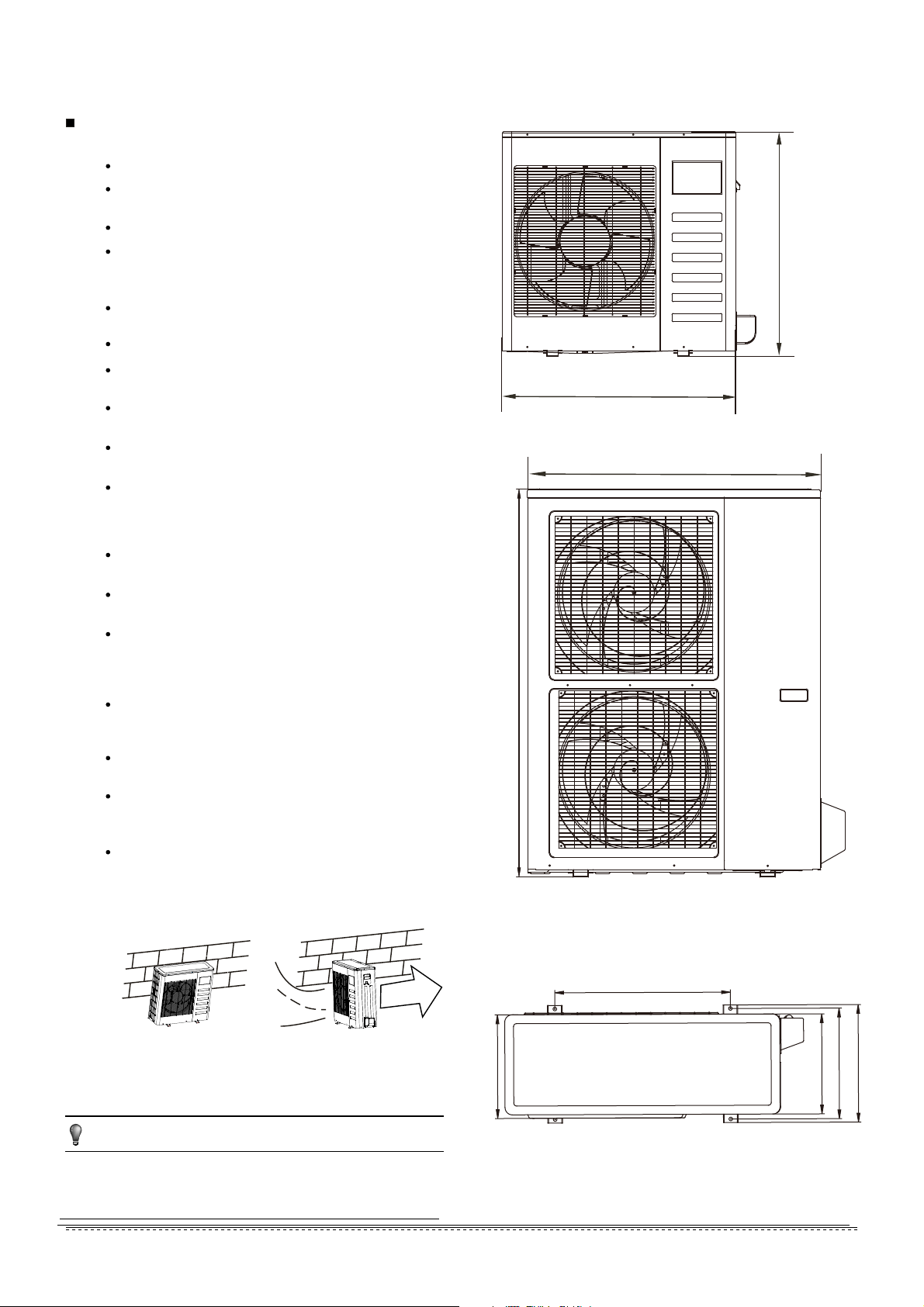
A
H
1. Split type outdoor unit
6.2 Figure of body size
NOTE
6.1 Installation Place
6. OUTDOOR UNIT INSTALLATION
There is enough room for installation and maintenance.
The air outlet and the air inlet are not impeded, and can
not be reached by strong wind.
It must be a dry and well ventilating place.
The support is flat and horizontal and can stand the
weight of the outdoor unit. And will no additional noise or
vibration.
Your neighborhood will not feel uncomfortable with the
noise or expelled air.
It is easy to install the connecting pipes or cables.
Determine the air outlet direction where the discharged air
is not blocked.
There is no danger of fire due to leakage of inflammable
gas.
The piping length between the outdoor unit and the indoor
unit may not exceed the allowable piping length.
In the case that the installation place is exposed to strong
wind such as a seaside, make sure the fan operating
properly by putting the unit lengthwise along the wall or
using a dust shield.(Refer to Fig.6-1)
If possible, do not install the unit where it is exposed to
direct sunlight.
If necessary, install a blind that does not interfere with the
air flow.
During heating mode, water drains off the outdoor unit.
The condensate should be well drained away by the drain
hole to an appropriate place, so as not to interfere other
people.
Select the position where it will not be subject to snow
drifts, accumulation of leaves or other seasonal debris. If
unavoidable, please cover it with a shelter.
Locate the outdoor unit as close to the indoor unit as
possible.
If possible, please remove the obstacles nearby to prevent
the performance from being impeded by too little of air
circulation.
The minimum distance between the outdoor unit and
obstacles described in the installation chart does not
mean that the same is applicable to the situation of an
airtight room. Leave open two of the three directions
(M,N,P) (Refer to Fig.6-5)
The outdoor unit should be installed in the location that
meets the following requiements:
All the figures in this manual are for explanation purpose only.
They may be slightly different from the air conditioner you
purchased.The actual uint shall prevail.
Fig.6-1
X
O
Strong wind
11
installation manual
For more details visit www.mrcool.com
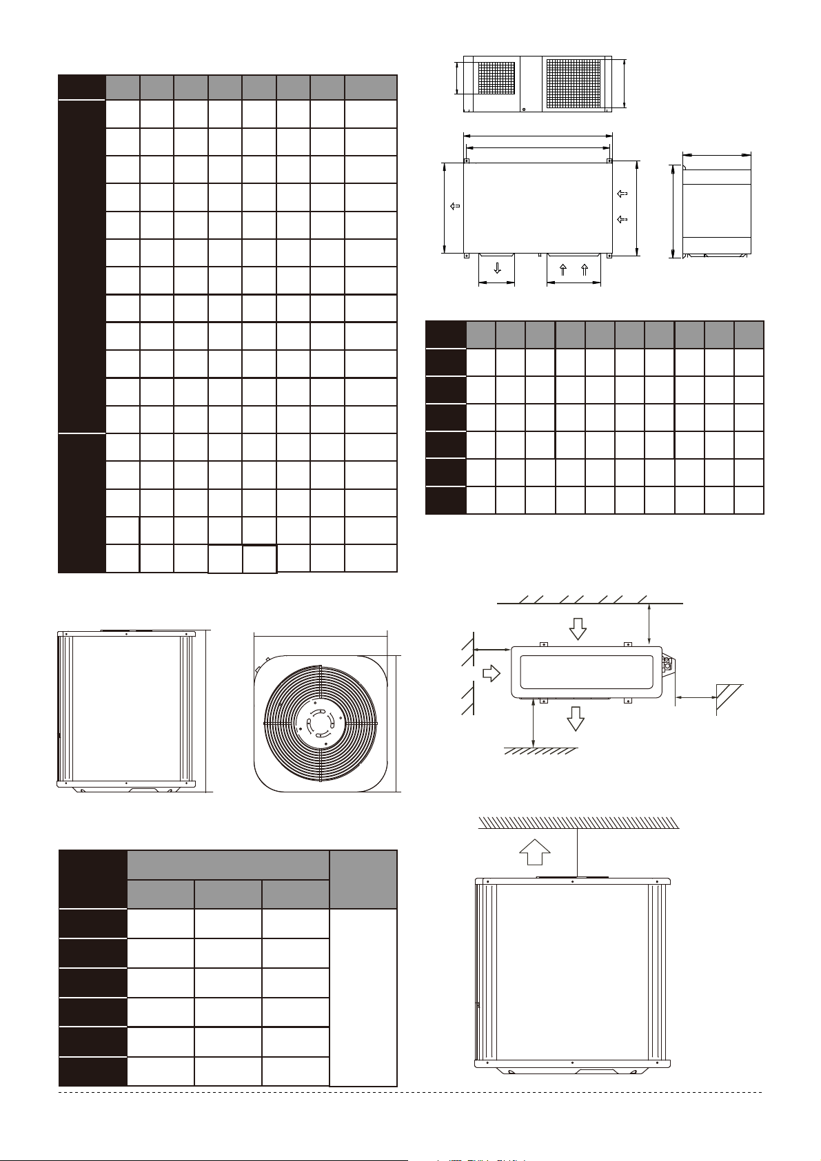
Fig.6-7
A
B
D
E
F
H
I
J
G
C
33.27 22.05 13.19 14.17 12.28 27.5612.6
Table 6-1 Unit: in
MODEL A B C D E H
REMARK
F
09~36
29.92 20.87 11.42 12.4 10.63 23.2311.22
31.89 21.61 12.8 13.78 12 21.9712.2
37.21 25.2 15.95 17.64 15.16 31.915.6
35.43 23.23 14.88 15.75 13 46.0613.78
38.98 24.57 14.41 15.59 13.39 3813.6
38.98
24.57
14.41
15.59
13.4 3813.6
23.23 14.88 15.75 13
46.0613.7835.43
42~60
30.71 21.58 10.5 11.81 9.5 21.269.84
Fig.6-2
33.27 13.78 14.8 13.19 27.5613.39
31.5 20.24
21.26
11.42 13.39 14.37 13.1112.4
Fig.6-2
30.32 19.17 11.73 12.68 10.24 21.8511.81
Fig.6-2
Fig.6-2
Fig.6-2
Fig.6-2
Fig.6-2
35.43 23.23 13.11 13.98 11.9 33.8612.4
Fig.6-2
Fig.6-2
Fig.6-3
Fig.6-2
Fig.6-3
Fig.6-2
Fig.6-3
Fig.6-3
24.96 15.91
17.64
14.5 53.915.4336.93
24.96 15.91
17.64
14.5 53.915.4336.93
37.24 26.5 15.87 17.91 15.95 31.916.54
Fig.6-2
Fig.6-3
24.96 15.91
17.64
15.04 52.4816.1437.4
Fig.6-5
Table 6-2
unit: in/mm
A
B
C
Fig.6-6
2. Vertical discharge type outdoor unit
BA C
24.92in/633 21.81in/554 21.81in/554
24.92in/633 21.81in/554 21.81in/554
29.88in/759
29.88in/759
21.81in/554 21.81in/554
24.92in/633 23.62in/600 23.62in/600
27.95in/710 27.95in/710
33.19in/843 27.95in/710 27.95in/710
MODEL
DIMENSIONS
36
48
60
36
24
18
Refore to
Fig.6-5
Fig.6-6
REMARK
Table 6-3
>30cm
/11.81in
>30cm
/11.81in
>200cm
/78.74in
>60cm
/23.62in
(Wall or obstacle)
Maintain channel
Air outlet
Air inlet
M
P
Air inlet
N
unit:in
3. Centrifugal fan type outdoor unit
6.3 Space of installation and maintenance
1.
Split type outdoor unit
2. Vertical discharge type outdoor unit
A
54.37
54.88
46.22
B
52.28
52.68
44.1
C
27.64
30.83
26.8
D
29.13
32.28
28.35
E
30.32
33.47
29.53
F
20.5
22.36
18.7
G
13.23
15.67
11.81
H
19.7
22.6
16.93
I
11.65
13.47
10.43
J
17.44
54.37 52.28 27.64 29.13 30.32 20.5 13.23 19.7 11.65 17.44
18.23
52.68 30.83 32.28 33.47 22.36 15.67 22.6 13.47 18.23
15.47
MODEL
30
36
48
60
18
46.22 44.1 26.8 28.35 29.53 18.7 11.81 16.93 10.43 15.47
24
54.88
12
installation manual
>120cm
/47.24in
Air Outlet
(Wall or obstacle)
Fig.6-9
Fig.6-8
For more details visit www.mrcool.com
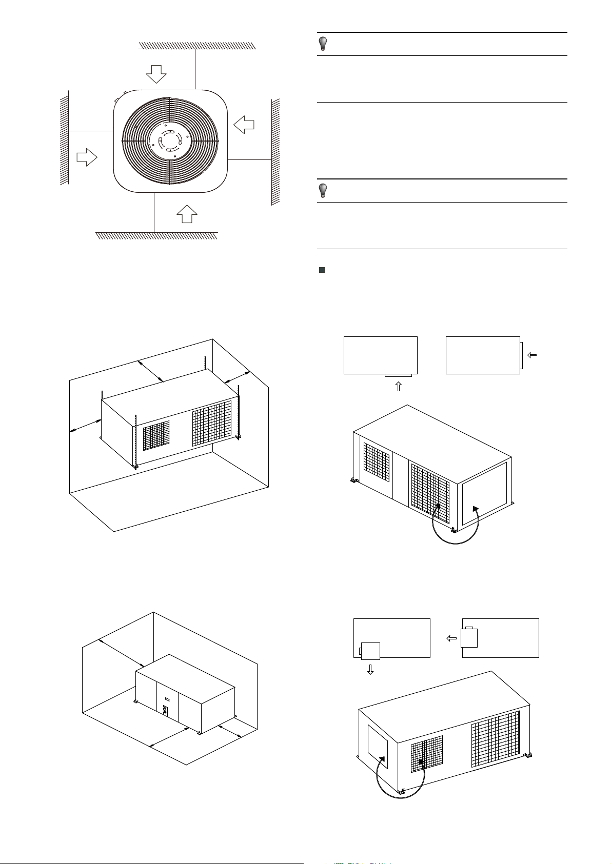
Fig.6-12
Fig.6-11
>30cm
/11.81in
>30cm
/11.81in
>30cm
/11.81in
>30cm
/11.81in
Air inlet
Air inlet
Air inlet
Air inlet
Fig.6-10
(Wall or obstacle)
≥400
/15.75in
≥300
/11.81in
≥300
/11.81in
a) In case that suspending in the ceiling
b)In case that installing on the floor
≥300
/11.81in
≥400
/15.75in
≥300
/11.81in
3. Centrifugal fan type outdoor unit
6.4 Available configuration for centrifugal fan
type outdoor unit
All the figures in this manual are for explanation
purpose only. They may be slightly different from the air
conditioner you purchased.The actual unit shall prevail.
NOTE
NOTE
Four different configuration are available for oudoor unit only
changing the panels and fan position.
Keep in mind that fan unit weight is aprox 30kg/1058oz ,the unit
as well as relevant equipment covered with the vinyl cover
during installation work.
To change air inlet is only necessary to interchange the
indicated panels position. Both panels
use screws to be fixed
to unit chassis.
To change air outlet is necessary to interchange panels too.
Fan outlet panel is attached to fan structure, which must be
mounted as follow.
Air inlet modification
Change Panel
Fig6-13
Fig.6-14
installation manual
13
For more details visit www.mrcool.com
6.5 Moving and installation
Fig.6-15
>60cm
/23.62in
Fix with bolt
Since the gravity center of the unit is not at its physical
center, so please be careful when lifting it with a sling.
Never hold the inlet of the outdoor unit to prevent it from
deforming.
Do not touch the fan with hands or other objects.
Do not lean it more than 45, and do not lay it sidelong.
Make concrete foundation accoding to the sepecif-ications of
the outdoor units.(Refer to Fig.6-15)
Fasten the feet of this unit with bolts firmly to prevent it from
collapsing in case of earthquake or strong wind.(Refer to
Fig.6-15)
1. Foundation could be on flat and is recommended be 100-300mm
/3.94-11.81in higher than ground level.
2.Install a drainage around foundation for smooth drain
3.When installing the outdoor unit fix the unit by anchor bolts of M10
4.When installing the unit on a roof or a veranda, drain water
sometimes turns to ice on the cold weather. Therefore, avoid
draining in an area that people often use because it is slippery.
Concrete Foundation
Fig.6-16
≥100
3.94in
100~300
3.94~11.81in
B
C
unit:in/mm
1. Suspend the unit as the drawing indicates.
2. Ensure that ceiling can resist the Outdoor unit weight indicated
in specification label plate.
Suspended unit
No Description
Outdoor Unit
Vibration-proof rubber
Anchor Bolt M10
Drainage (Wide 100/3.94in×Depth 150/5.9in)
Drainage
Mortar Hole (Φ100/3.94in×Depth 150/5.9in)
Sling Bolt
Suspension Bracket
Table 6-4
Table 6-5
Fig.6-17
MODEL B C
44.1in/1120 28.35in/720
52.67in/1338 32.28in/820
52.67in/1338 32.28in/820
52.67in/1338 32.28in/820
18~24
30
36
48~60
1
2
3
4
5
6
installation manual
14
Outfall
Fig.6-18
NOTE: Make sure 3-4 degree of angel is kept between the unit and
the floor when the unit is installed in the low temperauture
and humid environment.
Make sure the ice on the chassis of the outdoor unit can be
dealt with when the unit is installed in the low temperature
and humid enviroment.
The outdoor unit should be installed in mounting rack 30cm
/11.81in high.The enviroment temperature should be above
0°.
The machine must be installed indoor.
For more details visit www.mrcool.com
liquid tube(mm) R410A R22
Ø6.35
Ø9.53
Ø12.7
Ø15.9
Ø19.0
0.022kg/m×(L-5)
0.011kg/m×(L-5)
0.060kg/m×(L-5)
0.030kg/m×(L-5)
0.110kg/m×(L-5)
0.060kg/m×(L-5)
0.170kg/m×(L-5)
0.085kg/m×(L-5)
0.250kg/m×(L-5)
0.125kg/m×(L-5)
0.030kg/m×(L-5)
0.015kg/m×L
0.065kg/m×(L-5)
0.030kg/m×L
0.115kg/m×(L-5)
0.060kg/m×L
0.190kg/m×(L-5)
0.095kg/m×L
0.290kg/m×(L-5)
0.145kg/m×L
orifice in the indoorunit
orifice in the outdoorunit
orifice in the outdoorunit
orifice in the outdoorunit
orifice in the outdoorunit
orifice in the outdoorunit
orifice in the indoorunit
orifice in the indoorunit
orifice in the indoorunit
orifice in the indoorunit
Model
12K
18K-24K
30K-42K
12K
18K-24K
30K-60K
48K-60K
12K
18K-24K
30K
48K-60K
36K
50Hz T1 condition/R22
Split type air conditioner
50Hz Vertical discharge air conditioner
/60Hz T1 condition/R22 Split type air
conditioner and Vertical discharge air
conditioner
The type of models
R410A inverter Split type air
conditioner and and Centrifugal
fan outdoor unit
164.04ft/50
164.04ft/50
98.42ft/30
49.21ft/15
164.04ft/50
98.42ft/30
49.21ft/15
98.42ft/30
98.42ft/30
82.02ft/25
32.8ft/10
82.02ft/25
R410A Split type air conditioner
and and Centrifugal fan outdoor
unit
50Hz/60Hz T3 condition
(outdoor unit down)
50Hz/60Hz T3 condition
(outdoor unit up)
the unit with quick joint
12K
48K-60K
18K-30K
36K
18K-24K
42K-60K
30K
36K
18K-24K
12K-18K
48K-60K
42K
30K
36K
164.04ft/50
82.02ft/25
49.21ft/15
98.42ft/30
164.04ft/50
98.42ft/30
82.02ft/25
98.42ft/30
82.02ft/25
164.04ft/50
98.42ft /30
98.42ft/30
164.04ft/50
49.21ft/15
114.83ft/35
16.4ft/5
16.4ft/5
82.02ft/25
65.62ft/20
98.42ft/30
82.02ft/25
49.21ft/15
26.25ft/8
65.62ft/20
82.02ft/25
49.21ft/15
32.8ft/10
65.62ft/20
65.62ft/20
82.02ft/25
39.37ft/12
16.4ft/5
49.21ft/15
82.02ft/25
32.8ft/10
26.25ft/8
65.62ft/20
32.8ft/10
26.25ft/8
65.62ft/20
refrigerant pipe
The length of
height drop
The max
NOTE:The number of bends is up to the length of the max
height drop.Usually for each 32.8ft/10m need a bend.
NOTE:the table above refer to the liquid tube.
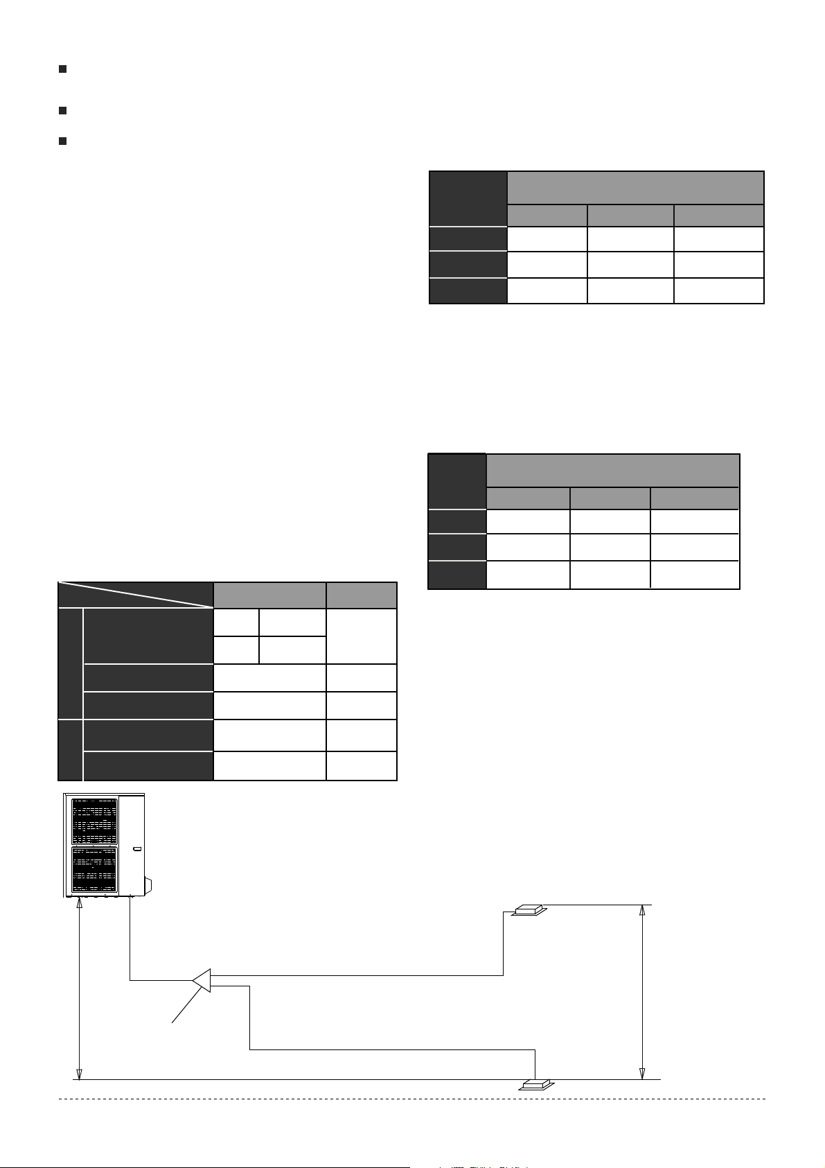
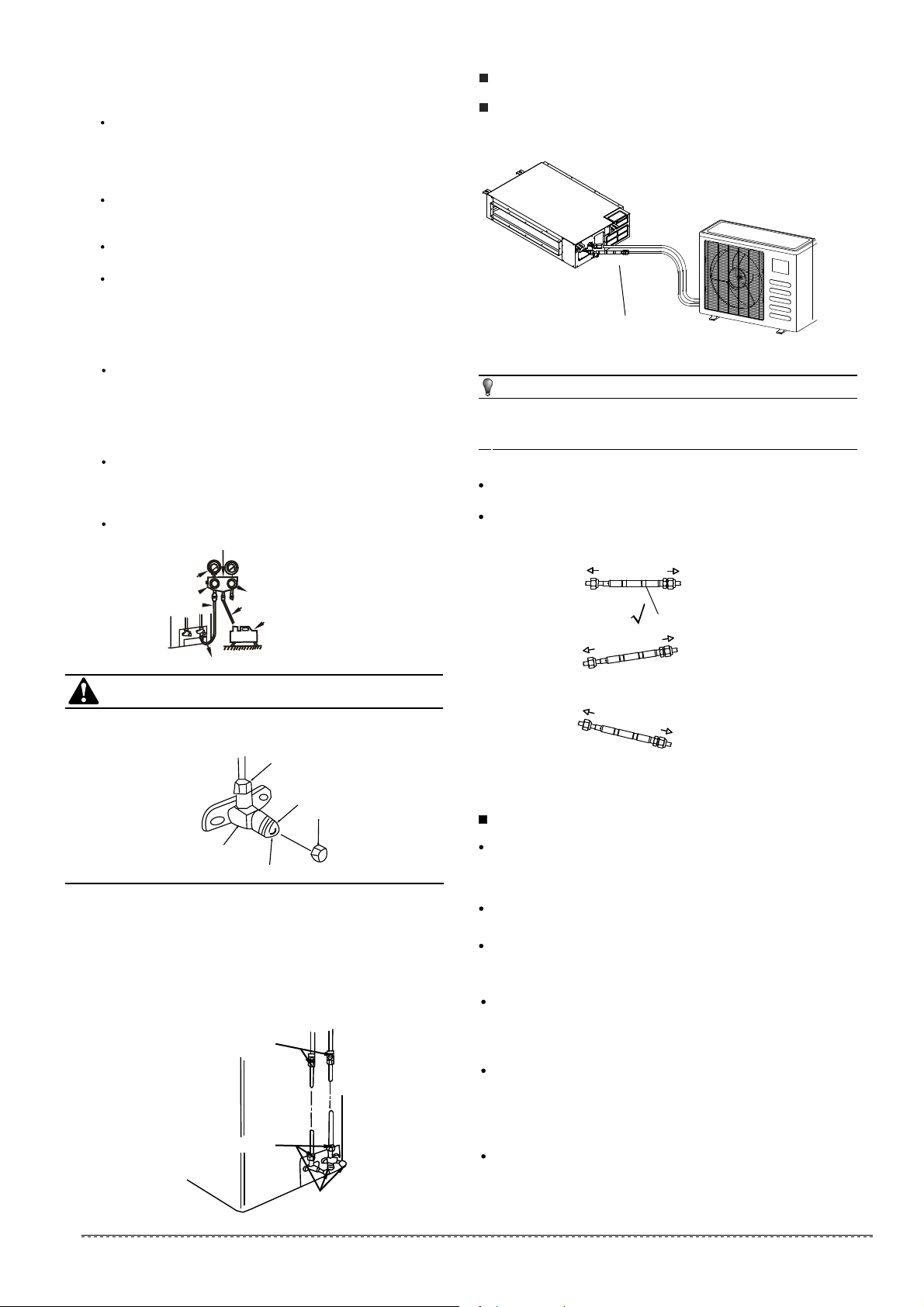
7. INSTALL THE CONNECTING PIPE
Before installation make sure the height difference, the length
of refrigerant pipe, and the number of the bends between the
indoor unit and outdoor unit meet the following requirements:
Table 7-1 unit: ft/m
The outdoor unit is charged with rating refrigerant amount in
the factory.Additional charge refers to the table below:
Table 7-2
7.2 The Procedure of Connecting Pipes
Connect the indoor unit first, then the outdoor unit.
Bend the tubing in proper way. Do not twist the pipe.
Bend the pipe with thumb
min-radius 100mm/3.94in
Fig.7-1
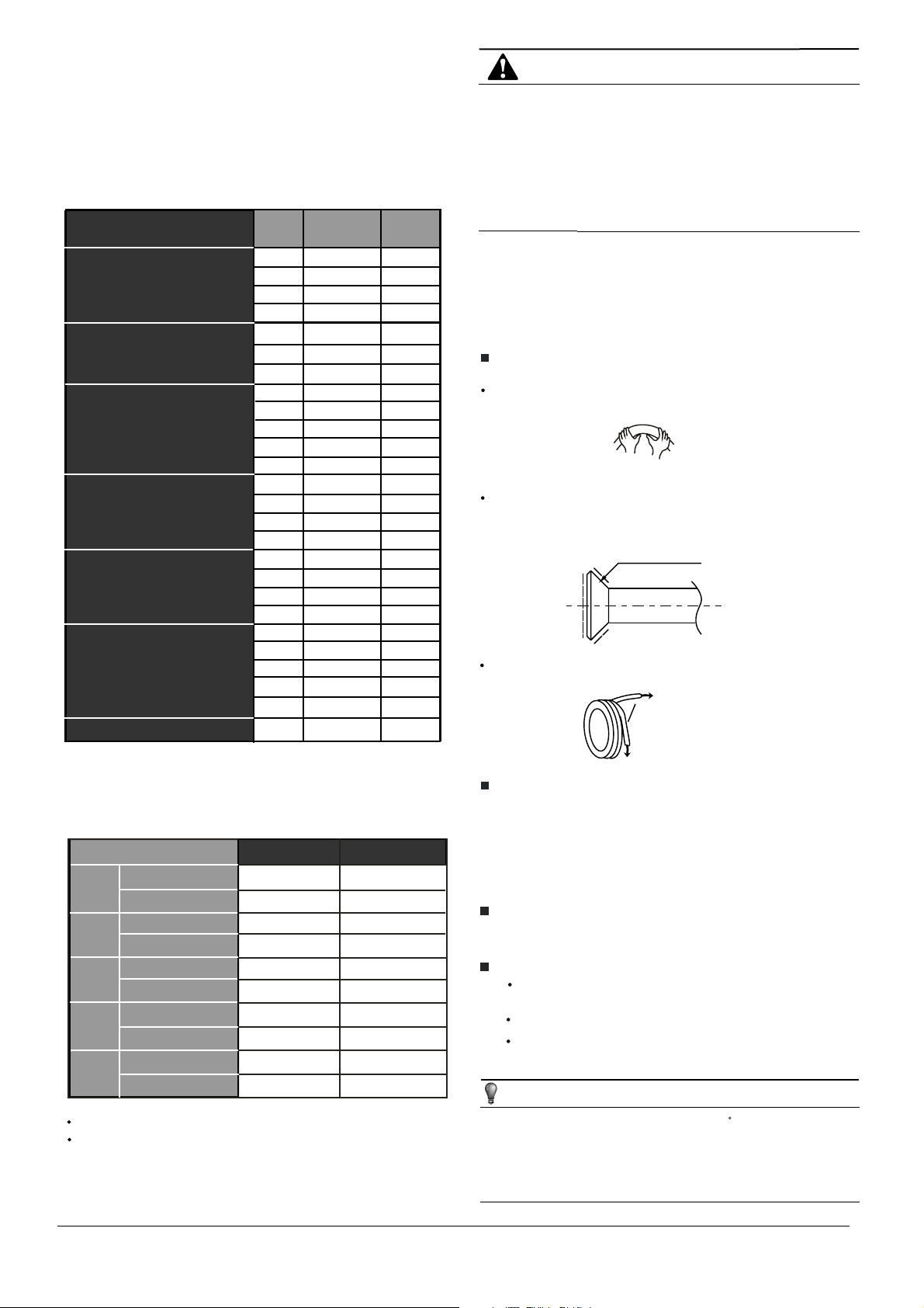
Put some refrigerant oil on the surfaces of the flare pipe
and the joint nuts then wrench it for 3~4 rounds with
hands before fasten the flare nuts.(Refer to chart 16)
Use frozen oil
Fig.7-2
Measure the required length of the connecting
pipe, then make it by the following way.
1
All field piping must be provided by a licensed
refrigeration technician and must comply with the
relevant local and national codes.
Prevent let air, dust, or other impurities enter in the pipe
system during installation.
Insulation pipe shall be used to the gas piping and the
liquid piping. Otherwise, the condensate may happen.
CAUTION
NOTE
The service valves of the outdoor unit should be completely
closed(as original status).Every time to connect,first to loosen
nuts, then connect the flare pipes within 5 minutes. If the nuts
have been loosened for a long time, dusts and other impurities
may enter the pipe system and may cause malfunction.So
please expel the air out of the pipe with refrigerant before
connection.
Expel the air(refer to the “8.1”)after connecting the refrigerant
pipe with the indoor unit and the outdoor unit.
Then fasten the nuts at the service valves.
Bend the connecting pipe of small wall thickness.
Cut out a proper concave at the bending part of the
insulating pipe.
Then expose the pipe(cover it with tapes after bending).
To prevent twist of deforming, please bend the pipe at a
proper radius.
Fig.7-3
Make the ends straight
The bending angle should not exceed 90 .
Bending position is preferably in the middle of the bendable pipe.
Do not bend the pipe more than three times.
Be sure to use the same insulating materials when you buy the
brass pipe. (More than 0.35in/9mm thick)
Be sure to use two wrenches simultaneously when you
connect or disconnect the pipes.
7.1 Preparation and Caution
15
installation manual
For more details visit www.mrcool.com
8.1 Length and drop height permitted of the
refrigerant piping
8. REFRIGERANT PIPE(the unit with the
twins function)
Note: Reduced length of the branching tube is the 0.5m/1.64ft
of the equivalent length of the pipe.
Table.8-1
Permitted value
Piping
Total pipe length (Actual)
Indoor unit to indoor unit drop height
(farthest from the line
pipe branch)
(farthest from the line
pipe branch)
Pipe length
Drop height
Indoor unit-outdoor unit
drop height
98.42ft/30m
18K+18K
24K+24K/
30K+30K
164.04ft/50m
49.21ft/15m
32.8ft/10m
65.8ft/20m
1.64ft/0.5m
L+L1+L2
L1,L2
L1-L2
H1
H2
Fig.8-1
A
L
L1
L2
Outdoor unit
The line branch pipe
Drop height between indoor
unit and outdoor unit H≤20m/65.8ft
Indoor unit to intdoor unit
drop height H≤0.5m/1.64ft
Indoor unit
Note: All used branch pipe must be produced by Midea,
otherweise it causes malfunction. The indoor units should
be installed equivalently at the both side of the U type branch
pipe.
8.3 Size of joint pipes for outdoor unit
Model
Gas side Liquid side
Φ15.9/0.626in
Φ15.9/0.626in
Φ15.9/0.626in
Φ9.5/0.375in
Φ9.5/0.375in
Φ9.5/0.375in
the size of main pipe(mm)
36K
48K
60K
Size of joint pipes for 410A outdoor unitTable.8-3
Base on the following tables, select the diameters of the
outdoor unit connective pipes. In case of the main
accessory pipe large than the main pipe, take the large one
for the selection.
The 1st
branching pipe
8.2 Size of joint pipes for indoor unit
Gas side
Capacity of
indoor unit
(A)
Size of main pipe(mm)
Liquid side
Φ12.7/0.5in
Φ15.9/0.626in
Φ15.9/0.626in
Φ6.35/0.25in
Φ9.5/0.375in
Φ9.5/0.375in
18K
24K
30K
Size of joint pipes for 410A indoor unit
Table.8-2
CE-FQZHN-01C
CE-FQZHN-01C
CE-FQZHN-01C
CE-FQZHN-01C
CE-FQZHN-01C
CE-FQZHN-01C
Available
branching pipe
2. Place The Pipe
Drill a hole in the wall (suitable just for the size of the wall
sleeve), then set on the fittings such as the wall sleeve and its
cover.
Bind the connecting pipe and the cables together tightly with
binding tapes.
Pass the bound connecting pipe through the wall sleeve from
outside. Make sure of the pipe allocation not to damage the
copper tubes.
3
5
6
7
4
Connect the pipes.
Expel the air with a vacuum pump or refrigerant.
Open the service valves of the outdoor unit .
Check the refrigerant leakage. Check all the joints
with the leak detector or soap water.
Cover the joints of the connecting pipe with the
insulation foam, and bind them well with the tapes to
prevent potential leakage.
16
installation manual
For more details visit www.mrcool.com
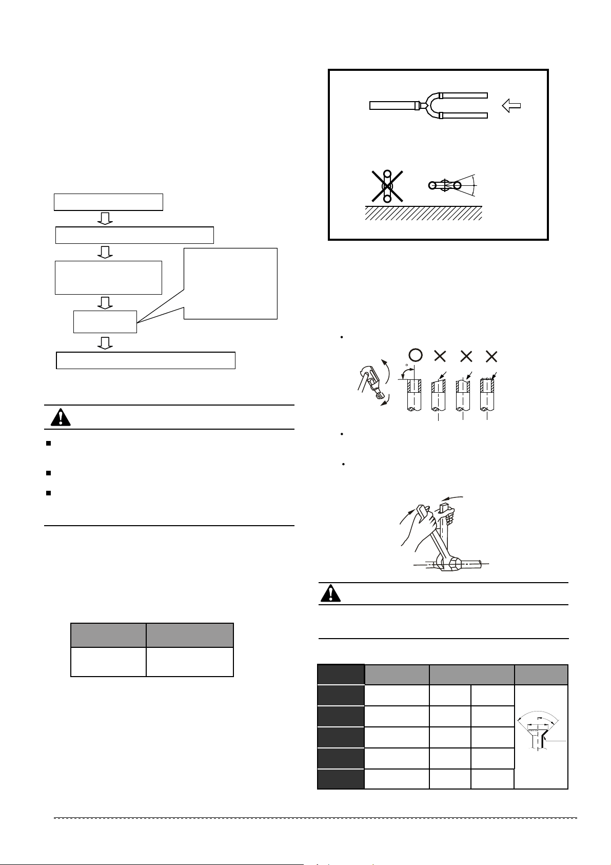
Fig.8-2
10°
10°
A
Fig.8-3
The branching pipe must be installed horizontally, error angle
of it should not large than 10°. Otherwise, malfunction will be
caused.
CorrectWrong
U-shaped branching pipe
Horizontal surface
A direction view
1)
Use the vacuum pump which vacuum level lower than
-0.1MPa and the air discharge capacity above 40L/min.
The outdoor unit is not necessary to vacuum, don’t open the
outdoor unit gas and liquid pipe shut-off valves.
Make sure the vacuum pump could result as -0.1MPa or
below after 2 hrs or above operation. If the pump operated 3
hrs or above could not achieve to -0.1MPa or below, please
check whether water mix or gas leak inside of the pipe.
8.4 Vacuum with vacuum pump
1)
2)
3)
CAUTION
8.5 Refrigerant amount to be added
Calculate the added refrigerant according to the diameter and
the length of the liquid side pipe of the outdoor/indoor unit
connection. The refrigerant is R410A.
Pipe size on
liquid side
Refrigerant to
be Added per meter
Φ6.35/0.25in
Φ9.52/0.375in
0.015kg/0.033lb
0.030kg/0.066lb
Table.8-4
Don’t mix up the different refrigerants or abuse the tools and
measurements which directly contact with refrigerants.
Don’t adopt refrigerant gas for air vacuuming.
If vacuum level could not get to -0.1MPa, please check whether
resulted by leakage and confirm the leakage site.If no leakage,
please operate the vacuum pump again 1 or 2 hrs.
Connect with vacuum pump
Perform the pump (last for 2 hrs or above)
When get the vacuum level
-0.1MPa, the pump should
keep running for 20-60 mins
Shut down the
vaccun pump
Place the vaccum state unused (1 hrs or above)
1. Close-off the valve of
vacuum meter.
2. Cut off the connection
between pressure meter
and vacuum pump.
3. Close the vacuum
pump.
CAUTION
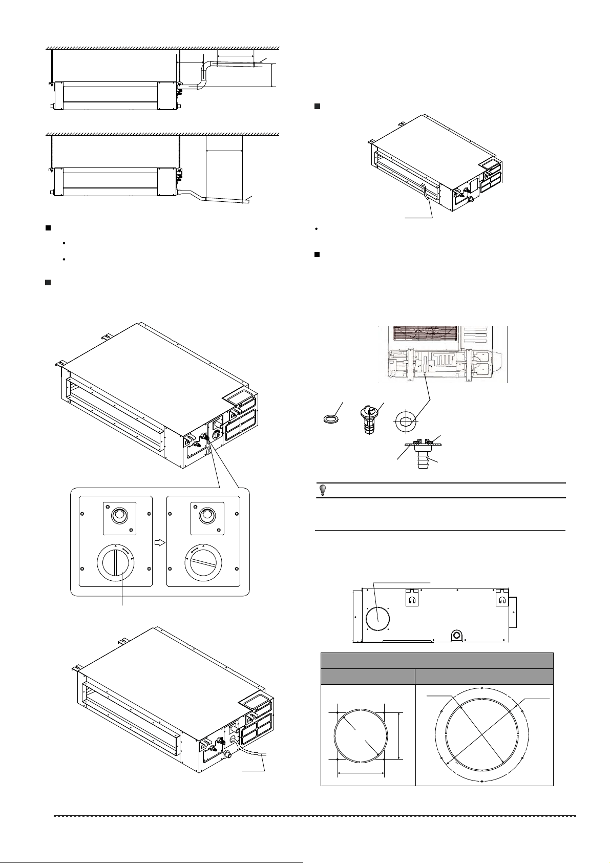
Flaring
1
Cut a pipe with a pipe cutter. (Refer to Fig.9-1)
Table 9-1
Insert a flare nut into a pipe and flare the pipe.
Fig.9-1
(mm)
Ø6.35/0.25in 0.327in/8.3 0.343in/8.7
Ø9.52/0.375in 0.472in/12.0 0.488in/12.4
Ø12.7/0.5in 0.606in/15.4 0.622in/15.8
Ø15.9/0.626in
Ø19.1/0.725in
0.732in/18.6 0.748in/19.0
0.902in/22.9 0.917in/23.3
R0.4~0.8
45
°
±
2
90
°
±
4
A
min max
Pipe gauge
Tightening torque
Flare dimensin A
Flare shape
97.2~118.6 N.m
(990~1210 kgf.cm)
(630~770 kgf.cm)
61.8~75.4 N.m
49.5~60.3 N.m
(504~616 kgf.cm)
32.7~39.9 N.m
(333~407 kgf.cm)
14.2~17.2 N.m
(144~176 kgf.cm)
9.1 Expel The Air
Fasten the nut
2
Put the connecting pipes at the proper position,
wrench the nuts with hands then fasten it with
two wrenches simultaneously. (Refer to Fig.9-2)
Fig.9-2
Too large torque will harm the bellmouthing and too small will
cause leakage. Please determine the torque according to
Table 9-1.
9. REFRIGERANT PIPE CONNECTION
90
Lean crude burr
17
installation manual
For more details visit www.mrcool.com
CAUTION
When the pumping has finished, close the Lo-lever of the
manifold valve completely and turn off the vacuum pump.
When you have pumped for over 15 minutes, please
confirm that the indicator of multimeter is on -1.0X10
-5
Pa
(-76cmHg)
Loosen and remove the nuts of service valves A and B to
open service valve A andB completely, then fasten nuts.
Disassemble the charge hose of service valve A, and
fasten the nut.
Both service valves should be open before test operation.
Each air conditioner has two service valves of different
sizes.(Refer to Fig.8-4)
Flare nut
Stopper
Cap
Valve body
Valve stern
9.2 Check the Leakage
Check all the joints with the leak detector or soap water. (Refer
Fig.9-5 as a reference illustration)
in the chart
A......Lo-stop valve
B......Hi-stop valve
C,D..Joints of the connecting pipe to the indoor unit.
B A
D
C
Check-point of indoor unit
Check-point of outdoor unit
-76 cmHg
Lo-lever
Hi-lever
Charge hose
Charge hose
Vacuum pump
Lo-lever
Manifold valve
Multi-meter
Pressure meter
Fig.9-3
Fig.9-4
9.3 Insulation
Be sure to completely insulate all the exposed parts of the flare
pipes.
Incomplete insulation may cause condensate.
Fig.9-5
10. CONNECTIVE DIAGRAM
Orifice
Fig. 10-1
Fig. 10-2
For ensuring throttled efficiency, Please mount the Orifice as
horizontally as possible; and anti-shock rubber should be
wrapped at external of the Orifice for denoise.
NOTE
Please purchase the fittings according to the requirements in
the manual strictly.
Refer the diagram when installing.
Mark the data plate with the Orifice installed.(for some models)
Liquid side
Liquid side
Indoor
Indoor
Outdoor
Outdoor
X
Liquid side
Indoor
Outdoor
X
NOTE:the orifice should be horizontally installed.
Liquid side
Gas side
Expel the air with a vacuum pump(Refer to Fig.9-3)
3
(Please refer to its manual for the way of using manifold
valve)
18
installation manual
11. CONNECT THE DRAIN PIPE
Install the drainpipe of the indoor unit
Use a polyethylene tube as the drainpipe (out-dia. 1.14-1.22in
/29-31mm, in-dia. 0.984in/25mm). It could be bought from the
local market.
When extending drainpipe,tighten the connector with
water-proof tape to prevent it leakage.
Please lean the drainpipe down toward outdoor (outlet-side)
at a degree of over 1/ 50 to avoid water flowing back. And
please avoid any bulge.
Do not drag the drainpipe violently. Meanwhile, one
supportpoint should be set every 3.28~4.92ft/1~1.5m to
prevent the drainpipe from yielding. Or tie the drainpipe with
the connecting pipe to fix it.
If the outlet of the drainpipe is higher than the body's pump
joint, the pipe should be arranged as vertically as possible.
And the lift distance must be less than 21.65in/550mm,
otherwise the water can not be lifted completely and cause
overflow.(Only available for the unit with pump.)
The end of the drainpipe should be over 1.969in/50mm higher
than the ground , and do not immerse it in water. If you
discharge the water directly into sewage, be sure to make a
U-form aquaseal by bending the pipe up to prevent the smelly
gas entering the house through the drain pipe.
Loosen and remove the nuts of service valves A and B,
and connect the charge hose of the manifold valve with
the maintenance terminator of service valve A. (Be sure
that service valves A and B are both closed)
Connect the joint of the charge hose with the vacuum
pump.
Open the Lo-lever of the manifold valve completely.
Turn on the vacuum pump. At the beginning of pumping,
loosen the nut of service valve B a little to check whether
the air comes in (the sound of the pump changes, and
the indicator of compound meter turns below zero). Then
fasten the nut.
For more details visit www.mrcool.com
The drain pipe installation for the unit with pump.
The drain pipe installation for the unit without pump.
Lean over 1/50
Fig.11-1
Fig.11-2
Lean over 1/50
Drainage testDrainage test
Check whether the drainpipe is unhindered.
New built house should have this test done before paving
the ceiling.
The unit with pump.
Remove the test cover, and stow about 2000ml water to the
water pan.
1
NOTE
Fig.11-5
Install the drain joint of the outdoor unit
(For Heat Pump Models)
Fit the seal into the drain joint, then insert the drain joint into the
base pan hole of outdoor, rotate 90° to securely assemble them.
Connect the drain joint with an extension drain hose (Locally
purchased)to avoid condensate draining off the outdoor unit
during the heating mode.
Seal
Base pan hole
Drain joint
Seal
Base pan
Drain
joint
Fig.11-6
All the figures in this manual are for explanation purpose only.
They may be slightly different from the air conditioner you
purchased.The actual unit shall prevail.
The unit without pump.
Stow 2000ml water to the water pan through the stow
tube,check whether the drainpipe is unhindered.
Stow tube
Fig.12-1
12. FRESH AIR DUCT INSTALLATION
Dimension :
Duct joint for fresh air
3.15in/80mm
3.15in/80mm
Ø90mm/3.54in
Ø125mm/4.92in
Ø160mm/6.3in
MODLE
12-24 30-60
Operate the air conditioner in "COOLING" mode. The sound of
the drain pump shall be heard. Check whether the water is
discharged well (1 min lag is possible, according to the length of
the drain pipe), and check whether the water leaks from the
joints.
2
Power off the air conditioner and recover the cap.
3
Test cap
Fig.11-3
Fig.11-4
C
L
O
S
E
D
O
P
E
N
C
L
O
S
E
D
O
P
E
N
Stow tube
19
installation manual
3.28-4.92ft/1-1.5m
<7.87in/200mm
<21.65in/550mm
3.28-4.92ft/1-1.5m
For more details visit www.mrcool.com
14. WIRING
The appliance shall be installed in accordance with
national wiring regulations.
The air conditioner should use separate power supply
with rated voltage.
The external power supply to the air conditioner should
be grounded, which is linked to the ground wiring of the
indoor and outdoor unit.
The wiring work should be done by qualified persons
according to wiring diagram.
A circuit breaker and a residual current device (RCD) with
above 10mA rating shall be installed in the power circuit
according to the national rule.
Be sure to locate the power wiring and the signal wring
well to avoid cross-disturbance.
Do not turn on the power until you have confirmed
proper wiring.
The power cord type is H07RN-F.
The power connection for the air conditioner has to be
done at the main power distribution. The distribution has
to be of a low impedance, normally the required
impedance reaches at a 32 A fusing point.
No other equipment has to be connected with this power
line.
For detailed installation acceptance please refer to your
power supplier, if restrictions do apply for products like
washing machines, air conditioners or electrical ovens.
For power details of the air conditioner refer to the rating
nameplate of the product.
For any question contact your local dealer.
1
2
4
3
5
Refer to EMC Directive 2004/108/EC
To prevent flicker impressions during the start of the
compressor,following installation conditions do apply.
NOTE
Table 13-2
Fig.12-3
Pump maintainance:
Screw off four screws from drain pump.
Plug off pump power supply and water level switch cable.
Take off pump.
1.
2.
3.
Pump
Table 13-1
13. CONTROL(ONLY FOR INVERTER UNITS)
Horsepower code setting
13.1
The capacity of the system and the network address of
the air-conditioner can be set by the switches on the
indoor Main Control Board.
Before setting, turn off the power. After setting, restart
the unit.
Setting is not allowed when the unit is power on.
The capacity of the indoor unit has been set in the
factory according to the below table.
Horsepowe r code
ENC1
PO WER_S
0
1
2
3
4
5
6
7
8
9
A
B
C
D
E
F
ENC1
Note: The capacity
has been set in the
factory , anyone
can’t adjust it
except the qualified
person.
Toggle switch
Code
Capacity(kw)
4
5.3
5.6
5 7.1
7 9.0
8 10.5
9
14.0
16.0
Every air-conditioner in network has only one network address
to distinguish each other. Address code of air-conditioner in
LAN is set by code switches S1 & S2 on the Main Control Board
of the indoor unit, and the set range is 0-63.
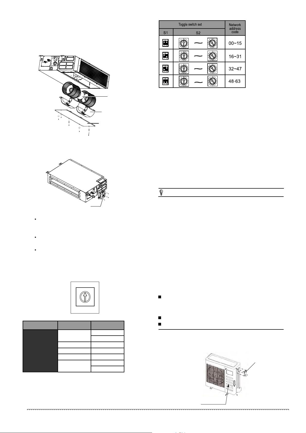
13.2 Network address set
Disassemble the cover.(If there isn't a cover on the outdoor
unit, disassemble the screw from the maintenance board, and
pull it in the direction of the arrow to remove the protection
board.) (Refer to Fig.14-1)
Connect the cables to the terminals correspondingly.
Re-install the cover or the protection board.
Connect the cable
14.1
The Specification of Power
14.2
(Refer to Table14-1~14-8)
Fig.13-1
Protection board
Wiring figure
14.3
(Refer to Fig.14-2~Fig.14-5)
1.split type outdoor unit
Cover
20
installation manual
Fig.12-2
12.1Motor and drain pump maintenance
Motor maintain:
Take off the ventilated panel.
Take off the blower housing.
Take off the motor.
1.
2.
3.
(Take rear ventilated as example)
Motor
Blower housing
Ventilated panel
For more details visit www.mrcool.com
21
installation manual
Test operation
3
Set the air conditioner in cooling mode with the remote
controller, and check the following points. If there is any
malfunction, please resolve it according to the chapter
"Troubleshooting" in the "Owner's Manual".
1) The indoor unit
a. Whether the buttons on the remote controller works
well.
b. Whether the air flow louver moves normally.
c. Whether the room temperature is adjusted suitable.
d. Whether the indicator lights normally.
e. Whether the temporary switch on the unit works well.
f. Whether the drainage is normal.
g. Whether there is abnormal vibration or noise during
operation.
h. Whether the air conditioner works well in heating
mode(heat pump model).
2) The outdoor unit
a. Whether there is abnormal vibration and noise during
operation.
b. Whether the exhaust air, noise, or condensate influence
your neighborhood.
c. Whether there is any refrigerant leakage during
operation.
3 minutes delay is normal when restarting the unit for
compressor protection.
CAUTION
15. TEST OPERATION
The test operation must be carried out after the entire
installation.
Please confirm the following points before the test operation:
2
1
The indoor unit and outdoor unit are installed properly.
Tubing and wiring are correctly completed.
The refrigerant pipe system is leakage-checked.
The drainage is unimpeded.
The heating insulation works well.
The ground wiring is connected correctly.
The length of the tubing and additional charge amount
have been recorded.
The power voltage matches rated voltage of the air
conditioner.
There is no obstacle at the outlet and inlet of the outdoor
and indoor units.
The gas-side and liquid-side service valves are both
completely open.
The air conditioner is pre-heated by turning on the power.
All the figures in this manual are for explanation purpose only.
They may be slightly different from the air conditioner you
purchased(depend on model).The actual unit shall prevail.
NOTE
Fig.14-2
Protection Board
2.Centrifugal fan outdoor unit
For more details visit www.mrcool.com
22
installation manual
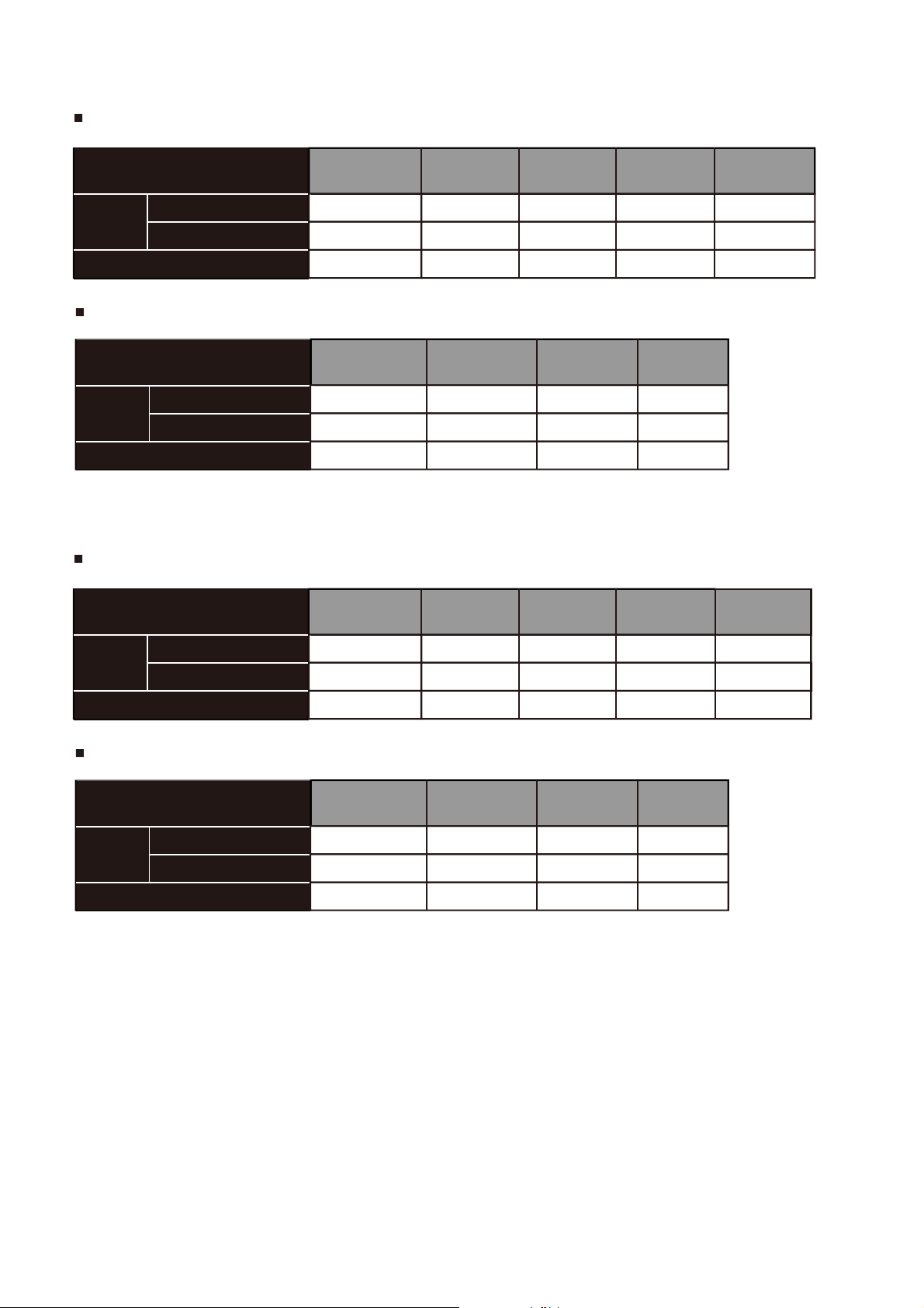
Table 14-1
Table 14-2
The Specification of Power(indoor power supply)
The Specification of Power(outdoor power supply)
20/16 40/25 50/30 60/45 60/50
40/30 60/40 70/55 70/60
MODEL
POWER
CIRCUIT BREAKER/FUSE(A)
PHASE
FREQUENCY AND VOLT
18 24 6030~36 42~48
208-240 V 208-2 40V
1Phase 1Phase
208-2 40V
1Phase
208-2 40V
1Phase
208-2 40V
1Phase
MODEL
POWER
CIRCUIT BREAKER/FUSE(A)
PHASE
FREQUENCY AND VOLT
30~36 30~36
42~60 42~60
380-420V
25/20 25/20 40/25 45/35
208-2 40V
3Phase
380-420V
3Phase 3Phase
208-2 40V
3Phase
Table 14-3
Table 14-4
MODEL
POWER
CIRCUIT BREAKER/FUSE(A)
PHASE
FREQUENCY AND VOLT
24 6030~36 42~48
208-2 40V
1Phase
20/16
12~18
208-2 40V
1Phase
208-2 40V
1Phase
208-2 40V
1Phase
208-2 40V
1Phase
MODEL
POWER
CIRCUIT BREAKER/FUSE(A)
PHASE
FREQUENCY AND VOLT
30~36 30~36
42~60 42~60
380-420V
25/20 25/20 40/25 45/35
208-2 40V
3Phase
380-420V
3Phase 3Phase
208-2 40V
3Phase
For more details visit www.mrcool.com
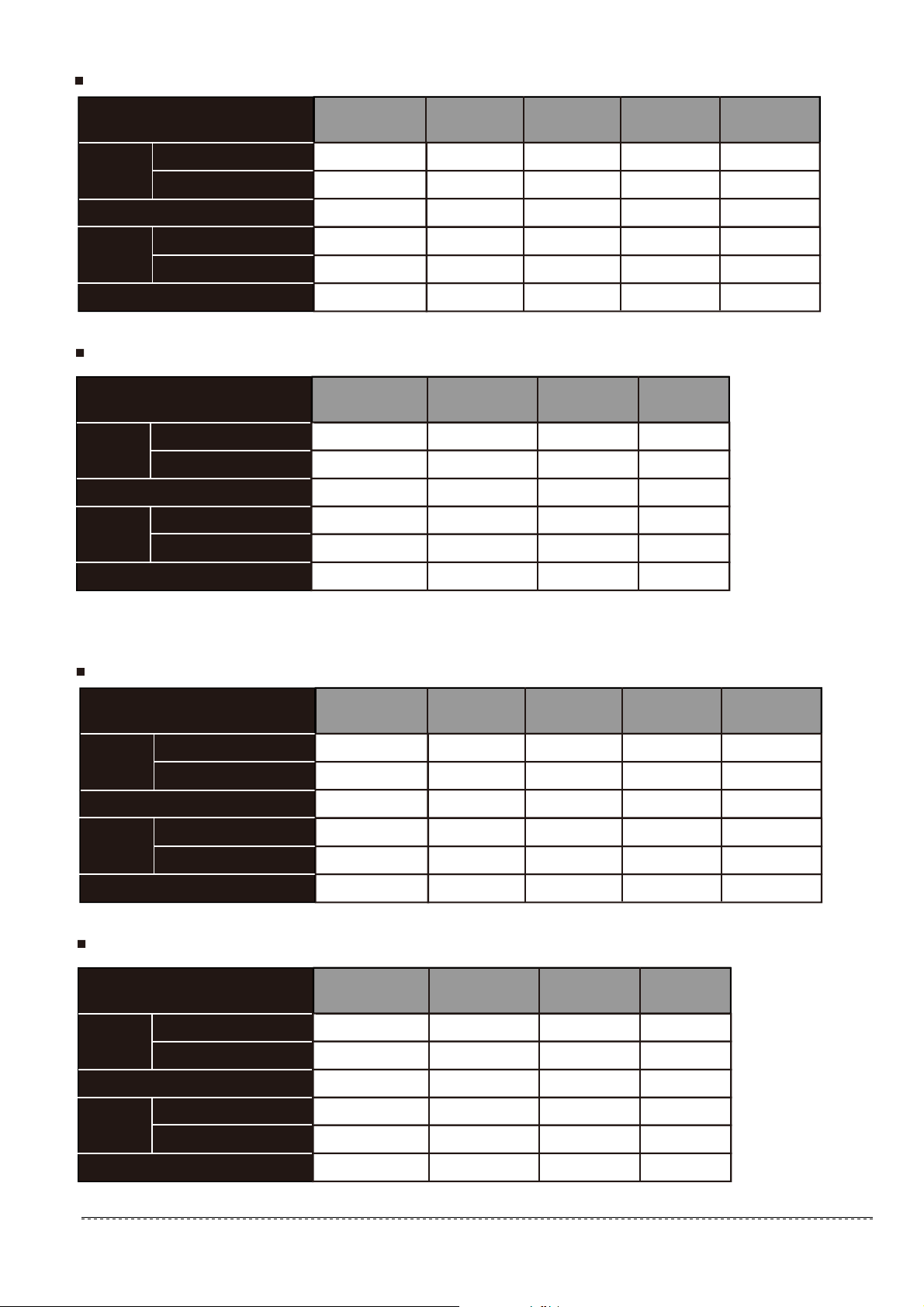
23
installation manual
The Specification of Power(independence power supply)
The Specification of Power for the invert type air conditioner(independence power supply)
20/16 40/25 50/30 60/45 60/50
208-240 V 208-2 40V
1Phase 1Phase
208-2 40V
1Phase
208-2 40V
1Phase
208-2 40V
1Phase
MODEL
POWER
(indoor)
POWER
(outdoor)
POWER
(indoor)
POWER
(outdoor)
CIRCUIT BREAKER/FUSE(A)
CIRCUIT BREAKER/FUSE(A)
PHASE
FREQUENCY AND VOLT
PHASE
FREQUENCY AND VOLT
18 24 6030~36 42~48
208-240 V 208-2 40V
1Phase 1Phase
208-2 40V
1Phase
208-2 40V
1Phase
208-2 40V
1Phase
20/16 20/16 20/16 20/16 20/16
208-2 40V
1Phase
208-2 40V
1Phase
208-2 40V
1Phase
208-2 40V
1Phase
20/16 20/16 20/16 20/16
MODEL
CIRCUIT BREAKER/FUSE(A)
CIRCUIT BREAKER/FUSE(A)
PHASE
FREQUENCY AND VOLT
30~36 30~36
42~60 42~60
380-420V
25/20 25/20 40/25 45/35
208-2 40V
3Phase
380-420V
3Phase 3Phase
208-2 40V
3Phase
Table 14-5
Table 14-6
PHASE
FREQUENCY AND VOLT
POWER
(indoor)
POWER
(outdoor)
30/20 30/20 40/30 40/35 50/40
208-240 V 208-2 40V
1Phase 1Phase
208-2 40V
1Phase
208-2 40V
1Phase
208-2 40V
1Phase
MODEL
POWER
(indoor)
POWER
(outdoor)
POWER
(indoor)
POWER
(outdoor)
CIRCUIT BREAKER/FUSE(A)
CIRCUIT BREAKER/FUSE(A)
PHASE
FREQUENCY AND VOLT
PHASE
FREQUENCY AND VOLT
18 24 6030~36 42~48
220-240 V 220-2 40V
1Phase 1Phase
220-2 40V
1Phase
220-2 40V
1Phase
220-2 40V
1Phase
15/10 15/10 15/10 15/10 15/10
220-2 40V
1Phase
220-2 40V
1Phase
220-2 40V
1Phase
220-2 40V
1Phase
15/10 15/10 15/10 15/10
MODEL
CIRCUIT BREAKER/FUSE(A)
CIRCUIT BREAKER/FUSE(A)
PHASE
FREQUENCY AND VOLT
30~36 30~36
42~60 42~60
380-420V
30/20 30/25 50/40 50/40
208-2 40V
3Phase
380-420V
3Phase 3Phase
208-2 40V
3Phase
Table 14-7
Table 14-8
PHASE
FREQUENCY AND VOLT
POWER
(indoor)
POWER
(outdoor)
For more details visit www.mrcool.com

The power supply is included in the power supply above mentioned can be applied to the table.
Before obtaining access to terminals, all supply circuits must be disconnected.
CAUTION
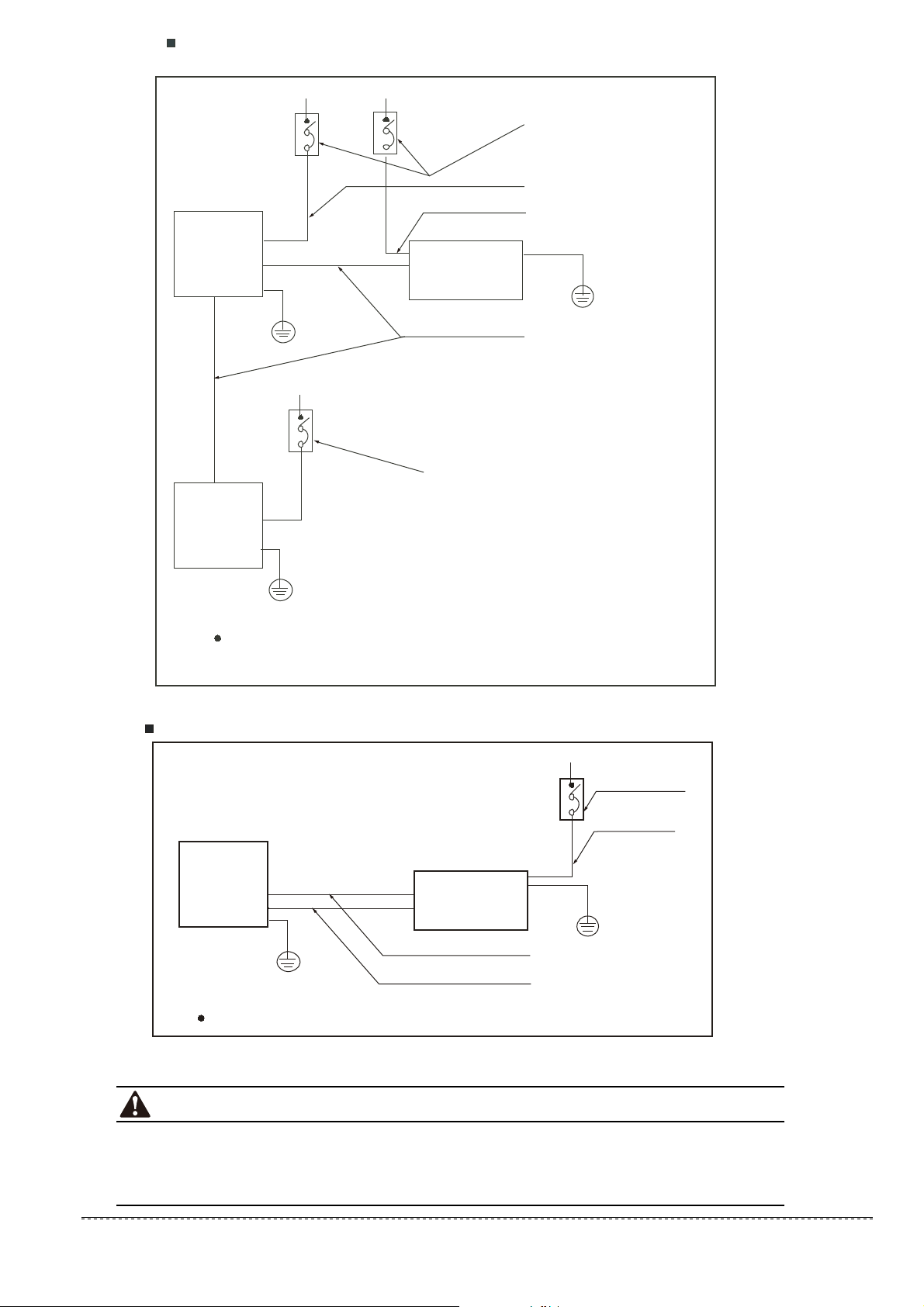
Wiring figure
Fig.14-3
Fig.14-4
Ground wiring
Ground wiring
Power supply
Switch/Fuse
(Available locally)
Power wiring (indoor)
Power linking wiring (Outdoor)
Strong elec-signal link wiring
Weak elec-signal link wiring
Indoor
Unit
Outdoor
Unit
Ground the air conditioner properly in case to affect its anti-interference function
Ground wiring
Ground wiring
Power supply
Switch/Fuse
(Available locally)
Power wiring (outdoor)
Power linking wiring (indoor)
Strong elec-signal link wiring
Weak elec-signal link wiring
Indoor
Unit
Outdoor
Unit
Ground the air conditioner properly in case to affect its anti-interference function
installation manual
24
For more details visit www.mrcool.com
25
installation manual
Fig.14-5
Ground wiring
Ground wiring
Ground wiring
Power supply
Power supply
Switch/Fuse
(Available locally)
Switch/Fuse
(Available locally)
Power wiring (indoor)
Power linking wiring (Outdoor)
Weak elec-signal link wiring
Indoor
Unit
Indoor
Unit
Outdoor
Unit
Power supply
Ground the air conditioner properly in case to affect its
anti-interference function
A disconnection device having an air gap contact separation in all active conductors should be
incorporated in the fixed wiring according to the National Wiring Regulation.
When wiring, please choose the corresponding chart, or it may cause damage.The signs of the
indoor terminal block in the some of following fugures may be replaced by L N L1 N1.
CAUTION
— — — — — —
— — — — — —
— — — — — — — — —
— — — — — — — — —
Fig.14-6
Ground wiring
Ground wiring
Power supply
Switch/Fuse
(Available locally)
Power wiring (outdoor)
Strong elec-signal link wiring
Weak elec-signal link wiring
Indoor
Unit
Outdoor
Unit
Ground the air conditioner properly in case to affect its anti-interference function
For more details visit www.mrcool.com

Olympus Series
Mid-Static Duct Air Handler
The design and specifications are subject to change without prior notice.
Consult with the sales agency or manufacturer for details.
For more details visit www.mrcool.com