Loading ...
Loading ...
Loading ...
Outdoor Unit
Installation
If you will install the unit on a wall-mounted
bracket , do the following:
1.Mark the position of bracket holes based on
dimensions chart.
2. Pre-drill the holes for the expansion bolts.
3. Place a washer and nut on the end of each
expansion bolt.
4. Thread expansion bolts through holes in
mounting brackets, put mounting brackets
in position, and hammer expansion bolts into
the wall.
5. Check that the mounting brackets are level.
6. Carefully lift unit and place its mounting feet
on brackets.
7. Bolt the unit firmly to the brackets.
8.
If allowed, install the unit with rubber
gaskets to reduce vibrations and noise.
If you will install the unit on the ground or
on a concrete mounting platform, do the
following:
1. Mark the positions for four expansion bolts
based on dimensions chart.
2. Pre-drill holes for expansion bolts.
3. Place a nut on the end of each expansion bolt.
4. Hammer expansion bolts into the pre-drilled
holes.
5. Remove the nuts from expansion bolts, and
place outdoor unit on bolts.
6. Put washer on each expansion bolt, then
replace the nuts.
7. Using a wrench, tighten each nut until snug.
WARNING
WHEN DRILLING INTO CONCRETE, EYE
PROTECTION IS RECOMMENDED AT ALL
TIMES.
CAUTION
Make sure that the wall is made of solid brick,
concrete, or of similarly strong material. The
wall must be able to support at least four
times the weight of the unit.
Step 4: Connect signal and power cables
The outside unit’s terminal block is protected by
an electrical wiring cover on the side of the unit.
A comprehensive wiring diagram is printed on
the inside of the wiring cover.
WARNING
BEFORE PERFORMING ANY ELECTRICAL
OR WIRING WORK, TURN OFF THE MAIN
POWER TO THE SYSTEM.
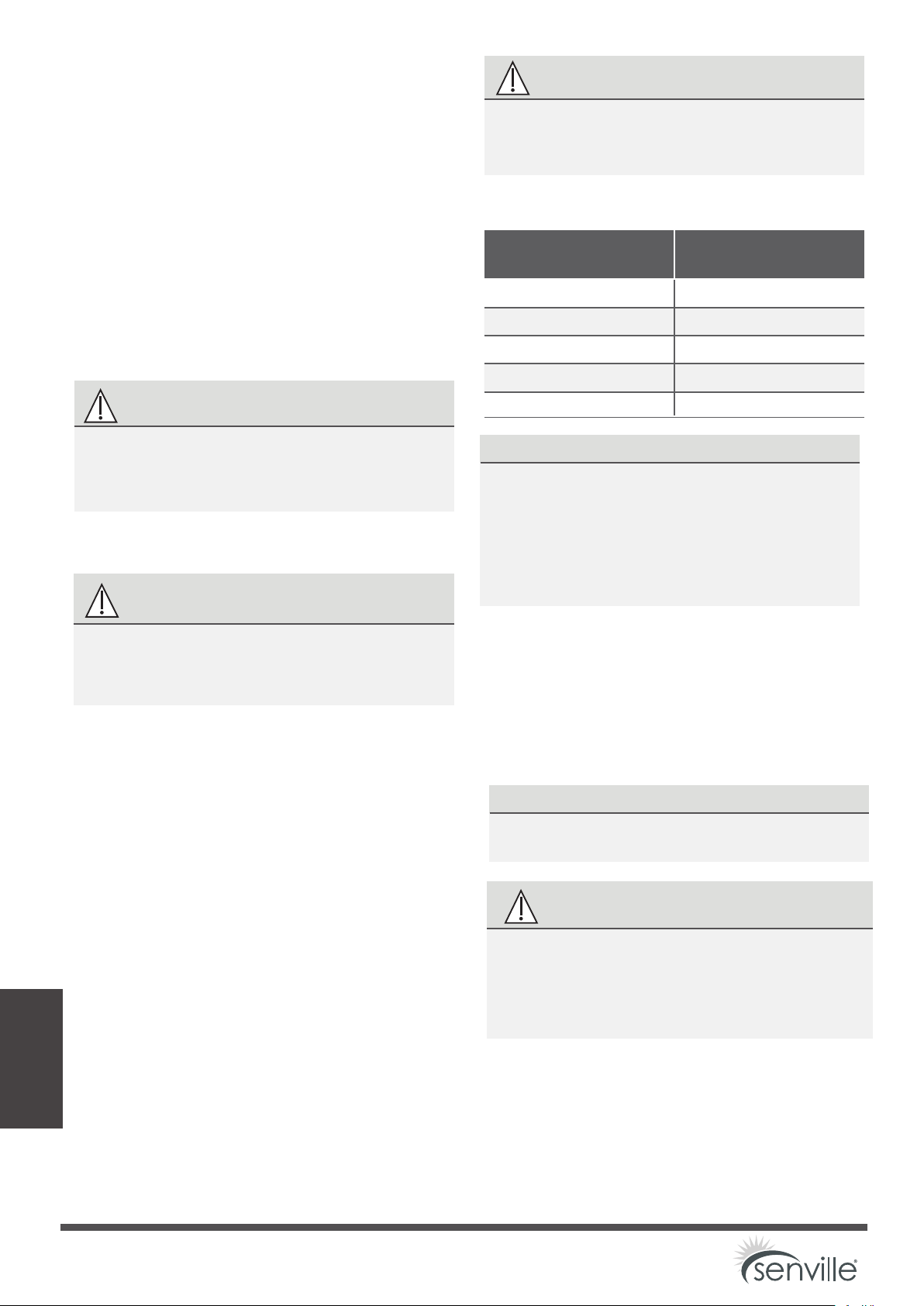
Appliance Amps (A)
AWG
15 14
20
12
30 10
40 8
55 6
1. Prepare the cable for connection:
a. Using wire strippers, strip the rubber
jacket from both ends of cable to reveal
about 40mm (1.57in) of the wires inside.
b. Strip the insulation from the ends of the
wires.
c. Using a wire crimper, crimp u-lugs on the
ends of the wires.
PAY ATTENTION TO LIVE WIRE
While crimping wires, make sure you clearly
distinguish the Live (“L”) Wire from other wires.
WARNING
ALL WIRING WORK MUST BE PERFORMED
STRICTLY IN ACCORDANCE WITH THE
WIRING DIAGRAM LOCATED INSIDE OF
WIRE COVER OF THE OUTDOOR UNIT .
CHOOSE THE RIGHT CABLE SIZE
The size of the power supply cable, signal cable,
fuse, and switch needed is determined by the
maximum current of the unit. The maximum
current is indicated on the nameplate located on
the side panel of the unit. Refer to this nameplate
to choose the right cable, fuse, or switch.
Page 30
Loading ...
Loading ...
Loading ...