Loading ...
Loading ...
Loading ...
Indoor Unit
Installation
SENA/18HF/IQ
SENA/24HF/IQ
SENA/09HF/IQ
SENA/12HF/IQ
Indoor unit outline
Unit: mm(inch)
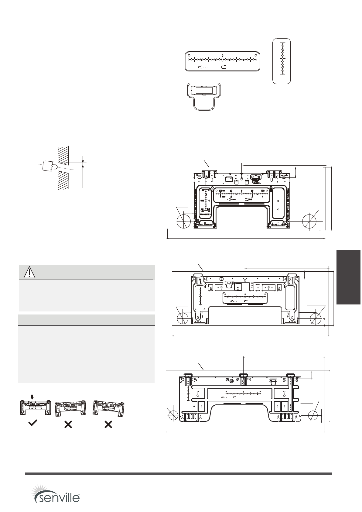
Step 3: Drill wall hole for connective piping
1. Determine the location of the wall hole based
CAUTION: The Bubble level on the mounting
plate can’t be removed. If it is broken, make
sure to clean up the leaking liquid.
Vertical
direction ruler
Horizontal direction ruler
on the position of the mounting plate. Refer
to Mounting Plate Dimensions.
Wall
IndoorOutdoor
mm7-5
(0.2-0.275in)
Fig.3.2
MOUNTING PLATE DIMENSIONS
Different models have different mounting plates.
For the convenience of installation, there are
bubble level, carved dimensions on the
mounting plate. Please install the plate and drill
wall hole according to the information of the
mounting plate. See the figures below.
Correct orientation of Mounting Plate
2. Using a 65mm (2.5in) or 90mm(3.54in)
(depending on models )core drill, drill a
hole in the wall. Make sure that the hole
is drilled at
a slight downward angle, so
that the outdoor end of the hole is lower
than the indoor end by about 5mm to
7mm (0.2-0.275in). This will ensure proper
water drainage.
3. Place the protective wall cuff in the hole.
This protects the edges of the hole and
will help seal it when you finish the
installation process.
CAUTION
When drilling the wall hole, make sure
to
avoid wires, plumbing, and other
sensitive components.
Φ
Φ
NOTE: When the gas side connective pipe is
16mm(5/8in) or more, the wall hole should
be 90mm(3.54in).
FROM EDGE TO HOLE CENTER:50mm
FROM EDGE TO HOLE CENTER:50mm
FROM EDGE TO HOLE CENTER:95mm
FROM EDGE TO HOLE CENTER:70mm
150
100
100
965(38)
795(31)
50(1.9)
95(3.7)
120(4.7)
570.7(22.5)
70(2.8)
1140(44.8)
50(1.9)
pipe hole
65(2.5)
Φ
pipe hole
65(2.5)
Φ
pipe hole
65(2.5)
Φ
pipe hole
65(2.5)
Φ
pipe hole
65(2.5)
50(1.9)
Φ
pipe hole
65(2.5)
490(19.3)
425(16.7)
322(12.7)
295(11.6)
370(14.6)
50(1.9)
40(1.6)
40(1.5)
60(2.4)
51(2.0)
100
50
50
50
2
2
2
4
4
4
6
RECOMMAND
LIQUID
GAS
BUBBLE
LEVEL
BUBBLE
LEVEL
mm
inch
150
100
50
2
4
6
RECOMMAND
mm
inch
mm
inch
100
100
50
50
2
2
4
4
LIQUID
GAS
mm
inch
FROM EDGE TO HOLE CENTER:50mm
FROM EDGE TO HOLE CENTER:100mm
150
100
100
100
50
50
50
2
2
2
4
4
4
6
RECOMMAND
LIQUID
GAS
BUBBLE
LEVEL
mm
inch
mm
inch
FROM EDGE TO HOLE CENTER:50mm
FROM EDGE TO HOLE CENTER:100mm
150
100
100
100
50
50
50
2
2
2
4
4
4
6
RECOMMAND
LIQUID
GAS
BUBBLE
LEVEL
mm
inch
mm
inch
FROM EDGE TO HOLE CENTER:50mm
FROM EDGE TO HOLE CENTER:100mm
150
100
100
100
50
50
50
2
2
2
4
4
4
6
RECOMMAND
LIQUID
GAS
BUBBLE
LEVEL
mm
inch
mm
inch
BUBBLE
LEVEL
150
100
50
2
4
6
RECOMMAND
mm
inch
100
100
50
50
2
2
4
4
LIQUID
GAS
mm
inch
40(1.6)
Indoor unit outline
Indoor unit outline
Page 21
Loading ...
Loading ...
Loading ...