Loading ...
Loading ...
Loading ...
Indoor Unit
Installation
Installation Instructions – Indoor unit
PRIOR TO INSTALLATION
Before installing the indoor unit, refer to the
label on the product box to make sure that the
model number of the indoor unit matches the
model number of the outdoor unit.
Step 1: Select installation location
Before installing the indoor unit, you must
choose an appropriate location. The following
are standards that will help you choose an
appropriate location for the unit.
Proper installation locations meet the
following standards:
Good air circulation
If the back holder is not needed to prop
up the unit:
Finishing the pipe and cable connections
before mount the indoor unit on the wall.
If the installation height is limited, 5cm from
the ceiling is allowable, but this can lower
product performance. To ensure enough
space to install and remove the top air filter,
keep at least 10cm or more from the ceiling.
The back holder is needed to prop up the
unit: If connecting pipe and cable with front
panel open, the minimum distance from
ceiling is 22cm or more, if connecting pipe
and cable without front panel(remove it) , the
minimum distance from ceiling is 11cm or
more.
Convenient drainage
Noise from the unit will not disturb other
people
Firm and solid—the location will not vibrate
Strong enough to support the weight of the
unit
A location at least one meter from all other
electrical devices (e.g., TV, radio, computer)
DO NOT
install unit in the following
locations:
Near any source of heat, steam, or
combustible gas
Near flammable items such as curtains or
clothing
Near any obstacle that might block air
circulation
Near the doorway
In a location subject to direct sunlight
NOTE ABOUT WALL HOLE:
If there is no fixed refrigerant piping:
While choosing a location, be aware that you
should leave ample room for a wall hole (see
Drill wall hole for connective piping step)
for the signal cable and refrigerant piping
that connect the indoor and outdoor units.
The default position for all piping is the right
side of the indoor unit (while facing the unit).
However, the unit can accommodate piping to
both the left and right.
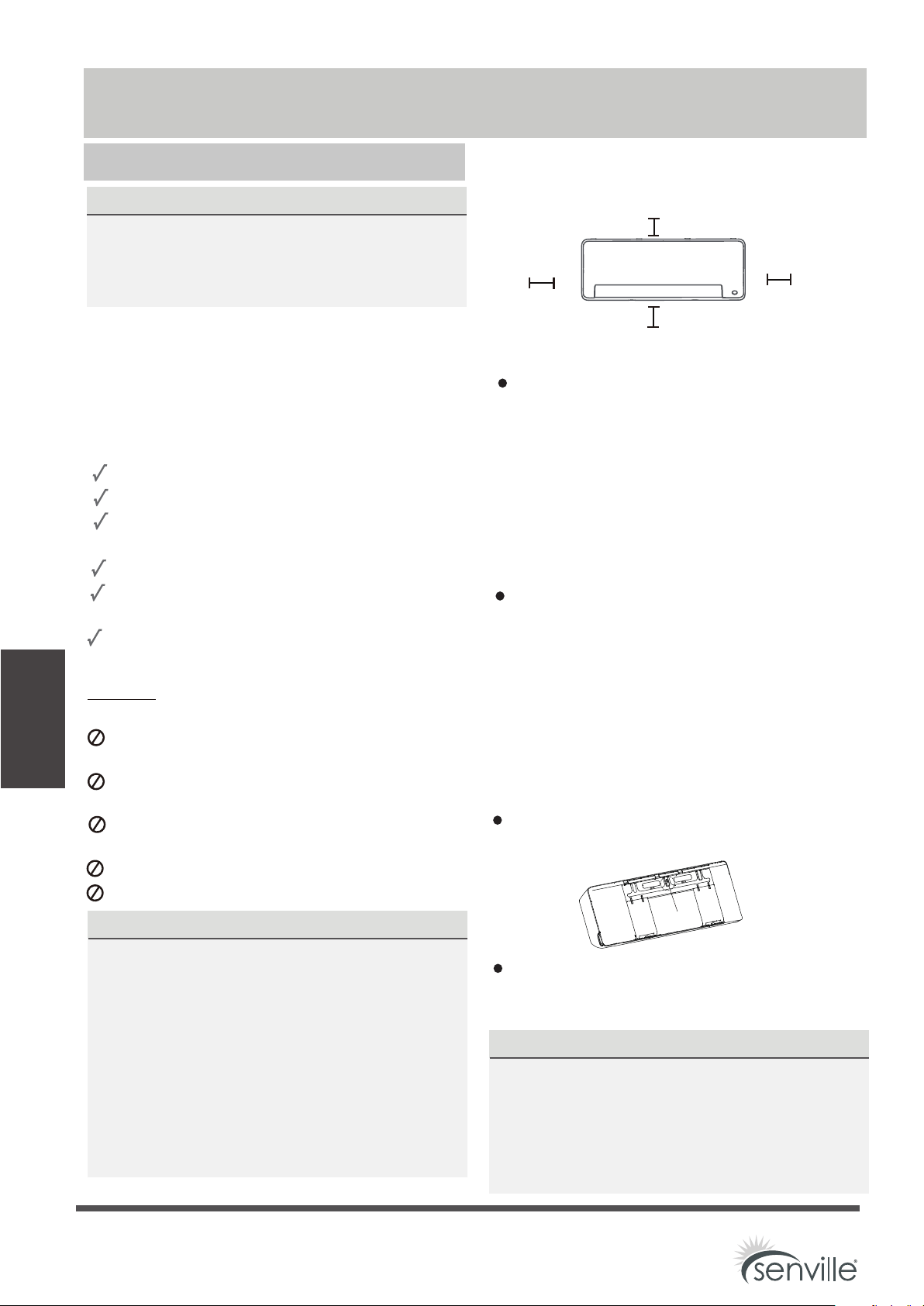
Refer to the following diagram to ensure
proper distance from walls and ceiling:
NOTE:
Step 2: Attach mounting plate to wall
The mounting plate is the device on which you
will mount the indoor unit.
Remove the screw that attaches the mounting
plate to the back of the indoor unit.
Secure the mounting plate to the wall with
screws. Make sure that mounting plate is flat
against the wall.
12cm (4.72in)
or more
2.3m (90.55in) or more
12cm (4.72in)
or more
Distance from ceiling is determinded
by the installation method.
NOTE FOR CONCRETE OR BRICK WALLS:
If the wall is made of brick, concrete, or similar
material, drill 5mm-diameter (0.2in-diameter)
holes in the wall and insert the sleeve anchors
provided. Then secure the mounting plate to
the wall by tightening the screws directly into
the clip anchors.
Screw
Indoor Unit Installation
Page 20
Loading ...
Loading ...
Loading ...