Loading ...
Loading ...
Loading ...
Step-by-stepinstallation instructions.
• Turn off the gas or elecuic supply to tile water heater, in tile possibiliff that the
water heater may be chained while &aining pipes.
• Turn off the w;iter supply to pipes to be cut and chain the h_)use water pipes.
• Open both hot and coM fimcets.
1. INSTALL BYPASS VALVE
• Rem()ve plastic shipping plug and wire flom valve outlet.
NOTE: Be sure the turbine
and support me firmly in
place in the xvtlve outlet.
Blow into the xvdve port
and observe the turbine
tot fiee rotation.
Turbine
e outlet
Turbine sMft
and suppo_
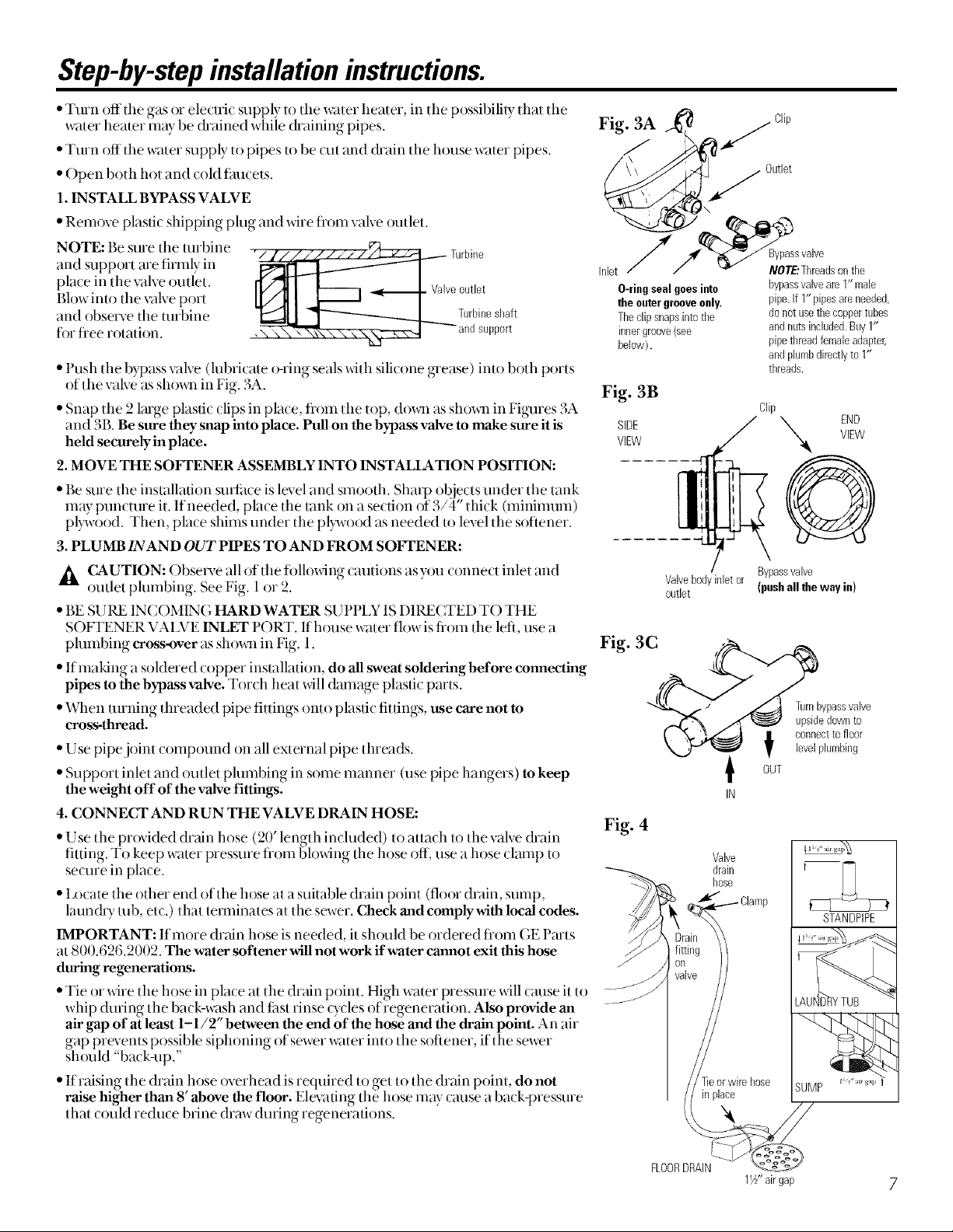
Fig. 3A
Met
O-ringseal goesinto
the outergrooveonly.
Theclip snapsinto the
innergroove(see
below).
• Push the bypass xvdve (lubricate o-ring seals with silicone grease) into both ports
of the valve as shm_ql in Fig. 3A. Fig. 3B
° Snap the 2 large plastic clips in place, flom the top, dox_11 as shox_i_ in Figures 3A
and 3B. Be sure they snap into place. Pull on the bypass valve to make sure it is SIDE
held securely in place. VIEW
2. MOVE THE SOFTENER ASSEMBLY INTO INSTALLATION POSITION:
• Be sure the installation suriime is level and smooth. Sharp objects under tile tank
mW puncune it. If needed, place the lank on a section of 3/4" thick (minimum)
pl)wood. Then, place shims under the pl)wood as needed to level the softener.
3, PLUMB INAND OUT PIPES TO AND FROM SOFTENER:
CAUTION: Obsecve all of tile tbllowing cautions as you connect inlet and
outlet plumbing. See Fig. 1 or 2.
• BE SURE IN( OMING HARD WATER SUPPI N IS DIRECTED TO THE
SOFTENER VA137E INLET PORT. If house w;tter flow isfioln the left, use a
plumbing cross-over as shox_l_in Fig. 1.
• If making a soMered copper installation, do all sweat soldering before connecting
pipes to the bypass,calve. Torch heat will damage plastic pmls.
• When turning threaded pipe fittings onto plastic fittings, use care not to
cross-thread.
° Use pipe joint compound on all external pipe flneads.
• )"
Support inlet and outer phnnbing in some manner (use pipe hangers) to keep
the weight off of the valve fittings.
4. CONNECt AND RUN THE VALVE DRAIN HOSE:
Clip
J
Outlet
° Use tile provided dr?fin hose (20' length included) to attach to tile valve &ain
fitting. To keep water pressure tiom bh)wing tile hose off, use a hose clamp tO
seone in place.
• I_ocate the other end of the hose at a suitable drain point (floor drain, sump,
laund U rob, et_.) that temfinates at the sewer. Check and comply with local codes.
IMPORTANT: If more drain hose is needed, it sh{)uM be ordered flom GE Pmts
at 800.626.2002. The water softener will not work if water cannot exit this hose
during regenerations.
• Tie or wire the hose in place at the drain point. High water pressure will cruise it to
whip during the back-w:tsh and tast rinse tycles of regeneration. Also provide an
ak gap of at least 1-1/2" between the end of the hose and the drain point. An air
gap prevents possible siphoning of sewer water into the softener, if the sewer
sh_)uld "back-up."
° If raising tlle drain hose overhead is required to get to file drain point, do not
raise higher than 8' above the floor. Elevating the hose may _ause a ba_ k-pressme
that could reduce brine draw during regenerations.
Valvebodyinletor
outlet
Bypassvalve
NOT£'Thmadsonthe
bypassvalveam 1" male
pipe.if 1" pipesare needed,
do not usethecoppertubes
and nutsincluded.Buy 1"
pipethreadfemaleadapter,
and plumbdirectlyto I"
threads.
Clip
X END
VIEW
Q
Bypassvalve
(pushall the way in)
Fig. 3C
Fig. 4
Valye
drain
hose
Turnbypassvalve
upsidedownto
connectto floor
levelplumbing
STANDPIPE
ur gap
FLOORDRAIN
1½"airgap 7
Loading ...
Loading ...
Loading ...