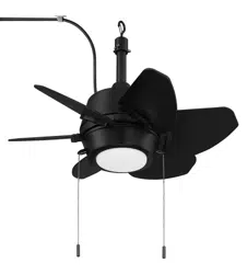
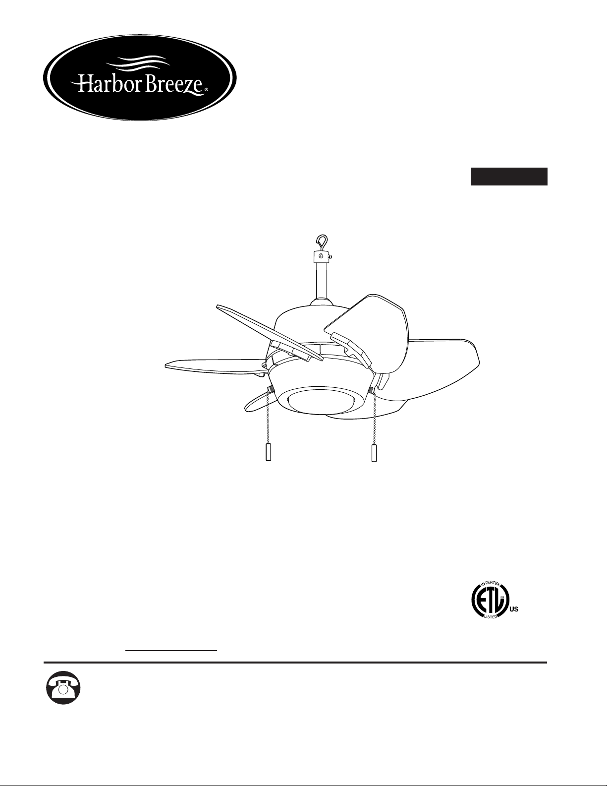
GASKIN CEILING FAN
ITEM #2889555
MODEL #GAT24MBK6LOD
Questions, problems, missing parts? Before returning to your retailer, call our customer
service department at 1-888-251-1003, 8 a.m. - 8 p.m., EST, Monday - Sunday. You could
also contact us at [email protected] or visit www.lowespartsplus.com
Purchase Date
1
Español p. 16
ATTACH YOUR RECEIPT HERE
ADJUNTE SU RECIBO AQUÍ
Harbor Breeze® and logo design are
trademarks or registered trademarks
of LF, LLC. All Rights Reserved.
JS20025
4007498
APPROVED FOR USE IN
WET LOCATIONS
TABLE OF CONTENTS
2
Modifications not approved by the party responsible for compliance could void the user's authority to
operate the equipment.
*NOTE: This equipment has been tested and found to comply with the limits for a Class B digital
device, pursuant to Part 15 of the FCC Rules. These limits are designed to provide reasonable
protection against harmful interference in a residential installation. This equipment generates,
uses and can radiate radio frequency energy and, if not installed and used in accordance with the
instructions, may cause harmful interference to radio communications. However, there is no
guarantee that interference will not occur in a particular installation. If this equipment does cause
harmful interference to radio or television reception, which can be determined by turning the
equipment off and on, the user is encouraged to try to correct the interference by one or more of
the following measures:
* Reorient or relocate the receiving antenna.
* Increase the separation between the equipment and receiver.
* Connect the equipment into an outlet on a circuit different from that to which the receiver is
connected.
Consult the dealer or an experienced radio/TV technician for help.
Distributed by: Litex Industries Inc., P.O. Box 535639, Grand Prairie, TX, 75053
The device complies with Part 15 of the FCC Rules. Operation is subject to the following two
conditions: (1) this device may not cause harmful interference, (2) this device must accept any
interference received, including interference that may cause undesired operation.
SAFETY INFORMATION
Safety Information ........................................................................................................................ 2
Package Contents ........................................................................................................................ 5
Hardware Contents ...................................................................................................................... 6
Preparation .................................................................................................................................
..
6
Initial Installation ........................................................................................................................... 7
Final Installation ............................................................................................................................ 9
Operating Instructions .............................................................................................................. 12
Troubleshooting.........................................................................................................................
..
14
Care and Maintenance ............................................................................................................... 15
Limited Lifetime Warranty ..........................................................................................................
.
15
Replacement Parts List .............................................................................................................. 15
READ AND SAVE THESE INSTRUCTIONS
• Do not discard fan carton or foam inserts. Should this fan need to be returned to the factory for
repairs, it must be shipped in its original packaging to ensure proper protection against damage that
might exceed the initial cause for return.
• Make sure all electrical connections comply with local codes, ordinances, the National Electrical
Code and ANSI/NFPA 70-1999. Hire a qualified electrician or consult a do-it-yourself wiring
handbook if you are unfamiliar with installing electrical wiring.
• Make sure the installation site you choose allows a minimum clearance of 7 ft. from the blades to
the floor and at least 30 in. from the end of the blades to any obstruction.
• After you install the fan, make sure all connections are secure to prevent the fan from falling.
• The net weight of this fan including the light kit is: 13 lbs.
SAFETY INFORMATION
3
DO NOT suspend any fixture by the house wires. Fan must always be mounted
directly to an eye bolt which is first attached to the building structure. The power cord
alone will not support the weight of the fan. Suspending a fan by the plug will result in
the fan falling, with the possibility of personal injury and the danger of electrical shock or fire.
Secure the eye bolt directly to the building structure. The eye bolt and its support must be able to
support the moving weight of the fan (at least 35 lbs.).
To avoid personal injury, the use of gloves may be necessary while handling fan parts with sharp
edges.
To reduce the risk of fire or electrical shock, do not use the fan with any solid-state speed control
device or control fan speed with a full range dimmer switch.
To reduce the risk of fire, electrical shock or personal injury, do not bend the blades when
installing or balancing them or cleaning the fan. Do not insert objects between the rotating fan
blades.
WARNING
DANGER
When using an eye bolt, make sure the eye bolt is securely attached to the building structure
and can support the full weight of the fan. Failure to do this can result in serious injury or death.
The stability of the eye bolt is essential in minimizing wobble and noise in the fan after installation
is complete.
To reduce the risk of serious bodily injury, DO NOT use power tools to assemble any part of the
fan, including the blades.
If using this fan in a WET location, connect this product to a Ground Fault Circuit Interrupting
(GFCI) outlet to reduce the risk of personal injury, electrical shock or death. If one is not provided,
contact a qualified electrician for proper installation.
4
SAFETY INFORMATION
CAUTION
Read all instructions and safety information before installing your new fan. Review the
accompanying assembly diagrams.
Once installation is complete, carefully check all screws, bolts and nuts on fan motor assembly to
ensure that they are secured.
Do NOT tamper with or attempt to repair LED component. The light source is designed for this
specific application and should not be serviced by untrained personnel. If any servicing is
required, call our customer service department.
This portable fan has a polarized plug (one blade is wider than the other) as a safety feature to
reduce the risk of electric shock. This plug will fit in a polarized outlet only one way. If it does not fit
fully in the outlet, reverse the plug. If it still does not fit, contact a qualified electrician. NEVER use
with an extension cord unless the plug can be fully inserted. DO NOT alter the plug.
To reduce the risk of personal injury, use only parts provided with this fan. The use of parts
OTHER than those provided with this fan will void the warranty.
To reduce the risk of electric shock, DO NOT use the product if power cord is frayed or broken.
To reduce the risk of burns, fire, electric shock or injury to persons, unplug from outlet before
putting on or taking off parts.
As a safety precaution, unplug power supply cord when not in use.
DO NOT use staples or nails to secure wiring/power supply cord from light fixture.
DO NOT place wiring/power supply cord on sharp hooks or nails.
DO NOT hang ornaments or other objects from power supply cord, wire or lights.
DO NOT close doors and/or windows on the light fixture power supply cord as doing so may
damage the insulation wire(s).
WARNING
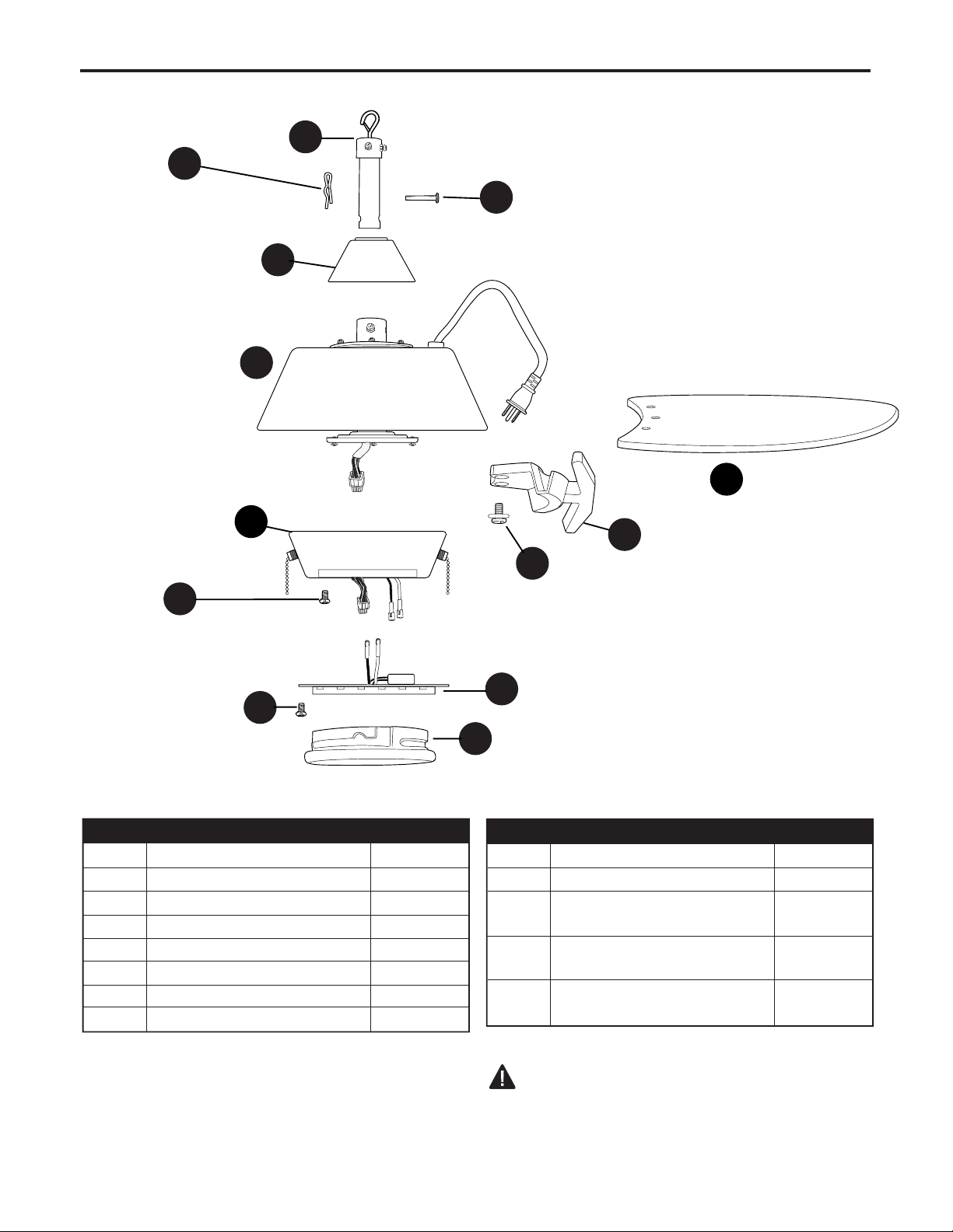
A
B
D
I
H
G
IMPORTANT REMINDER: You must use the
parts provided with this fan for proper installation
and safety.
A Downrod 1
B Motor Housing 1
C Yoke Cover 1
D LED Light Kit 1
E Blade 6
F Switch Housing 1
G Shade 1
H Pin (preassembled) 1
DESCRIPTIONPART
QUANTITY
PACKAGE CONTENTS
5
C
K
DESCRIPTIONPART
QUANTITY
I Clip (preassembled) 1
J Blade Arm 6
K Switch Housing Screw 3
(preassembled)
L Motor Plate Screw 3
(preassembled)
M Motor Screw/Lock Washer 12
(preassembled) + 1 extra
F
E
J
M
L
6
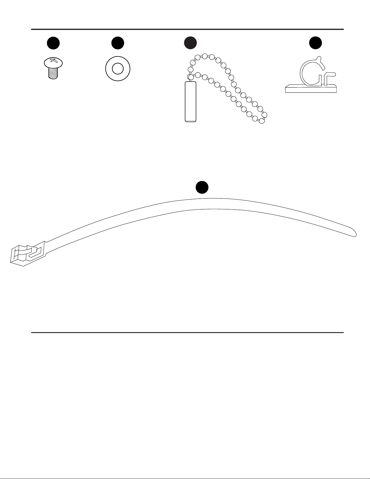
PREPARATION
HARDWARE CONTENTS (shown actual size)
Before beginning assembly of product, make sure all parts are present. Place motor on carpet or on
foam to avoid damage to finish. Compare parts with package contents list and hardware contents list. If
any part is missing or damaged, do not attempt to install, operate or assemble the product.
Estimated Assembly Time: 60 minutes.
Tools Required for Assembly (not included): Phillips Screwdriver, Pliers, Safety Glasses, Stepladder.
Helpful Tools (not included): AC Tester Light, Tape Measure.
AA
BB
Blade
Screw
Qty. 18
+ 1 extra
CC
Rubber
Blade
Washer
Qty. 18
+ 1 extra
Zip Tie
Qty. 1
Clamp
Qty. 6
Pull Chain
Extension
Qty. 2
EE
DD
7
INITIAL INSTALLATION
1.
Remove preassembled motor screws/lock washers
(M) from underside of motor housing (B). If there
are plastic motor blocks installed with the motor
screws/lock washers (M), discard the plastic motor
blocks.
Note: Make sure to keep loose hardware separate
to avoid confusion during installation.
1
M
B
Plastic
Motor
Block
Remove pin (H) and clip (I) from downrod (A).
Partially loosen preassembled set screws and nut
in motor housing yoke at top of motor housing (B).
2a.
2a
H
I
2b
A
Set Screw
Sideview
B
Yoke
2b.
3.
Insert downrod (A) through yoke cover (C). Slip
downrod (A) into motor housing yoke, align holes
and re-install pin (H) and clip (I). Tighten set
screws in motor housing yoke and then tighten
preassembled nut on one of the set screws. Then,
slide yoke cover (C) down until it rests on top of
motor housing (B).
3
B
C
I
H
Yoke
H
I
Set Screw
and Nut
Sideview
A
8
INITIAL INSTALLATION
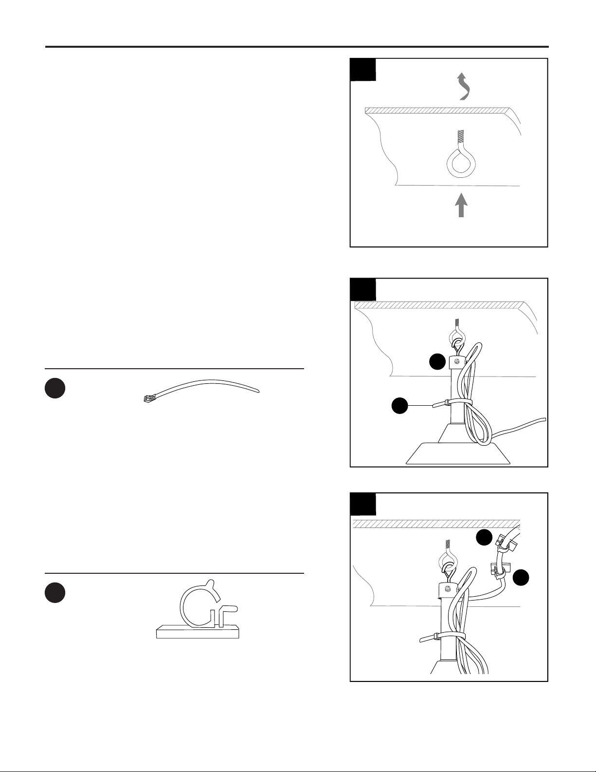
6.
Remove liner from back of clamp (DD). Place
clamps (DD) alongside the path of the power cord
and insert power cord into clamps (DD), making
sure the cord does not hang in the way of the fan.
6
Hardware Used
Clamp
x 6
DD
5.
Clip downrod (A) to secured eye bolt. Check the
length of the power cord from the outlet to the fan
(do NOT plug in the fan). Using the zip tie (EE)
secure power cord slack to the side of the
downrod.
5
Hardware Used
Zip Tie
x 1
EE
EE
4.
4
Secure an eye bolt (not included) to ceiling of
building structure.
*NOTE: It is very important you use the proper
hardware when installing the eye bolt as this will
support the fan.
DD
DD
A
9
FINAL INSTALLATION
DANGER: To reduce the risk of serious bodily
injury, DO NOT use power tools to assemble the
blades (E). If screws are overtightened, blades (E)
may crack and break.
Partially insert three blade screws (AA) along with
three rubber blade washers (BB) into holes in blade
(E) (labeled THIS SIDE UP) to attach blade arm (J) to
blade (E). Then, tighten each blade screw (AA)
starting with the one in the middle.
Repeat Step 2 for remaining blades (E) and blade
arms (J).
1.
Rubber Blade Washer x 18
BB
Hardware Used
1
BB
AA
E
J
AA
Blade Screw x 18
B
2
E
J
Attach blade arms (J) to the bottom of motor housing
(B) with motor screws/lock washers (M) previously
removed (Step 1, page 6). Tighten motor screws/lock
washers (M) securely.
NOTE: Make sure to completely secure each blade
arm (J) before proceeding to the next.
2.
M
3.
Remove one motor plate screw (L) from motor
plate preassembled on the underside of the motor
housing (B) and partially loosen the other two
motor plate screws (L). Align slotted holes in
switch housing (F) with loosened motor plate
screws (L), allowing molex connections from
motor housing (B) to come through hole in switch
housing (F). Twist switch housing (F) to lock.
Re-insert the motor plate screw (L) that was
removed and securely tighten all three motor plate
screws (L).
3
I
L
I
L
I
L
F
B
Motor
Plate
10
FINAL INSTALLATION
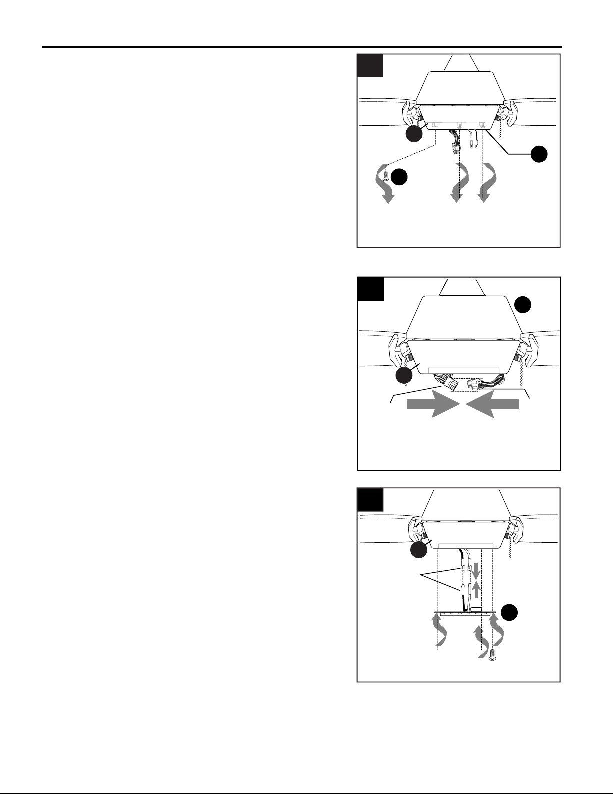
4.
Remove two switch housing screws (K) from
underside of switch housing (F) and partially
loosen the other switch housing screw (K).
3
4
K
K
F
D
molex
connections
6
Connect WHITE molex wire from LED light kit (D)
to WHITE molex wire from switch housing (F).
Connect BLUE molex wire from LED light kit (D) to
BLACK (or BLUE) molex wire from switch housing
(F). Make sure molex wire connections snap
together securely.
6.
F
5.
Connect male plug from motor housing (B) to female
plug from switch housing (F), matching up the colors
on the male plug with the colors on the female plug
for correct fit. Make sure plugs are connected
completely.
5
B
Male
Plug
Female
Plug
F
11
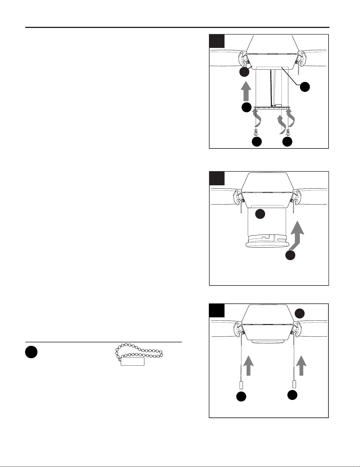
FINAL INSTALLATION
D
F
Carefully arrange wires inside switch housing (F).
Align hole in edge of LED light kit (D) with loosened
switch housing screw (K) in switch housing (F).
Re-insert the other two switch housing screws (K)
previously removed. Tighten all three switch
housing screws (K) securely.
7.
3
7
K
Align slots on shade (G) with protrusions on the
inside of the switch housing (F). Turn shade (G) to
the right (clockwise) until it no longer turns.
NOTE: Pull down gently on the shade (G) to make
sure that it is secured completely.
8.
3
8
G
KK
B
Attach pull chain extensions (CC) or custom pull
chain extensions (not included) to fan and light pull
chains.
9.
9
CC
CC
Pull Chain Extension x 2
Hardware Used
CC
F
12
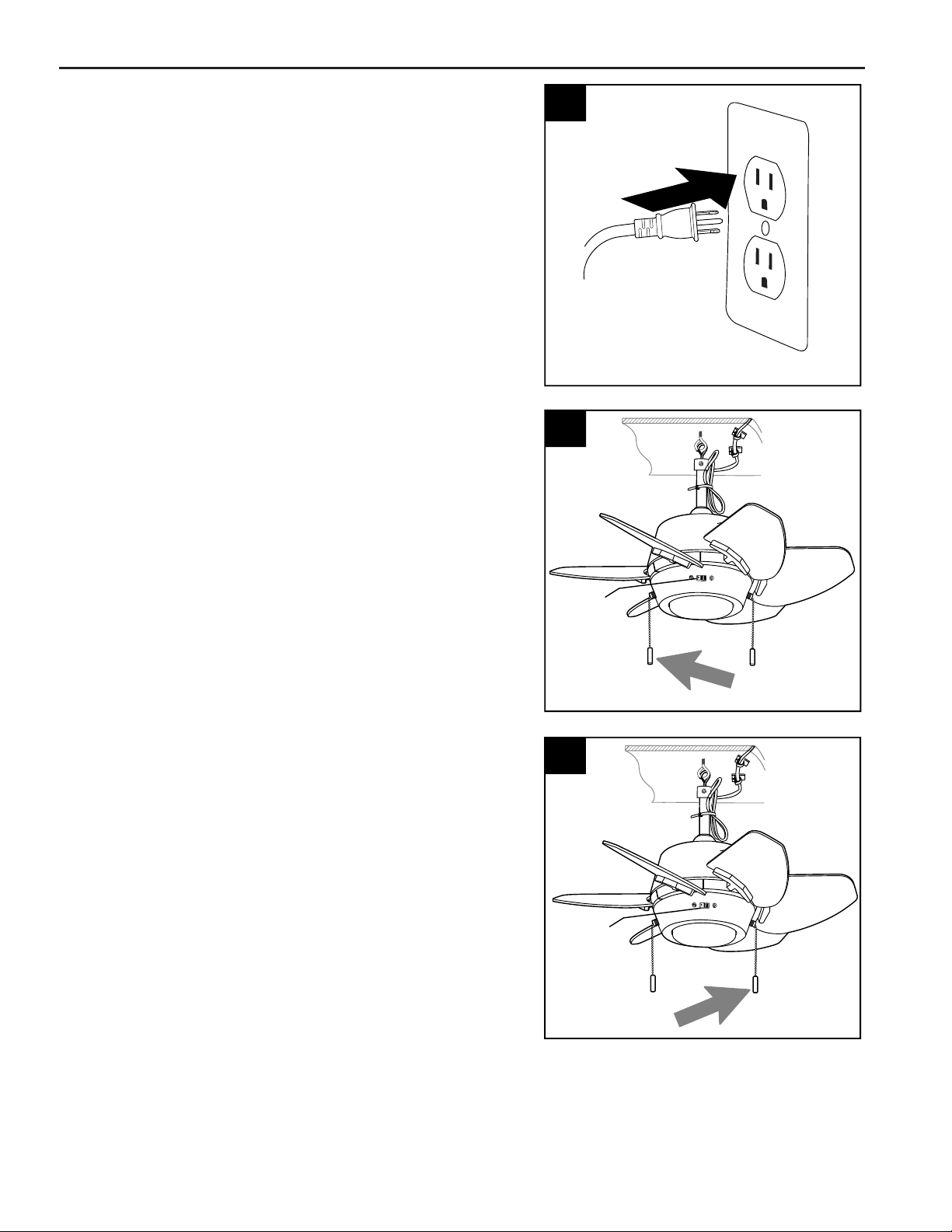
The light pull chain, located to the right of the reverse
switch, is used to turn the light ON or OFF.
OPERATING INSTRUCTIONS
The fan pull chain, located to the left of the
reverse switch, has four positions to control fan
speed. One pull is HIGH, two is MEDIUM, three
is LOW and four turns the fan OFF.
2.
2
Reverse
Switch
Plug power cord into outlet.
DANGER: If using this fan in a WET or DAMP
location, connect this product to a Ground Fault
Circuit Interrupting (GFCI) outlet to reduce the
risk of personal injury, electrical shock or death.
If one is not provided, contact a qualified
electrician for proper installation.
1.
3.
3
1
Reverse
Switch
13
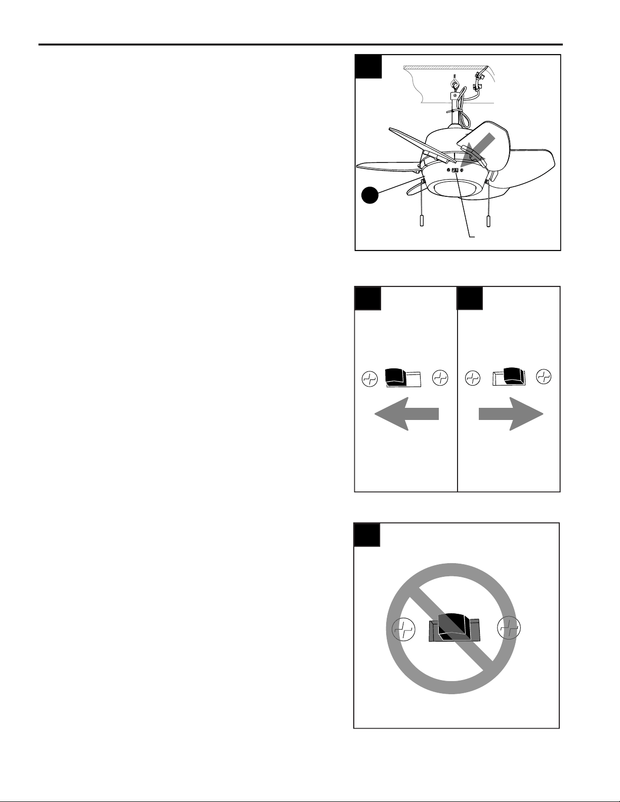
OPERATING INSTRUCTIONS
Use the fan reverse switch on the switch housing
(F) to optimize your fan for seasonal performance.
A ceiling fan will allow you to raise your thermostat
setting in summer and lower your thermostat
setting in winter without feeling a difference in your
comfort.
NOTE: Wait for fan to stop before moving the
reverse switch.
4.
Reverse Switch
F
4
4a
4b
4a. In warmer weather, setting the reverse switch
in the LEFT position will result in downward airflow
creating a wind chill effect.
4b. In cooler weather, setting the reverse switch
in the RIGHT position will result in upward airflow
that can help move stagnant, hot air off the ceiling
area.
4c
4c. IMPORTANT: Reverse switch must be set
either completely LEFT or completely RIGHT for
fan to function. If the reverse switch is set in the
middle position, fan will not operate.

14
WARNING: Before beginning work, unplug fan to avoid electrical shock.
TROUBLESHOOTING
PROBLEM POSSIBLE CAUSE CORRECTIVE ACTION
Fan does not move. 1. Reverse switch not engaged.
2. Power is off or fuse is blown.
3. Plugs in switch housing not connected
properly.
1. Push switch firmly either left or
right.
2. Turn power on or check fuse.
Make sure fan is plugged in
correctly.
3. Check that male and female plugs
in switch housing are connected
properly according to instructions
on page 10.
Noisy operation. 1. Blades are loose.
2. Cracked blade.
3. Fan is new.
1. Tighten all blade screws.
2. Replace blade.
3. Allow fan a “break in” period of
a few days, especially when
running the fan at Medium and
High speeds.
Excessive wobbling.
1. Blades are loose.
2. Blade arms incorrectly attached.
3. Unbalanced blades.
4. Fan not securely mounted.
5. Fan too close to vaulted ceiling.
6. Set screw(s) on motor housing yoke is
(are) not tightened properly.
1. Tighten all blade screws.
2. Re-install blade arms.
3. Switch one blade with a blade
from the opposite side.
4. Turn power off. Make sure eye
bolt is secured to structure.
5. Use a longer downrod or move
fan to another location.
6. Tighten yoke set screw(s)
securely.
Fan operates but
light fails.
1. Wall switch to fan is off.
2. Wires in LED light kit not wired
correctly.
1. Make sure that wall switch to fan
is on.
2. Check that molex connections in
LED light kit are connected
properly according to instructions
on page 10.
NOTE: A small amount of "wobble" is normal and should not be considered a defect.
15
E
PART DESCRIPTION
2889555-A
2889555-E
2889555-J
PART #
A
A Downrod
E Blade
J Blade Arm
J
Printed in China
REPLACEMENT PARTS LIST
LIMITED LIFETIME WARRANTY
The distributor warrants this fan to be free from defects in workmanship and materials present at time of
shipment from the factory for Lifetime limited from the date of purchase. This warranty applies only to the
original purchaser. The distributor agrees to correct any defect at no charge or, at our option, replace the
ceiling fan with a comparable or superior model.
To obtain warranty service, present a copy of your sales receipt as proof of purchase. All cost of removal
and reinstallation are the express responsibility of the purchaser. Any damage to the ceiling fan by
accident, misuse or improper installation, or by using parts not produced by the manufacturer of this fan or
affixing accessories not produced by the manufacturer of this fan, are the purchaser's own responsibility.
The distributor assumes no responsibility whatsoever for fan installation during the limited lifetime warranty.
Any service performed by an unauthorized person will render the warranty invalid.
Due to varying climatic conditions, this warranty does not cover changes in brass finish, rusting, pitting,
tarnishing, corroding or peeling. Brass finish fans maintain their beauty when protected from varying
weather conditions. Any glass provided with this fan is not covered by the warranty.
Any replacement of defective parts for the ceiling fan must be reported within the first year from the date of
purchase. For the balance of the warranty, call our customer service department (at 1-888-251-1003) for
return authorization and shipping instructions so that we may repair or replace the ceiling fan. Any fan or
parts returned improperly packaged is/are the sole responsibility of the purchaser. There is no further
express warranty. The distributor disclaims any and all implied warranties. The duration of any implied
warranty which cannot be disclaimed is limited to the limited lifetime period as specified in our warranty.
The distributor shall not be liable for incidental, consequential or special damages arising at or in
connection with product use or performance except as may otherwise be accorded by law. This warranty
gives you specific legal rights and you may also have other rights which vary from state to state. This
warranty supersedes all prior warranties.
GGLI2012
For replacement parts, call our customer service department at 1-888-251-1003, 8 a.m. - 8 p.m., EST,
Monday - Sunday. You could also contact us at [email protected] or visit www.lowespartsplus.com
CARE AND MAINTENANCE
At least twice each year, tighten the eye bolt holding the downrod (A), and then tighten all screws on
fan. Clean motor housing (B) with only a soft brush or lint-free cloth to avoid scratching the finish.
Clean blades (E) with a lint-free cloth. You may occasionally apply a light coat of furniture polish to
wood blades for added protection.
IMPORTANT: Unplug fan before beginning any maintenance. Do not use water or a damp cloth to
clean the ceiling fan.
Total wattage for this fan is 12 watts; do not attempt to replace the LEDs.
