Loading ...
Loading ...
Loading ...
39
Location
U.S. Installation Requirements
1
Canadian Installation Requirements
2
A = Clearance above grade, veranda, porch, deck, or
balcony�
12 in� (30 cm) 12 in� (30 cm)
B = Clearance to window or door that may be opened�
• 6 in� (15 cm) for water heaters less than or
equal to 10,000 Btuh (3 kW)�
• 9 in� (23 cm) for water heaters greater than
10,000 Btuh (3 kW) and less than or equal
to 50,000 Btuh (15 kW)�
• 12 in� (30 cm) for water heaters greater
than 50,000 Btuh (15 kW)
3
�
• 6 in� (15 cm) for water heaters less than
or equal to 10,000 Btuh (3 kW)�
• 12 in� (30 cm) for water heaters greater
than 10,000 Btuh (3 kW) and less than or
equal to 100,000 Btuh (30 kW)�
• 36 in� (91 cm) for water heaters greater
than 100,000 Btuh (30 kW)�
C = Clearance to permanently closed window�
D = Vertical clearance to ventilated soffit located
above the terminal within a horizontal
distance of 2 ft� (61 cm) from the centerline of the
terminal�
36 in (91 cm) recommended
4
36 in (91 cm) recommended
4
E = Clearance to unventilated soffit�
36 in (91 cm) recommended
4
36 in (91 cm) recommended
4
F = Clearance to outside corner�
G = Clearance to inside corner�
18 in (46 cm) recommended
4
18 in (46 cm) recommended
4
H = Clearance to each side of centerline
extended above meter/regulator assembly�
3 ft� (91 cm) within a height of 15 ft� (4�57
m) above the meter/regulator assembly�
I = Clearance to service regulator vent outlet�
3 ft� (91 cm)
J = Clearance to nonmechanical air supply inlet to
the combustion air inlet to any building or other
appliance�
• 6 in� (15 cm) for water heaters less than or
equal to 10,000 Btuh (3 kW)�
• 9 in� (23 cm) for water heaters greater than
10,000 Btuh (3 kW) and less than or equal
to 50,000 Btuh (15 kW)�
• 12 in� (30 cm) for water heaters greater
than 50,000 Btuh (15 kW)
3
�
• 6 in� (15 cm) for water heaters less than
or equal to 10,000 Btuh (3 kW)�
• 12 in� (30 cm) for water heaters greater
than 10,000 Btuh (3 kW) and less than or
equal to 100,000 Btuh (30 kW)�
• 36 in� (91 cm) for water heaters greater
than 100,000 Btuh (30 kW)�
K = Clearance to mechanical air supply inlet� 3 ft� (91 cm) above if within 10 ft� (3 m)
horizontally�
6 ft� (1�83 m)
L = Clearance above paved sidewalk or paved driveway
located on public property�
7 ft� (2�13 m)
†
M = Clearance under veranda, porch, deck, or balcony�
12 in� (30 cm)
‡
1 In accordance with current ANSI Z223�1/NFPA 54 National Fuel Gas Code�
2 In accordance with current CAN/CSA B149�1 Installation Codes�
3 For outdoor model, 4 ft (1�2 m) below or to side of opening; 1 ft (300 mm) above opening�
4 These are recommended minimum distances to prevent exhaust gas recirculation which may cause operational issues with the appliance�
For clearances not specified in ANSI Z223�1/NFPA 54 or CAN/CSA B149�1, one of the following shall be indicated:
a) A minimum clearance value determined by testing in accordance with section 2�20, or
b) A reference to the following footnote: “Clearance in accordance with local installation codes and the requirements of the
gas supplier�”
†
A vent shall not terminate directly above a sidewalk or paved driveway that is located between two single-family dwellings and
serves both dwellings�
‡ Permitted only if veranda, porch, deck, or balcony is fully open on a minimum of two sides beneath the floor�
Venting
INSTALLATION INSTRUCTIONS
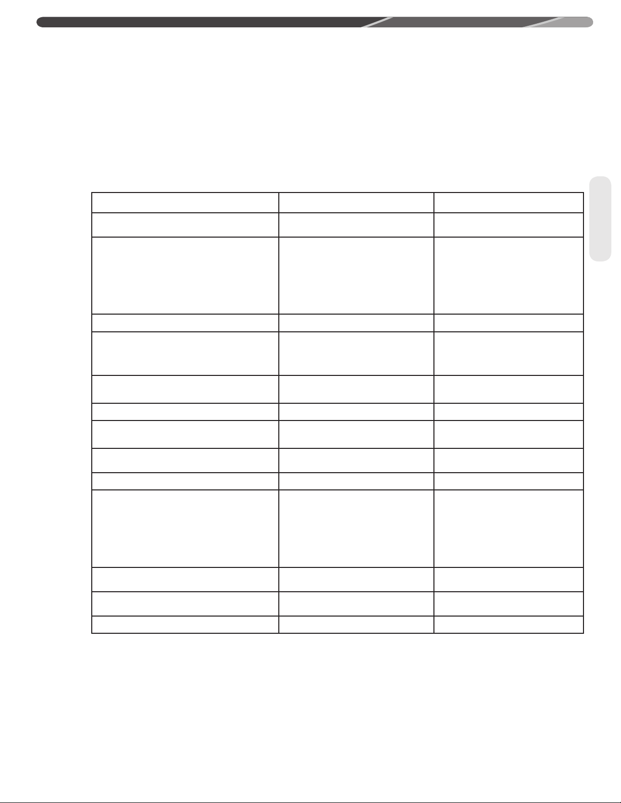
Horizontal Vent Terminal Location (cont.)
The following chart details the minimal dimensional information needed to determine the proper location of the vent
terminal for direct vent and outdoor tankless water heaters� See corresponding letter reference in the illustration on page
38�
Loading ...
Loading ...
Loading ...