Loading ...
Loading ...
Loading ...
s
!
NOTICE: Installation of the 115 VAC electrical supply circuit to the battery charger is to be done by a certied licensed
electrician in accordance with national and local codes.
a. Verify that Charger/Controller Unit is not connected to power supply source. Remove plastic cover on the bottom of Charger
Controller Unit. Connect the terminals from the control switch cord to the (2) male tab terminals on the Charger/Controller Unit
marked “SWITCH”. Reinstall plastic cover.
b. Verify that all plumbing is complete per instructions.
c. Connect the terminals from the backup pump cord to the terminals from the Charger/Controller Unit cord for the pump being
careful to match the correct polarity.
d. Connect Charger/Controller Unit to the battery. Be certain to connect positive terminal of the Charger/Controller Unit cord
for the battery to the positive post of the battery. Correct polarity is marked on the cord as well as the battery. In case of
reverse connection the Charger/Controller Unit will sound an alarm when 115 VAC power is supplied to the
Charger/Controller Unit.
e. Do not connect this Charger/Controller Unit to the same circuit as is used for the primary pump. The AC outlet used for the
Charger/Controller Unit requires separate 3A, 115 VAC circuit.
f. Verify that all wiring is per instructions. Once all plumbing and electrical connections are complete and veried, plug 115 VAC
power supply cord for the Charger/Controller Unit into a 115 VAC electrical outlet.
g. Press the “test switch” and observe that the 12 VDC pump is running.
h. Review Charger/Controller Operation section.
i. Perform testing per the Sump System Operation Testing Section.
s
!
NOTICE: The Charger/Controller Unit has provisions for connection to auxiliary Class 2 alarm system or phone dialer (not
included). This circuit is normally open and closes when the 12 VDC pump switch circuit closes. Once closed, the circuit
remains closed until “RESET” button is pushed on the Charger/Controller Unit. This circuit requires Class 2 wiring. If used,
route this wiring away from the Charger/Controller Unit power supply cord, battery cord, and pump cord. Follow
manufacturer’s instructions for dialer or alarm system.
Charger/Controller Unit Installation (continued)
s WARNING
!
WARNING
Comply with all national and local electrical and plumbing codes when installing
this unit. Disconnect power from all electrical equipment housed within the sump system before working
on or around the sump pump or battery backup system beginning with 115 VAC powered pumps, level
switches, and charger controllers; followed by DC powered items. Includes all items such as pumps,
level control switches, Charger/Controller Unit, and battery systems.
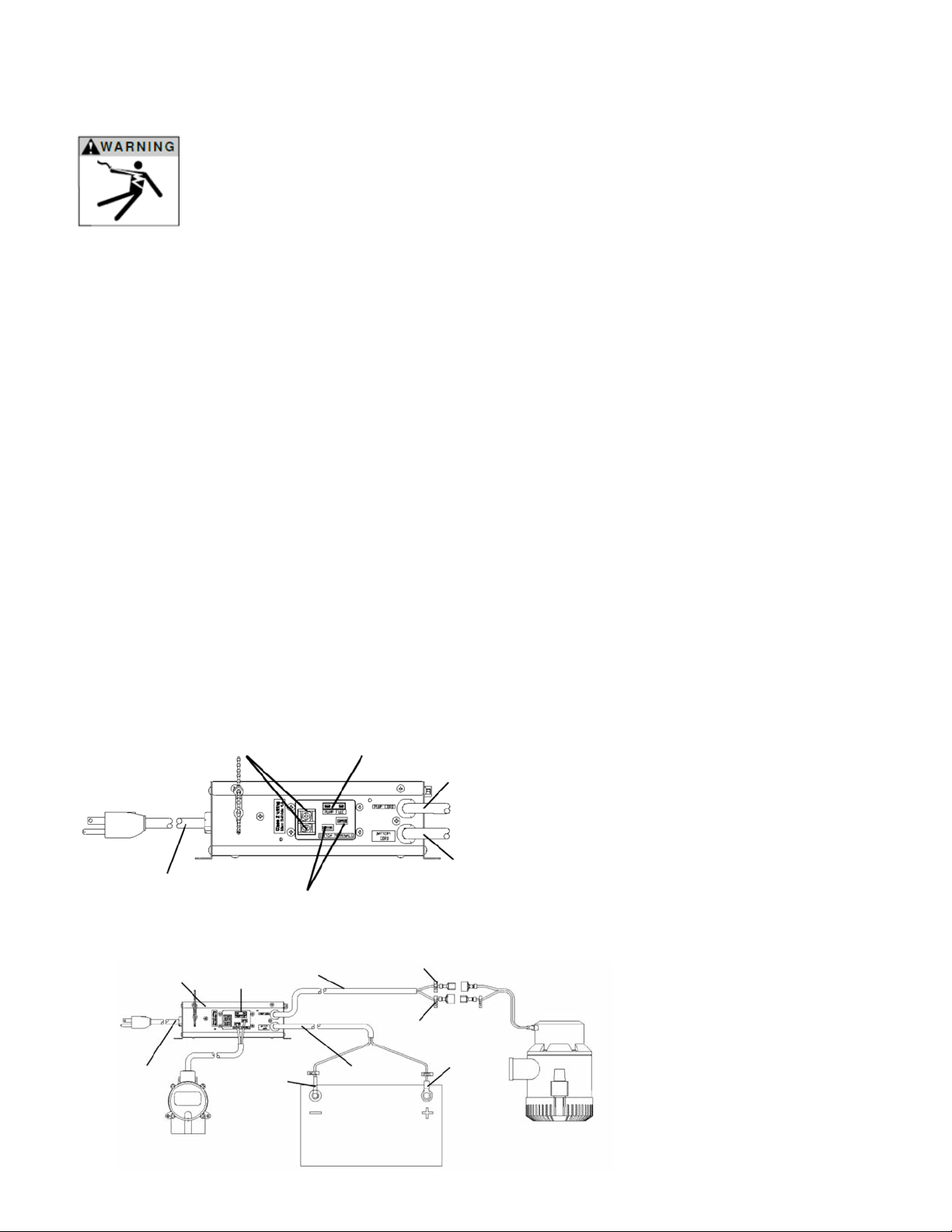
Step 2 – Electrical Connections
Charger/Controller Unit Electrical Connections
Normally Open Circuit
Terminals for Class 2
Alarm or Dialer
Pump Fuse 32 V, 20 Amp
Type ATC
Pump Cord
Battery Cord
Backup Pump Switch Terminals
Charger Controller
Power Supply Cord
Pump Cord
Pump
Fuse
Charger
Controller Unit
Charger
Controller
Power Supply
Cord
Pump Negative Lead
Battery
Positive
Lead
Battery
Negative
Lead
Pump
Positive
Lead
12 VDC Deep
Cycle Battery
Backup Pump
Control Switch
12 VDC
Backup
Pump
Wiring Diagram
Figure 8
Figure 9
17
Loading ...
Loading ...
Loading ...