Loading ...
Loading ...
Loading ...
Charger/Controller Unit Installation (continued)
Step 1 – Mounting the Charger/Controller Unit
s
!
NOTICE: Do not expose the charger to excessive moisture. Install charger in a dry location. Indoor use only.
a. Complete all plumbing, pump installation and pump control switch installation before installing the Charger/Controller Unit
and before beginning work on the electrical connections to the Charger/Controller Unit or the battery.
b. Charger/Controller Unit is designed to be installed on the wall in a visible location. The LED lights on the front of the charger
as well as the switches on the face of the unit should be accessible and clearly visible.
c. Select a location for the Charger/Controller Unit and the battery relative to the sump basin such that all the provided wiring
will reach their respective connections with some slack remaining in the wiring. Locate the Charger/Controller Unit as far
away from battery as the provided wiring permits. Charger/Controller Unit should not be installed directly over the battery.
Gases from the battery will corrode and damage the Charger/Controller Unit. Battery should be positioned away from the
wall to allow adequate ventilation of any fumes that are given o during charging.
d. Use the Charger/Controller Unit’s mounting holes to mark location on the wall for the included anchors and
mounting screws.
e. Install the Charger/Controller Unit on the wall using the included anchors and mounting screws, if suitable. Installer to
conrm suitability of the mounting surface, method, and hardware.
s WARNING
!
CAUTION
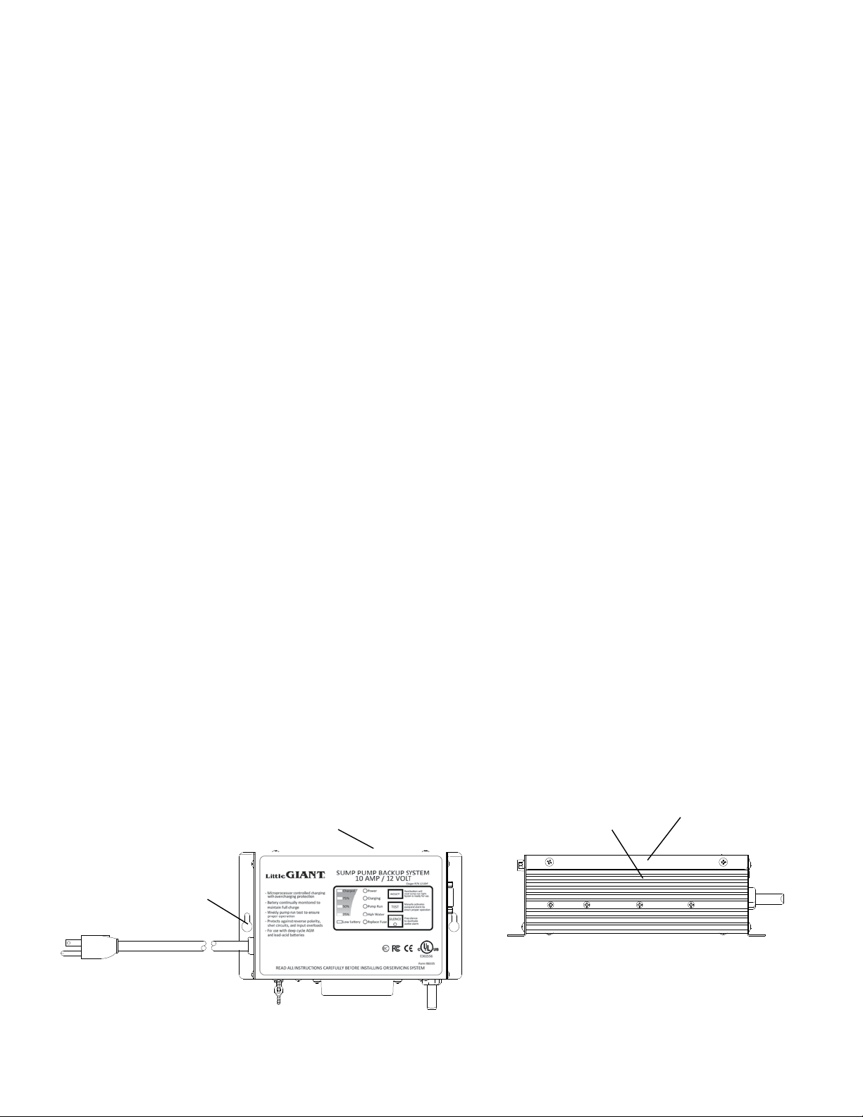
The long ribs on the Charger/Controller Unit should be on top and the cords exit downward when the
Charger/Controller Unit is installed on the wall. The long ribs are heat sinks and may become hot in normal operation. Do
not allow these surfaces to become covered in combustible materials and do not touch these during normal operation. All
combustible materials should be kept away from the hot surfaces of the Charger/Controller Unit, and the Charger/Controller
Unit should be well away from other sources of heat such as space heaters, radiators, boilers, furnace etc.
s WARNING
!
CAUTION
The Charger/Controller Unit has a 115 VAC power supply cord, a cord for connecting to the battery,
and a cord for connecting to the pump cord. If any of the cords are damaged, or the Charger/Controller Unit itself becomes
damaged, immediately un-plug the Charger/Controller Unit and remove it from service. Always disconnect 115 VAC power
supply cord before doing any service of the product and allow the Charger/Controller Unit to cool. Disconnect 115 VAC before
disconnecting battery leads.
s WARNING
!
CAUTION
Power is being supplied to the 12 VDC backup pump when the “Water High” indicator is on or the test
button is held down. Do not disconnect the pump cable while power is going to the 12 VDC backup pump.
s WARNING
!
CAUTION
There are no serviceable parts inside the Charger/Controller Unit body. Do not open or attempt any
repairs inside the Charger/Controller Unit body. Hazardous voltage exists inside the enclosure.
s WARNING
!
CAUTION
Do not try to charge non rechargeable batteries.
s
!
NOTICE: 12 VDC backup pump fuse is located on the bottom of the charger. Replacement fuse should be automotive type
32 V, 20A type ATC.
Charger Control Unit
Mounting Holes
Heat Sink Ribs
HOT! Do Not Touch!
Charger Control
Unit Top View
Figure 6 Figure 7
16
Loading ...
Loading ...
Loading ...