
Owner’s Manual
Sump Pump Battery
Backup Systems

s WARNING
!
Before Getting Started
Read and follow safety instructions. Refer to product data plate(s) for additional operating instructions and specications.
s CAUTION
!
s WARNING
!
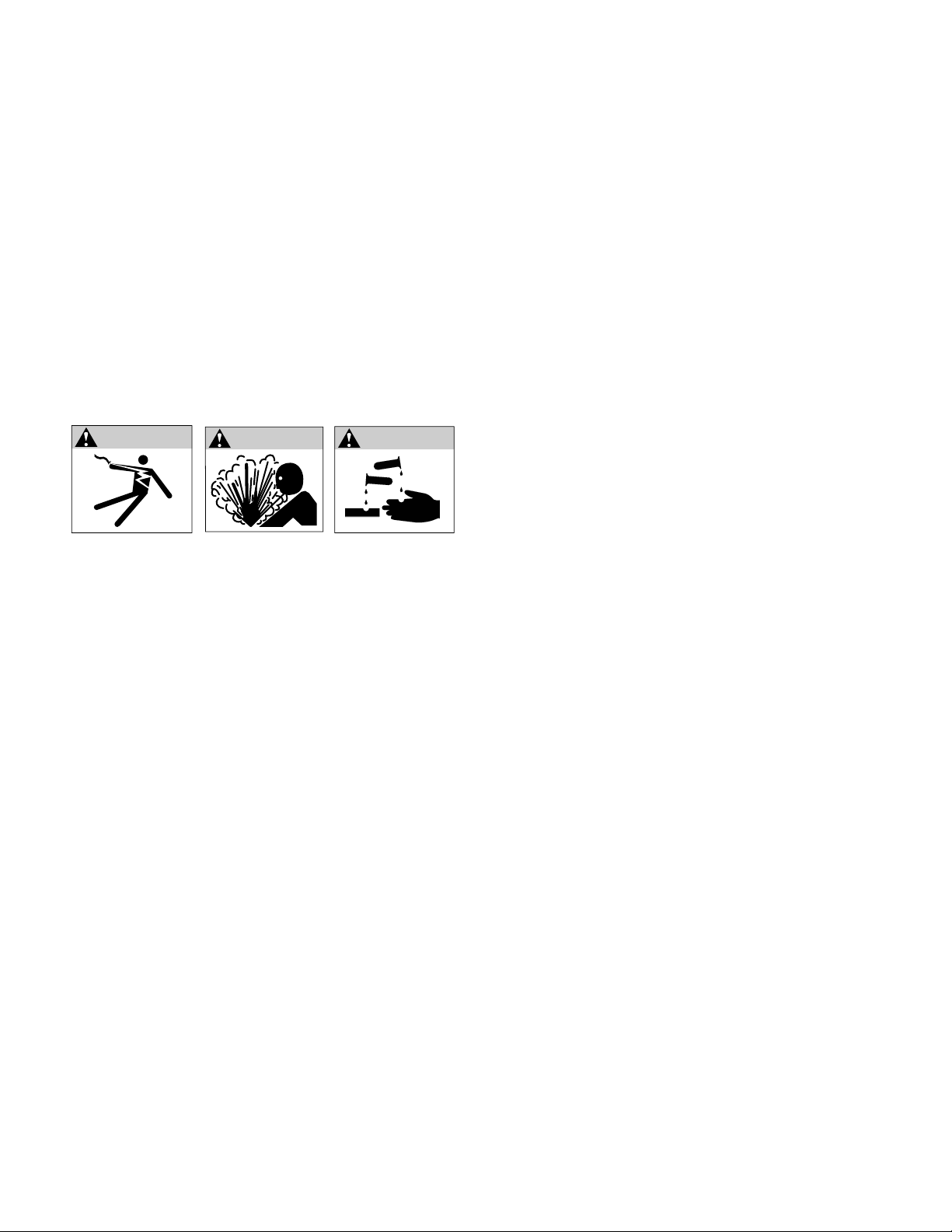
This is the safety alert symbol. When you see this symbol on your pump or in this manual, look for one of the following
signal words and be alert to the potential for personal injury or property damage if ignored:
s WARNING
!
DANGER
s WARNING
!
NOTICE
warns about hazards that will cause serious personal injury, death or major property
damage if ignored.
warns about hazards that can cause serious personal injury, death or major property
damage if ignored.
warns about hazards that will or can cause minor personal injury or major property
damage if ignored.
indicates special instructions which are important but not related to hazards. Carefully read and
follow all safety instructions in this manual and on pump.
s WARNING RISK OF ELECTRIC SHOCK - This pump is supplied with a grounding conductor and grounding type
attachment plug. To reduce risk of electric shock, be certain that it is connected only to a properly grounded,
grounding-type receptacle. Disconnect power before working on or around the sump pump or battery backup system.
This equipment should be installed by technically qualied personnel. Failure to install in compliance with national, local
electrical, and within Franklin Electric recommendations may result in electrical shock or re hazard, unsatisfactory
performance, or equipment failure. Installation information is available through pump manufacturers and distributors, or
directly from Franklin Electric at our toll free number 1-800-701-7894.
This equipment must not be used by children or persons with reduced physical, sensory or mental abilities, or lacking in
experience and expertise, unless supervised or instructed. Children may not use the equipment, nor may they play with
the equipment or in the immediate vicinity.
If the power cord is damaged, it must only be replaced by qualied personnel.
• Keep work area clean, well-lit, and uncluttered.
• Keep safety labels clean and in good condition.
• Wear safety glasses while installing or performing maintenance on pump.
• Do not run pump dry. Fill pump with water before starting or pump will be damaged.
• Make sure all ELECTRICAL POWER IS OFF before connecting any electrical wires. Wire sump pump system for
correct voltages. Follow all pump wiring instructions provided in the “Wiring” section of this manual.
s CAUTION
!
• Keep work area clean, well-lit, and uncluttered.
• Keep safety labels clean and in good condition.
• Wear safety glasses while installing or performing maintenance on pump.
• Do not run pump dry. Fill pump with water before starting or pump will be damaged.
• Make sure all ELECTRICAL POWER IS OFF before connecting any electrical wires. Wire sump pump system
for correct voltages. Follow all pump wiring instructions provided in the “System Wiring Diagram” and “Electrical
Connections” sections of this manual.
!
2
s WARNING
!

Table of Contents
Getting Started ...................................................................................4
Specications ....................................................................................5
Pump Performance Curves..........................................................................7
Installation of Backup System on Common Discharge (Models SPBS-10HF and SPBS-12HF)....................8
Installation of Backup System on Separate Discharge (Models SPBS-10HF and SPBS-12HF). ..................11
Installation of Pre-assembled Backup System on Common Discharge
(Models SPBS-10HF-6 and SPBS-12HF-10) ...........................................................14
Charger/Controller Unit Installation...............................................................15
Electrical Connections .........................................................................17
System Wiring Diagram ........................................................................17
Charger/Controller Unit Operation ...................................................................18
Sump System Operation Testing ....................................................................19
System Maintenance..............................................................................20
System Troubleshooting ...........................................................................21
Limited Warranty .................................................................................22
3
4
Getting Started
This owner’s manual provides you with the information required to safely own and operate your Little Giant battery backup
system. Retain these instructions for future reference. The Little Giant battery backup system you have purchased is of the
highest quality workmanship and material, and has been engineered to give you long and reliable service. Little Giant pumps are
carefully tested, inspected, and packaged to ensure safe delivery and operation. Please examine your pump carefully to ensure
that no damage occurred during shipment. If damage has occurred, please contact the place of purchase. They will assist you in
replacement or repair, if required.
s WARNING
!
WARNING
READ THESE INSTRUCTIONS CAREFULLY BEFORE ATTEMPTING TO INSTALL, OPERATE, OR
SERVICE YOUR LITTLE GIANT PUMP. KNOW THE PUMP’S APPLICATION, LIMITATIONS, AND POTENTIAL HAZARDS.
PROTECT YOURSELF AND OTHERS BY OBSERVING ALL SAFETY INFORMATION. FAILURE TO COMPLY WITH THESE
INSTRUCTIONS COULD RESULT IN PERSONAL INJURY AND/OR PROPERTY DAMAGE!
Description
The battery backup system is designed as a backup to work in conjunction with a primary sump pump providing operation during
temporary power outages or if the primary pump fails to function due to a blown fuse, tripped circuit breaker, defective switch,
debris clogging the primary pump, or for any other reason.
Hazardous voltage.
Can shock, burn, or
cause death.
Ground pump before
connecting to power
supply. Disconnect
power before working
on pump, motor
or tank.
WARNING
DANGER
WARNING
s
!
DANGER
Do not use to pump ammable or explosive uids such as gasoline, fuel oil, kerosene, etc. Do not use in
explosive atmospheres. Pump should only be used with liquids compatible with pump component materials. Do not handle pump
or Charger/Controller Unit with wet hands or when standing on a wet or damp surface, or in water.
s WARNING
!
WARNING
To reduce risk of electric shock which can result in personal injury, death or major property damage if
ignored, be certain that the 115 VAC pump and the Charger/Controller Unit are connected to outlets protected by ground fault
circuit interrupters (GFCI). Comply with all national and local electrical and plumbing codes when installing this unit. Do not use
the same 115 VAC outlet for primary pump and Battery Charger/Controller Unit. Do not use extension cord.
s WARNING
!
WARNING
A spark near the battery may cause an explosion. Always unplug Charger/Controller Unit prior to
making connections to or disconnections from the battery. Take care to prevent accidental shorting across battery terminals
during handling. Do not leave battery uncovered. Attach or strap cover security on battery box when completing installation.
s WARNING
!
CAUTION
The battery required to operate this unit contains acid and proper precautions must be taken when
handling. Refer to battery manufacturer’s safety guidelines. Failure to use proper personal protective equipment or electrical
caution can result in hazards that will or can cause personal injury or major property damage if ignored.
s WARNING
!
CAUTION
If a Carbon Monoxide (CO) sensor is installed near the battery backup system, battery, or Charger/
Controller Unit, nuisance or false alarms could result. CO detectors should be a minimum of 15 feet from the systems. Refer to
the manufacturer of CO detector for additional instructions or information.
s
!
NOTICE
The Charger/Controller Unit emits an audible alarm when running the 12 VDC backup pump. An additional
(not supplied in this kit) audible high water alarm on the sump system is recommended in any installations where property
damage and/or personal injury might result from an inoperative sump system due to long term power outages, discharge line
blockage, or any other reason.

Specications
Item Number Model Number
506406 SPBS-10HF
Charging Unit
Model Number Volts Hz
Max Input Amps at
115 VAC
Max Output
Amps at 12 VDC
Watts Cord (ft) Weight (lb)
Battery
Leads (ft)
Item Number
106469 1210HF 115 VAC 60 3 10 345 6 5 6
Backup Pump
Switch
Model Number Volts Hz Switch On Level Switch O Level Watts Cord (ft) Weight (lb)
Battery
Leads (ft)
Item Number
105601 RS-12 12 VDC - 13.5" 9" - 9 0.5 -
Backup Pump
Model Number Volts Hz
Amps
Watts Cord (ft) Weight (lb)
Battery
Leads (ft)
Item Number FLA Start
106963 2500 12 VDC - 14 32 168 6 6 -
5
Item Number Model Number
506407 SPBS-12HF
Charging Unit
Model Number Volts Hz
Max Input Amps at
115 VAC
Max Output
Amps at 12 VDC
Watts Cord (ft) Weight (lb)
Battery
Leads (ft)
Item Number
106486 1212HF 115 VAC 60 3 12 345 6 5 6
Backup Pump
Switch
Model Number Volts Hz Switch On Level Switch O Level Watts Cord (ft) Weight (lb)
Battery
Leads (ft)
Item Number
105601 RS-12 12 VDC - 13.5" 9" - 9 0.5 -
Backup Pump
Model Number Volts Hz
Amps
Watts Cord (ft) Weight (lb)
Battery
Leads (ft)
Item Number FLA Start
106961 3360 12 VDC - 15 32 180 6 6 -

Specications
Item Number Model Number
506410 SPBS-12HF-10
Charging Unit
Model Number Volts Hz
Max Input Amps at
115 VAC
Max Output
Amps at 12 VDC
Watts Cord (ft) Weight (lb)
Battery
Leads (ft)
Item Number
106486 1212HF 115 VAC 60 3 12 345 6 5 6
Backup Pump
Model Number Volts Hz
Amps
Watts Cord (ft) Weight (lb)
Battery
Leads (ft)
Item Number FLA Start
106961 3360 12 VDC - 15 32 180 6 6 -
Backup Pump
Switch
Model Number Volts Hz Switch On Level Switch O Level Watts Cord (ft) Weight (lb)
Battery
Leads (ft)
Item Number
105601 RS-12 12 VDC - 13.5" 9" - 9 0.5 -
Primary Pump
Model Number Volts Hz Hz Amps - FLA Watts Cord (ft) Weight (lb)
Battery
Leads (ft)
Item Number
510803 10EC–CIA-SFS 115 VAC 60 1/2 6.5 750 10 26 -
Item Number Model Number
506411 SPBS-10HF-6
Charging Unit
Item Number Model Number Volts Hz
Max Input Amps at
115 VAC
Max Output
Amps at 12 VDC
Watts Cord (ft) Weight (lb)
Battery
Leads (ft)
106469 1210HF 115 VAC 60 3 10 345 6 5 6
Backup Pump AMPS
Item Number Model Number Volts Hz FLA Start Watts Cord (ft) Weight (lb)
Battery
Leads (ft)
106963 2500 12 VDC - 14 32 168 6 6 -
Backup Pump
Switch
Item Number Model Number Volts Hz Switch On Level Switch O Level Watts Cord (ft) Weight (lb)
Battery
Leads (ft)
105601 RS-12 12 VDC - 13.5" 9" - 9 0.5 -
Primary Pump
Item Number Model Number Volts Hz Horsepower (HP) Amps - FLA Watts Cord (ft) Weight (lb)
Battery
Leads (ft)
506807 6EC-CIA-SFS 115 VAC 60 1/3 5 600 10 30 -
6

HEAD - METERS
FLOW - LITERS/MINUTE
HEAD - FEET
FLOW - GALLONS/MINUTE
0
1.5
3
4.5
6
7.5
0 30 60 90 120 150 180
0
5
10
15
20
25
0 10 20 30 40 50
HEAD - METERS
FLOW - LITERS/MINUTE
HEAD - FEET
FLOW - GALLONS/MINUTE
0
1.5
3
4.5
6
7.5
0 20 40 60 80 100 120 140 160
0
5
10
15
20
25
0 10 20 30 40 50
Pump Performance Curves
2500 12 VDC (106963) 3360 12 VDC (106961)
HEAD - METERS
FLOW - LITERS/MINUTE
HEAD - FEET
FLOW - GALLONS/MINUTE
0
1
2
3
4
5
6
7
8
9
0 50 100 150 200
0
5
10
15
20
25
30
0 10 20 30 40 50 60
6EC-CIA-SFS (506807)
HEAD - METERS
FLOW - LITERS/MINUTE
HEAD - FEET
FLOW - GALLONS/MINUTE
0
3
6
9
12
0 40 80 120 160 200 240
0
10
20
30
40
0 10 20 30 40 50 60 70
10EC-CIA-SFS (510803)
7
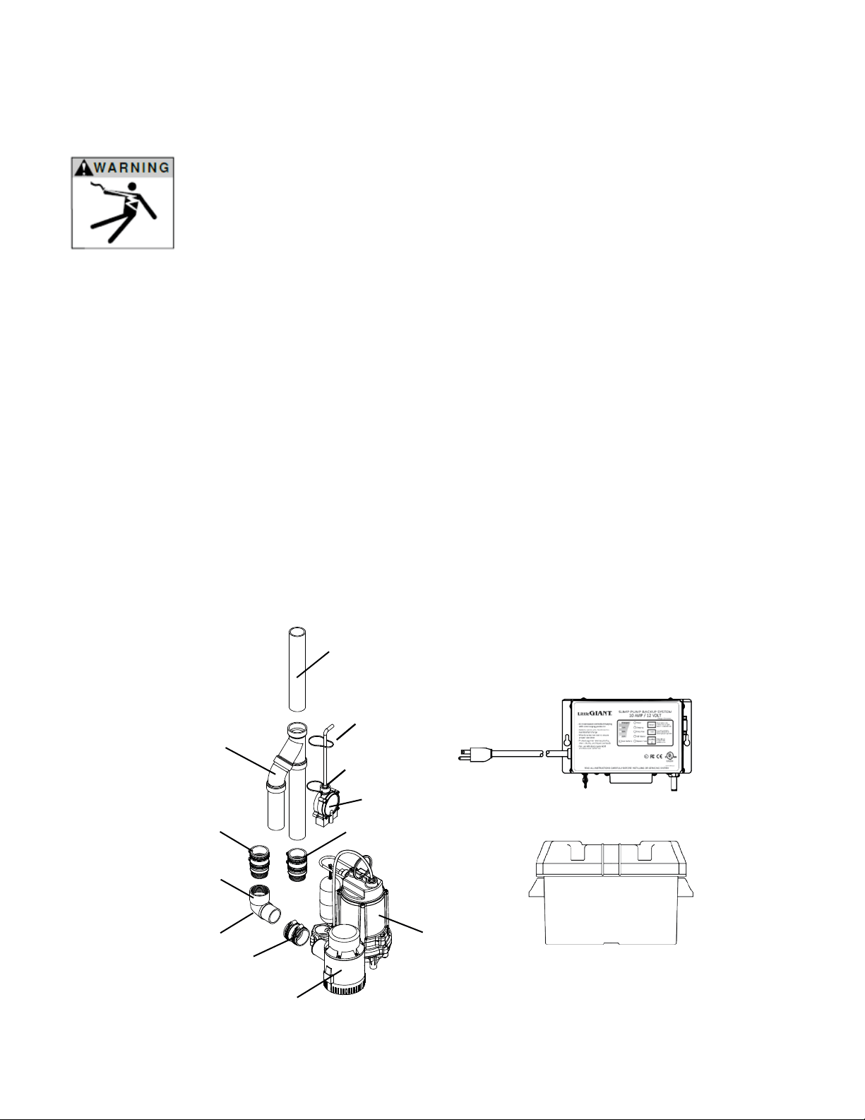
Figure 1
Installation of a Backup System on
a Common Discharge
s WARNING
!
WARNING
Comply with all national and local electrical and plumbing codes when
installing this unit. Disconnect power from all electrical equipment housed within the sump system
before working on or around the sump pump or battery backup system beginning with 115 VAC
powered pumps, level switches, and charger controllers; followed by DC powered items. Includes all
items such as pumps, level control switches, Charger/Controller Unit, and battery systems.
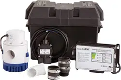
Included in the SPBS-10HF and SPBS-12HF Kits:
1. Battery charger/controller
2. Battery case (battery not included)
3. (1) 1-½" street elbow near 12 VDC pump
4. Flexible coupling from 12 VDC pump discharge
5. Check valve for 12 VDC pump
6. Switch to control 12 VDC pump
7. 12 VDC backup pump
8. (4) Cable ties
Customer required to purchase separately:
1. 12 VDC deep cycle battery – BCI Group 27, rated 85 – 140Ah, lead-acid or AGM
2. 115 VAC primary pump. Little Giant’s 6EC-CIA-SFS or 10EC-CIA-SFS automatic pump is recommended
3. Check valve for 115 VAC pump
4. 1-½” pipe as needed
5. 1-½” DWV street elbow H-SPG 45 degree
6. 1-½” DWV wye
7. Fittings – as required
(For 12 VDC Backup Systems SPBS-10HF and SPBS-12HF which do not include a 115 V primary sump pump assembly)
Cable Tie (2)
Cable Tie (1)
Backup Pump
Control Switch
Check Valve
(not included)
Primary Pump
(not included)
Backup
Pump
Flexible
Coupling
Air Bleed
Hole
90º Street
Elbow
Check Valve
Discharge Pipe
“WYE” Assembly
(not included)
Common drain pipe from
household plumbing
(not included)
Charger/Controller Unit
Battery Box
Backup System on a Common Discharge
8

s WARNING
!
CAUTION
Reduction of plumbing sizes from what is used for the discharges of the primary 115 VAC pump and 12
VDC pump can result in system underperformance. Discharge piping that is of insucient size can result in premature pump and/
or system operation failure.
Step 1 Step 2 Step 3 Step 4 Step 5 Step 6
s
!
NOTICE: Do not glue any parts until the entire assembly, including primary pump, has been dry-assembled to verify ts.
Fitting plumbing and routing wiring away from control oats will be much easier on a bench rather than working down inside
a sump pit. (Fig. 2)
Step 1
a. Install exible coupling onto 12 VDC pump discharge.
b. Position two hose clamps in the grooved recesses of exible coupling installed on the 12 VDC pump.
c. Tighten the exible coupling’s rst hose clamp connection to securely fasten it to the 12 VDC pump discharge.
d. Leave the hose clamp on the opposite end loose for the next plumbing piece.
Step 2
a. A 3/16" diameter air bleed hole has been drilled in the 90º street elbow that is provided with the kit. (NOTICE: Air
bleed hole must be located between the check valve and the 12 VDC pump to prevent the 12 VDC pump from air-locking.)
The bleed hole is located so that the water ow through it will be at a downward angle to prevent splashing from the basin/pit.
b. Slip 90º street elbow into the exible coupling attached to the 12 VDC pump discharge, and tighten the hose clamp to
secure elbow to the 12 VDC pump’s discharge. (When properly installed the threaded elbow connection of the 90º street
elbow should be facing straight up toward the top of the sump pit).
Step 3
s
!
NOTICE: A check valve is supplied and required for the backup pump’s discharge plumbing. This check valve must be installed
in the discharge plumbing between the backup pump and the wye connection joining the backup pump’s discharge to that of
the primary pump’s discharge.
a. Apply PTFE tape to male threads of provided check valve.
b. Thread PTFE taped end of check valve into 90° elbow.
Step 4
a. Position two hose clamps in the grooved recesses of the exible coupling on the check valve installed in the elbow.
b. Tighten the lower hose clamp to secure the exible coupling to the check valve body.
c. Loosely tighten the upper hose clamp so it does not fall o. This clamp will be used to secure the check valve to the
discharge pipe “wye” assembly.
Step 5
a. Review the discharge plumbing of the 115 VAC primary pump.
s
!
NOTICE: A customer-supplied check valve is required in the discharge plumbing of the 115 VAC primary sump pump.
This check valve must be installed in the discharge plumbing between the primary pump and the wye connection joining the
backup pump’s discharge to that of the primary pump’s discharge. A 3/16" diameter air bleed hole must be located between
the check valve and the 115 VAC pump to prevent the 115 VAC pump from air-locking. Locate the bleed hole so that the water
ow through it will be at a downward angle to prevent splashing from the basin/pit.
b. The 1-1/2" PVC pipe used in making the discharge pipe “wye” assembly must be cut so as to ensure that both the 115 VAC
primary pump and the 12 VDC backup pump rest at on the oor of the sump basin when the plumbing is completely
assembled and to align connection to the drain piping from the home. Dry-t the assembly to conrm prior to gluing
(see Figure 1).
c. Once dry-t conrms that both pumps rest at on the sump basin oor and the wye Assembly piping aligns with drain piping
from the home, secure all connections by applying approved waterproof adhesive to all necessary joints and conrm that all
exible coupling hose clamps are fully engaged with plumbing and fully tightened.
Figure 2
Drill 3/16" hole
9

Step 6
a. Cable Ties (1) and (2) will be used to attach the 12 VDC pump control switch housing and power cord to the discharge pipe.
Installing both cable ties to 12 VDC pump control switch is critical for proper operation of 12 VDC pump. (see Figure 1).
b. Thread cable tie (1) through the eyelets on the 12 VDC pump control switch housing.
c. Position the 12 VDC pump control switch on the discharge pipe such that cable tie (1) is 4" to 6" above the “ON” water level
of the 115 VAC primary pump.
d. Tighten cable tie (1) to secure the 12 VDC pump control switch to the discharge pipe.
e. Install cable tie (2) around both the power cord of the 12 VDC pump control switch and the discharge pipe such that the
power cord is securely routed away from any control oats.
f. Use electrical tape to further secure the power cord of the 12 VDC pump control switch to the discharge pipe.
s
!
NOTICE: RS-12 switch cord contains a breather tube. Be sure switch cord is not pinched so that breather tube is obstructed.
Non-restrictive air ow in breather tube is required for proper RS-12 operation.
s
!
NOTICE: For proper pump operation the exit point of all drain piping from the home must be lower, or sloping away, from the
discharge plumbing’s highest point. Improper water drainage can allow freezing within the line leading to system or component
damage or failure.
s WARNING
!
CAUTION
Ensure all hose clamp connections and threaded connections are tight, and that all plumbing slip t
connections are properly glued prior to starting the sump pump system. Failure to do so can result in damage to pump system
and/or cause property damage due to ooding.
s WARNING
!
CAUTION
Do not install or store the pump where it will be exposed to the weather or to temperatures below freezing
or damage to the pump will occur.
10

Installation of a Backup System
on a Separate Discharge
s WARNING
!
WARNING
Comply with all national and local electrical and plumbing codes when
installing this unit. Disconnect power from all electrical equipment housed within the sump system
before working on or around the sump pump or battery backup system beginning with 115 VAC
powered pumps, level switches, and charger controllers; followed by DC powered items. Includes all
items such as pumps, level control switches, Charger/Controller Unit, and battery systems.
Included in the SPBS-10 and SPBS-12 Kits:
1. Battery charger/controller
2. Battery case (battery not included)
3. (1) 1-½" 90° street elbow near 12 VDC pump
4. Flexible coupling from 12 VDC pump discharge
5. Check valve for 12 VDC pump
6. Switch to control 12 VDC pump
7. 12 VDC backup pump
8. (4) Cable ties
Customer required to purchase separately:
1. 12 VDC deep cycle battery – BCI Group 27, rated 85 – 140Ah, lead-acid or AGM
2. 115 VAC primary pump. Little Giant’s 6EC-CIA-SFS or 10EC-CIA-SFS automatic pump is recommended
3. Check valve for 115 VAC pump
4. 1-½" pipe as needed
5. Fittings – As required
(For 12 VDC Backup Systems SPBS-10HF and SPBS-12HF which do not include a 115 V primary sump pump assembly)
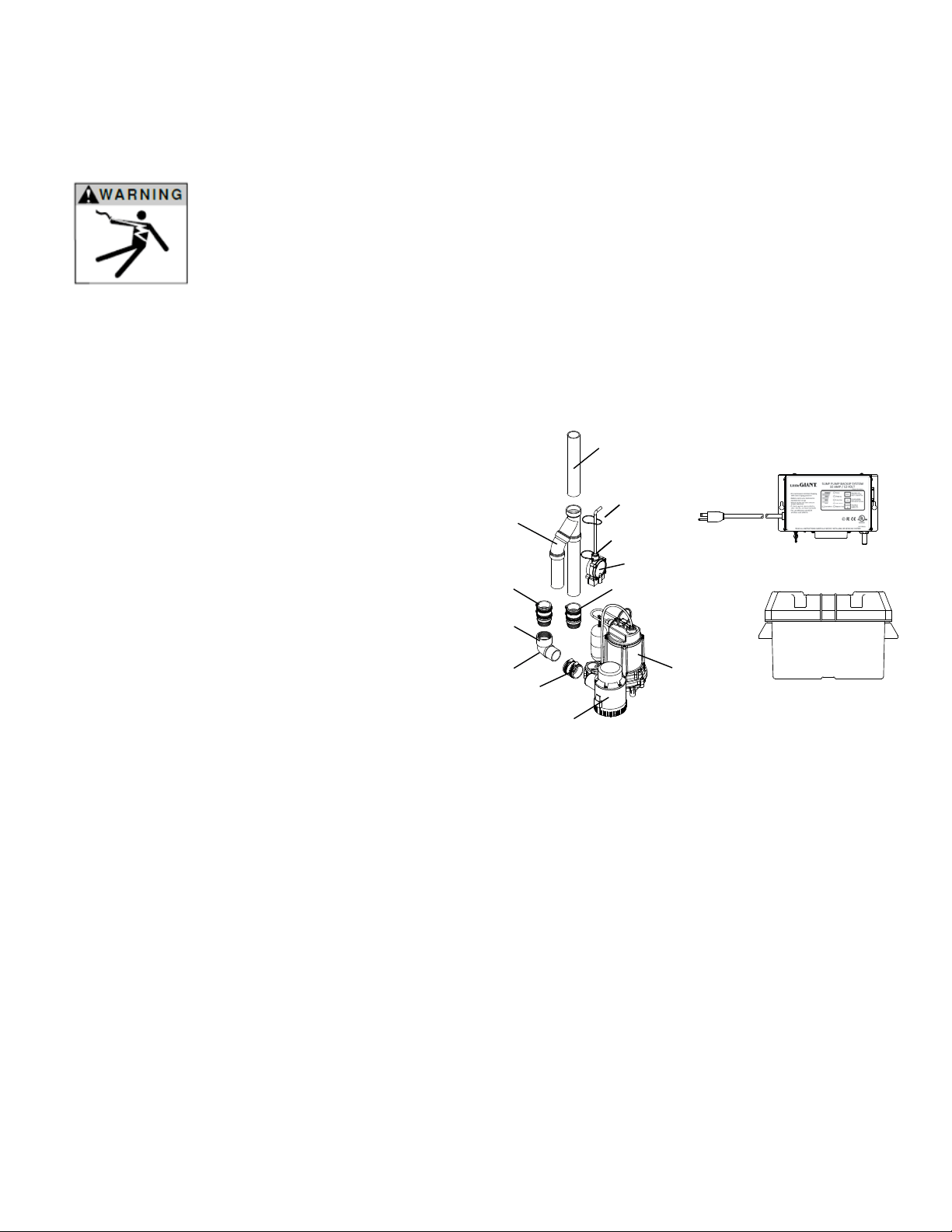
Figure 3
Cable Tie (2)
Cable Tie (1)
Backup Pump
Control Switch
Check Valve
(not included)
Backup
Pump
Flexible
Coupling
Air Bleed
Hole
90º Street
Elbow
Check Valve
Backup drain pipe from
household plumbing
(not included)
Charger/Controller Unit
Battery Box
Primary Pump
(not included)
Primary drain pipe from
household plumbing
(not included)
11

s WARNING
!
CAUTION
Reduction of plumbing sizes from what is used for the discharges of the primary 115 VAC pump and 12
VDC pump can result in system under performance. Discharge piping that is of insucient size can result in premature pump
and/or system operation failure.
Step 1 Step 2 Step 3 Step 4 Step 5 Step 6
s
!
NOTICE: Do not glue any parts until the entire assembly, including primary pump, has been dry-assembled to verify ts.
Fitting plumbing and routing wiring away from control oats will be much easier on a bench rather than working down inside a
sump pit. (Fig. 4)
Step 1
a. Install exible coupling onto 12 VDC pump discharge.
b. Position two hose clamps in the grooved recesses of exible coupling installed on the 12 VDC pump.
c. Tighten the exible coupling’s rst hose clamp connection to securely fasten it to the 12 VDC pump discharge.
d. Leave the hose clamp on the opposite end loose for the next plumbing piece.
Step 2
a. A 3/16" diameter air bleed hole has been drilled in the 90º street elbow that is provided with the kit. (NOTICE: Air bleed
hole must be located between the check valve and the 12 VDC pump to prevent the 12 VDC pump from air-locking.) The bleed
hole is located so that the water ow through it will be at a downward angle to prevent splashing from the basin/pit.
b. Slip 90º street elbow into the exible coupling attached to the 12 VDC pump discharge, and tighten the hose clamp to
secure elbow to the 12 VDC pump’s discharge. (When properly installed the threaded elbow connection of the 90º street
elbow should be facing straight up toward the top of the sump pit).
Step 3
s
!
NOTICE: A check valve is supplied and required for the backup pump’s discharge plumbing. This check valve must be installed
in the discharge plumbing between the backup pump and the connection joining the backup pump’s discharge to the separate
backup pump drain piping from the home.
a. Apply PTFE tape to male threads of provided check valve.
b. Thread PTFE taped end of check valve into 90° elbow.
Step 4
a. Position two hose clamps in the grooved recesses of the exible coupling on the check valve installed in the elbow.
b. Tighten the lower hose clamp to secure the exible coupling to the check valve body.
c. Loosely tighten the upper hose clamp so it does not fall o. This clamp will be used to secure the check valve to the
separate backup pump drain piping from the home.
Step 5
a. Review the discharge plumbing of the 115 VAC primary pump.
s
!
NOTICE: A customer-supplied check valve is required in the discharge plumbing of the 115 VAC primary sump pump. This
check valve must be installed in the discharge plumbing between the primary pump and the separate primary pump drain
piping from the home. A 3/16" diameter air bleed hole must be located between the check valve and the 115 VAC pump to
prevent the 115 VAC pump from air-locking. Locate the bleed hole so that the water ow through it will be at a downward angle
to prevent splashing from the basin/pit.
b. The 1-1/2" PVC pipe used in making the separate backup pump drain piping from the home must be cut so as to ensure that
the 12 VDC backup pump rests at on the oor of the sump basin when the plumbing is completed. Dry-t the assembly to
conrm prior to gluing (see Figure 4).
c. Once dry-t conrms that the 12 VDC backup pump rests at on the sump basin oor and aligns with the separate backup
pump drain piping from the home, secure all connections by applying approved waterproof adhesive to all necessary joints and
conrm that all exible coupling hose clamps are fully engaged with plumbing and fully tightened.
Figure 4
Drill 3/16" hole
12

Step 6
a. Cable ties (1) and (2) will be used to attach the 12 VDC pump control switch housing and power cord to the discharge pipe.
Installing both cable ties to 12 VDC pump control switch is critical for proper operation of 12 VDC pump. (See Figure 3).
b. Thread cable tie (1) through the eyelets on the 12 VDC pump control switch housing.
c. Position the 12 VDC pump control switch on the discharge pipe such that cable tie (1) is 4" to 6" above the “ON” water level of
the 115 VAC primary pump.
d. Tighten cable tie (1) to secure the 12 VDC pump control switch to the discharge pipe.
e. Install Cable Tie (2) around both the power cord of the 12 VDC pump control switch and the discharge pipe such that the power
cord is securely routed away from any control oats.
f. Use electrical tape to further secure the power cord of the 12 VDC pump control switch to the discharge pipe.
s
!
NOTICE: RS-12 switch cord contains a breather tube. Be sure switch cord is not pinched so that breather tube is obstructed.
Non-restrictive air ow in breather tube is required for proper RS-12 operation.
s
!
NOTICE: For proper pump operation the exit point of all drain piping from the home must be lower, or sloping away, from the
discharge plumbing’s highest point. Improper water drainage can allow freezing within the line leading to system or component
damage or failure.
s WARNING
!
CAUTION
Ensure all hose clamp connections and threaded connections are tight, and that all plumbing slip t
connections are properly glued prior to starting the sump pump system. Failure to do so can result in damage to pump system
and/or cause property damage due to ooding.
s WARNING
!
CAUTION
Do not install or store the pump where it will be exposed to the weather or to temperatures below freezing
or damage to the pump will occur.
13
Installation of Pre-assembled Backup
System on a Common Discharge
(For 12 VDC Backup Systems SPBS-10HF-6 and SPBS-12HF-10 with included 115 VAC Primary Pump)
s WARNING
!
WARNING
Comply with all national and local electrical and plumbing codes when
installing this unit. Disconnect power from all electrical equipment housed within the sump system
before working on or around the sump pump or battery backup system beginning with 115 VAC
powered pumps, level switches, and charger controllers; followed by DC powered items. Includes all
items such as pumps, level control switches, Charger/Controller Unit, and battery systems.
s WARNING
!
CAUTION
Reduction of plumbing sizes from what is used for the discharges of the primary 115 V and 12 VDC can
result in system under performance. Discharge piping that is of insucient size can result in premature pump and/or system
operation failure.
Included in the SPBS-10HF-6 and SPBS-12HF-10 kits:
1. 12 VDC backup pump
2. 115 VAC primary pump
3. Battery charger/controller
4. Battery case (battery not included)
5. (1) 1-½" street elbow near 12 VDC pump
6. Coupling for 12 VDC pump discharge
7. Check valve for 12 VDC pump
8. Switch to control 12 VDC pump
9. Check valve for 115 VAC pump
10. Discharge pipe “wye” assembly connected to the
12 VDC pump and 115 VAC pump
Customer required to purchase separately:
1. 12 VDC deep cycle battery – BCI Group 27, rated
85 – 140Ah, Lead-acid or AGM
2. Pipe and coupling or check valve (For connection to
drain pipe from household plumbing to discharge
pipe “wye” assembly)
3. Waterproof adhesive for plumbing connections
Figure 5
Cable Tie (2)
Cable Tie (1)
Backup Pump
Control Switch
Check Valve
(not included)
Primary Pump
(not included)
Backup
Pump
Flexible
Coupling
Air Bleed
Hole
90º Street
Elbow
Check Valve
Discharge Pipe
“wye” assembly
(not included)
Common drain pipe from
household plumbing
(not included)
Charger/Controller Unit
Battery Box
Pre-assembled with Common Discharge Pipe “WYE” Assembly
Step 1
a. Remove all debris from the sump basin.
b. Conrm that all exible couplings and hose clamps are properly seated and tight on the PVC plumbing discharge piping that is
part of the sump pump backup system.
c. Place the sump pump backup system into the sump pit/basin. Support both pumps as the assembly is lowered into the
basin. Do not use the PVC plumbing as a handle during this process as the connections might come loose.
d. The connection from the discharge pipe “wye” assembly to the drain piping from the home must be made so as to ensure
that both the 115 VAC primary pump and the 12 VDC backup pump rest at on the oor of the sump basin when the plumbing
is completely assembled and to align connection to the drain piping from the home. Dry-t the assembly to conrm prior
to gluing (see Figure 5).
e. Once dry-t conrms that both pumps rest at on the sump basin oor and the wye assembly piping aligns with drain piping
from the home, secure all connections by applying approved waterproof adhesive to all necessary joints and conrm that all
exible coupling hose clamps are fully engaged with plumbing and fully tightened.
s WARNING
!
CAUTION
For proper pump operation the exit point of all drain piping from the home must be lower or sloping away,
from the discharge plumbing’s highest point. Improper water drainage can allow freezing within the line leading to system or
component damage or failure.
s WARNING
!
CAUTION
Ensure all hose clamp connections and threaded connections are tight and that all plumbing slip t
connections are properly glued prior to starting the sump pump system. Failure to do so can result in damage to pump system
and/or cause property damage due to ooding.
s WARNING
!
CAUTION
Do not install or store the pump where it will be exposed to the weather or to temperatures below freezing
or damage to the pump will occur.
14
Charger/Controller Electrical Ratings:
Input: 120 VAC, 3 Amp
Output (Maximum Charging Current):
• Model 1210HF: 12 VDC, 10 Amps
• Model 1212HF: 12VDC, 12 Amps
Use only with 12 VDC deep cycle battery rated 85 – 140Ah, lead-acid or AGM
s WARNING
!
WARNING
Do not use in explosive atmospheres. Do not handle Charger/Controller Unit with wet hands or when
standing on a wet or damp surface, or in water.
s WARNING
!
WARNING
To reduce risk of electric shock which can result in personal injury, death or major property damage if
ignored, be certain that the 115 VAC pump and the Charger/Controller Unit are connected to outlets protected by ground fault
circuit interrupters (GFCI). Comply with all national and local electrical and plumbing codes when installing this unit. Do not use
the same 115 VAC outlet for primary pump and Battery Charger/Controller Unit. Do not use extension cord.
s WARNING
!
WARNING
A spark near the battery may cause an explosion. Always unplug Charger/Controller Unit prior to
making connections to or disconnections from the battery. Take care to prevent accidental shorting across battery terminals
during handling. Do not leave battery uncovered. Attach or strap cover securely on battery box when completing installation.
s WARNING
!
CAUTION
The battery required to operate this unit contains acid and proper precautions must be taken when
handling. Refer to battery manufacturer’s safety guidelines. Failure to use proper personal protective equipment or electrical
caution can result in hazards that will or can cause personal injury or major property damage if ignored.
s WARNING
!
CAUTION
If a Carbon Monoxide (CO) sensor is installed near the battery backup system, battery, or Charger/
Controller Unit, nuisance or false alarms could result. CO detectors should be a minimum of 15 feet from the systems. Refer to
the manufacturer of CO detector for additional instructions or information.
s WARNING
!
CAUTION
The backup pump relies on a suciently charged battery to operate the pump. The charger is designed
to charge the battery and maintain charge level when the backup pump is not in use.
s
!
NOTICE: The Charger/Controller Unit emits an audible alarm when running the 12 VDC backup pump. An additional (not
supplied in this kit) audible high water alarm on the sump system is recommended in any installations where property damage
and/or personal injury might result from an inoperative sump system due to long term power outages, discharge line blockage,
or any other reason.
Charger/Controller Unit Installation
15
Charger/Controller Unit Installation (continued)
Step 1 – Mounting the Charger/Controller Unit
s
!
NOTICE: Do not expose the charger to excessive moisture. Install charger in a dry location. Indoor use only.
a. Complete all plumbing, pump installation and pump control switch installation before installing the Charger/Controller Unit
and before beginning work on the electrical connections to the Charger/Controller Unit or the battery.
b. Charger/Controller Unit is designed to be installed on the wall in a visible location. The LED lights on the front of the charger
as well as the switches on the face of the unit should be accessible and clearly visible.
c. Select a location for the Charger/Controller Unit and the battery relative to the sump basin such that all the provided wiring
will reach their respective connections with some slack remaining in the wiring. Locate the Charger/Controller Unit as far
away from battery as the provided wiring permits. Charger/Controller Unit should not be installed directly over the battery.
Gases from the battery will corrode and damage the Charger/Controller Unit. Battery should be positioned away from the
wall to allow adequate ventilation of any fumes that are given o during charging.
d. Use the Charger/Controller Unit’s mounting holes to mark location on the wall for the included anchors and
mounting screws.
e. Install the Charger/Controller Unit on the wall using the included anchors and mounting screws, if suitable. Installer to
conrm suitability of the mounting surface, method, and hardware.
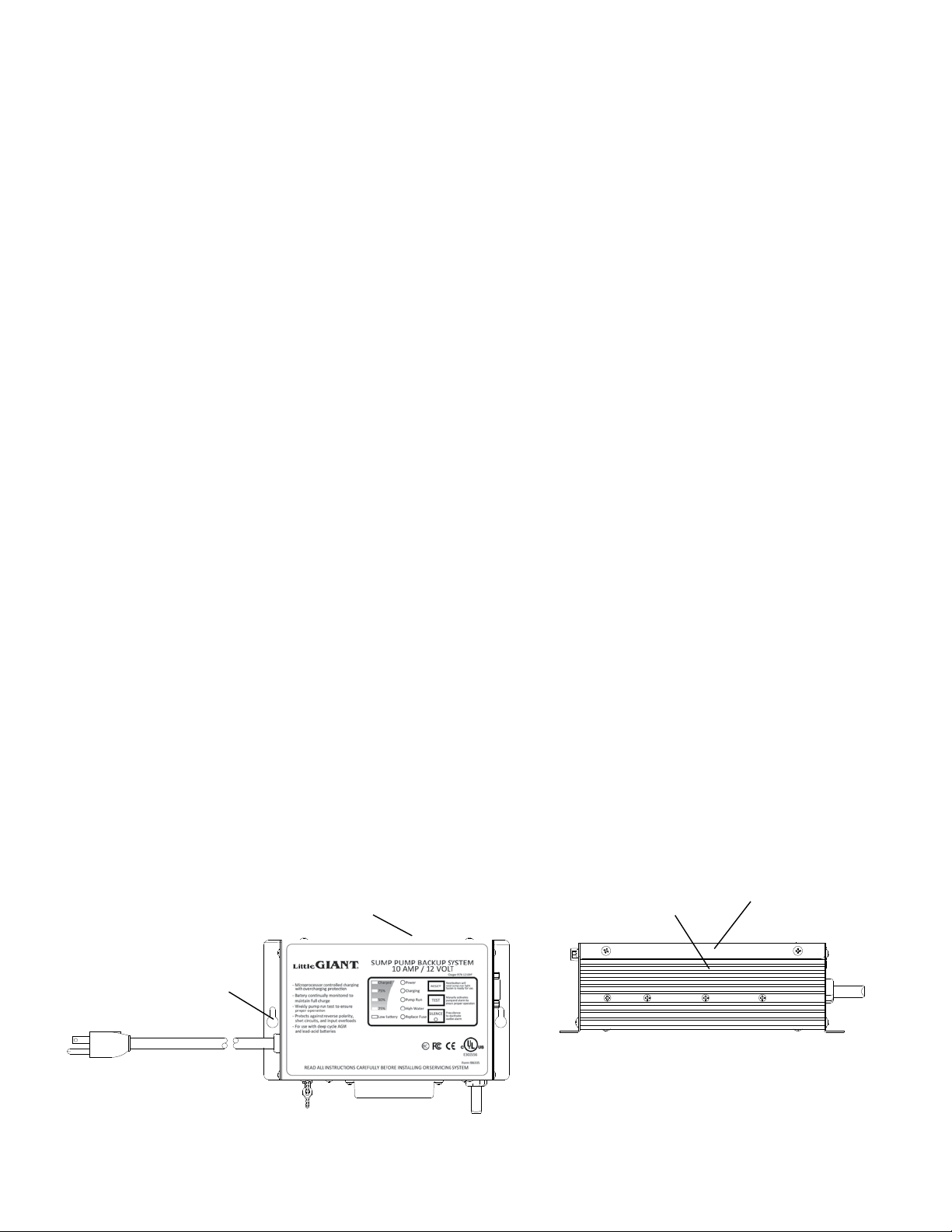
s WARNING
!
CAUTION
The long ribs on the Charger/Controller Unit should be on top and the cords exit downward when the
Charger/Controller Unit is installed on the wall. The long ribs are heat sinks and may become hot in normal operation. Do
not allow these surfaces to become covered in combustible materials and do not touch these during normal operation. All
combustible materials should be kept away from the hot surfaces of the Charger/Controller Unit, and the Charger/Controller
Unit should be well away from other sources of heat such as space heaters, radiators, boilers, furnace etc.
s WARNING
!
CAUTION
The Charger/Controller Unit has a 115 VAC power supply cord, a cord for connecting to the battery,
and a cord for connecting to the pump cord. If any of the cords are damaged, or the Charger/Controller Unit itself becomes
damaged, immediately un-plug the Charger/Controller Unit and remove it from service. Always disconnect 115 VAC power
supply cord before doing any service of the product and allow the Charger/Controller Unit to cool. Disconnect 115 VAC before
disconnecting battery leads.
s WARNING
!
CAUTION
Power is being supplied to the 12 VDC backup pump when the “Water High” indicator is on or the test
button is held down. Do not disconnect the pump cable while power is going to the 12 VDC backup pump.
s WARNING
!
CAUTION
There are no serviceable parts inside the Charger/Controller Unit body. Do not open or attempt any
repairs inside the Charger/Controller Unit body. Hazardous voltage exists inside the enclosure.
s WARNING
!
CAUTION
Do not try to charge non rechargeable batteries.
s
!
NOTICE: 12 VDC backup pump fuse is located on the bottom of the charger. Replacement fuse should be automotive type
32 V, 20A type ATC.
Charger Control Unit
Mounting Holes
Heat Sink Ribs
HOT! Do Not Touch!
Charger Control
Unit Top View
Figure 6 Figure 7
16
s
!
NOTICE: Installation of the 115 VAC electrical supply circuit to the battery charger is to be done by a certied licensed
electrician in accordance with national and local codes.
a. Verify that Charger/Controller Unit is not connected to power supply source. Remove plastic cover on the bottom of Charger
Controller Unit. Connect the terminals from the control switch cord to the (2) male tab terminals on the Charger/Controller Unit
marked “SWITCH”. Reinstall plastic cover.
b. Verify that all plumbing is complete per instructions.
c. Connect the terminals from the backup pump cord to the terminals from the Charger/Controller Unit cord for the pump being
careful to match the correct polarity.
d. Connect Charger/Controller Unit to the battery. Be certain to connect positive terminal of the Charger/Controller Unit cord
for the battery to the positive post of the battery. Correct polarity is marked on the cord as well as the battery. In case of
reverse connection the Charger/Controller Unit will sound an alarm when 115 VAC power is supplied to the
Charger/Controller Unit.
e. Do not connect this Charger/Controller Unit to the same circuit as is used for the primary pump. The AC outlet used for the
Charger/Controller Unit requires separate 3A, 115 VAC circuit.
f. Verify that all wiring is per instructions. Once all plumbing and electrical connections are complete and veried, plug 115 VAC
power supply cord for the Charger/Controller Unit into a 115 VAC electrical outlet.
g. Press the “test switch” and observe that the 12 VDC pump is running.
h. Review Charger/Controller Operation section.
i. Perform testing per the Sump System Operation Testing Section.
s
!
NOTICE: The Charger/Controller Unit has provisions for connection to auxiliary Class 2 alarm system or phone dialer (not
included). This circuit is normally open and closes when the 12 VDC pump switch circuit closes. Once closed, the circuit
remains closed until “RESET” button is pushed on the Charger/Controller Unit. This circuit requires Class 2 wiring. If used,
route this wiring away from the Charger/Controller Unit power supply cord, battery cord, and pump cord. Follow
manufacturer’s instructions for dialer or alarm system.
Charger/Controller Unit Installation (continued)
s WARNING
!
WARNING
Comply with all national and local electrical and plumbing codes when installing
this unit. Disconnect power from all electrical equipment housed within the sump system before working
on or around the sump pump or battery backup system beginning with 115 VAC powered pumps, level
switches, and charger controllers; followed by DC powered items. Includes all items such as pumps,
level control switches, Charger/Controller Unit, and battery systems.
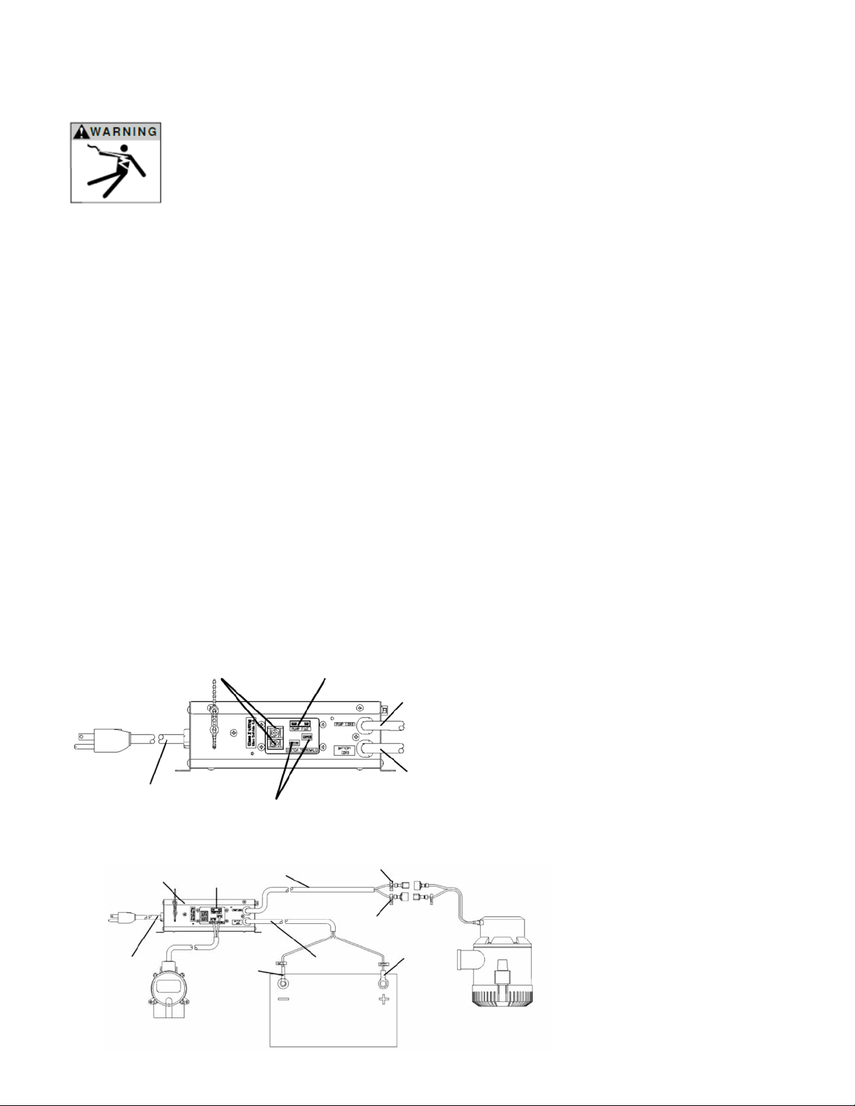
Step 2 – Electrical Connections
Charger/Controller Unit Electrical Connections
Normally Open Circuit
Terminals for Class 2
Alarm or Dialer
Pump Fuse 32 V, 20 Amp
Type ATC
Pump Cord
Battery Cord
Backup Pump Switch Terminals
Charger Controller
Power Supply Cord
Pump Cord
Pump
Fuse
Charger
Controller Unit
Charger
Controller
Power Supply
Cord
Pump Negative Lead
Battery
Positive
Lead
Battery
Negative
Lead
Pump
Positive
Lead
12 VDC Deep
Cycle Battery
Backup Pump
Control Switch
12 VDC
Backup
Pump
Wiring Diagram
Figure 8
Figure 9
17
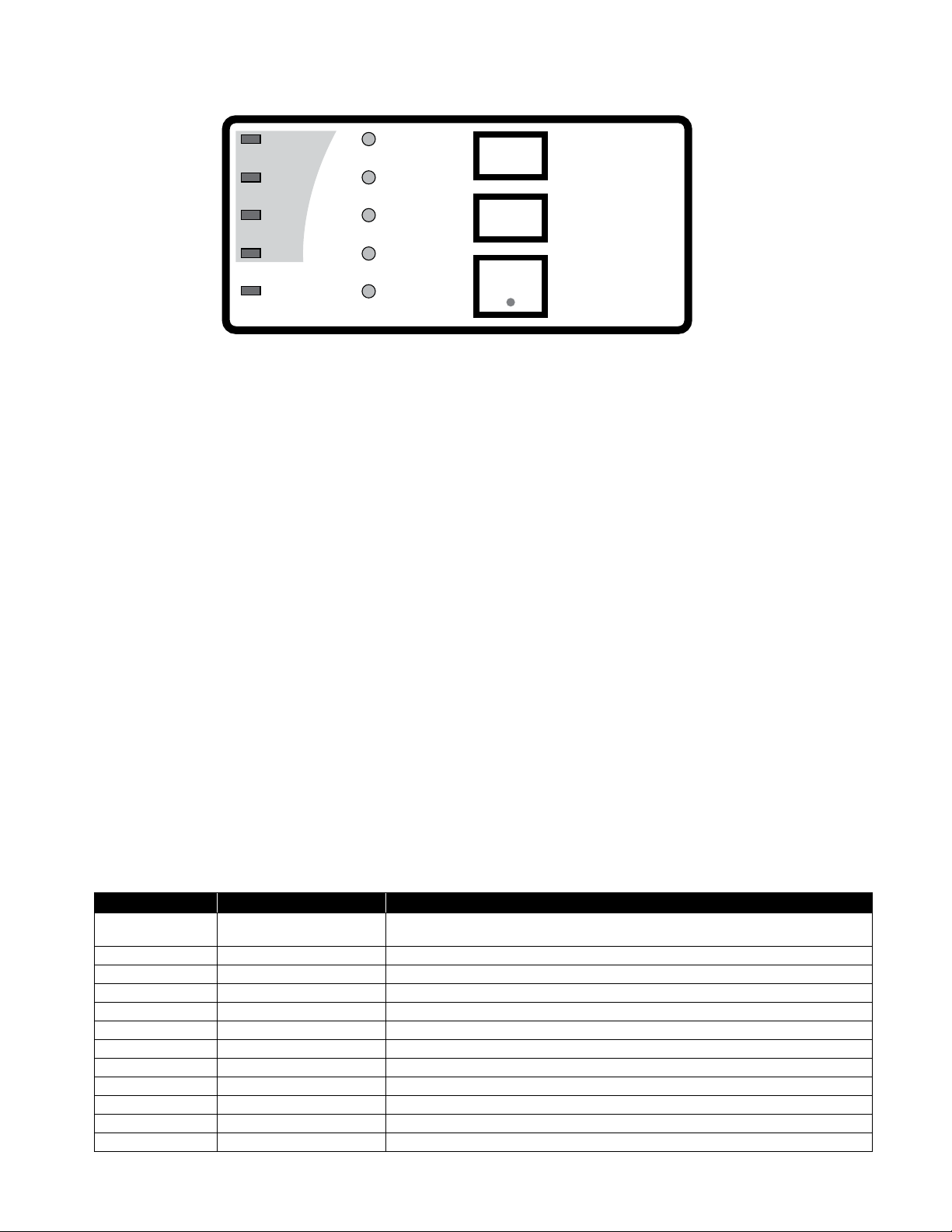
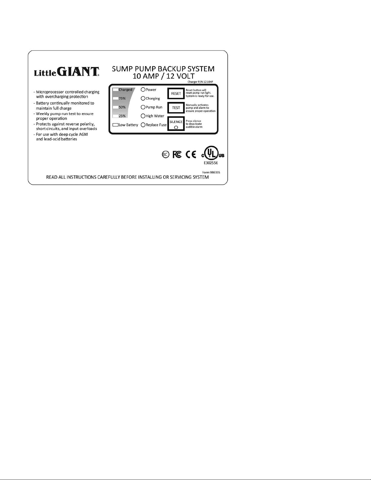
Charger/Controller Unit Operation
1. The upper left side of the face plate provides an approximation of the battery charge. In normal operation the charge will
typically show 25%, 50%, and 75% lights lit. When these are lit the system is indicating the approximate power available
to the pump. A maintenance charge to the battery is happening between “75% and Charged” which means the charger is
maintaining the maximum capacity the battery is capable of producing when “75% and Charged” indicators are lit.
2. The green “Charging” indicator is lit when the battery is charging. When the “Low Battery” indicator is lit the 12 VDC backup
pump will not function properly. A new fully charged 90AH deep cycle battery will allow the 12 VDC backup pump to operate
for about 1 day assuming that the pump has a cycle of 1 minute on and 4 minutes o. The time you have will depend upon
the age of the battery, the charge in the battery, and how often the 12 VDC pump must run. An older battery will provide less
time. The 115 VAC primary pump must be made operational in the time you have before the “Low Battery” light comes on.
For the battery to begin recharging, 12 VDC pump must not be drawing power from the battery. A fully discharged 90AH
battery requires approximately 9 hours to fully charge. Batteries must be re-charged soon after being discharged or possible
damage to the battery will occur.
3. The red “Power” indicator will come on when the 115 VAC plug is plugged into power and power is available. If no power is
available then the light does not light and the charger will not charge the battery.
4. The “Pump Run” indicator comes on when the switch that controls the battery backup pump rst activates. The indicator will
remain on until “RESET” button is pushed.
5. The “High Water” indicator comes on when the pump is actively trying to remove water from the sump. The switch for the 12
VDC pump is in the on position and providing power to the 12 VDC pump when lit. When switch is in o position the indicator
is o and no power is going to the pump.
6. The “Fuse” indicator is lit when the Fuse has failed. Replace with automotive type 32 V, 20A type ATC fuse, on the bottom of
the charger.
7. The “RESET” switch will reset the system if the switch is no longer activated. System will then check to verify everything
is normal and if so, system re-sets. If any problems such as switch still activated, this indicator will again be lit, the audible
alarm will sound and the battery status will be veried.
8. The “Test” button allows you to manually verify that pump operates without having to activate the switch. Press and hold the
button and you should hear the pump operating.
9. The “Silence” button turns o the audible alarm.
Charged
75%
50%
25%
Low Battery
Power
Charging
Pump Run
High Water
Replace Fuse
RESET
TEST
SILENCE
Reset button will
reset pump run light.
System is ready for use.
Manually activates
pump to ensure
proper operation
Press silence
to deactivate
audible alarm
18
Figure 10
ITEM FUNCTION DESCRIPTION / OPERATIONS
Charged – 75% LED Indicators
Indicates battery is between 75% and Fully Charged. Charger is in maintenance
mode to maintain highest battery capacity possible.
50% LED Indicator Indicates the battery level based on a voltage level
25% LED Indicator Indicates the battery level based on a voltage level
Low Battery LED Indicator Indicates battery is critically discharged, pump will not work
Power LED Indicator Indicates AC power is present
Charging LED Indicator Indicates battery is receiving current from the charger
Pump Run LED Indicator Indicates the pump ran and system has not been re-set
High Water LED Indicator Indicates the switch contact is closed
Replace Fuse LED Indicator Indicates the pump circuit has no power & 20A fuse must be replaced
RESET Button/Key This switch will reset system
TEST Button/Key Depress & hold this switch allows you manually test 12 VDC pump.
SILENCE Button/Key This switch turns o the buzzer and a yellow silence indicator comes on

19
Sump System Operation Testing
s WARNING
!
WARNING
Always disconnect the electrical power before touching the pump or discharge when water is
present in the area of the pump. Failure to do so can result in hazardous electrical shock.
s WARNING
!
CAUTION
Ensure all hose clamp connections and threaded connections are tight and that all plumbing slip t
connections are properly glued prior to starting the sump pump system. Failure to do so can result in damage to pump system
and/or cause property damage due to ooding.
s WARNING
!
CAUTION
Do not allow the pump to run dry or damage to the pump will occur. Do not allow the sump basin to
overow during this testing.
Step 1
a. Verify that all wiring is per instructions and that primary pump and controller are connected to power.
i. The red “Power” indicator light should be lit on the Charger/Controller Unit.
Step 2
a. Run water into the sump basin until the primary pump is activated.
i. Do not attempt to run the pump without water; this could result in permanent damage to the pump.
ii. Conrm that primary pump and its control switch are functioning as intended.
iii. Conrm that ON-OFF levels are within specication and conrm that no potential obstructions exist that could inhibit
switch operation.
iv. Conrm that there are no leaks in the primary pump discharge plumbing and main home drain pipe plumbing.
a) It is normal for a stream of water to spray from the air bleed hole in the primary pump’s plumbing. Conrm that this
spray is captured within the sump basin.
Step 3
a. After primary pump function has been conrmed, disconnect power to primary pump.
i. This is typically done at an electrical connection box or a plug receptacle.
Step 4
a. Run water into the sump basin until the backup pump is activated.
i. Do not attempt to run the pump without water; this could result in permanent damage to the pump.
ii. Conrm that backup pump and its control switch are functioning as intended.
iii. Conrm that the Charger/Controller Unit emits an audible alarm when running the backup pump.
a) Press SILENCE button on the Charger/Controller Unit to silence the audible alarm.
iv. Conrm that ON-OFF levels are within specication and conrm that no potential obstructions exist that could inhibit
switch operation.
a) The RS-12 switch will activate the 12 VDC backup pump when water is approximately 6 inches above the
bottom of the RS-12 switch.
v. Conrm that there are no leaks in the backup pump discharge plumbing and main home drain pipe plumbing.
a) It is normal for a stream of water to spray from the air bleed hole in the backup pump’s plumbing. Conrm
that this spray is captured within the sump basin.
Step 5
a. After backup pump function has been conrmed, disconnect power to the Charger/Controller Unit to conrm proper
battery function.
i. This is typically done at an electrical connection box or a plug receptacle.
Step 6
a. Run water into the sump basin until the backup pump is activated.
i. Conrm that backup pump and its control switch are functioning as intended.
ii. Conrm that the Charger/Controller Unit emits an audible alarm when running the backup pump.
a) Press SILENCE button on the Charger/Controller Unit to silence the audible alarm.
Step 7
a. After primary pump, backup pump and Charger/Controller Unit function has been conrmed, reconnect power to the
Charger/Controller Unit and the primary pump
i. Conrm that primary pump activates and evacuate the remaining water from the sump basin down to the normal OFF
level of the primary pump. Primary pump should deactivate when the OFF level is reached.
Step 8
a. Charger/Controller Unit faceplate indicators should provide status of battery’s charge.
i. See Charger/Controller Unit Operation section for details.
Step 9
a. Conrm that battery is in working condition according to the battery manufacturer’s instructions and is fully charged.
Step 10
a. The primary and backup pumps are now ready for operation.

20
s WARNING
!
CAUTION
The backup pump and the primary pump are designed for pumping clear water only. Do not use the
pumps in applications where euent (grey water), sewage or any other debris (gravel, sand, oating debris, etc.) is present.
s WARNING
!
CAUTION
Do not allow the sump basin to overow during this maintenance.
s
!
NOTICE: Inspect and test the sump system condition and operation every 3 months (more frequently in heavy
use applications).
Step 1
a. Refer to battery manufacturer’s instructions to conrm that battery is in working condition and is fully charged.
i. Clean any corrosion from the battery posts or pump terminals.
Step 2
a. Remove all debris (gravel, sand, oating debris, etc.) from the sump basin.
b. Review sump system components for any build-up (minerals, etc.) that would inhibit functionality of the components.
i. If signicant, remove build-up or replace aected components.
Step 3
a. Conrm that all exible coupling hose clamps are fully engaged with plumbing and fully tightened.
Step 4
a. Test operation of the sump system following the instructions outlined in the Sump System Operation Testing section of
this manual.
s WARNING
!
WARNING
Disconnect power from all electrical equipment housed within the sump
system before working on or around the sump pump or battery backup system beginning with
115 VAC powered pumps, level switches, and charger controllers; followed by DC powered
items. Includes all items such as pumps, level control switches, Charger/Controller Unit, and
battery systems.
System Maintenance:

Troubleshooting
21
TROUBLESHOOTING INFORMATION
PROBLEM PROBABLE CAUSES 115 V 12 V CORRECTIVE ACTION
Pump does not turn on or turn o.
Bad connection X X Plug-in pump
Blown fuse X Turn on circuit breaker or replace fuse
Bad battery X Replace battery
Pump impeller obstructed X X Pull pump and clean
Pump control switch X X Replace switch
Pump does not deliver
rated capacity.
Low battery X
When power is restored, the charger will
charge the battery
Check valve installed backwards X X
Check ow indication arrow on check valve
body to ensure it is installed properly
Low voltage, speed too slow X X
Check for proper supply voltage to make
certain it corresponds to name plate voltage.
Impeller or discharge pipe is clogged X X
Pull pump and clean. Check pipe for scale or
corrosion
Pump cycles continually.
Defective battery X Replace battery
No check valve in long discharge pipe
allowing liquid to drain back into sump.
X X Install a check valve in discharge line
Check valve leaking X X Inspect check valve for correct operation
Sump pit too small for inow X X Install larger sump pit
Pump will not shut o.
NOTE: Before troubleshooting
automatic control, check to see that
pump operates on manual control.
To do this, create slight vacuum on
breather tube (near plug), then close
o tube with thumb, plug into wall
outlet. If pump works, proceed to
check switch; if not, fault is in pump
or power supply.
Pump control switch X X Replace switch
Plugged vent tube X Clear vent tube of any obstruction
Dirt or sediment lodged between
retainer ring and rubber diaphragm
causing contacts to remain closed
X Clean area around rubber diaphragm
Pump is air locked X X
Shut power o for approximately 1 minute,
then restart. Repeat several times to clear
air from pump. If system includes a check
valve, a 3/16" hole should be drilled in the
discharge pipe between the pump discharge
and the check valve.
Liquid inow matches pump capacity X X Larger pump required
Pump runs but does not
discharge liquid.
Check valve installed backwards X X
Check ow indicating arrow on check valve
body to ensure it is installed properly.
Check valve stuck or plugged X X
Remove check valve and inspect for proper
operation
Lift too high for pump X X
Check pump performance as compared to
the vertical distance needed to evacuate the
sump water
Inlet to impeller plugged X X Pull pump and clean
Pump is air locked X X
Shut power o for approximately 1 minute,
then restart. Repeat several times to clear
air from pump. If system includes a check
valve, a 3/16" hole should be drilled in the
discharge pipe between the pump discharge
and the check valve.

LIMITED WARRANTY
THIS WARRANTY SETS FORTH THE COMPANY’S SOLE OBLIGATION AND PURCHASER’S EXCLUSIVE REMEDY
FOR DEFECTIVE PRODUCT.
Franklin Electric Company, Inc. and its subsidiaries (hereafter “the Company”) warrants that the products accompanied by this warranty are
free from defects in materials or workmanship of the Company that exist at the time of sale by the Company and which occur or exist within
the applicable warranty period. Any distributor, sub-distributor, recipient, end-user and/or consumer agrees that by accepting the receipt of
the products, the distributor, sub-distributor, recipient, end user and/or consumer expressly agree to be bound by the terms of the warranty
set forth herein.
I. Applicable Warranty Period
The products accompanied by this warranty shall be covered by this Limited Warranty for a period of 24 months from the date of original
purchase by the consumer. In the absence of suitable proof of purchase date, the warranty period of this product will begin to run on the
product's date of manufacture.
II. Instructions Applicable to this Limited Warranty
1. Consumers wishing to submit a warranty claim must return the products accompanied by this warranty to the point of purchase for
warranty consideration.
2. Upon discovery of a defect, any personal injury, property damage or any other type of resulting damage, if applicable, shall be
reasonably mitigated to the extent possible.
3. At its discretion, the Company may inspect products either at its facilities or in the field, and after determination of a warranty claim,
will, at its option, repair or replace defective parts. Repaired or replaced parts will be returned freight prepaid by the Company.
4. This warranty policy does not cover any labor or shipping charges. The Company shall not be liable for any costs or charges
attributable to any product testing, maintenance, installation, repair or removal, or for any tools, supplies, or equipment needed to
install, repair, or remove any product.
III. Limitations Applicable to this Limited Warranty
THIS WARRANTY DOES NOT APPLY TO ANY OF THE FOLLOWING:
1. Any product that is not installed, applied, maintained, and used in accordance with the Company's published instructions,
applicable codes, applicable ordinances and/or with generally accepted industry standards.
2. Any product that has been subject to misuse, misapplication, neglect, alteration, accident, abuse, tampering, acts of God (including
lightning), acts of terrorism, acts of war, fire, improper storage or installation, improper use, improper maintenance or repair,
damage or casualty, or to an excess of the recommended maximums as set forth in the product instructions.
3. Any product that is operated with any accessory, equipment, component, or part not specifically approved by the Company.
4. Use of replacement parts not sold by the Company, the unauthorized addition of non-Company products to other Company
products, and the unauthorized alteration of Company products.
5. Products damaged by normal wear and tear, normal maintenance services and the parts used in connection with such service, or
any other conditions beyond the control of the Company.
6. Any product that has been used for purposes other than those for which it was designed and manufactured.
7. Any use of the product where installation instructions and/or instructions for use were not followed.
The Company reserves the right at any time, and from time to time, to make changes in the design and/or improvements upon its product
without thereby imposing any obligation upon itself to make corresponding changes or improvements in or upon its products already
manufactured and/or previously sold. The Company further reserves the right to substitute parts or components of substantially equal quality
in any warranty service required by operation of this Limited Warranty.
This written Limited Warranty is the entire warranty authorized and offered by the Company. There are no warranties or representations
beyond those expressed in this document.
THIS WARRANTY AND REMEDY IS IN LIEU OF ALL OTHER WARRANTIES AND REMEDIES INCLUDING, WITHOUT LIMITATION,
22

WARRANTIES OF MERCHANTABILITY AND/OR FITNESS FOR A PARTICULAR PURPOSE, WHICH ARE HEREBY SPECIFICALLY
DISCLAIMED AND EXPRESSLY EXCLUDED. CORRECTION OF NON-CONFORMITIES, IN THE MANNER AND FOR THE PERIOD OF TIME AS
SET FORTH ABOVE, SHALL CONSTITUTE FULFILLMENT OF ALL LIABILITY OF THE COMPANY TO THE PURCHASER WHETHER BASED
ON CONTRACT, NEGLIGENCE, OR OTHERWISE.
THE COMPANY SHALL NOT BE LIABLE FOR INCIDENTAL, CONSEQUENTIAL OR SPECIAL DAMAGES SUCH AS, BUT NOT
LIMITED TO:
DAMAGE TO OR LOSS OF OTHER PROPERTY OR EQUIPMENT, LOSS OF USE OF EQUIPMENT, FACILITIES OR SERVICE, LOSS OF
PROFIT OR SALES, COST OF PURCHASES OR REPLACEMENT GOODS, CLAIMS OF CUSTOMERS OF THE PURCHASER, FAILURE
TO WARN AND/OR INSTRUCT, LOSS OF OTHER PRODUCTS, OR COSTS OF ENVIRONMENTAL REMEDIATION, OR DIMINUTION
IN PROPERTY VALUE. THE REMEDIES OF THE PURCHASER SET FORTH HEREIN ARE EXCLUSIVE, AND THE LIABILITY OF THE
COMPANY SHALL NOT, EXCEPT AS EXPRESSLY PROVIDED HEREIN, EXCEED THE PRICE OF THE PRODUCTS UPON WHICH
SUCH LIABILITY IS BASED. DAMAGES AS SET FORTH IN THIS PARAGRAPH SHALL BE REASONABLY MITIGATED TO THE EXTENT
POSSIBLE. THIS PARAGRAPH SHALL ALSO APPLY TO ALL DAMAGES RESULTING FROM CONDITIONS SET FORTH IN SECTION III
ABOVE AND (1) DEFECTS IN PRODUCT PROTOTYPES OR REPLACEMENT PART PROTOTYPES THAT HAVE NOT BEEN PUT INTO
PRODUCTION, CIRCULATED AND SOLD BY THE COMPANY, AND/OR (2) DEFECTS THAT WERE NOT FOUND AT THE TIME OF SALE
DUE TO SCIENTIFIC AND TECHNOLOGICAL REASONS.
This Limited Warranty gives you specific legal rights. You may have other rights, which vary according to the applicable laws and regulations.
Where any term of this warranty is prohibited by such laws, it shall be null and void, but the remainder of this warranty shall remain in full force
and effect.
DISCLAIMER: Any oral statements about the product made by the seller, the Company, the representatives or any other parties, do
not constitute warranties, shall not be relied upon by the user, and are not part of the contract for sale. Seller’s and the Company’s only
obligation, and buyer’s only remedy, shall be the replacement and/or repair by the Company of the product as described above. Before
using, the user shall determine the suitability of the product for his intended use, and user assumes all risk and liability whatsoever in
connection therewith.
23

Form 998912
Rev. 0
08.15
For technical assistance, please contact ................ 800.701.7894
www.littlegiant.com
Franklin Electric Co., Inc.
Oklahoma City, OK 73157-2010
Phone: 1.800.701.7894
Fax: 1.405.228.1561