Loading ...
Loading ...
Loading ...
87
Placement of the Mounting Plate
Placement of the Mounting Plate
INSTALLATION
INSTALLATION
PLACEMENT OF THE MOUNTING PLATE
1
Find the studs, using one of the following
methods:
A. Stud finder–amagnetic device which
locates nails.
B. Useahammer to tap lightly across the
mounting surface to findasolid sound.
This will indicateastud location.
After locating the stud(s), find the center by
probing the wall withasmall nail to find the edges
of the stud. Then placeamark halfway between
the edges. The center of any adjacent studs should
be 16” or 24” from this mark.
Drawaline down the center of the studs.
T
HE MI CROWAVE MU ST BE CONNE CT E D TO
AT L E AST ONE WAL L STUD.
1
Fold back all4carton flaps fully against carton
sides. Then carefully roll the oven and carton over
onto the top side. The oven should be resting in
the Styrofoam.
REMOVING THE MICROWAVE
OVEN FROM THE CARTON/
REMOVING THE MOUNTING
PLATE
FINDING THE WALL STUDS
B
.
A
.
2
Wall
Studs
Center
3
Pull the carton up and off the oven.
2
3
5
4
Cut the middle of the outer protective plastic bag to
remove the mounting plate.
Remove the screws from each end of the mounting
p late. This plate will be used as the rear wall template
and for mounting. Reinstall the screws into the holes
where they were removed.
1
Exhaust Adapter
Filters and Turntable Ring below glass tray
Small Hardware Bag
Shelf (For
some models)
Remove the top cover board, installation
instructions, use and care, exhaust adapter,
turntable ring, shelf, filters, glass tray and the
Styrofoam protecting the front of the oven.
small hardware bag.
Top Cover Board
EPE Pad
Carton
Styrofoam
Screws
Screws
Mounting Plate
DETERMINING WALL PLATE LOCATION UNDER YOUR CABINET
C.
Plate position: beneath flat bottom cabinet
to Cooktop
C
3/
8"
T
O
E
DGE
NOTE: I
T IS VER
Y IMPORTANT T O
READ
A
ND F
O
LLOW TH
E
DIRECTIO
N
S
IN THE IN
S
T
A
L
L
ATION INSTRUCT
IO
N
S
BE
F
O
R
E
PROCEE
DING WITH
T
H
IS
REAR W
A
LL
TEMP
L
A
TE.
This
Rear Wall Te
m
pl
at
e
ser
v
e
s
to position
the botto
m
mountin
g
plate and
to lo
ca
t
e
t
he
ho
rizontal e
xh
aust
out
let.
1.
Use
a
level
t
o check
th
a
t the template
is p
o
s
itioned
a
ccurat
e
ly.
2. Locate and
m
ar
k
at
leas
t
one s
tud
o
n t
h
e
le
f
t
o
r
right
s
ide of t
h
e centerline.
It
is imp
ort
a
nt
t
o use at
le
a
st o
ne wood
screw m
ount
ed
f
ir
mly in a stud to s
u
ppor
t
the weight
of th
e
microwave. M
ark two
ad
d
itional,
ev
e
nly
s
paced
loca
t
ions for
the su
pplied toggle
bolt
s
.
3. D
r
ill holes
in the
m
arked
locat
ions.
Where there
is
a
stud, dr
ill a 3
/1
6
" hole f
o
r
wood screws
.
F
o
r holes
that
d
o not
li
ne up wit
h
a
s
t
ud
,
drill 5/8"
holes
for
togg
le
bolts.
D
O
NOT INSTALL
T
H
E
M
O
UNT
ING P
L
ATE
AT
TH
IS
TIM
E.
4.
Rem
ove the te
m
plate
f
rom t
h
e r
e
ar wall.
5.
R
e
view t
h
e Installation
I
nstruction book f
o
r your
installat
ion si
tuation.
L
o
c
a
t
e and m
a
rk h
o
l
es
to ali
g
n wit
h
ho
l
es in
the
mo
u
n
t
in
g p
l
a
te.
IMPORTA
NT
:
LO
C
ATE AT LEAS
T
ONE S
T
U
D ON EITH
ER
SIDE
O
F
T
HE CEN
TERLINE.
MARK
T
H
E
LOCAT
ION
F
OR
2 AD
D
IT
I
ONAL,
E
V
ENLY
SPAC
E
D TO
GGLE
B
OL
T
S
IN
THE
MO
UN
TING P
L
AT
E
A
RE
A
.
Locate a
nd
ma
r
k
hol
e
s to
a
l
ign with ho
l
es i
n
t
h
e
mountin
g
pl
a
te.
IMPO
RTA
N
T
:
LOCA
TE
A
T
L
EA
ST
ON
E
ST
U
D ON EITH
E
R SIDE OF
T
H
E
C
E
N
T
E
RLIN
E
.
MARK THE
L
OCA
T
I
ON
F
OR 2
AD
D
IT
IONAL
, EVENLY
S
P
A
CE
D TOGGLE BOLT
S
IN
T
H
E
MOUN
TING
P
LATE
AR
E
A.
T
rim th
e rea
r
wall te
m
p
l
a
te
alo
ng t
he d
otted line.
Trim
the r
ear
wa
ll
te
m
p
l
a
te
alo
n
g th
e
d
o
tted l
in
e.
12"
4"
D
arle
vu
e
lt
a a
la h
o
ja
para
c
on
s
u
lt
ar la
ve
r
sión
en E
spañol.
3/8
"
TO EDGE
N
O
TE:
I
T IS
VER
Y
IMPOR
TAN
T T
O
READ
AND FOLLO W TH E D IR
EC
TION
S
I
N
TH
E
INSTALL
ATION
INST
RUCTIO
NS
BEFO
R
E
PR
O
C
EEDING
W
ITH TH
I
S
R
EAR W
AL
L
T
EMPL
AT
E.
This Re ar Wall Te mp
late serves to
posit
i
o
n
the
bot
to
m
mou
ntin
g plate and to loc ate th e h oriz ontal e
x
ha
ust
outlet.
1. Use a
l
ev
el to check
th
a
t the templat e is
p
ositioned
accurately.
2. Loca
te
and
ma
rk
a
t least one s tu d on t he left o
r
r
ight side o
f
the centerlin e.
It is importan t to u s
e a
t least o
ne
wo
od
s
c
r
e
w mounted firmly in a s tu d to s u pport
the weigh
t
of the
mic
rowave. Mar
k two additio
nal, evenly s paced
locatio
ns for the s upp lied t oggle b o
lts.
3. Drill holes in the ma rke d
loc
ations
. Whe
re there is
a stud, drill
a 3/16" hole for w
ood sc
rews
. For ho
les
that do n
o
t line up
with a s
tud,
drill 5
/8" holes for
to
g
gle bolts.
DO NOT INSTAL L TH E MO
U
N
TING PLATE
AT THIS
TI
ME.
4. Re
m
ove
th
e te
mpla
te from the r ear w a
ll.
5. Revie
w
the Ins
ta
llation
In
struction book fo r your
installation situ atio n.
Locate an
d
ma
rk
holes to alig n wit h h oles
i
n the
mounti
ng plat
e
.
IMPORT
ANT:
LOC
ATE AT LEAST
ONE STUD
ON
EITHER SI
D
E OF
TH
E CENTER LINE.
MAR
K T
H
E
LOC
ATIO
N FOR 2
ADDITIONAL
,
EVEN
L
Y
SPAC
ED
TOGGLE BO
LTS I
N
THE MOUNT
I
NG
PLATE
AREA
.
Locate
and
ma
rk
h
ol
es t
o al
i
gn w
it
h
h
ol
es
in t
h
e
mo
untin
g pl
a
t
e.
IMPO
R
TANT:
LOC
AT
E AT
LEAS
T ON
E ST
U
D
ON EI
T
HER SID E OF
TH
E
CENTE R LIN
E
.
MARK T
HE LOCATIO N
F
O
R 2 AD
D
ITIONAL, EVEN LY
SPA
CE
D
T
O
G
GLE
BOL
T
S I
N
TH
E
MOUNTI
NG P
LATE
AR
EA.
Trim th e
rear
wall
templat
e
a
l
ong th e dotted
line.
Trim
the
r
ear wall
tem
plate al
ong
the
dotted li
ne.
12"
4"
D
arle
vuelt
a
a
la
h
oja par
a
consu lta
r
la
versión en E s pañ ol.
A
t
l
e
a
s
t
3
0
ʺ
C
3/8" TO EDGE
N
O
T
E
:
I
T IS
V
ER
Y IMPORT ANT
TO
READ A
N
D FOLLO W
THE
DIREC
TIONS
I
N T
HE
I
N
S
TAL
L
ATION I
N
STRU
C
TION
S
B
E
F
ORE P R OC
EE
D
ING WI
TH
TH
I
S
R
E
AR WALL T EM P
LAT
E
.
This
Rear Wa
l
l Template se rv
es to
p
os
i
tio
n the bo
t
to
m
mounting
pla
te and t
o
locate
the
ho
r
izontal
exhaust
o
utle
t
.
1. Use a level to ch
e
c
k
t
hat th
e
template is pos i
tioned
a
ccu
rately.
2
.
L
ocate and mark a
t
le
ast one stu d
on the left
o
r
right
sid
e of t
he
c
enterlin
e.
It is impor
ta
nt to use at leas t o ne wo o
d
scre
w
mo
unted firmly in a
s
t
ud to support the weigh t
of
t
he microwa
ve
.
Mark two
a
dditi
o
nal
, evenly
sp
aced
locations for th
e supplied
togg
le bo
l
t
s.
3. Drill holes in th
e
m
arke
d loca
t
ion
s.
Where there is
a stud, dril l a
3/16" h
o
le
for woo
d s
cre
w
s.
For holes
that do not lin
e
u
p
with
a
stud
, drill 5/8
"
holes for
togg
le
bo
lts
.
DO
NOT INSTAL L
T
HE
MOUNT
ING PLA
TE
AT TH
IS
T
IME.
4
. Remove t he tem p
late
from
the rear
wal
l.
5. Revi
ew the Ins
ta
l
lation In
stru
ction book for
your
installation
situation
.
Lo
cate and mar k
holes
t
o
al
ign w
ith holes
in t
h
e
m
o
unt
ing plate.
I
MP
ORT
A
N
T:
LO
C
ATE AT
LE
A
ST ON
E
S
TUD ON E
ITH
ER
S
I
DE
OF
TH
E C
EN
TERLI NE .
M
ARK TH
E
LOCATION
F
OR 2 A
D
D
I
TION
AL, EV ENL
Y
S
P
A
CED
TOGGL
E
BOLT
S IN THE
M
OUNTING P
LAT
E
A
REA.
Loc
at
e
a
nd
mar
k holes
t
o
align
w
ith holes
in
t
he
m
o
u
nt
i
ng plat
e
.
I
MPORTAN
T:
LOCATE AT LEA ST
ON
E
S
TUD
ON E
ITH
ER SI DE OF
TH
E CENT ER LI NE
.
MARK
T
H
E LOC
ATION F
OR
2
A
DD
I
TI
ON
AL,
EVE
NLY
SPA
C
ED
TOGGLE BOL T S
IN THE MOUNT ING
PLATE
ARE
A.
Trim
the re
a
r wall te m
pl
ate along
the
d
ot
ted
li
n
e.
Trim t h
e
rear
wa
ll
tem
p
l
a
t
e
a
l
ong
th
e
d
o
t
t
e
d
li
ne.
12"
4"
Da
rle
vuelta a la ho ja pa ra
c
on
s
ultar la
versión
en Espa
ñol.
Your cabinets may have decorative trim that
interferes with the microwave installation. Remove
the decorative trim to install the microwave properly
and to make it level.
THE MICROWAVE MUST BE LEVEL.
Measure the inside depth of the front overhang.
Draw a vertical line on the
wall at the center of the
30
ʺ wide space. Tape the
Rear Wall Template onto
the wall matching the
centerline and touching
the bottom of the cabinet.
Draw a vertical line on the wall at the center of the
30
ʺ space.
Tape the Rear Wall Template onto the wall matching the
centerline and touching the bottom cabinet frame.
C
3/
8"
TO ED
G
E
NOTE:
I
T
IS
VERY
IMPORT AN
T
TO
RE
A
D
A
ND F
OLLOW THE DIRE CTIONS
IN THE INS TALLA
TION I
NS
T
RUCT
I
ONS
BEFOR
E
PROCE E
D
ING
W
I
T
H
THIS
REAR W
A
LL
T
EMPL
ATE
.
This R
ear
Wa
ll Template se r ves to
position the b ott
om
mounting
p
late
and to locate t he
horiz
on
tal exhaust
outl
e
t
.
1
.
Use a l
e
ve
l
to
ch
eck that the
te
mplate is posi tion ed
accur
ately.
2
.
Locate a
nd
ma
r
k at le
ast o
n
e stud on th e le
ft or
r
i
ght side o
f
the
centerl
i
ne.
It
is importan
t to use
a
t
l
east one
wo
od
screw mo
u
nte
d
firmly in
a
stud
t
o su
ppo
rt
the we
ight
of the micro
w
ave. Mark
t
wo
ad
ditional
,
evenly spa
ce
d
l
o
cations for th e su ppli ed tog gle b
olts.
3. Drill holes
in
t
h
e m
ar
ked lo
cat
io
n
s. Where the re
is
a stud,
d
rill a
3/16"
h
ole
for woo
d
screws. F or ho l
es
t
h
at
d
o
not line up w
it
h
a stu
d, drill 5/8
"
h
oles fo
r
t
o
gg
le
b
o
lt
s
.
DO
NO
T IN
STALL
THE MOU
NTING PLAT E
AT TH
IS TIME.
4.
R
e
move th
e
t
emplate fr
o
m the rear wa ll.
5.
R
eview the Insta lla
tio
n I
n
struction book f or yo
ur
i
n
stallat
i
o
n situation.
Locat
e and
mark
hol
es
t
o align with
h
oles
i
n
the
mo
unti
ng
p
l
ate.
I
MPO
RTA
N
T:
LOCA
TE
A
T
LEAS
T
ONE
STUD
ON E
IT
HER S
IDE
O
F
THE
C
E
N
T
ER
LINE.
MA
RK T
HE
LOCATI
O
N
FOR 2 AD
DITIO
NAL, EVE NL Y
SP
A
CED TOGG LE
B
OLTS IN TH
E
MOUNTI
NG PLAT E
A
R
EA
.
Loc
a
t
e and mark ho
les
t
o align
w
i
th
hol
e
s i
n the
mo
unti
ng p
l
at
e.
IMPORT
ANT
:
LOCAT
E AT
LEAST ONE S T UD ON
EITHE
R SI
DE O
F
THE
CENTER L
I
NE.
MARK T
H
E
LOC
AT
ION FOR
2
A
DDIT
I
O
NAL, EVE NL
Y
SPACE
D TO
G
GLE
B
OLTS I
N THE
MOUNTING PL
ATE
A
REA.
Trim t
h
e
rear wa
l
l
temp
late
al
on
g the do tt e
d lin
e.
T
rim th e rea
r wall tem
p
l
a
te
al
o
ng th e do
tted lin
e
.
12"
4
"
Darle vue lt a a
la ho
ja para con s
ult
ar la
ve
rsión e n
E
s
p
año
l.
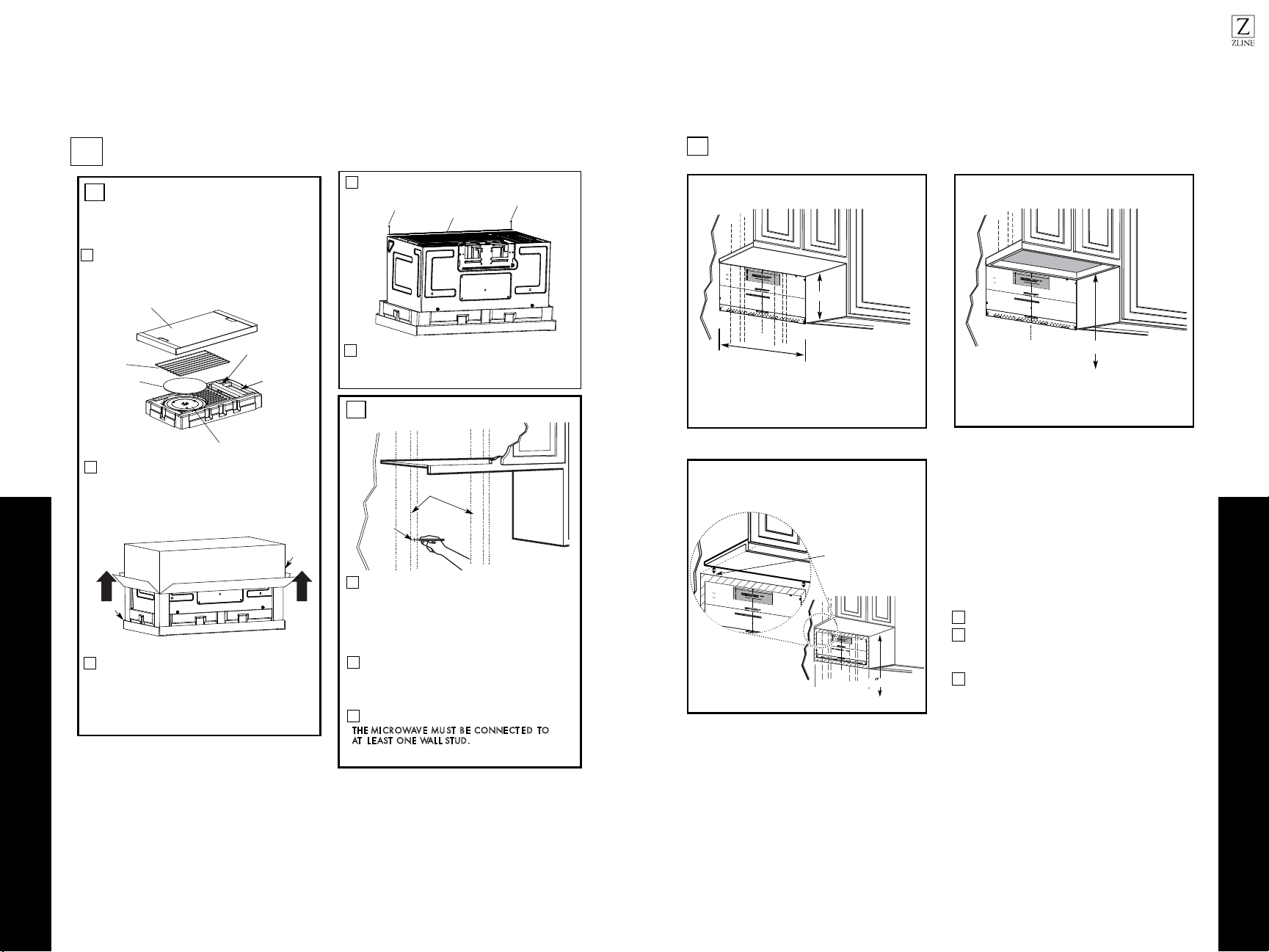
Plate position: beneath framed recessed cabinet
bottom
1
3
2
30” to Cooktop
30
For this type of installation with front overhang only,
align the mounting tabs with this horizontal line, not
touching the cabinet bottom as described in Step D.
16-1/2”
Draw a horizontal line on the back wall, an equal
distance below the cabinet bottom as the inside depth
of the front overhang.
Use a level to make sure the cabinet bottom is level.
If the cabinets have a front overhang only, with no back or
side frame, install the mounting plate down the same distance
as the front overhang depth. This will keep the microwave
level.
Plate position: beneath recessed bottom cabinet
with front overhang
Draw a line on the back
wall equal to the depth of
the front overhang.
Loading ...
Loading ...
Loading ...