Loading ...
Loading ...
Loading ...
1817
Outside Back Exhaust
Outside Back Exhaust
INSTALLATION
INSTALLATION
•
•
Remove and save the screw that holds the blower
plate to the microwave. Lift off the blower plate.
Back of
Microwave
P
P
R
R
E
E
P
P
A
A
R
R
I
I
N
N
G
G
T
T
H
H
E
E
R
R
E
E
A
A
R
R
W
W
A
A
L
L
L
L
F
F
O
O
R
R
O
O
U
U
T
T
S
S
I
I
D
D
E
E
B
B
A
A
C
C
K
K
E
E
X
X
H
H
A
A
U
U
S
S
T
T
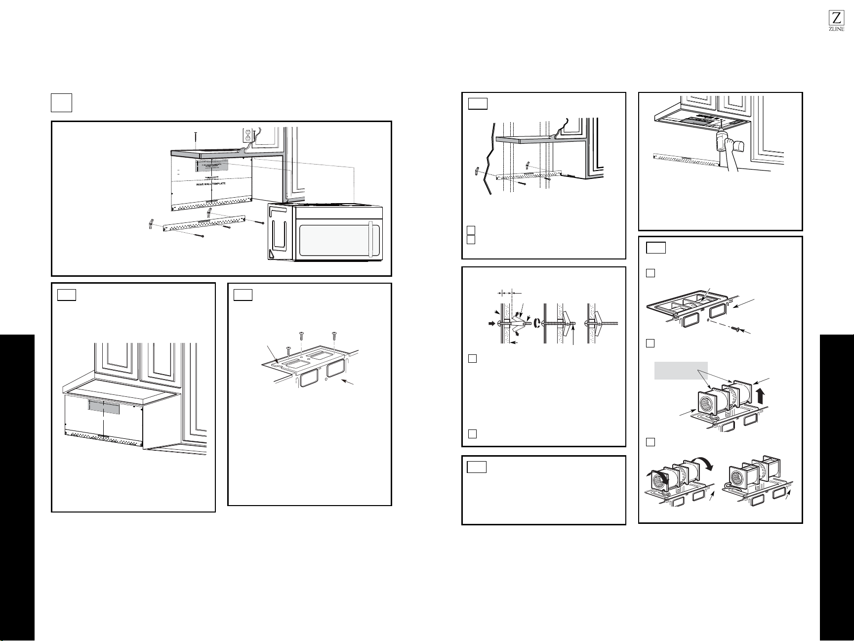
B1.
You need to cut an opening in the rear wall for
outside exhaust.
• Read the instructions on the REAR WALL TEMPLATE.
• Tape it to the rear wall.
• Cut the opening, following the instructions of the
REAR WALL TEMPLATE.
B2.
OUTSIDE BACK EXHAUST (Horizontal Duct)
B
Blower Plate
R
R
E
E
M
M
O
O
V
V
E
E
B
B
L
L
O
O
W
W
E
E
R
R
P
P
L
L
A
A
T
T
E
E
I
I
N
N
S
S
T
T
A
A
L
L
L
L
A
A
T
T
I
I
O
O
N
N
O
O
V
V
E
E
R
R
V
V
I
I
E
E
W
W
B
B
1
1
.
.
Prepare Rear Wall
B
B
2
2
.
.
Remove Blower Plate
B
B
3
3
.
.
Attach Mounting Plate to Wall
B
B
4
4
.
.
Prepare Top Cabinet
B
B
5
5
.
.
Adjust Blower
B
B
6
6
.
.
Mount the Microwave Oven
I
I
M
M
P
P
O
O
R
R
T
T
A
A
N
N
T
T
N
N
O
O
T
T
E
E
S
S
:
:
3/8" TO EDGE
NO
TE: IT IS VE
RY IMPORT
ANT TO
READ AND FOLLOW THE DIRECTIONS
IN THE INSTALLATIO
N
INSTRUCTIONS
BEFO
RE PROCEED
ING WITH
THIS
REAR
WALL TEMPLATE.
This Rear Wall Templat
e serves to position the bottom
mounting plate and to locate the
horizontal exhaust
outlet.
1. Use a level to check t
hat t
he template is positioned
accurately.
2. Locate and mark at least one stud on the left or
right side of the centerline.
It is important to use at least one wood
screw mounted firmly in a stud to support the weight
of the microwave. Mark
two additional,
evenly spaced
locations for the supplied toggle bolts.
3. Drill holes in the marked locations. Where there is
a stud, drill a 3/16" hole f
or wood screws. For holes
that
do not line up wit
h a stud, drill 5/8" holes for
toggle bolts.
DO NOT INSTALL T
HE MOUNTING PLATE
AT THIS TIME.
4. Remove the template from the rear wall.
5. Review th
e Installation Instruction book for your
installation situation.
Locate and mark holes to align with holes in the
mounti
ng p
late
.
IMPORTANT:
LOCATE
AT LEAST ONE STU
D
ON EITH
ER SIDE OF
THE CENTERLINE.
M
A
RK THE LOC
ATION FOR 2 ADDITIONAL, EVENLY
SPACED TOGGLE BOLTS IN THE MOUNTING PLA
TE
AREA.
Locate and mark hol
es to
align with holes
in the
mounting
plate.
IMPORTA
NT:
LO
CATE AT LEAST ONE STUD O
N EIT
HER SIDE OF
THE CENTERLINE.
MA
RK THE L
OCATION FOR 2 ADDITIONAL, EVENLY
SPACED TOGG
LE BO
LTS IN THE MOUNTING PLATE
AREA.
Trim the rear wall template along the dotted line.
Trim the rear wall template alo
ng
the dotted line.
12"
4"
Darle vuelta a la hoja para consultar la
versión en Español.
Make sure the screws for the blower
motor and blower plate are securely
tightened when they are
reinstalled. This will help to
prevent excessive vibration.
Make sure the motor wiring has been
properly routed and secured, and
that the wires are not pinched.
12"
4"
NO
TE
: IT IS VERY IMPORTANT TO
READ AND FOLLO
WT NOI
T
C
ERIDEH S
IN THE INSTALLATION INSTRUCTIONS
BE
FO
RE PR
O
CEEDINGWITH TH
IS
REAR W
ALL TEMPLATE.
This RearWall Template serves to position the bottom
mou
nting plateand to locate th
e horizontal exhaust
outlet.
1. Use a levelto
c
heck th
at the t
emplate is positioned
accurately.
2. Locate andmark at least o utsen d on th ro tfele
right
side of the centerline.
It is important to use at least one wood
screw mounted firmly
in a stud to support the weight
ofthe microwave. Mark two additional, even
ly
spa
ced
locatio
ns for the supplied to
g
gle bolts.
3. Drill h
oles in th
e marked locations.Where there is
a stud, dril
l a 3/16" hole for wood scr
ews. F
or holes
thatdo
not lin ht
iwpu e a stud, drill 5/8" holes for
toggle bolts.
DO NOT INSTALL
T
HE MO
U
NTI
NG P
L
ATE
AT THISTIME.
4. Remove th
e template fromthe rear wall.
5.Reviewthe Installa tsnInoit ruction book for your
installation situation.
Locate and mark holes to align with holes in the
mounting
plate.
IMPORTANT:
LOCATE
AT LEAST ONE STUD ON EI
THERSIDE OF
THE CENT
ERLINE.
MARKT
HE LO
CATIONFOR 2 ADDITIONAL, EVENLY
SP
ACE
D T
OGGLE
BOLTS IN THE MOUNTING PLATE
AREA.
Trim the r
e
ar wall template alongthe dotted line.
Da
rlevuelta a la hoja para consul
tarla
versiónen Español.
Locate and mark
holes to align with holes in the
.etalpgnitnuom
IMPORTANT:
LOCATE AT LEAST O IE NO DUTSEN THER SI
DE OF
THE
CENT
E
R
LINE
.
OL EHTKRAM
CATION
FOR 2 ADDITIONA
L, EVENLY
SPACEDTOGGLE BOLTS IN THE MO
UN
TING PLATE
AREA.
Trim the rear wall template along
the dotted line.
3/8"
TOEDGE
ATTACH THE MOUNTING
PLATE TO THE WALL
B3.
•
Read the instructions on the TOP CABINET
TEMPLATE.
•Tape it underneath the top cabinet.
•Drill the holes, following the instructions on the
TOP CABINET TEMPLATE.
CAUTION: Wear safety goggles when drilling holes in the
cabinet bottom.
Wall
Mounting
Plate
Spacing for Toggles More
Than Wall Thickness
Toggle
Bolt
Toggle Wings
To use toggle bolts:
Bolt End
Attach the plate to the wall using toggle bolts.
At least one wood screw must be used to attach the plate to
a wall stud.
Remove the toggle wings from the bolts.
Insert the bolts into the mounting plate through the holes
designated to go into drywall and reattach the toggle
wings3/4" onto each bolt.
1
2
Place the mounting plate against the wall and insert the
toggle wings into the holes in the wall to mount the plate.
NOTE: Before tightening toggle bolts and wood screw,
make sure the bottom of the mounting plate touch the
bottom of the cabinet when pushed flush against the wall
and that the plate is properly centered under the cabinet.
CAUTION: Be careful to avoid pinching fingers
between the back of the mounting plate and the wall.
Tighten all bolts. Pull the plate away from the wall
to help tighten the bolts.
3
4
2
1
Remove and save screw that holds blower motor
to microwave.
ADAPTING MICROWAVE
BLOWER FOR OUTSIDE
BACK EXHAUST
B5.
End B
End A
will extend far enough to allow you to adjust
the blower unit.
Back of
Microwave
Blower Motor
Blower Motor
Screw
Forward
Openings Facing
Carefully pull out the blower unit. The wires
Before: Fan Blade
USE TOP CABINET TEMPLATE
FOR PREPARATION OF TOP
CABINET
B4.
You need to drill holes for the top support screws and
a hole large enough for the power cord to fit through.
Back of
Microwave
Roll the blower unit 90°
Back of
Microwave
3
Before Rotation After Rotation
Loading ...
Loading ...
Loading ...