CLI Reference Guide
Product Model: DXS-3600 Series
Layer 2/3 Managed 10GbE Switch
Release: 1.10
DXS-3600 Series 10GbE Layer 2/3 Switch CLI Reference Guide
ii
DXS-3600 Series CLI Reference Guide
Software Release F/W: 1.10.023
Copyright Statement
All rights reserved.
Without our written permission this document may not be excerpted, reproduced, transmitted, or otherwise in all or part
by any party by any means.
Preface
Version Description
This manual’s command descriptions are based on the software release 1.10.023. The commands listed here are the
subset of commands that are supported by the DXS-3600 Series switch.
Audience
This reference manual is intended for network administrators and other IT networking professionals responsible for
managing the switch by using the Command Line Interface (CLI). The CLI is the primary management interface to the
DXS-3600 Series switch, which will be generally be referred to simply as the “switch” within this manual. This manual is
written in a way that assumes that you already have the experience and knowledge of Ethernet and modern networking
principles for Local Area Networks.
Document Layout
Other Documentation
The documents below are a further source of information in regards to configuring and troubleshooting the switch . All
the documents are available either from the CD, bundled with this switch, or from the D-Link website. Other documents
related to this switch are:
• DXS-3600 Series Hardware Installation Guide
• DXS-3600 Series Web UI Reference Guide
Conventions
Preface Describes how to use the CLI reference manual.
Table of Contents Lists out the chapters discussed throughout this manual.
Chapters Each chapter contains a specific grouping of CLI commands that are related to the
topic labelled.
Appendices Contains extra information related to this switch.
Convention Description
Boldface Font Commands, command options and keywords are printed in boldface. Keywords, in
the command line, are to be entered exactly as they are displayed.
UPPERCASE ITALICS Font Parameters or values that must be specified are printed in UPPERCASE ITALICS.
Parameters in the command line, are to be replaced with the actual values that are
desired to be used with the command.
[ ] Square brackets enclose an optional value or set of optional arguments.
DXS-3600 Series 10GbE Layer 2/3 Switch CLI Reference Guide
iii
Notes, Notices, and Cautions
Below are examples of the 3 types of indicators used in this manual. When administering your switch using the
information in this document, you should pay special attention to these indicators. Each example below provides an
explanatory remark regarding each type of indicator.
Command Descriptions
The information pertaining to each command in this reference guide is presented using a number of template fields.
The fields are:
• Description - This is a short and concise statement describing the commands functionality.
• Syntax - The precise form to use when entering and issuing the command. The form conventions are described in
the table shown under the section “Conventions” on page iv of this guide.
• Syntax Description - A table where each row describes the optional or required arguments, and their use, that
can be issued with the command.
• Default - If the command sets a configuration value or administrative state of the switch then any default settings
(i.e. without issuing the command) of the configuration is shown here.
• Command Mode - The mode in which the command can be issued. The modes are either User EXEC, Privileged
EXEC, Global Configuration or a specific configuration mode. These modes are described in the section titled
“Command Modes” on page v below.
• Command Usage - If necessary, a detailed description of the command and its various utilization scenarios is
given here.
• Example(s) - Each command is accompanied by a practical example of the command being issued in a suitable
scenario.
Command Modes
There are several command modes available in the command-line interface (CLI). The set of commands available to
the user depends on both the mode the user is currently in and their privilege level. For each case, the user can see all
the commands that are available in a particular command mode by entering a question mark (?) at the system prompt.
The command-line interface has five privilege levels:
• Basic User - Privilege Level 1. This user account level has the lowest priority of the user accounts. The purpose of
this type of user account level is for basic system checking.
• Advanced User - Privilege Level 3. This user account level is allowed to configure the terminal control setting.
This user account can only show limited information that is not related to security.
• Power User - Privilege 8. This user account level can execute fewer commands than operator, including configura-
tion commands other than the operator level and administrator level commands.
{a | b | c} Braces enclose alternative keywords seperated by vertical bars. Generally, one of
the keywords in the seperated list can be chosen.
[a | d | c] Optional values or arguements are enclosed in square barackets and seperated by
vertical bars. Generally, one or more of the vales or arguements in the seperated list
can be chosen.
Blue Courier Font
This convention is used to represent an example of a screen console display
including example entries of CLI command input with the corresponding output. All
examples used in this manual is based on the DXS-3600-32S switch in the DXS-
3600 Series.
NOTE: A note indicates important information that helps you make better use of your device
NOTICE: A notice indicates either potential damage to hardware or loss of data and tells you how to
avoid the problem
CAUTION: A caution indicates a potential for property damage, personal injury, or death.
Convention Description
DXS-3600 Series 10GbE Layer 2/3 Switch CLI Reference Guide
iv
• Operator - Privilege Level 12. This user account level is used to grant system configuration rights for users who
need to change or monitor system configuration, except for security related information such as user accounts and
SNMP account settings, etc.
• Administrator - Privilege Level 15. This administrator user account level can monitor all system information and
change any of the system configuration settings expressed in this configuration guide.
The command-line interface has a number of command modes. There are three basic command modes:
• User EXEC mode
• Privileged EXEC mode
• Global Configuration mode
All other sub-configuration modes can be accessed via global configuration mode.
When a user logs in to the Switch, the privilege level of the user determines the command mode the user will enter
after initially logging in. The user will either log into user EXEC mode or privileged EXEC mode. Users with a basic user
level will log into the Switch in user EXEC mode. Users with advanced user, power user, operator or administrator level
accounts will log into the Switch in privileged EXEC mode. Therefore, user EXEC mode can operate at basic user level
and privileged EXEC mode can operate at advanced user, power user, operator or administrator level. The user can
only enter global configuration mode from privileged EXEC mode. Therefore, global configuration mode can be
accessed by users who have advanced user, power user, operator or administrator level user accounts. As for sub-
configuration modes, a subset of those can only be accessed by users who have the highest secure administrator level
privileges.
The following table briefly lists the available command modes. Only the basic command modes and some of the sub-
configuration modes are enumerated. The basic command modes and basic sub-configuration modes are further
described in the following chapters. Descriptions for the rest of the sub-configuration modes are not provided in this
section. For more information on the additional sub-configuration modes, the user should refer to the chapters relating
to these functions.
The available command modes and privilege levels are described below:
Command Mode /
Privilege Level
Purpose
User EXEC Mode /
Basic User level
This level has the lowest priority of the user accounts. It is provided only to check
basic system settings.
Privileged EXEC Mode /
Advanced User level
This level is allowed to configure the terminal control setting. This user account can
only show limited information that is not related to security.
Privileged EXEC Mode /
Power User level
This level can execute less commands than operator, include the configure
commands other than the operator level and administrator level commands.
Privileged EXEC Mode /
Operator level
For changing both local and global terminal settings, monitoring, and performing
certain system administration tasks. The system administration tasks that can be
performed at this level includes the clearing of system configuration settings, except
for any security related information, such as user accounts, SNMP account settings
etc.
Privileged EXEC Mode /
Administrator level
This level is identical to privileged EXEC mode at power user level, except that a
user at the administrator level can monitor and clear security related settings.
Global Configuration Mode /
Power User level
For applying global settings, including the configuration commands other than the
operator level and administrator level commands.
Global Configuration Mode /
Operator level
For applying global settings, except for security related settings, on the entire Switch.
In addition to applying global settings on the entire Switch, the user can access other
sub-configuration modes from global configuration mode.
Global Configuration Mode /
Administrator level
For applying global settings on the entire Switch. In addition to applying global
settings on the entire Switch, the user can access other sub-configuration modes
from global configuration mode.
Interface Configuration Mode /
Administrator level
For applying interface related settings.
VLAN Interface Configuration
Mode
For applying VLAN interface related settings.
VLAN Configuration Mode For applying settings to a VLAN.

DXS-3600 Series 10GbE Layer 2/3 Switch CLI Reference Guide
v
User EXEC Mode at Basic User Level
This command mode is mainly designed for checking basic system settings. This command mode can be entered by
logging in as a basic user.
Privileged EXEC Mode at Advanced User Level
This command mode is mainly designed for checking basic system settings, allowing users to change the local
terminal session settings and carrying out basic network connectivity verification. One limitation of this command mode
is that it cannot be used to display information related to security. This command mode can be entered by logging in as
an advanced user.
Privileged EXEC Mode at Power User Level
User logged into the switch in privileged EXEC mode at this level can execute fewer commands than operator,
including the configuration commands other than the operator level and administrator level commands. The method to
enter privileged EXEC mode at power user level is to login to the switch with a user account that has a privileged level
of 8.
Privileged EXEC Mode at Operator Level
Users logged into the Switch in privileged EXEC mode at this level can change both local and global terminal settings,
monitor, and perform system administration tasks like clearing configuration settings (except for security related
information such as user accounts, SNMP account settings etc.) The method to enter privileged EXEC mode at
operator level is to login to the Switch with a user account that has a privilege level of 12.
Privileged EXEC Mode at Administrator Level
This command mode has a privilege level of 15. Users logged in with this command mode can monitor all system
information and change any system configuration settings mentioned in this Configuration Guide. The method to enter
privileged EXEC mode at administrator level is to login to the Switch with a user account that has a privilege level of 15.
Global Configuration Mode
The primary purpose of global configuration mode is to apply global settings on the entire Switch. Global configuration
mode can be accessed at advanced user, power user, operator or administrator level user accounts. However, security
related settings are not accessible at advanced user, power user or operator user accounts. In addition to applying
global settings on the entire Switch, the user can also access other sub-configuration modes. In order to access the
global configuration mode, the user must be logged in with the corresponding account level and use the configure
terminal command in privileged EXEC mode.
In the following example, the user is logged in as an Administrator in privileged EXEC mode and uses the configure
terminal command to access global configuration mode:
The exit command is used to exit global configuration mode and return to privileged EXEC mode.
The procedures to enter the different sub-configuration modes can be found in the related chapters in this
Configuration Guide. The command modes are used to configure the individual functions.
IP Access-List Configuration
Mode
For specifying filtering criteria for an IP access list.
DXS-3600-32S#configure terminal
DXS-3600-32S(config)#
DXS-3600-32S(config)#exit
DXS-3600-32S#
Command Mode /
Privilege Level
Purpose

DXS-3600 Series 10GbE Layer 2/3 Switch CLI Reference Guide
vi
Interface Configuration Mode
Interface configuration mode is used to configure the parameters for an interface or a range of interfaces. An interface
can be a physical port, VLAN, or other virtual interface. Thus, interface configuration mode is distinguished further
according to the type of interface. The command prompt for each type of interface is slightly different.
VLAN Interface Configuration Mode
VLAN interface configuration mode is one of the available interface modes and is used to configure the parameters of
a VLAN interface.
To access VLAN interface configuration mode, use the following command in global configuration mode:
DXS-3600-32S(config)#interface vlan 1
DXS-3600-32S(config-if)#

DXS-3600 Series 10GbE Layer 2/3 Switch CLI Reference Guide
1
Table of Contents
Basic CLI Commands................................................................................................................................................1
802.1X Commands....................................................................................................................................................6
Access Control List (ACL) Commands....................................................................................................................17
Address Resolution Protocol (ARP) Commands.....................................................................................................40
Alternate Store and Forward (ASF) Commands......................................................................................................46
Authentication, Authorization, and Accounting (AAA) Commands..........................................................................48
Border Gateway Protocol (BGP) Commands..........................................................................................................65
Compound Authentication Commands..................................................................................................................172
Configuration Commands......................................................................................................................................175
Counter Commands ..............................................................................................................................................187
CPU Commands....................................................................................................................................................190
Debug Commands.................................................................................................................................................191
DHCP Relay Commands.......................................................................................................................................199
DHCP Server Commands .....................................................................................................................................205
Distance Vector Multicast Routing Protocol (DVMRP) Commands.......................................................................220
D-Link License Management System Commands ................................................................................................225
Domain Name System (DNS) Commands............................................................................................................227
DoS Attack Prevention Commands.......................................................................................................................230
Enhanced Transmission Selection (ETS) Commands ..........................................................................................233
File System Commands ........................................................................................................................................237
Filter Database (FDB) Commands........................................................................................................................243
GARP VLAN Registration Protocol (GVRP) Commands.......................................................................................251
Internet Group Management Protocol (IGMP) Commands ...................................................................................257
IGMP Snooping Commands..................................................................................................................................266
Interface Commands.............................................................................................................................................281
IP Access List Commands.....................................................................................................................................284
IP Address Commands..........................................................................................................................................287
IP Prefix List Commands.......................................................................................................................................290
IP Multicast (IPMC) Commands............................................................................................................................294
LINE Commands...................................................................................................................................................301
Link Aggregation Commands................................................................................................................................303
Link Layer Discovery Protocol (LLDP) Commands...............................................................................................309
LLDP-DCBX Commands.......................................................................................................................................327
LLDP-MED Commands.........................................................................................................................................332
Memory Commands..............................................................................................................................................337
Mirror Commands..................................................................................................................................................338
Multicast Filter Mode Commands..........................................................................................................................342
Multiprotocol Label Switching (MPLS) Commands ...............................................................................................344
Network Connectivity Test Commands .................................................................................................................377
Open Shortest Path First (OSPF) Version 2 Commands ......................................................................................379
Password Recovery Commands.....................................................................................................
......................417
Peripheral Commands...........................................................................................................................................419
Port Commands.....................................................................................................................................................421
Port Security Commands.......................................................................................................................................428
Priority-based Flow Control (PFC) Commands.....................................................................................................436
Protocol Independent Commands.........................................................................................................................439
Protocol Independent Multicast (PIM) Commands................................................................................................449
Quality of Service (QoS) Commands ....................................................................................................................467
Quantized Congestion Notification (QCN) Commands .........................................................................................487
RADIUS Commands..............................................................................................................................................497
Remote Network MONitoring (RMON) Commands...............................................................................................502
Routing Information Protocol (RIP) Commands....................................................................................................508

DXS-3600 Series 10GbE Layer 2/3 Switch CLI Reference Guide
2
Route Map Commands..........................................................................................................................................523
Secure Shell (SSH) Commands............................................................................................................................536
Simple Network Management Protocol (SNMP) Commands................................................................................539
Simple Network Time Protocol (SNTP) and Clock Commands.............................................................................551
Spanning Tree Protocol (STP) Commands...........................................................................................................557
Storm Control Commands.....................................................................................................................................574
Switch Management Commands...........................................................................................................................578
Syslog Commands ................................................................................................................................................584
TACACS+ Commands ..........................................................................................................................................591
TELNET Commands .............................................................................................................................................595
Time Range Commands........................................................................................................................................597
Traffic Segmentation Commands..........................................................................................................................599
Upgrade and Maintenance Commands.................................................................................................................601
Virtual LAN (VLAN) Commands............................................................................................................................603
Virtual Private LAN Service (VPLS) Commands...................................................................................................616
Virtual Private Wire Service (VPWS) Commands .................................................................................................628
Virtual Router Redundancy Protocol (VRRP) Commands ....................................................................................632
VLAN Mapping Commands...................................................................................................................................642
VLAN Tunnel Commands......................................................................................................................................646
VRF-Lite Commands.............................................................................................................................................653
Weighted Random Early Detection (WRED) Commands......................................................................................659
Appendix A - Password Recovery Procedure .......................................................................................................664
Appendix B - System Log Entries..........................................................................................................................665
Appendix C - Trap Entries.....................................................................................................................................685

DXS-3600 Series 10GbE Layer 2/3 Switch CLI Reference Guide
1
Basic CLI Commands
1-1 help
This command is used to display a brief description of the help system. Use the help command in any command mode.
help
Parameters
None.
Default
None.
Command Mode
Exec Mode
Privileged Mode
All Configuration Modes
Command Default Level
Level: 1
Usage Guideline
This command provides a brief description of the context-sensitive help system,
which functions as follow:
• To list all commands available for a particular command mode, enter a question
mark “?” at the system prompt.
• To obtain a list of commands that begin with a particular character string, enter
the abbreviated command entry immediately followed by a question mark “?”. Do
not leave a space between the keyword and question mark. This form of help is
called word help, because it lists only the keywords or arguments that begin with
the abbreviation you entered.
• To list the keywords and arguments associated with a command, enter a
question mark “?” in place of a keyword or argument on the command line.
Leave a space between the keyword and question mark. This form of help is
called command syntax help, because it lists the keywords or arguments that
apply based on the command, keywords, and arguments you have already
entered.
Note: To complete a partial command name, enter the abbreviated command name
followed by a <Tab> key. Example: ‘show addr <Tab>’. To enter the character “?” in
the command argument, press Ctrl+V immediately followed by the character “?”.
Example
This example shows how to display a brief description of the help system. The field
descriptions are self-explanatory.
DXS-3600-32S>help
Help may be requested at any point in a command by entering
a question mark '?'. If nothing matches, the help list will
be empty and you must backup until entering a '?' shows the
available options.
Two styles of help are provided:
1. Full help is available when you are ready to enter a
command argument (e.g. 'ip ?') and describes each possible
argument.
2. Partial help is provided when an abbreviated argument is entered
and you want to know what arguments match the input
(e.g. 'ip a?'.)
Note:
1. For completing a partial command name could enter the abbreviated
command name immediately followed by a <Tab> key.
2. If wants to enter the character '?' in the command argument,
please press ctrl+v immediately followed by the character '?'.
DXS-3600-32S>

DXS-3600 Series 10GbE Layer 2/3 Switch CLI Reference Guide
2
1-2 prompt
This command is used to customize the CLI prompt. Execute the prompt command in global configuration mode. To
revert to the default prompt, execute the no form of this command.
prompt string
no prompt
Parameters
1-3 banner login
This command is used to configure and customized the banner that will be displayed before the username and
password login prompts. Use the banner login command in global configuration mode. To disable the customized login
banner, use no form of this command.
banner login c message c
no banner login
Example
This example shows how to use the word ‘help’ to display all the privileged mode
commands that begin with the letters “re”. The letters entered, before the question
mark, are reprinted on the next command line to allow the user to continue entering
the command.
DXS-3600-32S#re?
reboot rename
DXS-3600-32S#re
Example
This example shows how to use the command syntax, ‘help’, to display the next
argument of a partially completed ip access-list standard command. The
characters entered, before the question mark, is reprinted on the next command line
to allow the user to continue entering the command.
DXS-3600-32S#configure terminal
DXS-3600-32S(config)#ip access-list standard ?
WORD Access-list name(the first character must be a letter)
<1-1999> Standard IP access-list number
DXS-3600-32S(config)#ip access-list standard
string Enter the character string that will be displayed on screen as the CLI prompt here.
Default
The default prompt value is ‘DXS-3600-32S’.
Command Mode
Global Configuration Mode
Command Default Level
Level: 3
Usage Guideline
The default prompt string is the system’s name. To restore the prompt to the default
value, use the ‘no prompt’ command in global configuration mode.
Example
This example shows how to configure a customized prompt string, used in the CLI.
IN this example we’ll change the prompt to the word ‘Router’.
DXS-3600-32S#configure terminal
DXS-3600-32S(config)#prompt Router
Router(config)#

DXS-3600 Series 10GbE Layer 2/3 Switch CLI Reference Guide
3
Parameters
c Specifies the separator of the login banner message, for example a hash sign (#).
The delimiting character is not allowed in the login banner message.
message Enter the contents of the login banner, that will be displayed before the username
and password login prompts, here.
Default
Displays the switch type and other contents defined by the system.
Command Mode
Global Configuration Mode
Command Default Level
Level: 3
Usage Guideline
Follow the banner login command with one or more blank spaces and a delimiting
character of your choice. Enter one or more lines of text, terminating the message
with the second occurrence of the delimiting character. For example with a hash sign
(#) being the delimiting character, after inputting the delimiting character, press the
enter key, then the login banner contents can be typed. The delimiting character
need to be inputted then press enter to complete the type.
To reset the login banner contents to default, use the ‘no banner login’ command in
global configuration mode.
Note: The typed additional characters after the end delimiting character are invalid.
These characters will be discarded by the system. The delimiting character can not
be used in the text of login banner.
Example
This example shows how to configure the login banner. The hash sign (#) is used as
the delimiting character. The starting delimiting character, banner contents and
ending delimiting character will be entered before pressing the first enter key.
DXS-3600-32S#configure terminal
DXS-3600-32S(config)#banner login #Enter Command Line Interface#
DXS-3600-32S(config)#end
DXS-3600-32S#logout
Enter Command Line Interface
User Access Verification
Username:
Example
This example shows how to configure the login banner. The hash sign (#) is used as
the delimiting character.
DXS-3600-32S#configure terminal
DXS-3600-32S(config)#banner login #
LINE c banner-text c, where 'c' is a delimiting character
Enter Command Line Interface
#
DXS-3600-32S(config)#end
DXS-3600-32S#logout
Enter Command Line Interface
User Access Verification
Username:

DXS-3600 Series 10GbE Layer 2/3 Switch CLI Reference Guide
4
1-4 exit
This command is used to exit any configuration mode to the next highest mode in the CLI mode hierarchy. Use the exit
command in any configuration mode. If the current mode is the highest mode (Exec Mode, Privileged Mode) in the CLI
mode hierarchy, execute the exit command to close the active terminal session by logging off the switch.
exit
1-5 end
This command is used to end the current configuration mode and return to the highest mode in the CLI mode hierarchy.
Use the end command in any configuration mode.
Parameters
None.
Default
None.
Command Mode
Exec Mode
Privileged Mode
All Configuration Modes
Command Default Level
Level: 1
Usage Guideline
Use the exit command in the highest mode (Exec Mode, Privileged Mode) to exit the
active session (exit from the mode process and log off from the device). If the current
session is console, the account will logout. if there is another session running, it will
be closed.
Use the exit command in any configuration mode to the next highest mode in the CLI
mode hierarchy. For example, use the exit command in global configuration mode to
return to privileged mode.
Example
This example shows how to exit from the Line Configuration Mode to return to the
Global Configuration Mode and exit from the Global Configuration Mode to return to
the privileged mode.
DXS-3600-32S(config-line)#exit
DXS-3600-32S(config)#exit
DXS-3600-32S#
Example
This example shows how to use the exit command, in the privileged mode, to logout
of the current account.
DXS-3600-32S#exit
Switch con0 is now available
Press any key to login...
16 2000-01-22 01:20:37 INFO(6) Logout through Console (Username: admin)
DXS-3600-32S TenGigabit Ethernet Switch
Command Line Interface
Firmware: Build 1.10.023
Copyright(C) 2012 D-Link Corporation. All rights reserved.
User Access Verification
Username:
Example
This example shows how to use the exit command, in the privileged mode, in a
Telnet session, to exit this mode and close the active session.
DXS-3600-32S#exit

DXS-3600 Series 10GbE Layer 2/3 Switch CLI Reference Guide
5
end
Parameters
None.
Default
None.
Command Mode
Exec Mode
Privileged Mode
All Configuration Modes
Command Default Level
Level: 1
Usage Guideline
Execute this command to return back to the highest mode in the CLI mode hierarchy
regardless of what configuration mode or configuration sub-mode currently located.
Note: This global command can be used in any mode, but if the current located
mode is the highest mode in the CLI mode hierarchy (Exec Mode, Privileged Mode),
executing this command will not have any effect. If the current located mode is any
configuration mode, execute this command will return to the privileged mode.
Example
This example shows how to use the end command in the Line Configuration Mode to
return to the privileged mode.
DXS-3600-32S(config-line)#end
DXS-3600-32S#
Example
This example shows how to use the end command in the privileged and EXEC
mode.
DXS-3600-32S#end
DXS-3600-32S#disable
DXS-3600-32S>end
DXS-3600-32S>

DXS-3600 Series 10GbE Layer 2/3 Switch CLI Reference Guide
6
802.1X Commands
2-1 dot1x default
This command is used to reset the IEEE 802.1X parameters on a specific port to their default settings.
dot1x default
2-2 dot1x port-control
This command is used to manually control the authorization state on a specific port. Use the no form of this command
to reset the authorization state of the specific port to its default state (auto).
dot1x port-control {auto | force-authorized | force-unauthorized}
no dot1x port-control
Parameters
Parameters
None.
Default
Port control mode - Auto
Port PAE type - None
Port control direction - Both
Quiet period when authentication fails - 60 seconds
Re-authentication interval when authentication succeeds - 3600 seconds
Default timeout value waiting for a response from RADIUS - 30 seconds
Default timeout value waiting for a reply from Supplicant - 30 seconds
Default transmission interval from the Authenticator to the Supplicant - 30 seconds
Default maximum number of authentication request - 2 times
Re-authentication state on the port - Disabled
Command Mode
Interface Configuration Mode.
Command Default Level
Level: 8
Usage Guideline
This command is used to reset all the IEEE 802.1X parameters on a specific port to
their default settings.
Example
This example shows how to reset the 802.1X parameters on port 1.
DXS-3600-32S#configure terminal
DXS-3600-32S(config)#interface tenGigabitEthernet 1/0/1
DXS-3600-32S(config-if)#dot1x default
DXS-3600-32S(config-if)#
auto Specifies to enable IEEE 802.1X authentication. The state (authorized or
unauthorized) for a specific port is determined according to the outcome of the
authentication.
force-authorized Specifies to force a specific port to change to the authorized state without an
authentication exchange.
force-unauthorized Specifies to deny all access on a specific port by forcing the port to change to the
unauthorized state, ignoring all authentication attempts.
Default
The default authorization state is auto.
Command Mode
Interface Configuration Mode.
Command Default Level
Level: 8
Usage Guideline
The configuration for this command on a specific port won’t be in operation if you
don’t configure the port as an IEEE 802.1X PAE authenticator by using the ‘dot1x
pae authenticator’ command.

DXS-3600 Series 10GbE Layer 2/3 Switch CLI Reference Guide
7
2-3 dot1x pae authenticator
This command is used to configure a specific port as an IEEE 802.1X port access entity (PAE) authenticator. Use the
no form of this command to disable IEEE 802.1X authentication on the port.
dot1x pae authenticator
no dot1x pae
2-4 dot1x control-direction
This command is used to configure the direction of the traffic on a controlled port as unidirectional (in) or bidirectional
(both). Use the no form of this command to reset the control direction of a port to its default value (both).
dot1x control-direction {both | in}
no dot1x control-direction
Parameters
Example
This example shows how to deny all access to port 1.
DXS-3600-32S#configure terminal
DXS-3600-32S(config)#interface tenGigabitEthernet 1/0/1
DXS-3600-32S(config-if)#dot1x port-control force-unauthorized
DXS-3600-32S(config-if)#
Parameters
None.
Default
The 802.1X is disabled on a port by default.
Command Mode
Interface Configuration Mode.
Command Default Level
Level: 8
Usage Guideline
You must also globally enable IEEE 802.1X authentication on the switch by using the
‘dot1x system-auth-control’ command.
Example
This example shows how to configure port 1 as an IEEE 802.1X PAE authenticator.
DXS-3600-32S#configure terminal
DXS-3600-32S(config)#interface tenGigabitEthernet 1/0/1
DXS-3600-32S(config-if)#dot1x pae authenticator
DXS-3600-32S(config-if)#
both Specifies to enable bidirectional control. Both incoming and outgoing traffic through
an IEEE 802.1X-enabled port are prevented if the port is not in the authorized state.
in Specifies to enable unidirectional control. Incoming traffic through an IEEE 802.1X-
enabled port is prohibited if the port is not the authorized state.
Default
The default is in bidirectional mode.
Command Mode
Interface Configuration Mode.
Command Default Level
Level: 8

DXS-3600 Series 10GbE Layer 2/3 Switch CLI Reference Guide
8
2-5 dot1x timeout
This command is used to configure the IEEE 802.1X timers.
dot1x timeout {quiet-period <sec 0-65535> | reauth-period <sec 1-65535> | server-timeout <sec 1-65535> |
supp-timeout <sec 1-65535> | tx-period <sec 1-65535>}
Parameters
Usage Guideline
The configuration for this command on a specific port won’t be in operation if you
don’t configure the port as an IEEE 802.1X PAE authenticator by using the ‘dot1x
pae authenticator’ command.
When the port is in the force-unauthorized state or in the unauthorized state after
authentication, the traffic is controlled based on the setting of this command.
When the port is in the force-authorized state or becomes authorized after
authentication, the traffic will be allowed in both directions.
Example
This example shows how to specify the direction of traffic through Ethernet port 1.
The direction is set as unidirectional.
DXS-3600-32S#configure terminal
DXS-3600-32S(config)#interface tenGigabitEthernet 1/0/1
DXS-3600-32S(config-if)#dot1x control-direction in
DXS-3600-32S(config-if)#
quiet-period <sec 0-
65535>
Number of seconds that the switch will be in the quiet state in the wake of a failed
authentication process. The range is 0 to 65535
reauth-period <sec 1-
65535>
Number of seconds between re-authentication attempts. The range is 1 to 65535.
server-timeout <sec 1-
65535>
Number of seconds that the switch will wait for the request from the authentication
server before timing out the server. The range is 1 to 65535.
supp-timeout <sec 1-
65535>
Number of seconds that the switch will wait for the response from the supplicant
before timing out the supplicant. The range is 1 to 65535.
tx-period <sec 1-65535> Number of seconds that the switch will wait for a response to an EAP-Request or
Identity frame from the supplicant before retransmitting the request. The range is 1
to 65535
Default
The default quiet period when authentication fails is 60 seconds (quiet-period).
The default re-authentication interval when authentication succeeds is 3600 seconds
(reauth-period).
The default timeout value waiting for a response from RADIUS is 30 seconds
(server-timeout).
The default timeout value waiting for a reply from Supplicant is 30 seconds (supp-
timeout).
The default transmission interval from the Authenticator to the Supplicant is 30
seconds (tx-period).
Command Mode
Interface Configuration Mode.
Command Default Level
Level: 8
Usage Guideline
The ‘dot1x timeout reauth-period’ command is in operation only if you have
enabled re-authentication by using the ‘dot1x re-authentication interface
configuration’ command.

DXS-3600 Series 10GbE Layer 2/3 Switch CLI Reference Guide
9
2-6 dot1x max-req
This command is used to configure the maximum number of times that the backend authentication state machine will
retransmit an Extensible Authentication Protocol (EAP) request frame to the supplicant before restarting the
authentication process. Use the no form of this command to reset the maximum number of times to its default value.
dot1x max-req <int 1-10>
no dot1x max-req
Parameters
2-7 dot1x reauthentication
This command is used to enable periodic reauthentication. Use the no form of this command to return to disable
periodic reuthentication.
dot1x reauthentication
no dot1x reauthentication
Example
This example shows how to configure the quiet period, reauthentication period,
server timeout value, supplicant timeout value, and transmission period for Ethernet
port 1 to be 20, 1000, 15, 15, and 10 seconds, respectively.
DXS-3600-32S#configure terminal
DXS-3600-32S(config)#interface tenGigabitEthernet 1/0/1
DXS-3600-32S(config-if)#dot1x timeout quiet-period 20
DXS-3600-32S(config-if)#dot1x timeout reauth-period 1000
DXS-3600-32S(config-if)#dot1x timeout server-timeout 15
DXS-3600-32S(config-if)#dot1x timeout supp-timeout 15
DXS-3600-32S(config-if)#dot1x timeout tx-period 10
DXS-3600-32S(config-if)#
max-req <int 1-10> Number of times that the switch retransmits an EAP frame to the supplicant before
restarting the authentication process. The range is 1 to 10.
Default
The default value is 2 times.
Command Mode
Interface Configuration Mode.
Command Default Level
Level: 8
Usage Guideline
This command is used to set the maximum number of times that the backend
authentication state machine will retransmit an Extensible Authentication Protocol
(EAP) request frame to the supplicant before restarting the authentication process.
Example
This example shows how to set the maximum number of retries allowed on port 1.
The maximum number of retries is set to 3.
DXS-3600-32S#configure terminal
DXS-3600-32S(config)#interface tenGigabitEthernet 1/0/1
DXS-3600-32S(config-if)#dot1x max-req 3
DXS-3600-32S(config-if)#
Parameters
None.
Default
The periodic reauthentication on interface is disabled by default.
Command Mode
Interface Configuration Mode.
Command Default Level
Level: 8

DXS-3600 Series 10GbE Layer 2/3 Switch CLI Reference Guide
10
2-8 dot1x re-authenticate
This command is used to reauthenticate a specific port or a specific MAC address.
dot1x re-authenticate {interface <interface-id> | mac-address <mac-address>}
Parameters
2-9 dot1x initialize
This command is used to initialize the authenticator state machine on a specific port or associated with a specific MAC
address.
dot1x initialize {interface <interface-id> | mac-address H.H.H}
Parameters
Usage Guideline
You can configure the number of seconds between reauthentication attempts by
using the ‘dot1x timeout reauth-period’ command.
Example
This example shows how to enable periodic reauthentication on Ethernet port 1.
DXS-3600-32S#configure terminal
DXS-3600-32S(config)#interface tenGigabitEthernet 1/0/1
DXS-3600-32S(config-if)#dot1x reauthentication
DXS-3600-32S(config-if)#
interface <interface-id> (Optional) Specifies a port to reauthenticate. Valid interfaces are physical ports.
mac-address <mac-
address>
(Optional) Specifies a MAC address to re-authenticate. The function can be used
only if the authentication mode is host-based.
Default
This command has no default value.
Command Mode
Global Configuration Mode.
Command Default Level
Level: 8
Usage Guideline
Under port-based mode, use the parameter interface <interface-id> to re-
authenticate a specific port. Under host-based mode, use the parameter mac-
address <mac-address> to reauthenticate a specific MAC address.
Example
This example shows how to reauthenticate Ethernet port 1.
DXS-3600-32S#configure terminal
DXS-3600-32S(config)#dot1x re-authenticate interface tenGigabitEthernet 1/0/1
DXS-3600-32S(config)#
interface <interface-id> (Optional) Specifies a port on which the authenticator state machine will be
initialized. Valid interfaces are physical ports.
mac-address H.H.H (Optional) Specifies a MAC address with which the authenticator state machine
associates will be initialized. The function can be used only if the authentication
mode is host-based.
Default
None.
Command Mode
Global Configuration Mode.
Command Default Level
Level: 8

DXS-3600 Series 10GbE Layer 2/3 Switch CLI Reference Guide
11
2-10 dot1x system-auth-control
This command is used to globally enable IEEE 802.1X authentication on the switch. Use the no form of this command
to disable IEEE 802.1X function.
dot1x system-auth-control
no dot1x system-auth-control
2-11 dot1x system-max-user
This command is used to configure the maximum number of users that can be learned via 802.1X authentication. Use
the no form of this command to reset to the defaulting settings.
dot1x system-max-user <int 1-4096>
no dot1x system-max-user
Parameters
Usage Guideline
Under port-based mode, use the parameter interface <interface-id> to initialize a
specific port. Under host-based mode, use the parameter mac-address <mac-
address> to initialize a specific MAC address.
Example
This example shows how to initialize the authenticator state machine on Ethernet
port 1.
DXS-3600-32S#configure terminal
DXS-3600-32S(config)#dot1x initialize interface tenGigabitEthernet 1/0/1
DXS-3600-32S(config)#
Parameters
None.
Default
802.1X is disabled globally by default.
Command Mode
Global Configuration Mode.
Command Default Level
Level: 8
Usage Guideline
Use this command to enable 802.1X authentication globally.
Example
This example shows how to enable IEEE 802.1X authentication on the switch.
DXS-3600-32S#configure terminal
DXS-3600-32S(config)#dot1x system-auth-control
DXS-3600-32S(config)#
<int 1-4096> Specifies the maximum number of users.
Default
By default, the maximum number of users that can be learned via 802.1X
authentication is 4096.
Command Mode
Global Configuration Mode.
Command Default Level
Level: 8
Usage Guideline
The setting is a global limitation on the maximum number of users that can be
learned via 802.1X authentication. In addition to the global limitation, the maximum
number of users per port is also limited.

DXS-3600 Series 10GbE Layer 2/3 Switch CLI Reference Guide
12
2-12 dot1x port-max-user
This command is used to configure the maximum number of users that can be learned via 802.1X authentication on a
specific port. Use the no form of this command to reset to the defaulting settings.
dot1x port-max-user <int 1-4096>
no dot1x port-max-user
Parameters
2-13 dot1x system-fwd-pdu
This command is used to globally control the forwarding of EAPOL PDUs. Use the no form of this command to reset to
the defaulting settings.
dot1x system-fwd-pdu
no dot1x system-fwd-pdu
Example
This example shows how to configure the maximum number of users, that is allowed
to be learned via the 802.1X authentication. The maximum number of users allowed
is 128.
DXS-3600-32S#configure terminal
DXS-3600-32S(config)#dot1x system-max-user 128
DXS-3600-32S(config)#
<int 1-4096> Specifies the maximum number of users on a port.
Default
By default, the maximum number of users that can be learned via 802.1X
authentication on a port is 16.
Command Mode
Interface Configuration Mode.
Command Default Level
Level: 8
Usage Guideline
The setting is an interface limitation on the maximum number of users that can be
learned via 802.1X authentication. In addition to the interface limitation, the global
maximum number of users is also limited.
Example
This example shows how to configure the maximum numbers of users allowed on
port 1. The maximum number of users allowed is 32.
DXS-3600-32S#configure terminal
DXS-3600-32S(config)#interface tenGigabitEthernet 1/0/1
DXS-3600-32S(config-if)#dot1x port-max-user 32
DXS-3600-32S(config-if)#
Parameters
None.
Default
802.1X can not forward EAPOL PDUs by default.
Command Mode
Global Configuration Mode.
Command Default Level
Level: 8
Usage Guideline
When 802.1X functionality is disabled globally or for a port, and if 802.1X is set to
forward EAPOL PDUs both globally and for the port, a received EAPOL packet on
the port will be flooded in the same VLAN to those ports which have 802.1X
forwarding EAPOL PDUs enabled and 802.1X is disabled (globally or just for the
port). 802.1X can not forward EAPOL PDUs by default.

DXS-3600 Series 10GbE Layer 2/3 Switch CLI Reference Guide
13
2-14 dot1x port-fwd-pdu
This command used to control the forwarding of EAPOL PDUs on specific ports. Use the no form of this command to
reset to the defaulting settings.
dot1x port-fwd-pdu
no dot1x port-fwd-pdu
2-15 show dot1x
This command is used to display the IEEE 802.1X global configuration, interface configuration, authentication state,
statistics, diagnostics, and session statistics.
show dot1x [[interface INTERFACE-ID] {auth-configuration | auth-state | statistics | diagnostics | session-
statistics}]
Parameters
Example
This example shows how to enable the forwarding of EAPOL PDUs, globally, on the
switch.
DXS-3600-32S#configure terminal
DXS-3600-32S(config)#dot1x system-fwd-pdu
DXS-3600-32S(config)#
Parameters
None.
Default
802.1X can not forward EAPOL PDUs on all ports by default.
Command Mode
Interface Configuration Mode.
Command Default Level
Level: 8
Usage Guideline
This is a per-port setting to control the forwarding of EAPOL PDUs. When 802.1X
functionality is disabled globally or for a port, and if 802.1X is set to forward EAPOL
PDUs both globally and for the port, a received EAPOL packet on the port will be
flooded in the same VLAN to those ports which have 802.1X forwarding EAPOL
PDUs and 802.1X is disabled (globally or just for the port). 802.1X can not forward
EAPOL PDUs on all ports by default.
Example
This example shows how to enable the forwarding of EAPOL PDUs on port 1.
DXS-3600-32S#configure terminal
DXS-3600-32S(config)#dot1x system-fwd-pdu
DXS-3600-32S(config)#end
DXS-3600-32S#configure terminal
DXS-3600-32S(config)#interface tenGigabitEthernet 1/0/1
DXS-3600-32S(config-if)#no dot1x pae
DXS-3600-32S(config-if)#dot1x port-fwd-pdu
DXS-3600-32S(config-if)#
interface INTERFACE-ID (Optional) Specifies a port to display authentication state, configuration, statistics,
diagnostics, or session statistics.
auth-configuration Displays the IEEE 802.1X interface configuration.
auth-state Displays the IEEE 802.1X authentication state.
statistics Displays the IEEE 802.1X information about the authenticator statistics
diagnostics Displays the IEEE 802.1X information about the authenticator diagnostics.
session-statistics Displays the IEEE 802.1X information about the authenticator session statistics.

DXS-3600 Series 10GbE Layer 2/3 Switch CLI Reference Guide
14
Default
None.
Command Mode
Privileged EXEC Mode.
Command Default Level
Level: 15
Usage Guideline
Use this command display the IEEE 802.1X global configuration, interface
configuration, authentication state, statistics, diagnostics, and session statistics.
When no interface is specified, information about all interfaces will be displayed.
Example
This example shows how to display the 802.1X global configuration.
DXS-3600-32S#show dot1x
802.1X : Disabled
Forward EAPOL PDU : Disabled
Max User : 4096
DXS-3600-32S#
Example
This example shows how to display the 802.1X configuration for the interface
TenGigabitEthernet1/0/1.
DXS-3600-32S#show dot1x interface tenGigabitEthernet 1/0/1 auth-configuration
Interface : TenGigabitEthernet1/0/1
Capability : None
AdminCrlDir : Both
OperCrlDir : Both
Port Control : Auto
QuietPeriod : 60 sec
TxPeriod : 30 sec
SuppTimeout : 30 sec
ServerTimeout : 30 sec
MaxReq : 2 times
ReAuthPeriod : 3600 sec
ReAuthenticate : Disabled
Forward EAPOL PDU On Port : Disabled
Max User On Port : 16
DXS-3600-32S#
Example
This example shows how to display the 802.1X authentication state.
DXS-3600-32S#show dot1x auth-state
Status: A - Authorized; U - Unauthorized; (P): Port-Based 802.1X;Pri:Priority
Interface MAC Address Auth PAE State Backend State Status VID Pri
VID
------------------------- ----------------- --- -------------- ------------- ------ ---- ---
TenGigabitEthernet1/0/1 00-00-00-00-00-01 10 Authenticated Idle A 4004 3
TenGigabitEthernet1/0/1 00-00-00-00-00-02 10 Authenticated Idle A 1234 -
TenGigabitEthernet1/0/1 00-00-00-00-00-04 30 Authenticating Response U - -
TenGigabitEthernet1/0/2 - (P) - Authenticating Request U - -
TenGigabitEthernet1/0/3 - (P) - Connecting Idle U - -
TenGigabitEthernet1/0/14 - (P) - Held Fail U - -
Total Authenticating Hosts :2
Total Authenticated Hosts :2
DXS-3600-32S#

DXS-3600 Series 10GbE Layer 2/3 Switch CLI Reference Guide
15
Example
This example shows how to display the 802.1X statistics for the interface
TenGigabitEthernet1/0/1.
DXS-3600-32S#show dot1x interface tenGigabitEthernet 1/0/1 statistics
MAC Address : 00-00-00-00-00-02
Interface : TenGigabitEthernet1/0/1
EAPOLFramesRx 0
EAPOLFramesTx 6
EAPOLStartFramesRx 0
EAPOLReqIdFramesTx 6
EAPOLLogoffFramesRx 0
EAPOLReqFramesTx 0
EAPOLRespIdFramesRx 0
EAPOLRespFramesRx 0
InvalidEAPOLFramesRx 0
EapLengthErrorFramesRx 0
LastEAPOLFrameVersion 0
LastEAPOLFrameSource 00-00-00-00-00-03
DXS-3600-32S#
Example
This example shows how to display the 802.1X diagnostics for the interface
TenGigabitEthernet1/0/1.
DXS-3600-32S#show dot1x interface tenGigabitEthernet 1/0/1 diagnostics
MAC Address : 00-00-00-00-00-02
Interface : TenGigabitEthernet1/0/1
EntersConnecting 20
EapLogoffsWhileConnecting 0
EntersAuthenticating 0
SuccessWhileAuthenticating 0
TimeoutsWhileAuthenticating 0
FailWhileAuthenticating 0
ReauthsWhileAuthenticating 0
EapStartsWhileAuthenticating 0
EapLogoffWhileAuthenticating 0
ReauthsWhileAuthenticated 0
EapStartsWhileAuthenticated 0
EapLogoffWhileAuthenticated 0
BackendResponses 0
BackendAccessChallenges 0
BackendOtherRequestsToSupplicant 0
BackendNonNakResponsesFromSupplicant 0
BackendAuthSuccesses 0
BackendAuthFails 0
DXS-3600-32S#

DXS-3600 Series 10GbE Layer 2/3 Switch CLI Reference Guide
16
Example
This example shows how to display the 802.1X session statistics for the interface
TenGigabitEthernet1/0/1.
DXS-3600-32S#show dot1x interface tenGigabitEthernet 1/0/1 session-statistics
MAC Address : 00-00-00-00-00-02
Interface : TenGigabitEthernet1/0/1
SessionOctetsRx 0
SessionOctetsTx 0
SessionFramesRx 0
SessionFramesTx 0
SessionId ether1_1-1
SessionAuthenticMethod Remote Authentication Server
SessionTime 3
SessionTerminateCause NotTerminatedYet
SessionUserName user_test
DXS-3600-32S#

DXS-3600 Series 10GbE Layer 2/3 Switch CLI Reference Guide
17
Access Control List (ACL) Commands
Throughout this chapter, we'll refer to two abbreviates called:
ACL - Access Control List.
ACE - Access Control Entry
3-1 ip access-list standard
This command is used to create or modify a standard IP ACL. This command will enter into the standard IP access-list
configuration mode. Use the no command to remove a standard IP access-list.
ip access-list standard {[id | name]}
no ip access-list standard {id | name}
Parameters
3-2 permit | deny (ip standard access-list)
Use the permit command to add a permit entry. Use the deny command to add a deny entry. Use the no command to
remove an entry.
[sn] {permit | deny} {source source-wildcard | host source | any}
no sn
id Enter the ID of standard IP ACL here. This value must be between 1 and 1999.
name The name of the standard IP access-list to be configured. The name can be up to 32
characters.
Default
None.
Command Mode
Global Configuration Mode.
Command Default Level
Level: 12
Usage Guideline
Standard IP ACL only filters the IPv4 packet.
The name must be unique among all (including MAC, IP, IPv6 or Expert) access-lists
and the first character of name must be a letter.
When creating an ACL, through assigning a name, an ID will be assigned
automatically. The ID assignment rule will start from the maximum ID of 1999 and
decrease 1 per new ACL.
When creating an ACL through assigning an ID, a name will be assigned
automatically. The name assignment rule is ‘std-ip’ + “-” + ID. If this name conflicts
with the name of an existing ACL, then it will be renamed based on the following rule:
‘std-ip’ + “-” + ID +”alt”.
Example
This example shows how to create a standard ACL.
DXS-3600-32S#configure terminal
DXS-3600-32S(config)#ip access-list standard Std-ip
DXS-3600-32S(config-std-nacl)#end
DXS-3600-32S#show access-list
Standard IP access list 1999 Std-ip
DXS-3600-32S#

DXS-3600 Series 10GbE Layer 2/3 Switch CLI Reference Guide
18
Parameters
3-3 ip access-list extended
This command is used to create or modify an extended IP ACL. This command will enter into the extended IP access-
list configuration mode. Use the no command to remove an extended IP access-list.
ip access-list extended {[id | name]}
no ip access-list extended {id | name}
Parameters
sn (Optional) Specifies the ACE sequence number used. This number must be between
1 and 65535.
source source-wildcard Specifies the source IP address. Masks are used with IP addresses in IP ACLs to
specify what should be permitted and denied. Masks, in order to configure IP
addresses on interfaces, start with 255 and have the large values on the left side.
For example, IP address 209.165.202.129 with a 255.255.255.224 mask. Masks for
IP ACLs are the reverse, for example, mask 0.0.0.255. This is sometimes called an
inverse mask or a wildcard mask. When the value of the mask is broken down into
binary (0s and 1s), the results determine which address bits are to be considered in
processing the traffic. A 0 indicates that the address bits must be considered (exact
match); a 1 in the mask is not considered.
host source Specifies a specific source IP address.
any Means any source IP address.
Default
None.
Command Mode
Standard IP Access-list Configuration Mode.
Command Default Level
Level: 12
Usage Guideline
A sequence number will be assigned automatically if the user does not assign it
manually. The automatically assign sequence number starts from 10, and increase
10 per new entry. The start sequence number and sequence increment of the IP
ACL can be configured manually.
Example
This example shows how to create a standard IP ACL, named Std-ip. This entry will
permit packets to the source network 10.20.0.0/16.
DXS-3600-32S#configure terminal
DXS-3600-32S(config)#ip access-list standard Std-acl
DXS-3600-32S(config-std-nacl)#permit 10.20.0.0 0.0.255.255
DXS-3600-32S(config-std-nacl)#end
DXS-3600-32S#show access-list
Standard IP access list 1998 Std-acl
10 permit 10.20.0.0 0.0.255.255
Standard IP access list 1999 Std-ip
DXS-3600-32S#
id Specifies the ID number of the extended IP ACL. This value must be between 2000
and 3999.
name Specifies the name of the extended IP access-list to be configured. The name can be
up to 32 characters.
Default
None.
Command Mode
Global Configuration Mode.
Command Default Level
Level: 12
DXS-3600 Series 10GbE Layer 2/3 Switch CLI Reference Guide
19
3-4 permit | deny (ip extended access-list)
Use the permit command to add a permit entry. Use the deny command to add a deny entry. Use the no command to
remove a specific entry.
Extended IP ACL:
[sn] {permit | deny} protocol {source source-wildcard | host source | any} {destination destination-wildcard | host
destination | any} [precedence precedence] [tos tos] [fragments] [time-range time-range-name]
Extended IP ACLs of some important protocols:
[sn] {permit | deny} tcp {source source-wildcard | host source | any} [operator port] {destination destination-
wildcard | host destination | any} [operator port] [tcp-flag] [precedence precedence] [tos tos] [fragments]
[time-range time-range-name]
[sn] {permit | deny} udp {source source–wildcard | host source | any} [operator port] {destination destination-
wildcard | host destination | any} [operator port] [precedence precedence] [tos tos] [fragments] [time-range
time-range-name]
[sn] {permit | deny} icmp {source source-wildcard | host source | any} {destination destination-wildcard | host
destination | any} [{icmp-type [icmp-code] | icmp-message}] [precedence precedence
] [tos tos] [fragments]
[time-range time-range-name]
no sn
Parameters
Usage Guideline
Extended IP ACL only filters IPv4 packets.
The name must be unique among all (including MAC, IP, IPv6 or Expert) access-lists
and the first character of the name must be a letter.
When creating an ACL through assigning a name, an ID will be assigned
automatically. The ID assignment rule will start from the maximum ID of 3999 and
decrease 1 per new ACL.
When creating an ACL through assigning an ID, a name will be assigned
automatically. The name assignment rule is ‘ext-ip’ + “-” + ID. If this name conflicts
with the name of an existing ACL, then it will be renamed based on the following rule:
‘ext-ip’ + “-” + ID +”alt”.
Example
This example shows how to create an extended ACL.
DXS-3600-32S#configure terminal
DXS-3600-32S(config)#ip access-list extended Ext-ip
DXS-3600-32S(config-ext-nacl)#end
DXS-3600-32S#show access-list
Standard IP access list 1998 Std-acl
10 permit 10.20.0.0 0.0.255.255
Standard IP access list 1999 Std-ip
Extended IP access list 3999 Ext-ip
DXS-3600-32S#
sn (Optional) Specifies the ACE sequence number used. This number must be between
1 and 65535.
protocol Specifies the name or number of an IP protocol: 'eigrp', 'esp', 'gre', 'igmp', 'ip', 'ipinip',
'ospf', 'pcp', 'pim', 'tcp', 'udp', 'icmp' or an integer in the range 0 to 255 representing
an IP protocol number. To match any Internet protocol. Additional specific
parameters for ‘tcp’, ‘udp’, and ‘icmp’. The ‘ip’ means any IP Protocol.
source Specifies the source IP address.
source-wildcard Applies wildcard bits to the source.
host source Specifies a specific source IP address.
any Means any source or destination IP address.

DXS-3600 Series 10GbE Layer 2/3 Switch CLI Reference Guide
20
destination Specifies the destination IP address.
destination-wildcard Applies wildcard bits to the destination.
host destination Specifies a specific destination IP address.
operator (Optional) Possible operators include ‘eq’ (equal), ‘gt’ (greater than), ‘lt’ (less than),
‘neq’ (not equal), and ‘range’ (inclusive range). A range needs two port numbers,
while other operators only need one port number.
port Specifies the Layer 4 port number as a decimal number (from 0 to 65535) or the
name of a Layer 4 port.
TCP ports used:
'bgp', 'chargen', 'daytime', 'discard', 'domain', 'echo', 'rexec', 'finger', 'ftp', 'ftp-data',
'gopher', 'hostname', 'ident', 'irc', 'klogin', 'kshell', 'login', 'lpd', 'nntp', 'snpp',
'pop2', 'pop3', 'smtp', 'sunrpc', 'shell', 'tacacs', 'telnet', 'time', 'uucp', 'whois',
'http'.
UDP ports used:
'biff', 'bootpc', 'bootps', 'discard', 'irc', 'domain', 'echo', 'isakmp', 'mobile-ip',
'nameserver', 'netbios-dgm', 'netbios-ns', 'netbios-ss', 'nat-t', 'ntp', 'snpp', 'rip',
'snmp', 'snmptrap', 'sunrpc', 'syslog', 'tacacs', 'talk', 'tftp', 'time', 'who', 'xdmcp'.
precedence precedence (Optional) Packets can be filtered by precedence level, as specified by a number
from 0 to 7 or by name: routine (0), priority (1), immediate (2), flash (3), flash-
override (4), critical (5), internet (6), network (7).
tos tos (Optional) Packets can be filtered by type of service level, as specified by a number
from 0 to 15 or by name: normal (0) , min-monetary-cost(1), max-reliability (2), max-
throughput (4), min-delay (8).
fragments (Optional) Packet fragment filtering.
time-range time-range-
name
(Optional) Specifies the name of time-period profile associated with the access-list
delineating its activation period.
tcp-flag (Optional) Specifies the TCP flag fields. The specified TCP header bits are: ack
(acknowledge), fin (finish), psh (push), rst (reset), syn (synchronize), or urg (urgent).
icmp-type (Optional) Specifies the ICMP message type. The valid number for the message type
is from 0 to 255.
icmp-code (Optional) Specifies the ICMP message code. The valid number for the message
code is from 0 to 255
icmp-message (Optional) Specifies the ICMP message type name or the ICMP message type and
code by name. Code names that can be used are 'administratively-prohibited',
'alternate-address', 'conversion-error', 'host-prohibited', 'net-prohibited', 'echo',
'echo-reply', 'pointer-indicates-error', 'host-isolated', 'host-precedence-violation',
'host-redirect', 'host-tos-redirect', 'host-tos-unreachable', 'host-unknown', 'host-
unreachable', 'information-reply', 'information-request', 'mask-reply', 'mask-request',
'mobile-redirect', 'net-redirect', 'net-tos-redirect', 'net-tos-unreachable', 'net-
unreachable', 'net-unknown', 'bad-length', 'option-missing', 'packet-fragment',
'parameter-problem', 'port-unreachable', 'precedence-cutoff', 'protocol-unreachable',
'reassembly-timeout', 'redirect-message', 'router-advertisement', 'router-solicitation',
'source-quench', 'source-route-failed', 'time-exceeded', 'timestamp-reply',
'timestamp-request', 'traceroute', 'ttl-expired', 'unreachable'.
Default
None.
Command Mode
Extended IP Access-list Configuration Mode.
Command Default Level
Level: 12
Usage Guideline
A sequence number will be assigned automatically if the user did not assign it
manually. The automatic assign sequence number start from 10 and increases by 10
per new entry. The start sequence number and sequence increment of IP ACL can
be configured manually.

DXS-3600 Series 10GbE Layer 2/3 Switch CLI Reference Guide
21
3-5 ipv6 access-list
This command is used to create or modify an IPv6 ACL. This command will enter into the IPv6 access-list configuration
mode. Use the no command to remove an IPv6 access-list.
ipv6 access-list {name}
no ipv6 access-list {name}
Parameters
3-6 permit | deny (ipv6 access-list)
Use the permit command to add a permit entry. Use the deny command to add a deny entry. Use the no command to
remove an entry.
Extended IPv6 ACL:
[sn] {permit | deny} protocol {source-ipv6-prefix/prefix-length | host source-ipv6-address | any} {destination-ipv6-
prefix/prefix-length | host destination-ipv6-address | any} [dscp dscp] [flow-label flow-label] [fragments] [time-
range time-range-name]
Example
This example shows how to use the extended IP ACL. The purpose is to deny Telnet
access from the host, with the IP address 192.168.4.12, to any host in the network
192.168.1.0 and to permit any others.
DXS-3600-32S#configure terminal
DXS-3600-32S(config)#ip access-list extended Ext-ip
DXS-3600-32S(config-ext-nacl)#deny tcp host 192.168.4.12 192.168.1.0 0.0.255.255 eq telnet
DXS-3600-32S(config-ext-nacl)#permit ip any any
DXS-3600-32S(config-ext-nacl)#end
DXS-3600-32S#show access-list
Extended IP access list 3999 Ext-ip
10 deny tcp host 192.168.4.12 192.168.1.0 0.0.255.255 eq telnet
20 permit ip any any
DXS-3600-32S#
name Specifies the name of the IP access-list to be configured. The name can be up to 32
characters long.
Default
None.
Command Mode
Global Configuration Mode.
Command Default Level
Level: 12
Usage Guideline
Extended IPv6 ACL only filters the IPv6 packet. The name must be unique among all
(including MAC, IP, IPv6 or Expert) access-lists and the first character of name must
be a letter.
Example
This example shows how to create an IPv6 ACL:
DXS-3600-32S#configure terminal
DXS-3600-32S(config)#ipv6 access-list ext_ipv6
DXS-3600-32S(config-ipv6-nacl)#end
DXS-3600-32S#show access-list
Extended IP access list 3999 Ext-ip
10 deny tcp host 192.168.4.12 192.168.1.0 0.0.0.255 eq telnet
20 permit ip any any
Extended IPv6 access list ext_ipv6
DXS-3600-32S#

DXS-3600 Series 10GbE Layer 2/3 Switch CLI Reference Guide
22
Extended IPv6 ACLs of some important protocols:
[sn] {permit | deny} tcp {source-ipv6-prefix/prefix-length | host source-ipv6-address | any} [operator port]
{destination-ipv6-prefix/prefix-length | host destination-ipv6-address | any} [operator port] [tcp-flag] [dscp dscp]
[flow-label flow-label] [fragments] [time-range time-range-name]
[sn] {permit | deny} udp {source-ipv6-prefix/prefix-length | host source-ipv6-address | any} [operator port]
{destination-ipv6-prefix/prefix-length | host destination-ipv6-address | any} [operator port] [dscp dscp] [flow-
label flow-label] [fragments] [time-range time-range-name]
[sn] {permit | deny} icmp {source-ipv6-prefix/prefix-length | host source-ipv6-address | any} {destination-ipv6-
prefix/prefix-length | host destination-ipv6-address | any} [{icmp-type [icmp-code] | icmp-message}] [dscp
dscp] [flow-label flow-label] [fragments] [time-range time-range-name]
no sn
Parameters
sn (Optional) Specifies the ACE sequence number used. This number must be between
1 and 65535.
protocol Specifies the name or number of an IPv6 protocol used. Protocol names, that can be
used are 'esp', 'ipv6', 'pcp', 'sctp', ‘tcp’, ‘udp’, ‘icmp’ or an integer in the range 0 to
255 representing an IP protocol number. Additional specific parameters are used for
‘tcp’, ‘udp’, and ‘icmp’. The ‘ipv6’ name means any IPv6 Protocol.
source-ipv6-prefix Specifies the source IPv6 network address or network type.
destination-ipv6-prefix Specifies the destination IPv6 network address or network type.
prefix-length Specifies the prefix mask length.
source-ipv6-address Specifies the source IPv6 address.
destination-ipv6-address Specifies the destination IPv6 address.
any Means any source or destination IPv6 address.
operator (Optional) Possible operators include ‘eq’ (equal), ‘gt’ (greater than), ‘lt’ (less than),
‘neq’ (not equal), and ‘range’ (inclusive range). Note that the range operator needs
two port numbers, while other operators only need one port number.
port Specifies the Layer 4 port number as a decimal number (from 0 to 65535) or the
name of a Layer 4 port.
TCP port names used:
'bgp', 'chargen', 'daytime', 'discard', 'domain', 'echo', 'rexec', 'finger', 'ftp', 'ftp-data',
'gopher', 'hostname', 'ident', 'irc', 'klogin', 'kshell', 'login', 'lpd', 'nntp', 'snpp',
'pop2', 'pop3', 'smtp', 'sunrpc', 'shell', 'tacacs', 'telnet', 'time', 'uucp', 'whois',
'http'.
UDP port names used:
'biff', 'bootpc', 'bootps', 'discard', 'irc', 'domain', 'echo', 'isakmp', 'mobile-ip',
'nameserver', 'netbios-dgm', 'netbios-ns', 'netbios-ss', 'nat-t', 'ntp', 'snpp', 'rip',
'snmp', 'snmptrap', 'sunrpc', 'syslog', 'tacacs', 'talk', 'tftp', 'time', 'who', 'xdmcp'.
dscp dscp (Optional) Enter the DSCP value to match a differentiated services code point value
against the traffic class value in the Traffic Class field of each IPv6 packet header.
The acceptable range is from 0 to 255.
fragments (Optional) Specifies packet fragment filtering.
time-range time-range-
name
(Optional) Specifies the name of the time-period profile associated with the access-
list delineating its activation period.
tcp-flag (Optional) Specifies the TCP flag fields. The specified TCP header bits that can be
used are ‘ack’ (acknowledge), ‘fin’ (finish), ‘psh’ (push), ‘rst’ (reset), ‘syn’
(synchronize), or ‘urg’ (urgent).
icmp-type (Optional) Specifies the ICMP message type. The valid number for the message type
is from 0 to 255.
icmp-code (Optional) Specifies the ICMP message code. The valid number for the message
code is from 0 to 255

DXS-3600 Series 10GbE Layer 2/3 Switch CLI Reference Guide
23
3-7 mac access-list
This command is used to create or modify an extended MAC ACL. This command will enter into the extended MAC
access-list configuration mode. Use the no command to remove an extended MAC access-list.
mac access-list extended {[id | name]}
no mac access-list extended {id | name}
Parameters
icmp-message (Optional) Specifies the ICMP message type name or the ICMP message type and
code by name. Names that can be used are 'beyond-scope', 'destination-
unreachable', 'echo-reply', 'echo-request', 'erroneous_header', 'hop-limit', 'multicast-
listener-query', 'multicast-listener-done', 'multicast-listener-report', 'nd-na', 'nd-ns',
'next-header', 'no-admin', 'no-route', 'packet-too-big', 'parameter-option', 'parameter-
problem', 'port-unreachable', 'reassembly-timeout', 'redirect', 'renum-command',
'renum-result', 'renum-seq-number', 'router-advertisement', 'router-renumbering',
'router-solicitation', 'time-exceeded', 'unreachable'.
flow-label flow-label (Optional) Specifies the flow label value used. This value must be between 0 and
1048575.
Default
None.
Command Mode
IPv6 Access-list Configuration Mode.
Command Default Level
Level: 12
Usage Guideline
A sequence number will be assigned automatically if the user did not assign it
manually. Automatic assignment of sequence numbers start from 10, and increases
by 10 for every new entry.
Example
This example shows how to use the IPv6 ACL. The purpose is to deny FTP access
from the host, with the IPv6 address of 19:18:43::12, to any host in the network
120:16:10::/48 and to permit any others.
DXS-3600-32S#configure terminal
DXS-3600-32S(config)#ip access-list extended ext_ipv6
DXS-3600-32S(config-ext-nacl)#deny tcp host 19:18:43::12 120:16:10::/48 eq ftp
DXS-3600-32S(config-ext-nacl)#permit any any
DXS-3600-32S(config-ext-nacl)#end
DXS-3600-32S#show access-lists
Extended IPv6 access list ext_ipv6
10 deny tcp host 19:18:43::12 120:16:10::/48 eq ftp
20 permit any any
DXS-3600-32S#
id Specifies the ID number of the extended MAC ACL. This value must be between
6000 and 7999.
name Specifies the name of the extended MAC ACL to be configured. The name can be up
to 32 characters long.
Default
None.
Command Mode
Global Configuration Mode.
Command Default Level
Level: 12
DXS-3600 Series 10GbE Layer 2/3 Switch CLI Reference Guide
24
3-8 permit | deny (mac access-list)
Use the permit command to add a permit entry. Use the deny command to add a deny entry. Use the no command to
remove an entry.
[sn] {permit | deny} {source-mac-address mask | host source-mac-address | any} {destination-mac-address mask
| host destination-mac-address | any} [ethernet-type] [cos out [inner in]]
no sn
Parameters
Usage Guideline
Extended MAC ACL only filters the Non-IP packet. The name must be unique among
all (including MAC, IP, IPv6 or Expert) access-lists and the first character of name
must be a letter.
When creating an ACL through the assignment of a name, an ID will be assigned
automatically. The ID assignment rule will start from the maximum ID of 7999 and
decrease by 1 for envery new ACL created.
When creating an ACL through the assignment of an ID, a name will be assigned
automatically. The name assignment rule is ‘ext-mac’ + “-” + ID. If this name conflicts
with the name of an existing ACL, then it will be renamed based on the following rule:
‘ext-mac’ + “-” + ID +”alt”.
Example
This example shows how to create an extended MAC ACL.
DXS-3600-32S#configure terminal
DXS-3600-32S(config)#mac access-list extended 6001
DXS-3600-32S(config-mac-nacl)#end
DXS-3600-32S#show access-list
Extended IP access list 3999 ext_ipv6
10 permit ip any any
Extended MAC access list 6001 ext-mac-6001
DXS-3600-32S#
sn (Optional) Specifies the ACE sequence number. This number must be between 1
and 65535.
source-mac-address Specifies the source MAC address.
destination-mac-address Specifies the destination MAC address.
mask Specifies the MAC address mask.
any Means any source or destination MAC address.
ethernet-type (Optional) Specifies the Ethernet type as a pair of hexadecimal numbers and the
mask (from 0x0 to 0xFFFF) or the name of the Ethernet type. Names that can be
used are 'arp', 'aarp', 'appletalk', 'decnet-iv', 'etype-6000', 'etype-8042', 'lat', 'lavc-
sca', 'mop-console', 'mop-dump', 'vines-echo', 'vines-ip', 'xns-idp'.
cos out Specifies the out priority value used. This value must be between 0 and 7.
inner in (Optional) Specifies the inner priority value used. This value must be between 0 and
7.
Default
None.
Command Mode
Extended MAC Access-list Configuration Mode.
Command Default Level
Level: 12
Usage Guideline
A sequence number will be assigned automatically if the user did not assign it
manually. Automatic assignment of sequence numbers will start from 10 and
increase by 10 for every new entry created.

DXS-3600 Series 10GbE Layer 2/3 Switch CLI Reference Guide
25
3-9 expert access-list
This command is used to create or modify an extended expert ACL. This command will enter into the extended expert
access-list configuration mode. Use the no command to remove an extended expert access-list.
expert access-list extended {[id | name]}
no expert access-list extended {id | name}
Parameters
Example
This example shows how to use the extended MAC ACL. The purpose is to deny a
host, with the MAC address of 0013.0049.8272, to send Ethernet frames of the type
‘apply’.
DXS-3600-32S#configure terminal
DXS-3600-32S(config)#mac access-list extended 6001
DXS-3600-32S(config-mac-nacl)#25 deny host 0013.0049.8272 any aarp
DXS-3600-32S(config-mac-nacl)#end
DXS-3600-32S#show access-list
Extended IP access list 3999 ext_ipv6
10 permit ip any any
Extended MAC access list 6001 ext-mac-6001
25 deny host 00-13-00-49-82-72 any aarp
DXS-3600-32S#
id Specifies the ID number of extended expert ACL. This number must be between
8000 and 9999.
name Specifies the name of the extended expert ACL to be configured. The name can be
up to 32 characters long.
Default
None.
Command Mode
Global Configuration Mode.
Command Default Level
Level: 12
Usage Guideline
The name must be unique among all (including MAC, IP, IPv6 or Expert) access-lists
and the first character of name must be a letter.
When creating an ACL through the assignment of a name, an ID will be assigned
automatically. The ID assign rule states to start from the maximum ID of 9999 and
decrease 1 for every new ACL created.
When creating an ACL through the assignment of an ID, a name will be assigned
automatically. The name assign rule is ‘ext-expert’ + “-” + ID. If this name conflicts
with the name of an existing ACL, then it will be renamed based on the following rule:
‘ext-expert’ + “-” + ID +”alt”
Example
This example shows how to create an extended expert ACL.
DXS-3600-32S#configure terminal
DXS-3600-32S(config)#expert access-list extended exp_acl
DXS-3600-32S(config-exp-nacl)#end
DXS-3600-32S#show access-list
Extended IP access list 3999 ext_ipv6
10 permit ip any any
Extended MAC access list 6001 ext-mac-6001
25 deny host 00-13-00-49-82-72 any aarp
Extended EXPERT access list 9999 exp_acl
DXS-3600-32S#

DXS-3600 Series 10GbE Layer 2/3 Switch CLI Reference Guide
26
3-10 permit | deny (expert access-list)
Use the permit command to add a permit entry. Use the deny command to add a deny entry. Use the no command to
remove an entry.
Extended expert ACL:
[sn] {permit | deny} [ethernet-type] [[cos out [inner in]] | [vlan out [inner in]]] {source source-wildcard | host
source | any} {source-mac-address mask | host source-mac-address | any} {destination destination-wildcard |
host destination | any} {destination-mac-address mask | host destination-mac-address | any} [time-range
time-range-name]
[sn] {permit | deny} protocol [vlan out [inner in]] {source source-wildcard | host source | any} {source-mac-
address mask | host source-mac-address | any} {destination destination-wildcard | host destination | any}
{destination-mac-address mask | host destination-mac-address | any} [precedence precedence] [tos tos]
[fragments] [time-range time-range-name]
Extended expert ACLs of some important protocols:
[sn] {permit | deny} tcp [vlan out [inner in]] {source source-wildcard | host source | any} {source-mac-address
mask | host source-mac-address | any} [operator port]] {destination destination-wildcard | host destination |
any} {destination-mac-address mask | host destination-mac-address | any} [operator port] [precedence
precedence] [tos tos] [fragments] [time-range time-range-name] [tcp-flag]
[sn] {permit | deny} udp [vlan out [inner in]] {source source-wildcard | host source | any} {source-mac-address
mask | host source-mac-address | any} [operator port] {destination destination-wildcard | host destination |
any} {destination-mac-address mask | host destination-mac-address | any} [operator port] [precedence
precedence] [tos tos] [fragments] [time-range time-range-name]
[sn] {permit | deny} icmp [vlan out [inner in]] {source source-wildcard | host source | any} {source-mac-address
mask | host source-mac-address | any} {destination destination-wildcard | host destination | any} {destination-
mac-address mask | host destination-mac-address | any} [icmp-type] [[icmp-type [icmp-code]] | [icmp-
message]] [precedence precedence] [tos tos] [fragments] [time-range time-range-name]
no sn
Parameters
sn (Optional) Specifies the ACE sequence number. This number must be between 1
and 65535.
source Specifies the source IP address.
source-wildcard Applies wildcard bits to the source.
host source Specifies a specific source IP address.
any Means any source or destination IP or MAC address.
destination Specifies the destination IP address.
destination-wildcard Applies wildcard bits to the destination.
host destination Specifies a specific destination IP address.
source-mac-address Specifies the source MAC address.
destination-mac-address Specifies the destination MAC address.
mask Specifies the MAC address mask.
vlan out (Optional) Specifies the outer VID used. This value must be between 1 and 4094.
vlan inner in (Optional) Specifies the inner VID used. This value must be between 1 and 4094.
cos out (Optional) Specifies the outer priority value. This value must be betwee 0 and 7.
cos inner in (Optional) Specifies the inner priority value. This value must be between 0 and 7.
ethernet-type (Optional) Specifies the Ethernet type as a pair of hexadecimal numbers and mask
(from 0x0 to 0xFFFF) or the name of an Ethernet type. Names that can be used are
'arp', 'aarp', 'appletalk', 'decnet-iv', 'etype-6000', 'etype-8042', 'lat', 'lavc-sca', 'mop-
console', 'mop-dump', 'vines-echo', 'vines-ip', 'xns-idp'.

DXS-3600 Series 10GbE Layer 2/3 Switch CLI Reference Guide
27
protocol Specifies the name or number of an IP protocol used. Names that can be used are
'eigrp', 'esp', 'gre', 'igmp', 'ip', 'ipinip', 'ospf', 'pcp', 'pim', 'tcp', 'udp', 'icmp' or an integer
in the range 0 to 255 representing an IP protocol number. This field is used to match
any Internet protocol. There are additional specific parameters for ‘tcp’, ‘udp’, and
‘icmp’. The ‘ip’ means any IP Protocol.
operator (Optional) Specifies the operator used. Possible operators include ‘eq’ (equal), ‘gt’
(greater than), ‘lt’ (less than), ‘neq’ (not equal), and ‘range’ (inclusive range). A range
needs two port numbers, while other operators only need one port number.
port Specifies the Layer 4 port number as a decimal number (from 0 to 65535) or the
name of a L4 port.
TCP port names used:
'bgp', 'chargen', 'daytime', 'discard', 'domain', 'echo', 'rexec', 'finger', 'ftp', 'ftp-data',
'gopher', 'hostname', 'ident', 'irc', 'klogin', 'kshell', 'login', 'lpd', 'nntp', 'snpp',
'pop2', 'pop3', 'smtp', 'sunrpc', 'shell', 'tacacs', 'telnet', 'time', 'uucp', 'whois',
'http'.
UDP port names used:
'biff', 'bootpc', 'bootps', 'discard', 'irc', 'domain', 'echo', 'isakmp', 'mobile-ip',
'nameserver', 'netbios-dgm', 'netbios-ns', 'netbios-ss', 'nat-t', 'ntp', 'snpp', 'rip',
'snmp', 'snmptrap', 'sunrpc', 'syslog', 'tacacs', 'talk', 'tftp', 'time', 'who', 'xdmcp'.
precedence precedence (Optional) Packets can be filtered by their precedence level. This is specified by a
number from 0 to 7 or by name. Names that can be used are routine (0), priority (1),
immediate (2), flash (3), flash-override (4), critical (5), internet (6), network (7).
tos tos (Optional) Packets can be filtered by their type of service level. This is specified by a
number from 0 to 15 or by name. Names that can be used are normal (0), max-
reliability (2), max-throughput (4), min-delay (8), min-monetary-cost (1).
fragments (Optional) Specifies packet fragment filtering.
time-range time-range-
name
(Optional) Specifies the name of the time-period profile associated with the access-
list delineating its activation period.
tcp-flag (Optional) Specifies the TCP flag fields. The specified TCP header bits can be ‘ack’
(acknowledge), ‘fin’ (finish), ‘psh’ (push), ‘rst’ (reset), ‘syn’ (synchronize), or ‘urg’
(urgent).
icmp-type (Optional) Specifies the ICMP message type. The valid number for the message type
is from 0 to 255.
icmp-code (Optional) Specifies the ICMP message code. The valid number for the message
code is from 0 to 255
icmp-message (Optional) Specifies the ICMP message type name or the ICMP message type and
code by name. Names that can be used are 'administratively-prohibited', 'alternate-
address', 'conversion-error', 'host-prohibited', 'net-prohibited', 'echo', 'echo-reply',
'pointer-indicates-error', 'host-isolated', 'host-precedence-violation', 'host-redirect',
'host-tos-redirect', 'host-tos-unreachable', 'host-unknown', 'host-unreachable',
'information-reply', 'information-request', 'mask-reply', 'mask-request', 'mobile-
redirect', 'net-redirect', 'net-tos-redirect', 'net-tos-unreachable', 'net-unreachable',
'net-unknown', 'bad-length', 'option-missing', 'packet-fragment', 'parameter-problem',
'port-unreachable', 'precedence-cutoff', 'protocol-unreachable', 'reassembly-timeout',
'redirect-message', 'router-advertisement', 'router-solicitation', 'source-quench',
'source-route-failed', 'time-exceeded', 'timestamp-reply', 'timestamp-request',
'traceroute', 'ttl-expired', 'unreachable'.
Default
None.
Command Mode
Extended Expert Access-list Configuration Mode.
Command Default Level
Level: 12
Usage Guideline
A sequence number will be assigned automatically if the user did not assign it
manually. The automatic assignment sequence number starts from 10 and increases
by 10 for every new entry.

DXS-3600 Series 10GbE Layer 2/3 Switch CLI Reference Guide
28
3-11 ip access-list resequence
This command is used to reassign the sequence step and start sequence number of the IP ACL entries. Use the no
command to default configuration.
ip access-list resequence {id | name} start-sn inc-sn
no ip access-list resequence {id | name}
Parameters
Example
This example shows how to use the extended MAC ACL. The purpose is to deny all
the TCP packets with, the source IP address 192.168.4.12 and the source MAC
address 001300498272.
DXS-3600-32S#configure terminal
DXS-3600-32S(config)#expert access-list extended exp_acl
DXS-3600-32S(config-exp-nacl)#deny tcp host 192.168.4.12 host 0013.0049.8272 any any
DXS-3600-32S(config-exp-nacl)#end
DXS-3600-32S#show access-list
Extended EXPERT access list 9999 exp_acl
10 deny tcp host 192.168.4.12 host 00-13-00-49-82-72 any any
DXS-3600-32S#
id Specifies the ID number of IP ACL used. This number must be between 1 and 3999.
name Specifies the name of the IP ACL to be configured. The name can be up to 32
characters long.
start-sn Specifies the start sequence number.
inc-sn Specifies the sequence step value.
Default
The start sequence number is 10 and the sequence step is 10.
Command Mode
Global Configuration Mode.
Command Default Level
Level: 12
Usage Guideline
Sequence numbers for the entries in an ACL are automatically generated when you
create a new ACE but does not assign it manually. You can use the ip access-list
resequence global configuration command to edit the start sequence number and
sequence step in a IP ACL and change the order to automatically generated ID
ACEs and apply them.
Example
This example shows how to resequence the entries of an ACL.
DXS-3600-32S# show access-lists
Standard IP access list 1999 Std-acl
10 permit 10.20.0.0 0.0.255.255
20 deny any
DXS-3600-32S# configure terminal
DXS-3600-32S(config)# ip access-list resequence Std-acl 20 40
DXS-3600-32S(config)# end
DXS-3600-32S# show access-lists
Standard IP access list 1999 Std-acl
20 permit 10.20.0.0 0.0.255.255
60 deny any
DXS-3600-32S#

DXS-3600 Series 10GbE Layer 2/3 Switch CLI Reference Guide
29
3-12 list-remark text
This command is used to add remarks for the specified ACL. Use the no command to deletes the remarks.
list-remark text
no list-remark
Parameters
3-13 show access-lists
This command is used to display all ACLs or the specified ACL.
show access-list [id | name]
Parameters
text Specifies the remark information. The information can be up to 256 characters.
Default
None.
Command Mode
Access-list Configuration Mode.
Command Default Level
Level: 12
Usage Guideline
None.
Example
This example shows how to add a remark in an ACL.
DXS-3600-32S#configure terminal
DXS-3600-32S(config)#ip access-list extended ip-ext-acl
DXS-3600-32S(config-ext-nacl)#list-remark this acl is to filter the host 192.168.4.12
DXS-3600-32S(config-ext-nacl)#end
DXS-3600-32S#show access-list
Extended IP access list 3999 ip-ext-acl
10 deny tcp host 192.168.4.12
this acl is to filter the host 192.168.4.12
DXS-3600-32S#
id Specifies the ID number of the ACL.
name Specifies the name of the IP ACL to be configured. The name can be up to 32
characters long.
Default
None.
Command Mode
EXEC Mode.
Command Default Level
Level: 1
Usage Guideline
Use this command to display a specified ACL. If no ID or name is specified, all the
ACLs will be displayed.

DXS-3600 Series 10GbE Layer 2/3 Switch CLI Reference Guide
30
3-14 ip access-group
This command is used to apply a specific IP ACL to an interface. Use the no command to cancels the application.
ip access-group {id | name} {in | out}
no ip access-group {id | name} {in | out}
Parameters
Example
This example shows how to display ACLs.
DXS-3600-32S# show access-list sip1
Standard IP access list 1999 sip1
999 deny 2.2.2.2 0.0.255.255
DXS-3600-32S# show access-list 2001
Extended IP access list 2001 ext-ip-2001
10 permit tcp host 1.1.1.1 eq echo any gt 6524 ack fin psh rst syn urg precedence internet
tos 14
DXS-3600-32S# show access-list
Standard IP access list 1 std-ip-1
999 deny 2.2.2.2 0.0.255.255
Standard IP access list 11 std-ip-11
10 permit host 1.1.1.1
Standard IP access list 1999 sip1
999 deny 2.2.2.2 0.0.255.255
Extended IP access list 2000 ext-ip-2000
Extended IP access list 2001 ext-ip-2001
10 permit tcp host 1.1.1.1 eq echo any gt 6524 ack fin psh rst syn urg precedence internet
tos 14
Extended IP access list 2011 ext-ip-2011
10 deny ip 5.5.5.5 0.0.255.255 host 7.7.7.5 fragments precedence internet tos 5
Extended IP access list 2111 ext-ip-2111
10 deny ip 5.5.5.5 0.0.255.255 host 7.7.7.5 precedence critical tos 6
Extended IP access list 3111 ext-ip-3111alt
Extended IP access list 3994 ext-ip-3111
Extended IPv6 access list ipv6-11
10 deny tcp host 1:2::3 eq 655 host 2:3:4:: gt 555 ack fin psh
Extended IPv6 access list ipv6-1
10 deny ipv6 1:2::3/32 host 2:22::
Extended MAC access list 6000 ext-mac-6000
10 deny any any
Extended MAC access list 7999 mac1
10 permit any any
Extended EXPERT access list 8000 ext-expert-8000
10 deny any any host 1.1.1.22 host 00-11-22-33-44-55
Extended EXPERT access list 9999 exp1
10 deny ip host 1.1.1.1 host 00-01-02-03-04-05 any any
DXS-3600-32S#
id Specifies the ID number of IP ACL used. This number must be between 1 and 3999.
name Specifies the name of the IP ACL to be configured. The name can be up to 32
characters long.
in Specifies to filter the incoming packets of the interface.
out Specifies to filter the outgoing packets of the interface.
Default
None.
Command Mode
Interface Configuration Mode.

DXS-3600 Series 10GbE Layer 2/3 Switch CLI Reference Guide
31
3-15 ipv6 traffic-filter
This command is used to apply a specific IPv6 ACL to an interface. Use the no command to cancels the application.
ipv6 traffic-filter name {in | out}
no Ipv6 traffic-filter name {in | out}
Parameters
Command Default Level
Level: 12
Usage Guideline
Only one IP ACL can be attached to the ingress physical ports or egress physical
ports.
Applying or binding an ACL to an interface will fail if there is any criteria statements
that are not supported. An error message “Do not support fields: …” will be displayed
and all unsupported criteria statements of the ACL type will be listed.
Example
This example shows how to apply an IP ACL to an interface. The purpose is to apply
the ACL ‘ip-ext-acl’ attribute to the tenGigabitEthernet 1/0/5 interface, to filter
incoming packets.
DXS-3600-32S#configure terminal
DXS-3600-32S(config)#interface tenGigabitEthernet 1/0/5
DXS-3600-32S(config-if)#ip access-group ip-ext-acl in
DXS-3600-32S(config-if)#end
DXS-3600-32S#show access-group interface tenGigabitEthernet 1/0/5
Interface tenGigabitEthernet 1/0/5:
ip access-group ip-ext-acl in
DXS-3600-32S#
name Specifies the name of the IPv6 ACL to be configured. The name can be up to 32
characters long.
in Specifies to filter the incoming packets of the interface.
out Specifies to filter the outgoing packets of the interface.
Default
None.
Command Mode
Interface Configuration Mode.
Command Default Level
Level: 12
Usage Guideline
Only one IPv6 ACL can be attached to an ingress physical port or egress physical
port.
Applying or binding an ACL to an interface will fail if there is any criteria statements
that are not supported. An error message “Do not support fields: …” will be displayed
and all unsupported criteria statements of the ACL type will be listed.
Example
This example shows how to apply an IPv6 ACL to an interface. The purpose is to
apply the ACL ‘ext_ipv6’ attribute to the tenGigabitEthernet 1/0/4 interface, to filter
incoming packets.
DXS-3600-32S#configure terminal
DXS-3600-32S(config)#interface tenGigabitEthernet 1/0/4
DXS-3600-32S(config-if)#ipv6 access-group ext_ipv6 in
DXS-3600-32S(config-if)# end
DXS-3600-32S# show access-group interface tenGigabitEthernet 1/0/4
Interface tenGigabitEthernet 1/0/4:
ipv6 access-group ext_ipv6 in
DXS-3600-32S#

DXS-3600 Series 10GbE Layer 2/3 Switch CLI Reference Guide
32
3-16 mac access-group
This command is used to apply a specific MAC ACL to an interface. Use the no command to cancel the application.
mac access-group {id | name} {in | out}
no mac access-group {id | name} {in | out}
Parameters
3-17 expert access-group
This command is used to apply a specific expert ACL to an interface. Use the no command to cancel the application.
expert access-group {id | name} {in | out}
no expert access-group {id | name} {in | out}
Parameters
id Specifies the ID number of the MAC ACL. This number must be between 6000 and
7999.
name Specifies the name of the MAC ACL to be configured. The name can be up to 32
characters long.
in Specifies to filter the incoming packets of the interface.
out Specifies to filter the outgoing packets of the interface.
Default
None.
Command Mode
Interface Configuration Mode.
Command Default Level
Level: 12
Usage Guideline
Only one MAC ACL can be attached to an ingress physical port or egress physical
port.
Applying or binding an ACL to an interface will fail if there is any criteria statements
that are not supported. An error message “Do not support fields: …” will be displayed
and all unsupported criteria statements of the ACL type will be listed.
Example
This example shows how to apply a MAC ACL to an interface. The purpose is to
apply the ACL ‘ext_mac’ attribute to the tenGigabitEthernet 1/0/3 interface, to filter
outgoing packets.
DXS-3600-32S#configure terminal
DXS-3600-32S(config)#interface range tenGigabitEthernet 1/0/1-1/0/3
DXS-3600-32S(config-if-range)#mac access-group ext_mac out
DXS-3600-32S(config-if-range)# end
DXS-3600-32S# show access-group interface tenGigabitEthernet 1/0/1-1/0/3
Interface tenGigabitEthernet 1/0/1:
mac access-group ext_mac out
Interface tenGigabitEthernet 1/0/2:
mac access-group ext_mac out
Interface tenGigabitEthernet 1/0/3:
mac access-group ext_mac out
DXS-3600-32S#
id Specifies the ID number of the expert ACL. This number must be between 8000 and
9999.

DXS-3600 Series 10GbE Layer 2/3 Switch CLI Reference Guide
33
3-18 show access-group
This command is used to display the ACL configuration of the interface.
show access-group [interface interface]
Parameters
name Specifies the name of the expert ACL to be configured. The name can be up to 32
characters long.
in Specifies to filter the incoming packets of the interface.
out Specifies to filter the outgoing packets of the interface.
Default
None.
Command Mode
Interface Configuration Mode.
Command Default Level
Level: 12
Usage Guideline
Only one expert ACL can be attached to an ingress physical port or egress physical
port.
Applying or binding an ACL to an interface will fail if there is any criteria statements
that are not supported. An error message “Do not support fields: …” will be displayed
and all unsupported criteria statements of the ACL type will be listed.
Example
This example shows how to apply an expert ACL to an interface. The purpose is to
apply the ACL ‘exp_acl’ attribute to the tenGigabitEthernet 1/0/2 interface, to filter
incoming packets.
DXS-3600-32S#configure terminal
DXS-3600-32S(config)#interface tenGigabitEthernet 1/0/2
DXS-3600-32S(config-if)#expert access-group exp_acl in
DXS-3600-32S(config-if)#end
DXS-3600-32S#show access-group interface tenGigabitEthernet 1/0/2
Interface tenGigabitEthernet 1/0/2:
expert access-group exp_acl in
DXS-3600-32S#
interface interface Specifies the interface ID used.
Default
None.
Command Mode
EXEC Mode.
Command Default Level
Level: 1
Usage Guideline
Displays the ACL applied to the interface. If no interface is specified, the ACLs
applied to all the interfaces will be displayed.

DXS-3600 Series 10GbE Layer 2/3 Switch CLI Reference Guide
34
3-19 show ip access-group
This command is used to display the IP ACL configuration of the interface.
show ip access-group [interface interface]
Parameters
3-20 show ipv6 access-group
This command is used to display the IPv6 ACL configuration of the interface.
show ipv6 traffic-filter [interface interface]
Parameters
Example
This example shows how to display the ACL, applied to the interface.
DXS-3600-32S#show access-group
Interface tenGigabitEthernet 1/0/2:
ipv6 access-group ipv6-11 in
ipv6 access-group ipv6-1 out
expert access-group exp1 in
Interface tenGigabitEthernet 1/0/11:
ip access-group 11 in
ip access-group std-ip-1 out
mac access-group 6005 in
mac access-group ext-mac-6000 out
DXS-3600-32S#
interface interface Specifies the interface ID used.
Default
None.
Command Mode
EXEC Mode.
Command Default Level
Level: 1
Usage Guideline
Displays the IP ACL applied to the interface. If no interface is specified, the IP ACLs
applied to all the interfaces will be displayed.
Example
This example shows how to display the IP ACL, applied to the interface.
DXS-3600-32S#show ip access-group
Interface tenGigabitEthernet 1/0/11:
ip access-group 11 in
ip access-group std-ip-1 out
DXS-3600-32S#
interface interface Specifies the interface ID used.
Default
None.
Command Mode
EXEC Mode.
Command Default Level
Level: 1
Usage Guideline
Displays the IPv6 ACL applied to the interface. If no interface is specified, the IPv6
ACLs applied to all the interfaces will be displayed.
DXS-3600 Series 10GbE Layer 2/3 Switch CLI Reference Guide
35
3-21 show mac access-group
This command is used to display the MAC ACL configuration of the interface.
show mac access-group [interface interface]
Parameters
3-22 show expert access-group
This command is used to display the expert ACL configuration of the interface.
show expert access-group [interface interface]
Parameters
Example
This example shows how to display the IPv6 ACL, applied to the interface.
DXS-3600-32S#show ipv6 traffic-filter
Interface tenGigabitEthernet 1/0/2:
ipv6 access-group ipv6-11 in
ipv6 access-group ipv6-1 out
DXS-3600-32S#
interface interface Specifies the interface ID used.
Default
None.
Command Mode
EXEC Mode.
Command Default Level
Level: 1
Usage Guideline
Displays the MAC ACL applied to the interface. If no interface is specified, the MAC
ACLs applied to all the interfaces will be displayed.
Example
This example shows how to display the MAC ACL, applied to the interface.
DXS-3600-32S#show mac access-group
Interface tenGigabitEthernet 1/0/11:
mac access-group 6005 in
mac access-group ext-mac-6000 out
DXS-3600-32S#
interface interface Specifies the interface ID used.
Default
None.
Command Mode
EXEC Mode.
Command Default Level
Level: 1
Usage Guideline
Displays the expert ACL applied to the interface. If no interface is specified, the
expert ACLs applied to all the interfaces will be displayed.

DXS-3600 Series 10GbE Layer 2/3 Switch CLI Reference Guide
36
3-23 vlan access-map
This command is used to create a submap. This command will enter into the access-map configuration mode. The no
form of this command deletes the submap.
vlan access-map map_name [map_sn]
no vlan access-map map_name [map_sn]
Parameters
3-24 match ip / mac address
This command is used to associate an IP ACL or MAC ACL with a specific submap. The no form of this command
removes the configuration.
match ip address {acl_name | acl_id}+8
no match ip address {acl_name | acl_id}+8
match mac address {acl_name | acl_id}+8
no match mac address {acl_name | acl_id}+8
Parameters
Example
This example shows how to display the expert ACL, applied to the interface.
DXS-3600-32S#show expert access-group
Interface tenGigabitEthernet 1/0/2:
expert access-group exp1 in
DXS-3600-32S#
map_name Specifies the name of the hostmap to be configured. The name can be up to 32
characters long.
map_sn Specifies the sequence number of the submap.
Default
None.
Command Mode
Global Configuration Mode.
Command Default Level
Level: 12
Usage Guideline
A sequence number will be assigned automatically if the user did not assign it
manually. Automatic assignment of the sequence number starts from 10 and
increases by 10 for every new entry.
Example
This example shows how to create a VLAN access map.
DXS-3600-32S#configure terminal
DXS-3600-32S(config)#vlan access-map vlan-map 20
DXS-3600-32S(config-access-map)#
acl_name Speicifies the name of the ACL to be configured. The name can be up to 32
characters long.
acl_id Specifies the sequence number of the ACL.
+8 Input parameters can be continuously, but not more than 8 times.
Default
None.
Command Mode
Access-map Configuration Mode.

DXS-3600 Series 10GbE Layer 2/3 Switch CLI Reference Guide
37
3-25 action
This command is used to set the forwarding, drop, and redirect actions of submaps in the VACL mode. Use the no
command to return to the default configuration.
action forward
no action forward
action drop
no action drop
action redirect {port_id}
no action redirect {port_id}
Parameters
Command Default Level
Level: 12
Usage Guideline
One submap can only be associated with an IP ACL or a MAC ACL. You can not
associate a submap with both an IP ACL and a MAC ACL.
One submap can only be associated with at most 8 ACLs.
One submap can not be associated with an non-existent ACL.
One submap can not be associated with an ACL, which is NULL ACL.
Example
This example shows how to configure matching content in the submap.
DXS-3600-32S(config)# vlan access-map vlan-map 20
DXS-3600-32S(config-access-map)# match ip address 10 20 sp1 30 sp2
DXS-3600-32S(config-access-map)# end
DXS-3600-32S# show vlan access-map
VLAN access-map vlan-map 20
match ip address: 10,20,sp1,30,sp2
action: forward
DXS-3600-32S# configure terminal
DXS-3600-32S(config)# vlan access-map vlan-map 30
DXS-3600-32S(config-access-map)# match mac address 6710 6720 ext_mac 7760
DXS-3600-32S(config-access-map)# end
DXS-3600-32S# show vlan access-map
VLAN access-map vlan-map 20
match ip address: 10,20,sp1,30,sp2
action: forward
VLAN access-map vlan-map 30
match mac address: 6710,6720,ext_mac,7760
action: forward
DXS-3600-32S#
port_id Specifies the redirection port used.
Default
Default action is forward.
Command Mode
Access-map Configuration Mode.
Command Default Level
Level: 12
Usage Guideline
One submap has only one action.
The submap action is applied to all the associated ACLs.

DXS-3600 Series 10GbE Layer 2/3 Switch CLI Reference Guide
38
3-26 vlan filter
This command is used to apply a hostmap in a VLAN. Use the no command to remove a hostmap from a VLAN.
vlan filter map_name vlan-list vlan_id
no vlan filter map_name vlan-list vlan_id
Parameters
3-27 show vlan access-map
This command is used to display the VLAN access-map configuration of the interface.
show vlan access-map [map_name]
Parameters
Example
This example shows how to configure the action attribute in the submap.
DXS-3600-32S# show vlan access-map
VLAN access-map vlan-map 20
match mac address: 6710,6720,ext_mac,7760,
action: forward
DXS-3600-32S# configure terminal
DXS-3600-32S(config)# vlan access-map vlan-map 20
DXS-3600-32S(config-access-map)# action redirect tenGigabitEthernet 1/0/5
DXS-3600-32S(config-access-map)# end
DXS-3600-32S# show vlan access-map
VLAN access-map vlan-map 20
match mac address: 6710,6720,ext_mac,7760,
action: redirect tenGigabitEthernet 1/0/5
DXS-3600-32S#
map_name Specifies the name of the hostmap.
vlan_id Specifies the VLAN ID used.
Default
None.
Command Mode
Global Configuration Mode.
Command Default Level
Level: 12
Usage Guideline
One VLAN Access Map can be applied to multiple VLANs.
One VLAN can bind with only one VLAN Access Map.
Example
This example shows how to apply the hostmap ‘vlan-map’ to VLAN 5.
DXS-3600-32S#configure terminal
DXS-3600-32S(config)#vlan filter vlan-map vlan-list 5
DXS-3600-32S(config)#end
DXS-3600-32S#show vlan filter
VLAN Map vlan-map
Configured on VLANs: 5
DXS-3600-32S#
map_name Specifies the name of the hostmap to be configured. The name can be up to 32
characters long.

DXS-3600 Series 10GbE Layer 2/3 Switch CLI Reference Guide
39
3-28 show vlan filter
This command is used to display the VLAN filter configuration of the interface.
show vlan filter [{access_map map_name | vlan vlan_id}]
Parameters
Default
None.
Command Mode
EXEC Mode.
Command Default Level
Level: 1
Usage Guideline
None.
Example
This example shows how to display the VLAN access map.
DXS-3600-32S#show vlan access-map
VLAN access-map vlan-map 10
match ip access list: 110,220,stp_ip1,30,stp_ip2,
action: forward
VLAN access-map vlan-map 20
match mac access list: 6710,6720,ext_mac,7760,
action: redirect tenGigabitEthernet 1/0/5
DXS-3600-32S#
access_map map_name Specifies the name of the hostmap to be configured. The name can be up to 32
characters long.
vlan vlan_id Specifies the VLAN ID used.
Default
None.
Command Mode
EXEC Mode.
Command Default Level
Level: 1
Usage Guideline
None.
Example
This example shows how to display the VLAN filter.
DXS-3600-32S#show vlan filter
VLAN Map aa
Configured on VLANs: 5-127,221-333
VLAN Map bb
Configured on VLANs: 1111-1222
DXS-3600-32S#show vlan filter vlan 5
VLAN ID 5
Binding VLAN Map aa
DXS-3600-32S#

DXS-3600 Series 10GbE Layer 2/3 Switch CLI Reference Guide
40
Address Resolution Protocol (ARP) Commands
4-1 arp
This command is used to add a permanent IP address and MAC address mapping to the ARP cache table. Use the
‘no’ command to remove the IP-MAC address mapping.
arp [vrf <string 1-12>] ip-address mac-address
no arp [vrf <string 1-12>] ip-address
Parameters
4-2 arp timeout
This command is used to configure the timeout value for the dynamic ARP mapping record in the ARP cache table.
Use the ‘no’ command to restore it to the default configuration.
arp timeout minutes
no arp timeout
Parameters
vrf Specifies the VRF that the IP reside in. If no VRF name is specified, the global
instance will be used.
ip-address Enter the IP address that corresponds to the MAC address here.
mac-address Enter the 48-bit data link layer address here.
Default
There is no static ARP entry in the ARP cache table.
Command Mode
Global Configuration Mode.
Command Default Level
Level: 8
Usage Guideline
This command adds a static ARP mapping entry to the system. If this dynamic ARP
entry already exists, it will be replaced by the static ARP entry.
If the new entry contains a different MAC address from the old one, the new entry will
cover the old one.
Using the ‘no’ command, the user can delete static and dynamic entries however,
local entries cannot be removed.
Users can verify the settings by entering the show ip arp or show arp command.
Example
This example shows how to add a static ARP entry into the ARP cache table.
DXS-3600-32S#configure terminal
DXS-3600-32S(config)#arp 33.1.1.33 0050.BA00.0736
DXS-3600-32S(config)#
Example
This example shows how to remove a static ARP entry, with the IP address
33.1.1.33, from the ARP cache table.
DXS-3600-32S(config)#no arp 33.1.1.33
DXS-3600-32S(config)#
minutes Enter the timeout value used here. This value must be between 0 and 65535 min-
utes.

DXS-3600 Series 10GbE Layer 2/3 Switch CLI Reference Guide
41
4-3 clear arp cache
This command is used to remove one or all dynamic ARP entries from the ARP cache table.
clear arp-cache [vrf <string 1-12>] [ip-address] [interface interface-name]
Parameters
Default
The default timeout value is 20 minutes.
Command Mode
Global Configuration Mode.
Command Default Level
Level: 8
Usage Guideline
The ARP timeout setting is only applicable to the IP address and the MAC address
mapping that are learned dynamically. The shorter the timeout, the truer the mapping
table saved in the ARP cache, but the more network bandwidth occupied by the
ARP. Hence the advantages and disadvantages should be weighted. Generally it is
not necessary to configure the ARP timeout too shorter unless there is a special
requirement.
Users can verify the settings by entering the show arp timeout command.
Example
This example shows how to tonfigure the timeout value, for the dynamic ARP
mapping record, to 120 minutes.
DXS-3600-32S#configure terminal
DXS-3600-32S(config)#arp timeout 120
DXS-3600-32S(config)#
Example
This example shows how to restore the timeout value, for the dynamic ARP mapping
record, to 20 minutes.
DXS-3600-32S(config)#no arp timeout
DXS-3600-32S(config)#
vrf Specifies the VRF that the IP reside in. If no VRF name is specified, the global
instance will be used.
ip-address (Optional) Enter the IP address of the dynamic ARP entry here.
interface interface-name (Optional) Specifies the interface from which the dynamic ARP entry was learned.
Default
None.
Command Mode
Privileged Mode.
Command Default Level
Level: 8
Usage Guideline
This command can be used to clear the dynamic ARP entries.
Use the show ip arp command to view the current state of the ARP cache table.
Example
This example shows how to remove all dynamic ARP entries.
DXS-3600-32S#clear arp-cache
DXS-3600-32S#
Example
This example shows how to remove a dynamic ARP entry with the IP address
1.1.1.1
DXS-3600-32S#clear arp-cache 1.1.1.1
DXS-3600-32S#

DXS-3600 Series 10GbE Layer 2/3 Switch CLI Reference Guide
42
4-4 show arp
This command is used to display the Address Resolution Protocol (ARP) cache table.
show arp [vrf <string 1-12>] [ip-address [net-mask] | mac-address | {static | complete}]
Parameters
Example
This example shows how to remove dynamic ARP entries from the IP interface
vlan1.
DXS-3600-32S#clear arp-cache interface vlan1
DXS-3600-32S#
vrf Specifies the VRF that the IP reside in. If no VRF name is specified, the global
instance will be used.
ip-address (Optional) Enter the ARP entry of the specified IP address here.
net-mask (Optional) Enter the ARP entries of the network segment included within the mask.
mac-address (Optional) Enter the ARP entry of the specified MAC address.
static (Optional) Specifies to display all the static ARP entries.
complete (Optional) Specifies to display all the resolved dynamic ARP entries.
Default
All entries in the ARP cache table will be displayed if no option is specified.
Command Mode
Privileged Mode.
Command Default Level
Level: 3
Usage Guideline
Use this command to display the ARP cache table. Static and complete is mutually
exclusive with each other.
Example
This example shows how to display all the entries in the ARP cache table.
DXS-3600-32S#show arp
ARP timeout is 20 minutes.
Interface IP Address MAC Address Type
------------- --------------- ----------------- ---------------
System 10.0.0.0 FF-FF-FF-FF-FF-FF Local/Broadcast
System 10.90.90.90 00-12-21-12-21-11 Local
System 10.1.1.5 00-12-21-12-21-18 Static
System 10.1.1.8 00-12-21-12-21-48 Static
System 10.1.1.9 00-05-5D-A5-32-3F Dynamic
System 10.255.255.255 FF-FF-FF-FF-FF-FF Local/Broadcast
Total Entries: 6
DXS-3600-32S#

DXS-3600 Series 10GbE Layer 2/3 Switch CLI Reference Guide
43
Example
This example shows how to display the ARP cache table containing the IP address
of 10.1.1.9.
DXS-3600-32S#show arp 10.1.1.9
ARP timeout is 20 minutes.
Interface IP Address MAC Address Type
------------- --------------- ----------------- ---------------
System 10.1.1.9 00-05-5D-A5-32-3F Dynamic
Total Entries: 1
DXS-3600-32S#
Example
This example shows how to display the ARP cache table containing the netmask
10.1.0.0/255.255.0.0.
DXS-3600-32S#show arp 10.1.0.0 255.255.0.0
ARP timeout is 20 minutes.
Interface IP Address MAC Address Type
------------- --------------- ----------------- ---------------
System 10.1.1.5 00-12-21-12-21-18 Static
System 10.1.1.8 00-12-21-12-21-48 Static
System 10.1.1.9 00-05-5D-A5-32-3F Dynamic
Total Entries: 3
DXS-3600-32S#
Example
This example shows how to display the ARP cache table containing static types for
the netmask 10.1.0.0/255.255.0.0.
DXS-3600-32S#show arp 10.1.0.0 255.255.0.0 static
ARP timeout is 20 minutes.
Interface IP Address MAC Address Type
------------- --------------- ----------------- ---------------
System 10.1.1.5 00-12-21-12-21-18 Static
System 10.1.1.8 00-12-21-12-21-48 Static
Total Entries: 2
DXS-3600-32S#
Example
This example shows how to display the ARP cache table containing the MAC
address 00:05:5D:A5:32:3F.
DXS-3600-32S#show arp 0005.5DA5.323F
ARP timeout is 20 minutes.
Interface IP Address MAC Address Type
------------- --------------- ----------------- ---------------
System 10.1.1.9 00-05-5D-A5-32-3F Dynamic
Total Entries: 1
DXS-3600-32S#

DXS-3600 Series 10GbE Layer 2/3 Switch CLI Reference Guide
44
4-5 show arp counter
This command is used to display the number of ARP entries in the ARP cache table.
show arp counter [vrf <string 1-12>]
Parameters
4-6 show arp timeout
This command is used to display the aging time of a dynamic ARP entry on the switch.
Example
This example shows how to display the ARP cache table containing static types.
DXS-3600-32S#show arp static
ARP timeout is 20 minutes.
Interface IP Address MAC Address Type
------------- --------------- ----------------- ---------------
System 10.1.1.5 00-12-21-12-21-18 Static
System 10.1.1.8 00-12-21-12-21-48 Static
Total Entries: 2
DXS-3600-32S#
Example
This example shows how to display the ARP cache table containing all the
completed entries.
DXS-3600-32S#show arp complete
ARP timeout is 20 minutes.
Interface IP Address MAC Address Type
------------- --------------- ----------------- ---------------
System 10.1.1.9 00-05-5D-A5-32-3F Dynamic
Total Entries: 1
DXS-3600-32S#
vrf Specifies the VRF that the IP reside in. If no VRF name is specified, the global
instance will be used.
Default
None.
Command Mode
Privileged Mode.
Command Default Level
Level: 3
Usage Guideline
Use this command to display the number of ARP entries in the ARP cache table.
Example
This example shows how to display the number of ARP entries in the ARP cache
table.
DXS-3600-32S#show arp counter
Total ARP Entry Counter: 3
DXS-3600-32S#

DXS-3600 Series 10GbE Layer 2/3 Switch CLI Reference Guide
45
show arp timeout
4-7 show ip arp
This command is used to display the Address Resolution Protocol (ARP) cache table.
show ip arp [vrf <string 1-12>]
Parameters
Parameters
None.
Default
None.
Command Mode
Privileged Mode.
Command Default Level
Level: 3
Usage Guideline
Use this command to display the aging time of a dynamic ARP entry on the switch.
Example
This example shows how to display the aging time value of a dynamic ARP entry on
the switch.
DXS-3600-32S#show arp timeout
ARP timeout is 20 minutes.
DXS-3600-32S#
vrf Specifies the VRF that the IP reside in. If no VRF name is specified, the global
instance will be used.
Default
None.
Command Mode
Privileged Mode.
Command Default Level
Level: 3
Usage Guideline
Use this command to display the Address Resolution Protocol (ARP) cache table.
Example
This example shows how to display the Address Resolution Protocol (ARP) cache
table.
DXS-3600-32S#show ip arp
ARP timeout is 20 minutes.
Interface IP Address MAC Address Type
------------- --------------- ----------------- ---------------
System 10.0.0.0 FF-FF-FF-FF-FF-FF Local/Broadcast
System 10.90.90.90 00-12-21-12-21-11 Local
System 10.255.255.255 FF-FF-FF-FF-FF-FF Local/Broadcast
Total Entries: 3
DXS-3600-32S#
DXS-3600 Series 10GbE Layer 2/3 Switch CLI Reference Guide
46
Alternate Store and Forward (ASF) Commands
5-1 enable asf
This command is used to enable the ASF feature.
enable asf
5-2 no asf
This command is used to disable the ASF feature.
no asf
5-3 show asf
This command is to display the current ASF mode.
show asf
Parameters
None.
Default
Alternate store and forward feature is disabled.
Command Mode
Global Configuration Mode
Command Default Level
Level: 15
Usage Guideline
Use this command to enable the alternate store and forward mode.
Example
This example shows how to enable ASF.
DXS-3600-32S#configure terminal
DXS-3600-32S(config)#enable asf
DXS-3600-32S(config)#
Parameters
None.
Default
Alternate store and forward feature is disabled.
Command Mode
Global Configuration Mode
Command Default Level
Level: 15
Usage Guideline
Use this command to disable the alternate store and forward mode.
Example
This example shows how to disable ASF.
DXS-3600-32S#configure terminal
DXS-3600-32S(config)#no asf
DXS-3600-32S(config)#
Parameters
None.
Default
None.
Command Mode
Privileged Mode.
Command Default Level
Level: 1
Usage Guideline
Use this command to display the current setting of the alternate store and forward
feature.

DXS-3600 Series 10GbE Layer 2/3 Switch CLI Reference Guide
47
Example
This example shows how to display the current settings for ASF.
DXS-3600-32S#show asf
Alternate Store and Forward: Disabled
DXS-3600-32S#

DXS-3600 Series 10GbE Layer 2/3 Switch CLI Reference Guide
48
Authentication, Authorization, and Accounting (AAA)
Commands
6-1 aaa
This command is used to enable the Authentication, Authorization, and Accounting (AAA) security service. The no form
of this command is used to disable the AAA security service.
aaa
no aaa
6-2 aaa authentication login
This command is used to enable AAA login authentication and configure the login authentication method list. The no
form of this command is used to delete the authentication method list.
aaa authentication login {default | list-name} method1 [method2...]
no aaa authentication login {default | list-name}
Parameters
Parameters
None.
Default
By default, this feature is disabled.
Command Mode
Global Configuration Mode.
Command Default Level
Level: 15
Usage Guideline
Use this command to enable AAA. If AAA is not enabled, none of the AAA
commands can be configured.
Example
This example shows how to enable the AAA security service.
DXS-3600-32S#configure terminal
DXS-3600-32S(config)#aaa
DXS-3600-32S(config)#
7 2011-11-14 11:55:14 INFO(6) Authentication Policy is enabled (Module: AAA)
DXS-3600-32S(config)#
default When this parameter is used, the following defined authentication method list is used
as the default method for Login authentication.
list-name Name of the user authentication method list. After the user-defined authentication
method list created, you can use login authentication line configuration command to
apply the login authentication method list to the specified terminal lines.
method Syntax "{local | none | group {radius | tacacs+ | group_name}}".
Up to four methods supported:
local - Use the local user name database for authentication.
none - By pass authentication.
group - Can be followed by radius or tacas+ or a group_name
“group radius” means use all RADIUS servers group
“group tacacs+" means use all TACACS+ server group.
“group group_name" is the specific group created via aaa group server global
configuration command.
Default
None. On the console, login will succeed without any authentication checks if the
login authentication method list is not set.
Command Mode
Global Configuration Mode.
Command Default Level
Level: 15

DXS-3600 Series 10GbE Layer 2/3 Switch CLI Reference Guide
49
6-3 aaa authentication enable
This command is used to enable AAA enable authentication and configure the enable authentication method list. The
no form of this command is used to delete the user authentication method list.
aaa authentication enable default method1 [method2...]
no aaa authentication enable default
Parameters
Usage Guideline
If the AAA login authentication security service is enabled on the device, users must
use AAA for login authentication negotiation. You must use aaa authentication login
to configure a default or optional method list for login authentication.
The next method can be used for authentication only when the current method does
not work.
You need to apply the configured login authentication method to the terminal line
which needs login authentication. Otherwise, the configured login authentication
method is invalid.
Example
This example shows how to define an AAA login authentication method list, named
‘list-1’. In the authentication method list, the RADIUS security server is used first for
authentication. If the RADIUS security server does not respond, the local user
database is used for authentication. After the login authentication method list has
been created, you can use the Login Authentication Line Configuration command to
apply this method list to the console, SSH, or other terminals.
DXS-3600-32S#configure terminal
DXS-3600-32S(config)#aaa authentication login list-1 group radius local
DXS-3600-32S(config)#
default When this parameter is used, the following defined authentication method list is used
as the default method for enable authentication.
method Syntax "{enable | none | group {radius | tacacs+ | group_name}}".
Up to four methods supported:
enable - Uses the enable password for authentication.
none - By pass authentication.
group - Can be followed by radius or tacas+ or a group_name
"group radius" means use all RADIUS servers group
"group tacacs+" means use all TACACS+ server group.
"group group_name" is the specific group created via the ‘aaa group server
global’ configuration command.
Default
None. On the console, the enable password is used if it exists. If no password is set,
the process will succeed anyway.
Command Mode
Global Configuration Mode.
Command Default Level
Level: 15
Usage Guideline
If the AAA enable authentication service is enabled on the device, users must use
AAA for enable authentication negotiation. You must use aaa authentication enable
to configure a default or optional method list for enable authentication. The next
method can be used for authentication only when the current method does not work.
The enable authentication function automatically takes effect after configuring the
enable authentication method list.

DXS-3600 Series 10GbE Layer 2/3 Switch CLI Reference Guide
50
6-4 login authentication
This command is used to apply the login authentication method list to the specified terminal lines. The no form of this
command is used to remove the application of login authentication method list.
login authentication {default | list-name}
no login authentication
Parameters
6-5 aaa authorization exec
This command is used to authorize the users logged in the NAS CLI and assign the authority level. The no form of this
command is used to disable the aaa authorization exec function.
aaa authorization exec {default | list-name} method1 [method2...]
no aaa authorization exec {default | list-name}
Example
This example shows how to define an AAA enable authentication method list. In the
authentication method list, the RADIUS security server is used first for
authentication. If the RADIUS security server does not respond, the local user
database is used for authentication.
After enabling the authentication method list defined, AAA security services will
apply authentication to the user by enabling the privilege password.
DXS-3600-32S(config)#aaa
DXS-3600-32S(config)#aaa authentication enable default group radius local
DXS-3600-32S(config)#
default Apply the default Login authentication method list to the terminal line.
list-name Apply the defined Login authentication method list to the terminal line.
Default
Uses the default set with the ‘aaa authentication login’ command.
Command Mode
Line Configuration Mode.
Command Default Level
Level: 15
Usage Guideline
Once the default login authentication method list has been configured, it will be
applied to all the terminals automatically. If non-default login authentication method
list has been applied to the terminal, it will replace the default one. If you attempt to
apply the undefined method list, it will prompt a warning message that the login
authentication in this line is ineffective till it is defined.
Example
This example shows how to define the AAA login authentication method list, named
‘list-1’. In the authentication method list, the local user database is used first for
authentication. After that, this method list is applied to the console. After applying the
login method list, called ‘list-1’, to the console, a user login from the console will be
authentication by the AAA security servers.
DXS-3600-32S#configure terminal
DXS-3600-32S(config)#aaa authentication login list-1 local
DXS-3600-32S(config)#line console
DXS-3600-32S(config-line)#login authentication list-1
DXS-3600-32S(config-line)#

DXS-3600 Series 10GbE Layer 2/3 Switch CLI Reference Guide
51
Parameters
6-6 aaa authorization console
This command is used to enable authorization function for users who has logged in the console. The no form of this
command is used to disable the authorization function.
aaa authorization console
no aaa authorization console
default When this parameter is used, the following defined method list is used as the default
method for Exec authorization.
list-name Name of the user authorization method list. After the user-defined authorization
method list created, you can use authorization exec line configuration command to
apply the authorization method list to the specified terminal lines.
method Syntax "{local | none | group {radius | tacacs+ | group_name}}".
Up to four methods supported:
local - Use the local user name database for authorization.
none - Do not perform authorization.
group - Can be followed by radius or tacas+ or a group_name
"group radius" means use all RADIUS servers group
"group tacacs+" means use all TACACS+ server group.
"group group_name" is the specific group created via aaa group server global
configuration command.
Default
The default value is disabled.
Command Mode
Global Configuration Mode.
Command Default Level
Level: 15
Usage Guideline
It supports authorization of users logged in the NAS CLI and assignment of CLI
authority level (0-15). The aaa authorization exec function is effective on condition
that Login authentication function has been enabled. It can not enter the CLI if it fails
to enable the aaa authorization exec. You must apply the exec authorization method
to the terminal line; otherwise the configured method is ineffective.
Example
This example shows how to use the RADIUS server to authorize EXEC. After the
authorization method list, called ‘list-1’ has been created, you can use the
Authorization EXEC Line Configuration command to apply this method list to the
console, SSH, or other terminals.
DXS-3600-32S#configure terminal
DXS-3600-32S(config)#aaa authorization exec list-1 group radius
DXS-3600-32S(config)#
Parameters
None.
Default
The default option is disabled.
Command Mode
Global Configuration Mode.
Command Default Level
Level: 15
Usage Guideline
It supports to identify the users logged in from the console and from other terminals,
configure whether to authorize the users logged in from the console or not. If the
command authorization function is disabled on the console, the authorization
method list applied to the console line is ineffective.

DXS-3600 Series 10GbE Layer 2/3 Switch CLI Reference Guide
52
6-7 authorization exec
This command is used to authorize the users logged in the NAS CLI and assign the authority level. The no form of this
command is used to disable the aaa authorization exec function.
authorization exec {default | list-name}
no authorization exec
Parameters
6-8 aaa accounting exec
This command is used to account users in order to count the manage user activities. The no form of this command is
used to disable the accounting function.
aaa accounting exec {default | list-name} start-stop method1 [method2...]
no aaa accounting exec {default | list-name}
Example
This example shows how to enable the AAA authorization console function. The
authorization method list, applied to the console line, via the Authorization EXEC
Line Configuration command, will take effect.
DXS-3600-32S#configure terminal
DXS-3600-32S(config)#aaa authorization console
DXS-3600-32S(config)#
default Specifies to use the default method of Exec authorization.
list-name Specifies to apply a defined method list of Exec authorization.
Default
The default value is disabled.
Command Mode
Line Configuration Mode.
Command Default Level
Level: 15
Usage Guideline
Once the default exec authorization method list has been configured, it is applied to
all terminals automatically. Once the non-default command authorization method list
has been configured, it is applied to the line instead of the default method list. If you
attempt to apply an undefined method list, a warning message will prompt that the
exec authorization in this line is ineffective till the authorization method list is defined.
Example
This example shows how to configure the EXEC authorization method list, with the
name of ‘list-1’, that uses the RADIUS server. If the security server does not
respond, it will not perform authorization. After the configuration, the authorization
command is applied to the console.
DXS-3600-32S#configure terminal
DXS-3600-32S(config)#aaa authentication login login-1 group tacacs+ local
DXS-3600-32S(config)#aaa authorization exec list-1 group radius none
DXS-3600-32S(config)#aaa authorization console
DXS-3600-32S(config)#line console
DXS-3600-32S(config-line)#authorization exec list-1
DXS-3600-32S(config-line)#login authentication login-1
DXS-3600-32S(config-line)#exit
DXS-3600-32S(config)#

DXS-3600 Series 10GbE Layer 2/3 Switch CLI Reference Guide
53
Parameters
6-9 accounting exec
This command is used to apply the exec accounting method list to the specified terminal lines in the line configuration
mode. The no form of this command is used to disable the exec accounting function.
accounting exec {default | list-name}
no accounting exec
Parameters
default When this parameter is used, the following defined method list is used as the default
method for Exec accounting.
list-name Name of the Exec accounting method list. After the user-defined accounting method
list created, you can use accounting exec line configuration command to apply the
accounting method list to the specified terminal lines.
method Syntax "{none | group {radius | group_name}}".
Up to four methods supported:
none - Do not perform accounting.
group - Can be followed by radius or a group_name
"group radius" means use all RADIUS servers group
"group group_name" is the specific group created via aaa group server global
configuration command.
Default
The default option is disabled.
Command Mode
Global Configuration Mode.
Command Default Level
Level: 15
Usage Guideline
It enables the exec accounting function after enabling the login authentication.
After enabling the accounting function, it sends the account start information to the
security server when the users log in the NAS CLI, and sends the account stop
information to the security server when the users log out. If it does not send the
account start information to the security server when a user logs in, it does not send
the account stop information to the security server when a user logs out, either.
The configured exec accounting method must be applied to the terminal line that
needs accounting command; otherwise it is ineffective.
Example
This example shows how to perform accounting, of a managed user’s activities,
using RADIUS, and sends the accounting messages at the start and the end time of
access. After the ‘list-1’ accounting method list has been created, you can use the
Accounting EXEC Line Configuration command to apply this method list to the
console, SSH, or to other terminals.
DXS-3600-32S#configure terminal
DXS-3600-32S(config)#aaa accounting exec list-1 start-stop group radius
DXS-3600-32S(config)#
default Specifies to use the default method of Exec accounting.
list-name Specifies to use a defined Exec accounting method list.
Default
By default, this feature is disabled.
Command Mode
Line Configuration Mode.
Command Default Level
Level: 15
DXS-3600 Series 10GbE Layer 2/3 Switch CLI Reference Guide
54
6-10 ip http authentication aaa
This command is used to specify an AAA authentication method for HTTP server users, use the ip http authentication
aaa command in global configuration mode. To disable a configured authentication method, use the no form of this
command.
ip http authentication aaa {exec-authorization {default | list-name} | login-authentication {default | list-name}}
no ip http authentication aaa {exec-authorization | login-authentication}
Parameters
Usage Guideline
Once the default exec accounting method list has been configured, it is applied to all
terminals automatically. Once the non-default exec accounting method list has been
configured, it is applied to the line instead of the default method list. If you attempt to
apply an undefined method list, a warning message will prompt that the exec
accounting in this line is ineffective till the exec accounting command method list is
defined.
Example
This example shows how to configure the EXEC accounting method list, with the
name of ‘list-1’, that uses the RADIUS server. If the security server does not
response, it will not perform accounting. After the configuration, EXEC accounting is
applied to the console.
After applying the login method list, ‘list-1’, to the console, when a user logs in from
the console, it sends the account start information to the security server when the
user has logged into the NAS’s CLI. It also sends the account stop information to the
security server when a user logs out.
DXS-3600-32S#configure terminal
DXS-3600-32S(config)#aaa accounting exec list-1 start-stop group radius
DXS-3600-32S(config)#line console
DXS-3600-32S(config-line)#accounting exec list-1
DXS-3600-32S(config-line)#
exec-authorization Specifies to configure the method list for exec authorization.
login-authentication Specifies to configure the method list for login authentication.
default Specifies to configure the default method list.
listname Specifies to configure the name of the method list.
Default
None.
Command Mode
Global Configuration Mode.
Command Default Level
Level: 15
Usage Guideline
The ‘ip http authentication aaa’ command specifies the AAA authentication method
to be used for login when a client connects to the HTTP server. The local, RADISU
and TACACS+ methods should be specified using the ‘aaa authentication login’
command.

DXS-3600 Series 10GbE Layer 2/3 Switch CLI Reference Guide
55
6-11 aaa local authentication attempts
This command is used to configure login attempt times.
aaa local authentication attempts max-attempts
no aaa local authentication attempts
6-12 aaa local authentication lockout-time
This command is used to configure the length of the lockout-time when the login user has attempted for more than the
limited times.
aaa local authentication lockout-time lockout-time
no aaa local authentication lockout-time
Example
This example shows how to specifies that the method, configured for AAA, should be
used for authentication for HTTP server users. The AAA login method is configured
as the “local” username/password authentication method. This example specifies
that the local username database will be used for login authentication and the EXEC
authorization of HTTP sessions.
DXS-3600-32S#configure terminal
DXS-3600-32S(config)#aaa authentication login list-1 local
DXS-3600-32S(config)#aaa authorization exec list-1 local
DXS-3600-32S(config)#ip http authentication aaa login-authentication list-1
DXS-3600-32S(config)#ip http authentication aaa exec-authorization list-1
DXS-3600-32S(config)#
Parameters
The range is between 1 and 255.
Default
The default value is 3.
Command Mode
Global Configuration Mode.
Command Default Level
Level: 15
Usage Guideline
Use this command to configure login attempt times.
Example
This example shows how to configure the number of login attempt times to 6.
DXS-3600-32S#configure terminal
DXS-3600-32S(config)#aaa local authentication attempts 6
DXS-3600-32S(config)#
Parameters
The range is between 1 and 255.
Default
The default value is 60 seconds.
Command Mode
Global Configuration Mode.
Command Default Level
Level: 15
Usage Guideline
Use this command to configure the length of lockout-time when the login user has
attempted for more than the limited times.
Example
This example shows how to configure the length of the ‘lockout-time’ attribute, to 5
seconds.
DXS-3600-32S#configure terminal
DXS-3600-32S(config)#aaa local authentication lockout-time 5
DXS-3600-32S(config)#

DXS-3600 Series 10GbE Layer 2/3 Switch CLI Reference Guide
56
6-13 aaa authentication network
This command is used to enable AAA network access authentication and configure the network access user
authentication method list. The no form of this command is used to delete the network access user authentication
method list.
aaa authentication network default method1 [method2...]
no aaa authentication network default
Parameters
6-14 aaa authorization network
This command is used to authorize the service requests (including protocols like 802.1X) from the users that access
the network. The no form of this command is used to disable the authorization function.
aaa authorization network default method1 [method2...]
no aaa authorization network default
Parameters
default When this parameter is used, the following defined network access user
authentication method list is used as the default method for user authentication.
method Syntax "{local | none | group radius | group_name}".
Up to four methods supported:
local - Specifies to use the local user name database for authentication.
none - Specifies to bypass authentication.
group - Specifies to be followed by radius or a group name.
"group radius" means to use all RADIUS servers group.
“group group_name” means to use a specific RADIUS group, created by means
of the aaa group server radius global configuration command.
Default
None.
Command Mode
Global Configuration Mode.
Command Default Level
Level: 15
Usage Guideline
If the AAA network access security service (such as 802.1X) is enabled on the
device, users must use AAA for network access user authentication negotiation. You
must use the ‘aaa authentication network’ command to configure a default or
optional method list for network access user authentication. The next method can be
used for authentication only when the current method does not work.
Example
This example shows how to define the AAA authentication method list for the
network access security service. In the authentication method list, the RADIUS
security server is first used for authentication. If the RADIUS security server does not
respond, the local user database is used for authentication.
DXS-3600-32S#configure terminal
DXS-3600-32S(config)#aaa authentication network default group radius local
DXS-3600-32S(config)#
default When this parameter is used, the following defined method list is used as the default
method for Network authorization.
DXS-3600 Series 10GbE Layer 2/3 Switch CLI Reference Guide
57
6-15 aaa accounting network
This command is used to account users in order to count the network access fees. The no form of this command is
used to disable the accounting function.
aaa accounting network default start-stop method1 [method2...]
no aaa accounting network default
Parameters
method Syntax "{local | none | group radius | group_name}".
Up to four methods supported:
local - Specifies to use the local user name database for authorization.
none - Specifies not tp perform authorization.
group - Specifies to be followed by radius or a group name.
"group radius" means to use all RADIUS servers group.
“group group_name” means to use a specific RADIUS group, created by means
of the aaa group server radius global configuration command.
Default
By default, this feature is disabled.
Command Mode
Global Configuration Mode.
Command Default Level
Level: 15
Usage Guideline
It supports authorization of all the service requests related to the network, such as
802.1X. If authorization is configured, all the authenticated users or interfaces will be
authorized automatically. Three different authorization methods can be specified. If
the access user authenticated method is specified in authorization method list, the
authorization attributes will be applied, otherwise these attributes will be ignored.
Authenticated by method Authorization configure method Accept authorization attributes
group radius group radius Yes
group radius local / none No
local group radius / none No
local local No
none group radius / local / none No
The RADIUS server authorizes authenticated users by returning a series of
attributes. Therefore, RADIUS authorization is based on RADIUS authentication.
RADIUS authorization is performed only when the user passes the RADIUS
authentication.
Example
This example shows how to use the RADIUS server to authorize network services.
DXS-3600-32S#configure terminal
DXS-3600-32S(config)#aaa authorization network default group radius
DXS-3600-32S(config)#
network Specifies to perform accounting of the network related service requests, including
dot1x, etc.
start-stop Send accounting messages at both the start time and the end time of access. Users
are allowed to access the network, no matter whether the start accounting message
enables the accounting successfully.

DXS-3600 Series 10GbE Layer 2/3 Switch CLI Reference Guide
58
6-16 aaa group server
This command is used to configure the AAA server group. The no form of this command is used to delete the server
group.
aaa group server {radius | tacacs+} name
no aaa group server {radius | tacacs+} name
Parameters
6-17 server
This command is used to add a server to the AAA server group. The no form is used to delete a server.
server ip-addr
no server ip-addr
method Syntax "{none | group {radius | group_name}}".
Up to four methods supported:
none - Specifies not tp perform authorization.
group - Specifies to be followed by radius or a group name.
"group radius" means to use all RADIUS servers group.
“group group_name” means to use a specific RADIUS group, created by means
of the aaa group server radius global configuration command.
radius Specifies to use the RADIUS group for accounting.
Default
By default, this feature is disabled.
Command Mode
Global Configuration Mode.
Command Default Level
Level: 15
Usage Guideline
It performs accounting of user activities by sending record attributes to the security
server. Use the keyword start-stop to set the user accounting option.
Example
This example shows how to perform the accounting of a network service request,
from users, using RADIUS, and sends accounting messages at the start and the end
time of access.
DXS-3600-32S#configure terminal
DXS-3600-32S(config)#aaa accounting network default start-stop group radius
DXS-3600-32S(config)#
name Enter the name of the server group. It cannot be the keywords "radius" and
"tacacs+".
Default
None.
Command Mode
Global Configuration Mode.
Command Default Level
Level: 15
Usage Guideline
This command is used to configure the AAA server group. Currently, the RADIUS
and TACACS+ server groups are supported.
Example
This example shows how to configure an AAA server group named ‘group-1’.
DXS-3600-32S#configure terminal
DXS-3600-32S(config)#aaa group server radius group-1
DXS-3600-32S(config-sg-radius)#
DXS-3600 Series 10GbE Layer 2/3 Switch CLI Reference Guide
59
Parameters
6-18 show aaa
This command is used to display AAA security service global configuration, use the ‘show aaa’ command in EXEC
mode.
show aaa
ip-addr Enter the IP address of the server. The host can be created via radius-server host
or tacacs-server host global configuration command.
Default
By default, no server is configured.
Command Mode
Server Group Configuration Mode.
Command Default Level
Level: 15
Usage Guideline
Add a server to the specified server group. The default value is used if no port is
specified.
Example
This example shows how to add a server IP address to the server group called
‘group-1’.
DXS-3600-32S#configure terminal
DXS-3600-32S(config)#aaa group server radius group-1
DXS-3600-32S(config-sg-radius)#server 192.168.4.12
Warning: Server 192.168.4.12 is not defended
DXS-3600-32S(config-sg-radius)#
Parameters
None.
Default
None.
Command Mode
Privileged EXEC Mode.
Command Default Level
Level: 15
Usage Guideline
Use this command to show AAA security service global configuration.
Example
This example shows how to display the global configuration of the AAA security
service.
DXS-3600-32S#show aaa
AAA State: Enabled
Console Authorization State: Disabled
Authentication Attempts: 3
Authentication Lockout-Time: 60 second(s)
DXS-3600-32S#
Display Parameters Description
AAA State AAA security service global state.
Console Authorization State Console authorization state for users who has logged in the console.
Authentication attempts Login attempt times.
Authentication lockout-time Lockout-time when the login user has attempted for more than the limited times.

DXS-3600 Series 10GbE Layer 2/3 Switch CLI Reference Guide
60
6-19 show aaa server group
This command is used to display AAA server group configuration, use the ‘show aaa server group’ command in
EXEC mode.
show aaa server group
6-20 show aaa authentication
This command is used to display the AAA authentication method list. Use the show aaa authentication command in
EXEC mode.
show aaa authentication {login | enable | network}
Parameters
Parameters
None.
Default
None.
Command Mode
Privileged EXEC Mode.
Command Default Level
Level: 15
Usage Guideline
Use this command to show AAA server group configuration.
Example
This example shows how to display the AAA server group configuration.
DXS-3600-32S#show aaa server group
Group Name Type IP Address
----------------------------------------
Authen_R RADIUS 10.10.10.1
10.10.10.2
Author_T TACACS 10.10.10.20
10.10.10.25
Authen_1X RADIUS 10.90.90.100
3 total server group(s)
DXS-3600-32S#
Display Parameters Description
Group Name Name of AAA serve group.
Type Type of Server group, RADIUS or TACACS+.
IP Address RADIUS server IP address.
login Display the login authentication method list.
enable Display the enable authentication method list.
network Display the network authentication method list.
Default
None.
Command Mode
Privileged EXEC Mode.
Command Default Level
Level: 15
Usage Guideline
Use this command to show AAA authentication method list.

DXS-3600 Series 10GbE Layer 2/3 Switch CLI Reference Guide
61
6-21 show aaa authorization
This command is used to display the AAA authorization method list. Use the show aaa authorization command in
EXEC mode.
show aaa authorization {exec | network}
Parameters
Example
This example shows how to display the AAA login authentication method list.
DXS-3600-32S#show aaa authentication login
Method List Priority Method Name
------------------------------------------
default 1 RADIUS
2 Authen_R
3 Local
auth_test 1 RADIUS
2 Authen_R
3 Local
DXS-3600-32S#
Display Parameters Description
Method List Authentication method list name.
Priority Priority of authentication method.
Method Name Name of authentication method.
exec Display the Exec authorization method list.
network Display the Network authorization method list.
Default
None.
Command Mode
Privileged EXEC Mode.
Command Default Level
Level: 15
Usage Guideline
Use this command to display the AAA authorization method list.
Example
This example shows how to display the AAA EXEC authorization method list.
DXS-3600-32S#show aaa authorization exec
Method List Priority Method Name
------------------------------------
default 1 RADIUS
2 Author_R
3 Local
author 1 RADIUS
2 Author_R
3 Local
DXS-3600-32S#
Display Parameters Description
Method List Authorization method list name.
Priority Priority of authorization method.
Method Name Name of authorization method.

DXS-3600 Series 10GbE Layer 2/3 Switch CLI Reference Guide
62
6-22 show aaa accounting
This command is used to display the AAA accounting method list. Use the show aaa accounting command in EXEC
mode.
show aaa accounting {exec | network}
Parameters
6-23 show aaa application
This command is used to display the AAA application information. Use the show aaa application command in EXEC
mode.
show aaa application [{line | http | network}]
Parameters
exec Display the Exec accounting method list.
network Display the Network accounting method list.
Default
None.
Command Mode
Privileged EXEC Mode.
Command Default Level
Level: 15
Usage Guideline
Use this command to display the AAA accounting method list.
Example
This example shows how to display the AAA EXEC accounting method list.
DXS-3600-32S#show aaa accounting exec
Method List Priority Method Name
------------------------------------
default 1 RADIUS
acct_ssh 1 Acct_R
DXS-3600-32S#
Display Parameters Description
Method List Accounting method list name.
Priority Priority of accounting method.
Method Name Name of accounting method.
line Display the Line application information.
http Display the HTTP application information.
network Display the Network-Access application information.
If the parameter is not specified, display all applications information.
Default
None.
Command Mode
Privileged EXEC Mode.
Command Default Level
Level: 15
Usage Guideline
Use this command to display AAA application information.

DXS-3600 Series 10GbE Layer 2/3 Switch CLI Reference Guide
63
Example
This example shows how to display AAA application LINE information.
DXS-3600-32S#show aaa application line
Console:
Login Method List: default
Enable Method List: default
Authorization Method List: default
Accounting Method List: default
Telnet:
Login Method List: login_list_1
Enable Method List: default
Authorization Method List: author_list_1
Accounting Method List:
SSH:
Login Method List: login_list_2
Enable Method List: default
Authorization Method List: default
Accounting Method List: acct_list_1
DXS-3600-32S#
Example
This example shows how to display all AAA application information.
DXS-3600-32S#show aaa application
Console:
Login Method List: default
Enable Method List: default
Authorization Method List: default
Accounting Method List: default
Telnet:
Login Method List: login_list_1
Enable Method List: default
Authorization Method List: author_list_1
Accounting Method List:
SSH:
Login Method List: login_list_2
Enable Method List: default
Authorization Method List:
Accounting Method List: acct_list_1
HTTP:
Login Method List: login_list_1
Authorization Method List: author_list_1
Network-Access:
Authentication Method List: default
Authorization Method List: default
Accounting Method List: default
DXS-3600-32S#
Display Parameters Description
Login Method List Login authentication method list for EXEC login.
Enable Method List Enable authentication method list for enable EXEC privilege.
Authentication Method List Authentication method list for network-access user authentication.
Authorization Method List Authorization method list for EXEC or network-access user.
Accounting Method List Accounting method list for EXEC or network-access user.

DXS-3600 Series 10GbE Layer 2/3 Switch CLI Reference Guide
64
6-24 ip vrf forwarding
This command is used to configure the Virtual Private Network (VPN) routing and forwarding (VRF) reference of an
authentication, authorization, and accounting (AAA) RADIUS or TACACS+ server group. Use this command in the
server-group configuration mode. To enable server groups to use the global (default) routing table, use the no form of
this command.
ip vrf forwarding vrf-name
no ip vrf forwarding
Parameters
vrf-name Specifies the name assigned to a VRF.
Default
No server is configured.
Command Mode
Server Group Configuration Mode.
Command Default Level
Level: 15
Usage Guideline
Use this command to specify a VRF for an AAA RADIUS or TACACS+ server group.
This command enables dial access users to utilize AAA servers in different routing
domains.
Example
The following example shows how to configure the VRF user to reference the
RADIUS server in a different VRF server group:
DXS-3600-32S#configure terminal
DXS-3600-32S(config)#aaa group server radius sg_global
DXS-3600-32S(config-aaa-groug-server)#server-private 172.16.010.0254 timeout 5 retransmit 3
DXS-3600-32S(config-aaa-groug-server)#exit
DXS-3600-32S(config)#
DXS-3600-32S(config)#aaa group server radius sg_water
DXS-3600-32S(config-aaa-group-server)#server-private 10.10.0.01 timeout 5 retransmit 3 key water
DXS-3600-32S(config-aaa-group-server)#ip vrf forwarding water
DXS-3600-32S(config-aaa-group-server)#end
DXS-3600-32S(config)#

DXS-3600 Series 10GbE Layer 2/3 Switch CLI Reference Guide
65
Border Gateway Protocol (BGP) Commands
7-1 address-family ipv4
This command is used to enter the IPv4 address family mode. Use the no form of this command to delete the
configuration of an address family.
address-family ipv4 [{unicast | vrf VRF-NAME}]
no address-family ipv4 [{unicast | vrf VRF-NAME}]
Parameters
7-2 address-family vpnv4
This command is used to enter the IPv4 VPN address family mode. Use the no form of this command to delete the
configuration of the VPNv4 address family.
address-family vpnv4
no address-family vpnv4
unicast Specifies to enter the IPv4 unicast address family configuration mode.
vrf VRF-NAME Specifies the name of the VRF instance to enter IPv4 VRF address family
configuration mode.
Default
None.
Command Mode
Router Configuration.
Command Default Level
Level: 8. (EI Mode Only Command)
Usage Guideline
This command is used to enter the IPv4 address family mode. Different configuration
parameters can be set in different address family modes. The IPv4 VRF address
family mode is used to configure the BGP instance relation to every VRF instance. If
no parameters are specified, it will enter the IPv4 unicast address family mode.
Please note that only eBGP peers are supported in the IPv4 VRF address family.
To exit from the address-family configuration mode, use the exit-address-family
command.
Example
This example shows how to enter the IPv4 unicast address family and activate a
peer session.
DXS-3600-32S# configure terminal
DXS-3600-32S(config)# router bgp 10
DXS-3600-32S(config-router)# address-family ipv4 unicast
DXS-3600-32S(config-router-af)# neighbor 5.5.5.5 activate
DXS-3600-32S(config-router-af)# exit-address-family
DXS-3600-32S(config-router)#
Example
This example shows how to enter the VRF address family and create a BGP peer.
DXS-3600-32S# configure terminal
DXS-3600-32S(config)# router bgp 10
DXS-3600-32S(config-router)# address-family ipv4 vrf VPN-A
DXS-3600-32S(config-router-af)# neighbor 5.5.5.5 remote-as 20
DXS-3600-32S(config-router-af)# exit-address-family
DXS-3600-32S(config-router)#
Parameters
None.
Default
None.
DXS-3600 Series 10GbE Layer 2/3 Switch CLI Reference Guide
66
7-3 aggregate-address
This command is used to configure BGP aggregate entries. Use the no form of this command to delete the entry.
aggregate-address NETWORK-ADDRESS [summary-only] [as-set]
no aggregate-address NETWORK-ADDRESS
Parameters
Command Mode
Router Configuration.
Command Default Level
Level: 8. (EI Mode Only Command)
Usage Guideline
This command is used to enter the IPv4 VPN address family mode. The BGP peers
activated in this mode are used to exchange VPN IPv4 routing information.
Please note that only iBGP peers are supported in this address family now.
To exit from this address-family configuration mode, use the exit-address-family
command.
Example
This example shows how to enter the VPNv4 address family and activate a BGP
peer.
DXS-3600-32S# configure terminal
DXS-3600-32S(config)# router bgp 120
DXS-3600-32S(config-router)# address-family vpnv4
DXS-3600-32S(config-router-af)# neighbor 10.2.2.5 activate
DXS-3600-32S(config-router-af)# neighbor 10.2.2.5 send-community extended
DXS-3600-32S(config-router-af)# exit-address-family
DXS-3600-32S(config-router)#
NETWORK-ADDRESS Specifies the network address and the sub-network mask that BGP will aggregate.
For example, the format of NETWORK-ADDRESS can be 10.9.18.2/8.
summary-only (Optional) Filters all more-specific routes from updates.
as-set (Optional) Generates autonomous system set path information.
Default
None.
Command Mode
Router Configuration.
Command Default Level
Level: 8. (EI Mode Only Command)
Usage Guideline
Aggregates are used to minimize the size of routing tables. Aggregation combines
the characteristics of several different routes and advertises a single route. The
aggregate-address command creates an aggregate entry in the BGP routing table if
any more-specific BGP routes are available in the specified range. Using the
summary-only parameter advertises the prefix only, suppressing the more-specific
routes to all neighbors.
Use the as-set parameter to reduce the size of path information by listing each AS
number only once, even if it was included in multiple paths that were aggregated.
The as-set parameter is useful when aggregation of information results in
incomplete path information.
You can verify your settings by entering the show ip bgp aggregate command.
Example
This example shows how to propagate the network 172.0.0.0 and suppress a more
specific route called 172.10.0.0
DXS-3600-32S#configure terminal
DXS-3600-32S(config)#router bgp 65534
DXS-3600-32S(config-router)#aggregate-address 172.0.0.0/8 summary-only
DXS-3600-32S(config-router)#

DXS-3600 Series 10GbE Layer 2/3 Switch CLI Reference Guide
67
7-4 bgp router-id
This command is used to configure a fixed router ID for the local Border Gateway Protocol (BGP) routing process. Use
the no form of this command to remove the fixed router ID from the running configuration file and restore the default
router ID selection.
bgp router-id IP-ADDRESS
no bgp router-id
Parameters
7-5 bgp aggregate-next-hop-check
This command is used to enable the checking of next hop of the BGP aggregated routes. Only the routes with the
same next hop attribute can be aggregated if the BGP aggregate next hop check is enabled. Using the no form of this
command is to disable the bgp aggregate-next-hop-check.
bgp aggregate-next-hop-check
no bgp aggregate-next-hop-check
IP-ADDRESS Configures the router ID in IPv4 address format as the identifier of the local router
running BGP.
Default
The local router ID is selected by the following rules when this command is disabled:
If a loopback interface is configured, the router ID is set to the IP address of the
loopback. If multiple loopback interfaces are configured, the loopback with the
highest IP address is used.
If no loopback interface is configured, the router ID is set to the highest IP address
on a physical interface.
Command Mode
Router Configuration.
Command Default Level
Level: 8. (EI Mode Only Command)
Usage Guideline
The bgp router-id command is used to configure a fixed router ID for a local BGP
routing process. The address of a loopback interface is preferred to an IP address on
a physical interface because the loopback interface is more effective than a fixed
interface as an identifier because there is no physical link to go down.
You must specify a unique router ID within the network. This command will reset all
active BGP peering sessions. It is recommended to configure a loopback interface,
since the physical interface link may be up/down/removed for some reason.
You can verify your settings by entering the show ip bgp parameters command.
Example
This example shows how to change the router ID to 192.168.1.1
DXS-3600-32S#configure terminal
DXS-3600-32S(config)#router bgp 65100
DXS-3600-32S(config-router)#bgp router-id 192.168.1.1
DXS-3600-32S(config-router)#
Parameters
None.
Default
The default option is disabled.
Command Mode
Router Configuration.
DXS-3600 Series 10GbE Layer 2/3 Switch CLI Reference Guide
68
7-6 bgp always-compare-med
This command is used to enable the comparison of the Multi Exit Discriminator (MED) for paths from neighbors in
different autonomous systems. Use the no form of this command to disallow the comparison.
bgp always-compare-med
no bgp always-compare-med
Command Default Level
Level: 8. (EI Mode Only Command)
Usage Guideline
This command is used to enable the checking of next hop of the BGP aggregated
routes. Only the routes with the same next hop attribute can be aggregated if the
BGP aggregate next hop check is enabled. Using the no form of this command is to
disable the bgp aggregate-next-hop-check.
You can verify your settings by entering the show ip bgp parameters command.
Example
This example shows how to configure the BGP aggregate-next-hop-checking state.
DXS-3600-32S#configure terminal
DXS-3600-32S(config)#router bgp 65534
DXS-3600-32S(config-router)#bgp aggregate-next-hop-check
DXS-3600-32S(config-router)#
Parameters
None.
Default
The default option is disabled.
Command Mode
Router Configuration.
Command Default Level
Level: 8. (EI Mode Only Command)
Usage Guideline
The MED, as stated in RFC 1771, is an optional non-transitive attribute that is a four
octet non-negative integer. The value of this attribute may be used by the BGP best
path selection process to discriminate among multiple exit points to a neighboring
autonomous system.
The MED is one of the parameters that are considered when selecting the best path
among many alternative paths. The path with a lower MED is preferred over a path
with a higher MED. During the best-path selection process, MED comparison is done
only among paths from the same autonomous system. The bgp always-compare-
med command is used to change this behavior by enforcing MED comparison
between all paths, regardless of the autonomous system from which the paths are
received.
The bgp deterministic-med command can be configured to enforce deterministic
comparison of the MED value between all paths received from within the same
autonomous system.
You can verify your settings by entering show ip bgp parameters command.
Example
This example shows how to configure the switch to compare the MED from
alternative paths, regardless of the autonomous system from which the paths are
received.
DXS-3600-32S#configure terminal
DXS-3600-32S(config)#router bgp 65534
DXS-3600-32S(config-router)#bgp always-compare-med
DXS-3600-32S(config-router)#
DXS-3600 Series 10GbE Layer 2/3 Switch CLI Reference Guide
69
7-7 bgp bestpath as-path ignore
This command is used to not consider the as-path factor in selection of the best path. Use the no form of this command
to restore default behavior and configure BGP to consider the AS-path during route selection.
bgp bestpath as-path ignore
no bgp bestpath as-path ignore
7-8 bgp bestpath compare-confed-aspath
This command is used to configure a BGP routing process to compare the confederation AS path length of the routes
received. To return the BGP routing process to the default operation, use the no form of this command.
bgp bestpath compare-confed-aspath
no bgp bestpath compare-confed-aspath
Parameters
None.
Default
AS path is considered when the best path selects.
Command Mode
Router Configuration.
Command Default Level
Level: 8. (EI Mode Only Command)
Usage Guideline
The following are the best path selection rules.
• If the next hop associated with the route is unreachable, then the route is dropped.
• Then route with the largest weight is selected.
• If weight cannot determine, then the largest LOCAL-PREF is used to determine
the preferred route.
• If still cannot determine the preferred route, then the route with the shortest AS-
PATH list is preferred.
• If still cannot determine the preferred route, then lowest origin type is preferred.
• If still cannot determine the preferred route, then the lowest MED is preferred.
• If still cannot determine the preferred route, eBGP is preferred over iBGP paths.
• Prefer the path with the lowest IGP metric to the BGP next hop.
• Determine if multiple paths require installation in the routing table for BGP
Multipath.
• When both paths are external, prefer the path that was received first (the oldest
one).
• Prefer the route that comes from the BGP router with the lowest router ID.
• If the originator or router ID is the same for multiple paths, prefer the path with the
minimum cluster list length.
• Prefer the path that comes from the lowest neighbor address.
You can use the commands, bgp bestpath as-path ignore, bgp bestpath
compare-router-id or bgp default local-preference to customize the path selection
process.
You can verify your settings by entering show ip bgp parameters command.
Example
This example shows how to configure the switch to ignore the AS-PATH for the best
path for the autonomous system 65534.
DXS-3600-32S#configure terminal
DXS-3600-32S(config)#router bgp 65534
DXS-3600-32S(config-router)#bgp bestpath as-path ignore
DXS-3600-32S(config-router)#
Parameters
None.
Default
By default, this option is disabled.
Command Mode
Router Configuration.
Command Default Level
Level: 8. (EI Mode Only Command)
DXS-3600 Series 10GbE Layer 2/3 Switch CLI Reference Guide
70
7-9 bgp bestpath compare-routerid
This command is used to compare the router ID for identical eBGP paths. Use the no command to revert to disable this
function.
bgp bestpath compare-routerid
no bgp bestpath compare-routerid
7-10 bgp bestpath med confed
This command is used to configure a BGP routing process to compare the Multi Exit Discriminator (MED) between
paths learned form confederation peers. To disable MED comparison of paths received from confederation peers, use
the no form of this command.
bgp bestpath med confed
no bgp bestpath med confed
Usage Guideline
If enabled, the BGP process will compare the confederation AS path length of the
routes received. The shorter the confederation AS path length, the better the route
is.
You can verify your settings by entering show ip bgp parameters command.
Example
This example shows how to enable the BGP process to compare the AS path that
contains some confederation AS numbers.
DXS-3600-32S#configure terminal
DXS-3600-32S(config)#router bgp 65534
DXS-3600-32S(config-router)#bgp bestpath compare-confed-aspath
DXS-3600-32S(config-router)#
Parameters
None.
Default
BGP receives routes with identical eBGP paths from eBGP peers and selects the
first route received as the best path.
Command Mode
Router Configuration.
Command Default Level
Level: 8. (EI Mode Only Command)
Usage Guideline
When comparing similar routes from peers the BGP router does not consider router
ID of the routes. By default, it selects the first received route. Use this command to
include router ID in the selection process; similar routes are compared and the route
with lowest router ID is selected. The router-id is the highest IP address on the
router, with preference given to loopback addresses. Router ID can be manually set
by using the bgp router-id command.
You can verify your settings by entering show ip bgp parameters command.
Example
This example shows how to configure to compare the router ID for identical eBGP
paths for the autonomous system 65534.
DXS-3600-32S#configure terminal
DXS-3600-32S(config)#router bgp 65534
DXS-3600-32S(config-router)#bgp bestpath compare-routerid
DXS-3600-32S(config-router)#
Parameters
None.
Default
By default, this option is disabled.
Command Mode
Router Configuration.
DXS-3600 Series 10GbE Layer 2/3 Switch CLI Reference Guide
71
7-11 bgp bestpath med missing-as-worst
This command is used to configure the BGP routing process to assign a value of infinity to routes that are missing the
Multi Exit Discriminator (MED) attribute (making the path, without an MED value, the least desirable path). To return the
router to the default behavior (assigning a value of 0 to the missing MED), causing this path, as the best path, to be
chosen, use the no form of this command.
bgp bestpath med missing-as-worst
no bgp bestpath med missing-as-worst
7-12 bgp client-to-client reflection
This command is used to enable the local BGP router to be a route reflector. To disable client-to-client route reflection,
use the no form of this command.
bgp client-to-client reflection
no bgp client-to-client reflection
Command Default Level
Level: 8. (EI Mode Only Command)
Usage Guideline
If enabled, the BGP process will compare the MED for the routes that are received
from confederation peers. For routes that have an external AS in the path, the
comparison does not occur.
You can verify your settings by entering show ip bgp parameters command.
Example
This example shows how the BGP routing process is configured to compare MED
values for paths learned from confederation peers.
DXS-3600-32S#configure terminal
DXS-3600-32S(config)#router bgp 65534
DXS-3600-32S(config-router)#bgp bestpath med confed
DXS-3600-32S(config-router)#
Parameters
None.
Default
By default, this option is disabled.
Command Mode
Router Configuration Mode.
Command Default Level
Level: 8. (EI Mode Only Command)
Usage Guideline
If enabled, the BGP process will assign a value of infinity to routes that are missing
the Multi Exit Discriminator (MED) attribute. If disabled, the BGP process will assign
a value of zero to routes that are missing the Multi Exit Discriminator (MED) attribute,
causing this route to be chosen as the best path.
You can verify your settings by entering show ip bgp parameters command.
Example
This example shows how to enable the BGP router process to consider a route with
a missing MED attribute as having a value of infinity, making this path the least
desirable path.
DXS-3600-32S#configure terminal
DXS-3600-32S(config)#router bgp 100
DXS-3600-32S(config-router)#bgp bestpath med missing-as-worst
DXS-3600-32S(config-router)#
Parameters
None.
Default
By default, this option is enabled.
Command Mode
Router Configuration Mode.
DXS-3600 Series 10GbE Layer 2/3 Switch CLI Reference Guide
72
7-13 bgp cluster-id
This command is used to configure the cluster ID of the route reflector. To remove the cluster ID, use the no form of this
command.
bgp cluster-id CLUSTER-ID
no bgp cluster-id
Parameters
Command Default Level
Level: 8. (EI Mode Only Command)
Usage Guideline
By default, the clients of a router reflector are not required to be fully meshed and the
routes from a client are reflected to other clients. However, if the clients are fully
meshed, route reflection is not required. In this case, use the no bgp client-to-client
reflection command to disable client-to-client reflection.
Use the show ip bgp reflection command to verify your settings.
Example
This example shows how to enable the route reflector function of the local router.
DXS-3600-32S#configure terminal
DXS-3600-32S(config)#router bgp 100
DXS-3600-32S(config-router)#bgp client-to-client reflection
DXS-3600-32S(config-router)#
CLUSTER-ID Specifies the cluster ID, in the IPv4 address format, for the router reflector.
Default
By default, this value is the local router’s ID.
Command Mode
Router Configuration Mode.
Command Default Level
Level: 8. (EI Mode Only Command)
Usage Guideline
When a single route reflector is deployed in a cluster and the cluster ID of the route
reflector is 0.0.0.0, the cluster is identified by the router ID of the route reflector.
Otherwise, the cluster is identified by the cluster ID.
This command is used to assign a cluster ID to a route reflector. Multiple route
reflectors are deployed in a cluster to increase redundancy and to avoid a single
point of failure. When multiple route reflectors are configured in a cluster, they must
be configured with the same cluster ID. This allows all route reflectors, in the cluster,
to recognize updates from the peers in the same cluster and reduces the number of
updates that needs to be stored in BGP routing tables.
This command is only required for the reflector and not for the client.
Use the show ip bgp reflection command to verify your settings.
Example
In the following example, the local router is one of the route reflectors serving the
cluster. It is configured with a cluster ID to identify the cluster.
DXS-3600-32S#configure terminal
DXS-3600-32S(config)#router bgp 100
DXS-3600-32S(config-router)#neighbor 172.18.0.16 route-reflector-client
DXS-3600-32S(config-router)#bgp cluster-id 10.0.0.2
DXS-3600-32S(config-router)#

DXS-3600 Series 10GbE Layer 2/3 Switch CLI Reference Guide
73
7-14 bgp confederation identifier
This command is used to specify the BGP confederation identifier. Use the no form of this command to remove the
confederation identifier.
bgp confederation identifier AS-NUMBER
no bgp confederation identifier
Parameters
7-15 bgp confederation peers
This command is used to add BGP confederation peers. Use the no form of this command to delete the confederation
peers.
bgp confederation peers ASPATH-LIST
no bgp confederation peers ASPATH-LIST
Parameters
AS-NUMBER Specifies the Autonomous System number, used to specify the BGP confederation.
This value must be between 1 and 4294967295. The AS TRANS value is 23456.
Default
None.
Command Mode
Router Configuration Mode.
Command Default Level
Level: 8. (EI Mode Only Command)
Usage Guideline
A confederation can be used to reduce the internal BGP (iBGP) mesh by dividing a
large single AS into multiple subs-ASs. External peers interact with the
confederation as if it is a single AS.
Each subs-AS is fully meshed within itself and it has connections to other sub-ASs
within the confederation. The next-hop, Multi Exit Discriminator (MED), and local
preference information is preserved throughout the confederation, allowing users to
retain a single Interior Gateway Protocol (IGP) for all the autonomous systems.
Use the show ip bgp confederation command to verify your settings.
Example
This example shows how to create a confederation in which the AS number is 20.
DXS-3600-32S#configure terminal
DXS-3600-32S(config)#router bgp 100
DXS-3600-32S(config-router)#bgp confederation identifier 20
DXS-3600-32S(config-router)#
ASPATH-LIST Specifies one or multiple AS number partitions, separated by a comma. This value
must be between 1 and 4294967295, however, for the AS TRANS, this value must
be 23456. This parameter specifies Autonomous System numbers for BGP peers
that will belong to the confederation.
Default
None.
Command Mode
Router Configuration Mode.
Command Default Level
Level: 8. (EI Mode Only Command)

DXS-3600 Series 10GbE Layer 2/3 Switch CLI Reference Guide
74
7-16 bgp dampening
This command is used to enable BGP route dampening or to change the BGP route dampening parameters. To disable
BGP dampening, use the no form of this command.
bgp dampening [[HALF-LIFE REUSE SUPPRESS MAX-SUPPRESS-TIME UN-REACHABILTY-HALF-TIME] |
[route-map MAP-NAME]]
no bgp dampening [route-map]
Parameters
Usage Guideline
The command is used to configure multiple adjacent Autonomous Systems in a
confederation. The Autonomous Systems, specified in this command, are visible
internally to the confederation. Each Autonomous System is fully meshed within itself
or configures a route reflector.
Use the no bgp confederation peers command to delete all the or part of the AS
numbers, configured earlier.
Use the show ip bgp confederation command to verify your settings.
Example
In the following example, Autonomous Systems 21, 22, 23, 24, and 25 are
configured to belong to a single confederation using the identifier 10.
DXS-3600-32S#configure terminal
DXS-3600-32S(config)#router bgp 100
DXS-3600-32S(config-router)#bgp confederation identifier 10
DXS-3600-32S(config-router)#bgp confederation peers 21,22,23,24,25
DXS-3600-32S(config-router)#
Example
This example shows how to delete part of the AS numbers, configured earlier.
DXS-3600-32S#configure terminal
DXS-3600-32S(config)#router bgp 100
DXS-3600-32S(config-router)#no bgp confederation peers 21,22
DXS-3600-32S(config-router)#
HALF-LIFE Specifies the time, in minutes, after which the penalty of the reachable routes will be
down, by half.
REUSE If the penalty for a flapping route decreases enough to fall below this value, the route
is unsuppressed.
SUPPRESS A route is suppressed when its penalty exceeds this limit.
MAX-SUPPRESS-TIME Specifies the maximum time, in minutes, that a route can be suppressed.
UN-REACHABILITY-HALF-
LIFE
Specifies the time, in minutes, after which the penalty of the unreachable route will
be down, by half.
MAP-NAME Specifies the route map name for configuring the dampening running configuration.
The maximum length is 16 characters.
Default
BGP dampening is disabled by default. The following values are used when this
command is enabled, without configuring any optional arguments:
Half-life:15 minutes.
Reuse: 750.
Suppress: 2000.
Max-suppress-time: 60 minutes.
Un-reachability-half-life: 15 minutes.
Command Mode
Router Configuration Mode.
Command Default Level
Level: 8. (EI Mode Only Command)

DXS-3600 Series 10GbE Layer 2/3 Switch CLI Reference Guide
75
7-17 bgp default ipv4-unicast
This command is used to enable the IPv4 unicast address family as the default address family for BGP peer session
establishment. The no form of this command disables the default IPv4 unicast address family for BGP peer session
establishment.
bgp default ipv4-unicast
no bgp default ipv4-unicast
Usage Guideline
The purpose of this command is to eliminate the dampening of routes and thus to
avoid unstable networks caused by flapping routes.
The following describes the way it is achieved. When a route flaps (from up to down),
it will add a penalty value, of 1000, to the frame. Since the penalty is smaller than the
suppress value, BGP will function normally. It will send a withdraw message (an
update message) to the neighbors. The penalty of the route will decrease as time
elapses.
Here we assume that if it passes 7.5 minutes, then the penalty of the route is 1000-
500*7.5/15=750. If another flap occurs (the route changes from down to up) then the
penalty of the route will be 1750, which is larger than the suppress value, and the
route will be dampened. BGP will not send an update message for this status
change.
When the penalty of the route decreases and becomes smaller than the re-use value
(800), the route will not be dampened and the update message will be sent again.
Lastly, the ‘max-suppress-time’ is the longest time the route may be suppressed. So,
it decides the maximum penalty a route may suffer, regardless of the number of
times that the prefix is dampened. Here is the formula:
Maximum - Penalty = Reuse - Value *
2
Max-sup press-time / Half-life
You can verify your settings by entering the show ip bgp dampening parameters
command.
Note: If the dampening ability is enabled and there are one or more dampened
routes, the dampened routes will be released to function in the normal state
immediately after we disabled the dampening function.
Example
This example shows how to enable BGP dampening, set the half-life value to 20
minutes, the reuse value to 100, the suppress value to 6000, the maximum suppress
time to 120 minutes, and the un-reachability-half-life value to 20 minutes.
DXS-3600-32S#configure terminal
DXS-3600-32S(config)#router bgp 100
DXS-3600-32S(config-router)#bgp dampening 20 100 6000 120 20
DXS-3600-32S(config-router)#
Example
This example shows how to apply BGP damping to prefixes, filtered by the route-
map called ‘mymap1’.
DXS-3600-32S#configure terminal
DXS-3600-32S(config)#ip prefix-list pp1 permit 100.2.0.0/16
DXS-3600-32S(config)#route-map mymap1
DXS-3600-32S(config-route-map)#match ip address prefix-list pp1
DXS-3600-32S(config-route-map)#exit
DXS-3600-32S(config)#router bgp 100
DXS-3600-32S(config-router)#bgp dampening route-map mymap1
DXS-3600-32S(config-router)#

DXS-3600 Series 10GbE Layer 2/3 Switch CLI Reference Guide
76
7-18 bgp default local-preference
This command is used to change the default local preference value. To return the local preference value to the default
setting.
bgp default local-preference NUMBER
no bgp default local-preference
Parameters
Parameters
None.
Default
None.
Command Mode
Router Configuration.
Command Default Level
Level: 8. (EI Mode Only Command)
Usage Guideline
This command is used to enable the automatic establish BGP peer connection and
exchange of IPv4 unicast address family prefixes. If the no bgp default ipv4-
unicast command is executed, the neighbor activate address family configuration
command must be executed in each IPv4 address family session before prefix
exchange will occur. The no bgp default ipv4-unicast command is often executed
in PE routers when exchanging VPN IPv4 routes. You can verify your settings by
entering the show ip bgp parameters command.
Example
This example shows how to disable the default IPv4 unicast address family for BGP
peer session establishment.
DXS-3600-32S#configure terminal
DXS-3600-32S(config)# router bgp 10
DXS-3600-32S(config-router)# no bgp default ipv4-unicast
DXS-3600-32S(config-router)# exit
DXS-3600-32S(config)#
NUMBER Specifies the range of the local reference. This value must be between 0 and
4294967295.
Default
By default, this option is disabled. BGP sets the default local preference value to100.
Command Mode
Router Configuration Mode.
Command Default Level
Level: 8. (EI Mode Only Command)
Usage Guideline
The local preference attribute is a discretionary attribute that is used to apply the
degree of preference to a route during the BGP best path selection process.
This attribute is exchanged only between iBGP peers and is used to determine the
local policy. The route with the highest local preference is preferred.
You can verify your settings by entering the show ip bgp parameters command.
Example
This example shows how to configure the default value of the local preference to 200
for the autonomous system 65534.
DXS-3600-32S#configure terminal
DXS-3600-32S(config)#router bgp 65534
DXS-3600-32S(config-router)#bgp default local-preference 200
DXS-3600-32S(config-router)#
DXS-3600 Series 10GbE Layer 2/3 Switch CLI Reference Guide
77
7-19 bgp deterministic-med
This command is used to include the Multi Exit Discriminator (MED) value between all paths received from within the
same autonomous system in the process of the best route selection. Use the no command to prevent BGP from
considering the MED attribute in comparing paths.
bgp deterministic-med
no bgp deterministic-med
7-20 bgp enforce-first-as
This command is used to enforce the first AS for eBGP routes. To disable this feature, use the no form of this
command.
bgp enforce-first-as
no bgp enforce-first-as
Parameters
None.
Default
By default, this option is disabled.
Command Mode
Router Configuration Mode.
Command Default Level
Level: 8. (EI Mode Only Command)
Usage Guideline
This command is used to enable the comparison of the Multi Exit Discriminator
(MED) for paths from neighbors in different autonomous systems. After this
command is configured, all paths for the same prefix, that are received from different
neighbors, which are in the same autonomous system, will be grouped together and
sorted by the ascending MED value (received-only paths are ignored and not
grouped or sorted).
The best path selection algorithm will then pick the best paths using the existing
rules. The comparison is made on a peer neighbor autonomous system basis and
then the global basis. The grouping and sorting of paths occurs immediately after
this command was entered. For the correct results, all routers in the local
autonomous system must have this command enabled (or disabled).
This command can also be configured to enforce a deterministic comparison of the
MED values between all paths received from within the same autonomous system.
You can verify your settings by entering the show ip bgp parameters command.
Example
This example shows how to configure to switches to enable the compare MED value
for autonomous system 65534,
DXS-3600-32S#configure terminal
DXS-3600-32S(config)#router bgp 65534
DXS-3600-32S(config-router)#bgp deterministic-med
DXS-3600-32S(config-router)#
Parameters
None.
Default
By default, this option is disabled.
Command Mode
Router Configuration Mode.
Command Default Level
Level: 8. (EI Mode Only Command)
Usage Guideline
This command specifies that any updates received from an external neighbor, that
do not have neighbor’s configured in an Autonomous System at the beginning of the
AS-PATH attribute in the received update, must be denied. Enabling this feature
adds to the security of the BGP network by not allowing traffic from unauthorized
systems.
You can verify your settings by entering the show ip bgp parameters command.

DXS-3600 Series 10GbE Layer 2/3 Switch CLI Reference Guide
78
7-21 bgp fast-external-fallover
This command is used to configure the Border Gateway Protocol (BGP) routing process to immediately reset external
BGP peering sessions if the link used to reach these peers goes down. To disable the BGP fast external fallover option,
use the no form of this command.
bgp fast-external-fallover
no bgp fast-external-fallover
7-22 clear ip bgp
This command is used to reset Border Gateway Protocol (BGP) connections using a hard or soft reconfiguration.
clear ip bgp {all | AS-NUMBER | IP-ADDRESS} [soft [{in [prefix-filter] | out}]]
Parameters
Example
This example shows how to enable the security of the BGP network for the
autonomous system 65534. All incoming updates from eBGP peers are examined to
ensure that the first AS number in the AS-PATH attribute is the local AS number of
the transmitting peer.
DXS-3600-32S#configure terminal
DXS-3600-32S(config)#router bgp 65534
DXS-3600-32S(config-router)#bgp enforce-first-as
DXS-3600-32S(config-router)#
Parameters
None.
Default
By default, this option is enabled.
Command Mode
Router Configuration Mode.
Command Default Level
Level: 8. (EI Mode Only Command)
Usage Guideline
This command is used to disable or enable the fast external fallover for BGP peering
sessions with directly connected external peers. The session will immediately reset if
a link goes down. Only directly connected peering sessions are supported.
If the BGP fast external fallover is disabled, the BGP routing process will wait until
the default hold timer expires (3 keepalives) to reset the peering session.
You can verify your settings by entering the show ip bgp parameters command.
Example
In the following example, the BGP fast external fallover feature is disabled. If the link
through which this session is carried flaps, then the connection will not reset.
DXS-3600-32S#configure terminal
DXS-3600-32S(config)#router bgp 65534
DXS-3600-32S(config-router)#no bgp fast-external-fallover
DXS-3600-32S(config-router)#
all (Optional) Specifies the reset of all sessions except those in the VRF address family.
AS-NUMBER Specifies that sessions, with BGP peers, in the specified autonomous system the will
be reset. The range for 2-byte numbers is from 1 to 65535. The range for 4-byte
numbers is from 1 to 4294967295.
IP-ADDRESS Specifies that only the identified BGP neighbor will reset. The value for this argument
is an IPv4 address.
in (Optional) Specifies to initiate an inbound reconfiguration. If neither the in nor the out
keywords are specified, both inbound and outbound sessions will reset.

DXS-3600 Series 10GbE Layer 2/3 Switch CLI Reference Guide
79
7-23 clear ip bgp vrf
This command is used to reset BGP connections using hard or soft reset for IPv4 VRF address family sessions.
clear ip bgp vrf VRF-NAME {all | IP-ADDRESS | AS-NUMBER} [soft [{in [prefix-filter] | out}]]
prefix-filter (Optional) Specifies to clear the existing outbound route filter (ORF) prefix list to
trigger a new route refresh or soft reconfiguration, which updates the ORF prefix list.
out (Optional) Specifies to initiate inbound or outbound reconfiguration. If neither the in
nor the out keywords are specified, both inbound and outbound sessions will reset.
soft (Optional) Specifies to initiate a soft reset. Does not tear down the session.
Default
None.
Command Mode
Privileged Mode.
Command Default Level
Level: 8. (EI Mode Only Command)
Usage Guideline
This command can be used to initiate a hard reset or soft reconfiguration of BGP
neighbor sessions.
If a hard reset is applied to the inbound session, the inbound session will be torn
down and the local inbound routing table and the remote outbound routing table will
be cleared.
If a soft reset is applied to the inbound session, the session will not be rebuilt but the
local inbound routing table will be cleared and needs to be rebuilt.
If a soft reconfiguration inbound is enabled, then the routing table can be rebuilt
based on the stored route update information. If a soft reconfiguration inbound is
disabled, then the local router will send a route refresh request to the neighbor to ask
for the route refresh.
When the inbound session undergoes a soft reset with the prefix filter option, and the
capability of the prefix-list is enabled, in the sending direction, then the local BGP will
send a ‘clear the routing table’ request, and notify the remote neighbor for the prefix
filter.
This is a way to notify the neighbor of the prefix filter whenever a change is made to
the prefix filter.
Example
In the following example, a soft reconfiguration is initiated for the inbound session
with the neighbor 10.100.0.1, and the outbound session is unaffected.
DXS-3600-32S#clear ip bgp 10.100.0.1 soft in
DXS-3600-32S#
Example
In the following example, the route refresh capability is enabled on BGP neighbor
routers. The existing outbound route filter (ORF) prefix list from the peer 172.16.10.2
is cleared, The new route refresh, which updates the ORF prefix list, is triggered.
DXS-3600-32S#clear ip bgp 172.16.10.2 soft in prefix-filter
DXS-3600-32S#
Example
In the following example, a hard reset is initiated for sessions with all routers in the
autonomous system numbered 35700.
DXS-3600-32S#clear ip bgp 35700
DXS-3600-32S#

DXS-3600 Series 10GbE Layer 2/3 Switch CLI Reference Guide
80
Parameters
7-24 clear ip bgp vpnv4
This command is used to reset BGP connections using a soft reset for IPv4 VPN address family sessions.
clear ip bgp vpnv4 unicast {all | IP-ADDRESS } [soft [{in [prefix-filter] | out}]]
Parameters
vrf VRF-NAME Specifies the VRF name.
all Specifies to reset all BGP sessions in the IPv4 VRF address family.
IP-ADDRESS Specifies to only reset the BGP neighbor with the IP address in the VRF address
family.
AS-NUMBER Specifies to only reset the BGP neighbor with the AS number in the VRF address
family.
soft (Optional) Specifies a soft reset. The session is not torn down.
in (Optional) Specifies an inbound reset. If neither the in nor out parameter is
specified, both the inbound and outbound sessions are reset.
prefix-filter (Optional) Clears the existing outbound route filter (ORF) prefix list to trigger a new
route refresh or soft reconfiguration, which updates the ORF prefix list.
out (Optional) Specifies an outbound reset. If neither the in nor out parameters is
specified, both inbound and outbound sessions are reset.
Default
None.
Command Mode
Privileged Mode.
Command Default Level
Level: 8. (EI Mode Only Command)
Usage Guideline
This command can be used to initiate a hard reset or soft reset of BGP neighbor
sessions.
If a hard reset is applied to the inbound session, the inbound session will be torn
down and the local inbound routing table and the remote outbound routing table will
be cleared.
If a soft reset is applied to the inbound session, the session will not be rebuilt but the
local inbound routing table will be cleared and needs to be rebuilt.
If a soft reset inbound is enabled, then the routing table can be rebuilt based on the
stored route updates information. If a soft reset inbound is disabled, then the local
router will send the route refresh request to the neighbor to ask for the route refresh.
When the inbound session is soft reset with the prefix filter option, and the capability
orf prefix-list is enabled in the send direction, then the local BGP will send ‘clear the
routing table’, and notify the remote neighbor for the prefix filter.
This command can only take effect for the sessions in VRF address family.
Example
In the following example, a soft reset is initiated for the inbound session for all
neighbors those have been created in the view of vrf and the outbound session is
unaffected.
DXS-3600-32S#clear ip bgp vrf VPN-A all soft in
DXS-3600-32S#
all Specifies to reset all BGP sessions in VPN address family.
IP-ADDRESS Specifies to only reset the BGP neighbor with the IP address.

DXS-3600 Series 10GbE Layer 2/3 Switch CLI Reference Guide
81
7-25 clear ip bgp dampening
This command is used to clear BGP route dampening information for the IPv4 unicast address family and to restore
suppressed routes.
clear ip bgp dampening [{NETWORK-ADDRESS | IP-ADDRESS}]
Parameters
soft Specifies a soft reset. The session is not torn down.
in (Optional) Specifies an inbound reset. If neither the in nor out parameter is
specified, both inbound and outbound sessions are reset.
prefix-filter (Optional) Clears the existing outbound route filter (ORF) prefix list to trigger a new
route refresh or soft reconfiguration, which updates the ORF prefix list.
out (Optional) Specifies an outbound reset. If neither the in nor out parameter is
specified, both inbound and outbound sessions are reset.
Default
None.
Command Mode
Privileged Mode.
Command Default Level
Level: 8. (EI Mode Only Command)
Usage Guideline
This command can only be used to initiate a soft reset of BGP neighbor sessions for
VPNv4 address family.
If a soft reset is applied to the inbound session, the session will not be rebuilt but the
local inbound routing table will be cleared and needs to be rebuilt.
If a soft reset inbound is enabled, then the routing table can be rebuilt based on the
stored route updates information. If a soft reset inbound is disabled, then the local
router will send the route refresh request to the neighbor to ask for the route refresh.
When the inbound session is soft reset with the prefix filter option, and the capability
orf prefix-list is enabled in the send direction, then the local BGP will send ‘clear the
routing table’, and notify the remote neighbor for the prefix filter.
Example
In the following example, a soft reconfiguration for VPNv4 address family is initiated
for the inbound session for all neighbors which have been created outside VRF
address family, and the outbound session is unaffected.
DXS-3600-32S#clear ip bgp vpnv4 unicast all soft in
DXS-3600-32S#
NETWORK-ADDRESS (Optional) Specifies the IPv4 address of the network or neighbor to clear dampening
information.
IP-ADDRESS (Optional) Specifies the IPv4 address.
Default
None.
Command Mode
Privileged Mode.
Command Default Level
Level: 8. (EI Mode Only Command)
Usage Guideline
This command is used to clear stored route dampening information for the IPv4
unicast address family. If no keywords or arguments are entered, the route
dampening information for the entire routing table of the IPv4 unicast address family
will be cleared.

DXS-3600 Series 10GbE Layer 2/3 Switch CLI Reference Guide
82
7-26 clear ip bgp dampening vrf
This command is used to clear BGP route dampening information of VRF instance and to restore suppressed routes.
clear ip bgp dampening vrf VRF-NAME [{NETWORK-ADDRESS | IP-ADDRESS}]
Parameters
7-27 clear ip bgp external
This command is used to reset external Border Gateway Protocol (eBGP) peering sessions using the hard or soft
reconfiguration.
clear ip bgp external [soft [{in [prefix-filter] | out}]]
Parameters
Example
This example shows how to clear the route dampening information of 192.168.10.0/
24 and restores suppressed routes.
DXS-3600-32S#clear ip bgp dampening 192.168.10.0/24
DXS-3600-32S#
vrf VRF-NAME (Optional) Specifies a VRF name. The length of VRF-NAME is 12 characters.
NETWORK-ADDRESS (Optional) Specifies to only clear dampening information of the route matching the
network address.
IP-ADDRESS (Optional) Specifies to only clear dampening information of the route matching the IP
address.
Default
None.
Command Mode
Privileged Mode.
Command Default Level
Level: 8. (EI Mode Only Command)
Usage Guideline
This command is used to clear stored route dampening information for the specified
VRF. If no keyword is specified, the dampening information of all routes in the VRF
instance will be cleared.
Example
The following example clears route dampening information of 192.168.10.0/24 and
restores suppressed routes in VRF VPN-A.
DXS-3600-32S# clear ip bgp dampening vrf VPN-A 192.168.10.0/24
DXS-3600-32S#
in (Optional) Specifies to initiate an inbound reconfiguration. If neither the in nor the out
keywords are specified, both inbound and outbound sessions will reset.
prefix-filter (Optional) Specifies to clear the existing outbound route filter (ORF) prefix list to
trigger a new route refresh or soft reconfiguration, which updates the ORF prefix list.
out (Optional) Specifies to initiate an inbound or outbound reconfiguration. If neither the
in nor the out keywords are specified, both inbound and outbound sessions will
reset.
soft (Optional) Specifies to initiate a soft reset. Does not tear down the session.
Default
None.
Command Mode
Privileged Mode.

DXS-3600 Series 10GbE Layer 2/3 Switch CLI Reference Guide
83
7-28 clear ip bgp flap-statistics
This command is used to clear the BGP route dampening flap statistics.
clear ip bgp flap-statistics [{IP-ADDRESS | NETWORK-ADDRESS}]
Parameters
Command Default Level
Level: 8. (EI Mode Only Command)
Usage Guideline
This command can be used to initiate a hard reset or soft reconfiguration of eBGP
neighbor sessions.
If a hard reset is applied to the inbound session, the inbound session will be torn
down and the local inbound routing table and the remote outbound routing table will
be cleared.
If a soft reset is applied to the inbound session, the session will not be rebuilt but the
local inbound routing table will be cleared and needs to be rebuilt.
If a soft reconfiguration inbound is enabled, then the routing table can be rebuilt
based on the stored route updates information. If a soft reconfiguration inbound is
disabled, then the local router will send the route refresh request to the neighbor to
ask for the route refresh.
When the inbound session undergoes a soft reset with the prefix filter option, and the
‘capability_orf_prefix_list’ parameter is enabled in the sending direction, then the
local BGP will send a ‘clear the routing table’ message, and notify the remote
neighbor for the prefix filter.
This is a way to notify the neighbor of the prefix filter whenever a change is made to
the prefix filter.
Example
The following example, a soft reconfiguration is configured for all inbound eBGP
peering sessions.
DXS-3600-32S#clear ip bgp external soft in
DXS-3600-32S#
Example
This example shows how to send a prefix filter to a neighbor and let the neighbor re-
advertisement BGP routes, based on the new prefix filter. The neighbor capability of
the prefix-list in the sending direction needs be configured, and that the local filter list
in the inbound direction for the peer needs be set.
DXS-3600-32S#configure terminal
DXS-3600-32S(config)#router bgp 100
DXS-3600-32S(config-router)#neighbor 172.16.10.1 remote-as 200
DXS-3600-32S(config-router)#neighbor 172.16.10.1 capability orf prefix-list send
DXS-3600-32S(config-router)#neighbor 172.16.10.1 filter-list myacl in
DXS-3600-32S(config-router)#end
DXS-3600-32S#clear ip bgp external soft in prefix-filter
DXS-3600-32S#
IP-ADDRESS Specifies an IPv4 address to clear the dampening flap statistics.
NETWORK-ADDRESS Specifies an IPv4 network to clear the dampening flap statistics.
Default
None.
Command Mode
Privileged Mode.
Command Default Level
Level: 8. (EI Mode Only Command)

DXS-3600 Series 10GbE Layer 2/3 Switch CLI Reference Guide
84
7-29 clear ip bgp flap-statistics vrf
This command is used to clear BGP route dampening flap statistics of IPv4 VRF address family sessions.
clear ip bgp flap-statistics vrf VRF-NAME [{IP-ADDRESS | NETWORK-ADDRESS}]
Parameters
7-30 clear ip bgp peer-group
This command is used to reset Border Gateway Protocol (BGP) connections using hard or soft reconfiguration for all
the members of the BGP peer group.
clear ip bgp peer-group [{vrf VRF-NAME | vpnv4}] PEER-GROUP-NAME [soft [{in [prefix-filter] | out}]]
Parameters
Usage Guideline
This command is used to clear the accumulated penalties for routes that have been
received on a router which has BGP dampening enabled. If no arguments or
keywords are specified, the flap statistics are cleared for all routes.
Example
This example shows how to clear the route dampening flap statistics of network
192.168.1.0/24.
DXS-3600-32S#clear ip bgp flap-statistics 192.168.1.0/24
DXS-3600-32S#
vrf VRF-NAME Specifies the VRF name.
IP-ADDRESS (Optional) Specifies to only clear dampening flap statistics of the route matching the
IP address.
NETWORK-ADDRESS (Optional) Specifies to only clear dampening flap statistics of the route matching the
network address.
N/A Specifies to clear dampening flap statistics of all routes.
Default
None.
Command Mode
Privileged Mode.
Command Default Level
Level: 8. (EI Mode Only Command)
Usage Guideline
This command is used to clear the accumulated penalties for routes that have been
received on a router which has BGP dampening enabled of IPv4 VRF address family
sessions. If no keyword is specified, flap statistics of all routes in IPv4 VRF address
family will be cleared.
Example
This example shows how to clear the route dampening flap statistics of network
192.168.1.0/24 which in IPv4 VRF address family.
DXS-3600-32S#clear ip bgp flap-statistics vrf VPN-A 192.168.1.0/24
DXS-3600-32S#
vrf VRF-NAME (Optional) Specifies a VRF name. The length of VRF-NAME is 12 characters.
vpnv4 (Optional) Specifies to reset the sessions of the VPNv4 address family.
PEER-GROUP-NAME Specifies the peer group name. The maximum length is 16 characters.
soft (Optional) Specifies to initiate a soft reset. This function does not tear down the
session. If the soft keyword is not specified, all the sessions of the members of the
peer group will reset.

DXS-3600 Series 10GbE Layer 2/3 Switch CLI Reference Guide
85
in (Optional) Specifies to initiate a soft reset for inbound routing information.
prefix-filter (Optional) Specifies to clear the existing outbound route filter (ORF) prefix list to
trigger a new route refresh or soft reconfiguration, which updates the ORF prefix list.
out (Optional) Specifies to initiate a soft reset for outbound routing information.
Default
None.
Command Mode
Privileged Mode.
Command Default Level
Level: 8. (EI Mode Only Command)
Usage Guideline
This command is used to initiate a hard reset or a soft reset for a set of connections.
A hard reset tears down and rebuilds all the sessions for the members of the
specified peer group and clears and rebuilds the local routing table. A soft reset only
clears and rebuilds the local routing table.
To the soft reset, if neighbor soft-reconfiguration inbound is configured, the routing
table can be rebuilt based on the stored route updates information, and if it doesn’t,
the local router will send the route refresh message to the neighbors to ask for the
routes.
When the inbound session is soft reset with the prefix-filter option, and the neighbor
capability orf prefix-list in the send direction is configured, the local BGP will send
“clear the routing table”, and notify the remote neighbor for the prefix filter.
When using the clear ip bgp peer-group PEER-GROUP-NAME command without
the soft parameter, the BGP connection will be torn down, so the following log
message will be generated.
[BGP(2):] BGP connection is normally closed (Peer:<ipaddress>)
Where the <ipaddress> is the address of the peer. After a while, the connection will
be rebuilt, and the following log message will be generated.
[BGP(1):] BGP connection is successfully established Peer:<ipaddress>
Where the <ipaddress> is the address of the peer.
This is a way to notify the neighbor of the prefix filter whenever a change is made to
the prefix filter.
Example
In the following example, all members of the BGP peer group named ‘INTERNAL’
will reset.
DXS-3600-32S#clear ip bgp peer-group INTERNAL
DXS-3600-32S#
Example
In the following example, a soft reconfiguration is initiated for both the inbound and
outbound session with members of the peer group INTERNAL.
DXS-3600-32S#clear ip bgp peer-group INTERNAL soft
DXS-3600-32S#
Example
When using the parameter soft with either in or out, the soft reconfiguration is only
initiated for the inbound or outbound session.
Assume that the neighbor capability of the ‘prefix-list’ in the send direction is
configured, and that the local filter list in the inbound direction for the peer group is
changed, using this command with parameters soft in prefix-filter to notify all the
neighbors in the peer group.
DXS-3600-32S#clear ip bgp peer-group INTERNAL soft in prefix-filter
DXS-3600-32S#

DXS-3600 Series 10GbE Layer 2/3 Switch CLI Reference Guide
86
7-31 exit-address-family
This command is used to exit from the address family configuration mode and enter the router configuration mode.
exit-address-family
7-32 ip as-path access-list
This command is used to define a BGP Autonomous System (AS) path access list or add an AS path access list entry
to an existing AS path access list. Use the no form of this command to delete the access list or an entry of the AS path
access list.
ip as-path access-list ACCESS-LIST-NAME [{permit | deny} REGEXP]
no ip as-path access-list ACCESS-LIST-NAME [{permit | deny} REGEXP]
Parameters
Parameters
None.
Default
None.
Command Mode
Address Family Configuration (IPv4 Unicast, VPNv4 and VRF).
Command Default Level
Level: 8. (EI Mode Only Command)
Usage Guideline
None.
Example
The following example show how to exit from the VPNv4 address family mode and
enter the router configuration mode.
DXS-3600-32S(config-router)# address-family vpnv4
DXS-3600-32S(config-router-af)# neighbor 172.18.1.1 activate
DXS-3600-32S(config-router-af)# exit-address-family
DXS-3600-32S(config-router)#
ACCESS-LIST-NAME Specifies the name of the access list. The maximum length is 16 characters.
permit Specifies to permit access to the matching conditions.
deny Specifies to deny access to the matching conditions.
REGEXP Specifies a regular expression to match the BGP AS paths. The maximum length is
80 characters.
Default
None.
Command Mode
Global Configuration Mode.
Command Default Level
Level: 8. (EI Mode Only Command)
Usage Guideline
Use this command to configure an Autonomous System path access list. An
Autonomous System path access list can be applied to inbound, outbound or both
routes exchanged in a BGP peer session. If the regular expression matches the
specified string represented the AS path of the route, the permit or deny condition
applies. Multiple entries can be applied to a list name.
Use the show ip as-path access-list command to verify your settings.
Example
This example shows how to define an AS path access list named ‘mylist’, to deny
routes with only the AS number 65535.
DXS-3600-32S#configure terminal
DXS-3600-32S(config)#ip as-path access-list mylist deny ^65535$
DXS-3600-32S(config)#

DXS-3600 Series 10GbE Layer 2/3 Switch CLI Reference Guide
87
7-33 ip community-list
This command is used to create a community list or add a community list entry to an existing community list. Use the
no form of this command to delete the community list or one of its entries.
Standard Community Lists:
ip community-list standard COMMUNITY-LIST-NAME [{permit | deny} COMMUNITY]
no ip community-list standard COMMUNITY-LIST-NAME [{permit | deny} COMMUNITY]
Expanded Community Lists:
ip community-list expanded COMMUNITY-LIST-NAME [{permit | deny} REGEXP]
no ip community-list expanded COMMUNITY-LIST-NAME [{permit | deny} REGEXP]
Parameters
Example
This example shows how to delete an entry in an AS path access list, earlier
configured.
DXS-3600-32S#configure terminal
DXS-3600-32S(config)#no ip as-path access-list mylist deny ^65535$
DXS-3600-32S(config)#
Example
After that, the AS path access list, called ‘mylist’, has no entry, but it still exists.
The following example show how to delete an AS path access list, no matter whether
it has entries or not.
DXS-3600-32S#configure terminal
DXS-3600-32S(config)#no ip as-path access-list mylist
DXS-3600-32S(config)#
COMMUNITY-LIST-NAME Specifies the community list name. It can accept up to 16 characters. The syntax is
general string that does not allow space.
permit Specifies the community to accept.
deny Specifies the community to reject.
COMMUNITY Specifies the community value, which is a 32-bit integer. It can be a user-specified
number represented by AA:NN, where AA (AS number) is the upper part of the word
and NN (community number, user-specified) is the lower part of the word.
It can also be one of the following reserved community values:
internet - Specifies that routes are advertised to all peers (internal and external).
local-AS - Specifies that routes not to be advertised to external BGP peers.
no-advertise - Specifies that routes not to be advertised to other BGP peers.
no-export - Specifies that routes not to be advertised outside of the Autonomous
System boundary.
REGEXP Specifies to configures a regular expression that is used to specify a pattern to match
against an input string. Regular expressions can be used only with expanded
community lists. The maximum length is 80 characters.
Default
The BGP community exchange is disabled by default. It is enabled on a per-
neighbor basis with the neighbor send-community command.
The Internet community is applied to all routes or prefixes by default, until any other
community value is configured with this command or the set community command.
Command Mode
Global Configuration Mode.
Command Default Level
Level: 8. (EI Mode Only Command)

DXS-3600 Series 10GbE Layer 2/3 Switch CLI Reference Guide
88
7-34 ip extcommunity-list
This command is used to create an extended community list or add an extended community entry to an existing
extended community list for VPN route filtering. Use the no form of this command to delete the extended community
list or remove one of its entries.
Standard IP Extended Community Lists:
ip extcommunity-list standard EXTCOMMUNITY-LIST-NAME [{permit | deny} EXTCOMMUNITY]
no ip extcommunity-list standard EXTCOMMUNITY-LIST-NAME [{permit | deny} EXTCOMMUNITY]
Expanded IP Extended Community Lists:
ip extcommunity-list expanded EXTCOMMUNITY-LIST-NAME [{permit | deny} REGEXP]
no ip extcommunity-list expanded EXTCOMMUNITY-LIST-NAME [{permit | deny} REGEXP]
Parameters
Usage Guideline
Use the community-lists to specify BGP community attributes. The community
attribute is used for implementing policy routing. It is an optional, transitive attribute
and facilitates transfer of local policies through different autonomous systems. It
includes community values that are 32 bits long. All names of the standard
community list and expended community list must not be the same.
This command can be applied multiple times. BGP community attributes exchanged
between BGP peers are controlled by the neighbor send-community command.
If the permit rules exist, in a community list, routes with community that does not
match any rule in the list will be denied. If there are no rules or only deny rules to be
configured in the community list, all routes will be denied.
Use the show ip community-list command to verify your settings.
Example
This example shows how to define a standard community list named ‘mycom’ with
an entry.
DXS-3600-32S#configure terminal
DXS-3600-32S(config)#ip community-list standard mycom deny no-export 20:30
DXS-3600-32S(config)#
Example
This example shows how to delete an entry in a community list, earlier configured.
DXS-3600-32S#configure terminal
DXS-3600-32S(config)#no ip community-list standard mycom deny no-export 20:30
DXS-3600-32S(config)#
Example
After that, the community list ‘mycom’ will have no entry, but it still exists.
DXS-3600-32S#configure terminal
DXS-3600-32S(config)#no ip community-list standard mycom
DXS-3600-32S(config)#
Example
This example shows how to create an expanded community list named ‘myexpcom’
with an entry.
DXS-3600-32S#configure terminal
DXS-3600-32S(config)#ip community-list expanded myexpcom permit _20[0-9]
DXS-3600-32S(config)#
EXTCOMMUNITY-LIST-
NAME
Specifies the extended community list-name. It can accept up to 16 characters. The
syntax is general string that does not allow space.
permit (Optional) Specifies the extended community to accept.
deny (Optional) Specifies the extended community to reject.

DXS-3600 Series 10GbE Layer 2/3 Switch CLI Reference Guide
89
EXTCOMMUNITY (Optional) Consists of a set of an rt VALUE or a soo VALUE. It can accept 12
VALUEs in total for one entry.
There are two different types for the rt values or soo values:
• IP address:number: The IP address should be a global IP address that is
assigned to the user and the number is assigned from a numbering space that is
administered by the user. The number can be 1-65535.
• AS number:number: The AS Number should be a public AS Number (Both 2-
bytes AS number and 4-bytes AS number works) that is assigned to the user and
the number is assigned from a numbering space that is administered by the user.
The number can be 1-4294967295 for 2-bytes AS number and 1-65535 for 4-
bytes AS number.
REGEXP (Optional) Configures a regular expression that is used to specify a pattern to match
against an input string. Regular expressions can be used only with expanded
community lists. The maximum length is 80 characters.
Default
BGP extended community exchange is disabled by default. It is enabled on a per-
neighbor basis with the neighbor send-community command.
Command Mode
Global Configuration Mode.
Command Default Level
Level: 8. (EI Mode Only Command)
Usage Guideline
The extended community attribute is used for implementing policy routing. It is an
optional, transitive attribute and facilitates transfer of local policies through different
autonomous systems. All names of the standard extcommunity list and expended
extcommunity list must not be the same.
This command can be applied multiple times. BGP extended community attributes
exchanged between BGP peers are controlled by the neighbor send-community
command.
If permit rules exist in an extended community list, routes with extended community
that does not match any rule in the list will be denied. If there are no rules or only
deny rules to be configured in the extended community list, all routes will be denied.
Use the show ip extcommunity-list command to verify your settings.
Example
The following example defines a standard extended community list named myecom
with an entry.
DXS-3600-32S(config)# ip extcommunity-list standard myecom permit rt 1:1 soo 1.1.1.1:1
DXS-3600-32S(config)#
Example
The following example show how to delete an entry in an extended community list
early configured. After that, the community list myecom has no entry, but it still exists.
DXS-3600-32S(config)#no ip extcommunity-list standard myecom permit rt 1:1 soo 1.1.1.1:1
DXS-3600-32S(config)#
Example
The following example show how to delete an extended community list no matter
whether it has entries or not.
DXS-3600-32S(config)# no ip extcommunity-list standard myecom
DXS-3600-32S(config)#
Example
The following example creates an expanded extended community list named
myexpcom with an entry.
DXS-3600-32S(config)# ip extcommunity-list expanded myexpcom permit _20[0-9]
DXS-3600-32S(config)#

DXS-3600 Series 10GbE Layer 2/3 Switch CLI Reference Guide
90
7-35 neighbor activate
This command is used to enable the exchange of information with a Border Gateway Protocol (BGP) neighbor. Use the
no form of this command to disable the exchange of information with a BGP neighbor.
neighbor {IP-ADDRESS | PEER-GROUP-NAME} activate
no neighbor {IP-ADDRESS | PEER-GROUP-NAME} activate
Parameters
7-36 neighbor advertisement-interval
This command is used to set the minimum interval between sending Border Gateway Protocol (BGP) routing updates.
Use the no command to return to the default configuration.
neighbor {IP-ADDRESS | PEER-GROUP-NAME} advertisement-interval SECONDS
no neighbor {IP-ADDRESS | PEER-GROUP-NAME } advertisement-interval
Parameters
IP-ADDRESS Specifies the IP address of the BGP peer.
PEER-GROUP-NAME Specifies the name of a Border Gateway Protocol (BGP) peer group. The maximum
length is 16 characters.
Default
The exchange of addresses with BGP neighbors is enabled for the IPv4 unicast
address family and is disabled for the VPNv4 address family if the default IPv4
unicast is enabled.
Command Mode
Router Configuration Mode.
Address Family Configuration Mode (IPv4 Unicast, VPNv4 and VRF).
Command Default Level
Level: 8. (EI Mode Only Command)
Usage Guideline
If you specify a BGP peer group by using the PEER-GROUP-NAME argument, all
the members of the peer group will inherit the characteristic configured with this
command. It is not allowed to disable an active peer group.
When using the no form of this command, the exchange of addresses with a BGP
neighbor is disabled for the IPv4 address family, and the connection will be torn
down, so the following log message will be generated:
[BGP(2):] BGP connection is normally closed (Peer:<ipaddress>)
where the <ipaddress> is the address of the peer.
Use the show ip bgp neighbors or show ip bgp peer-group command to verify
your settings.
Example
This example shows how to disable address exchange for neighbor 10.4.4.4
DXS-3600-32S#configure terminal
DXS-3600-32S(config)#router bgp 100
DXS-3600-32S(config-router)#neighbor 10.4.4.4 remote-as 65101
DXS-3600-32S(config-router)#no neighbor 10.4.4.4 activate
DXS-3600-32S(config-router)#
IP-ADDRESS Specifies the IP address of the BGP peer.
PEER-GROUP-NAME Specifies the name of a Border Gateway Protocol (BGP) peer group. The maximum
length is 16 characters.
SECONDS Specifies the interval, in seconds, between the sending of UPDATE messages. The
range is from 0 to 600. If this value is set to zero, the update or withdrawn message
will be sent immediately.
DXS-3600 Series 10GbE Layer 2/3 Switch CLI Reference Guide
91
7-37 neighbor allowas-in
This command is used to enable routers to allow its own AS appearing in the received BGP update packets. To disable
the duplicate AS number, use the no form of this command.
neighbor {IP-ADDRESS | PEER-GROUP-NAME} allowas-in [NUMBER]
no neighbor {IP-ADDRESS | PEER-GROUP-NAME } allowas-in
Parameters
Default
By default, it is 30 seconds for external peers and 5 seconds for internal peers.
Command Mode
Router Configuration Mode.
Address Family Configuration Mode (VRF).
Command Default Level
Level: 8. (EI Mode Only Command)
Usage Guideline
If you specify a BGP peer group, by using the PEER-GROUP-NAME argument, all
the members of the peer group will inherit the characteristic configured with this
command.
Use the show ip bgp neighbors or show ip bgp peer-group command to verify
your settings.
Example
This example shows how to set the minimum time interval between sending BGP
routing updates to 15 seconds.
DXS-3600-32S#configure terminal
DXS-3600-32S(config)#router bgp 100
DXS-3600-32S(config-router)#neighbor 10.4.4.4 remote-as 65101
DXS-3600-32S(config-router)#neighbor 10.4.4.4 advertisement-interval 15
DXS-3600-32S(config-router)#
IP-ADDRESS Specifies the IP address of the BGP peer.
PEER-GROUP-NAME Specifies the name of a Border Gateway Protocol (BGP) peer group. The maximum
length is 16 characters.
NUMBER (Optional) Specifies the maximum number of local AS to allow appearing in the AS-
path attribute of the update packets. The value is from 1 to 10. If no number is
supplied, the default value of 3 times is used.
Default
By default, this option is disabled.
Command Mode
Router Configuration Mode.
Address Family Configuration Mode (IPv4 Unicast, VPNv4 and VRF).
Command Default Level
Level: 8. (EI Mode Only Command)
Usage Guideline
The BGP router will do AS path loop checks for the received BGP update packets. If
the BGP router’s own AS appears in the AS path list, it is identified as a loop and the
packets will be discarded. If the allowas-in setting is enabled, the BGP router’s own
AS is allowed in the AS path list.
Use the show ip bgp neighbors or show ip bgp peer-group command to verify
your settings.
Example
This example shows how to set the number of times of the local router’s own AS to
allow appearing in the update packets received from the neighbor 100.16.5.4 to 5.
DXS-3600-32S#configure terminal
DXS-3600-32S(config)#router bgp 100
DXS-3600-32S(config-router)#neighbor 100.16.5.4 remote-as 65101
DXS-3600-32S(config-router)#neighbor 100.16.5.4 allowas-in 5
DXS-3600-32S(config-router)#
DXS-3600 Series 10GbE Layer 2/3 Switch CLI Reference Guide
92
7-38 neighbor as-override
This command is used to enable to override the AS number of a site with the provider’s AS number on a PE router. Use
the no form of the command to disable this function.
neighbor {IP-ADDRESS | PEER-GROUP-NAME} as-override
no neighbor {IP-ADDRESS | PEER-GROUP-NAME} as-override
Parameters
7-39 neighbor capability orf prefix-list
This command is used to advertise outbound router filter (ORF) capabilities to a peer or a peer group. Use the no form
of this command to disable ORF capabilities.
neighbor {IP-ADDRESS | PEER-GROUP-NAME} capability orf prefix-list {receive | send | both}
no neighbor {IP-ADDRESS | PEER-GROUP-NAME} capability orf prefix-list {receive | send | both}
Example
This example shows how to set the ‘allowas-in’ value to 3 without the NUMBER
parameter.
DXS-3600-32S#configure terminal
DXS-3600-32S(config)#router bgp 100
DXS-3600-32S(config-router)#neighbor 100.16.5.4 remote-as 65101
DXS-3600-32S(config-router)#neighbor 100.16.5.4 allowas-in
DXS-3600-32S(config-router)#
IP-ADDRESS Specifies the address of the peer.
PEER-GROUP-NAME Specifies the name of the peer group,
Default
Disabled.
Command Mode
Address Family Configuration (VRF).
Command Default Level
Level: 8. (EI Mode Only Command)
Usage Guideline
This command is used to prevent routing loops between routers within a VPN.
In the VPN, the most typical application lies in that the two CE ends have the same
AS number. Normally, these two CE routers can’t receive the other from the other
party, because the BGP protocol will not receive the route information with the same
AS number in AS path attribute as the AS of BGP instance itself. After the above
command is configured on the PE router, you can let the PE replace the AS number
of the CE to AS number of PE self, so that the CE from the other end can receive the
route information. Only set this function for the EBGP peer.
Use the show ip bgp neighbors or show ip bgp peer-group command to verify
your settings.
Example
This example shows how to enable AS override flag of BGP peer 3.3.3.3 in VRF
vpn1.
DXS-3600-32S#configure terminal
DXS-3600-32S(config)# router bgp 10
DXS-3600-32S(config-router)# address-family ipv4 vrf vpn1
DXS-3600-32S(config-router-af)# neighbor 3.3.3.3 remote-as 20
DXS-3600-32S(config-router-af)# neighbor 3.3.3.3 as-override

DXS-3600 Series 10GbE Layer 2/3 Switch CLI Reference Guide
93
Parameters
IP-ADDRESS Specifies the IP address of the BGP peer.
PEER-GROUP-NAME Specifies the name of a Border Gateway Protocol (BGP) peer group. The maximum
length is 16 characters.
receive Specifies to enable the ORF capability in the receive mode.
send Specifies to enable the ORF capability in the send mode.
both Specifies to enable the ORF capabilities in both the receive and send modes.
Default
No ORF capabilities are advertised to a peer router.
Command Mode
Router Configuration Mode.
Address Family Configuration Mode (IPv4 Unicast, VPNv4 and VRF).
Command Default Level
Level: 8. (EI Mode Only Command)
Usage Guideline
The BGP Outbound Route Filter (ORF) capability allows one BGP router to install its
configured inbound prefix list filter on to the remote BGP router. This is used for
reducing the amount of unwanted routing updates from the remote peer.
When using this command, a BGP connection will be torn down, so the following log
message will be generated.
[BGP(2):] BGP connection is normally closed (Peer:<ipaddress>)
Where the <ipaddress> is the address of the peer. After a while, the connection will
be rebuilt, and the following log message will be generated.
[BGP(1):] BGP connection is successfully established Peer:<ipaddress>
Where the <ipaddress> is the address of the peer.
Use the show ip bgp neighbors or show ip bgp peer-group command to verify
your settings.
Example
The following example shows how to configure the router to advertise ORF.
Assume there are two routers, R1 (10.90.90.90) and R2 (10.1.1.1). R2 has two BGP
routes, 172.18.1.0/24 and 172.19.1.0/24. R1 only want to receive 172.18.0.0/16, and
then it can notify to R2 its willingness though ORF.
On router R1, configure an ip prefix-list named ‘myorf’ first.
DXS-3600-32S#configure terminal
DXS-3600-32S(config)#ip prefix-list myorf permit 172.18.0.0/16 le 32
DXS-3600-32S(config)#
Example
Then, set the routing policy to R2, and advertise the ORF to R2.
DXS-3600-32S#configure terminal
DXS-3600-32S(config)#router bgp 100
DXS-3600-32S(config-router)#neighbor 10.1.1.1 remote-as 1
DXS-3600-32S(config-router)#neighbor 10.1.1.1 prefix-list myorf in
DXS-3600-32S(config-router)#neighbor 10.1.1.1 capability orf prefix-list send
DXS-3600-32S(config-router)#
Example
On router R2, advertise its ORF capability in receive direction to R1.
DXS-3600-32S#configure terminal
DXS-3600-32S(config)#router bgp 101
DXS-3600-32S(config-router)#neighbor 10.90.90.90 remote-as 10
DXS-3600-32S(config-router)#neighbor 10.90.90.90 capability orf prefix-list receive
DXS-3600-32S(config-router)#

DXS-3600 Series 10GbE Layer 2/3 Switch CLI Reference Guide
94
7-40 neighbor default-originate
This command is used to allow a BGP speaker (the local router) to send the default route 0.0.0.0 to a neighbor for use
as a default route. To send no route as a default, use the no form of this command.
neighbor {IP-ADDRESS | PEER-GROUP-NAME} default-originate [route-map MAP-NAME]
no neighbor {IP-ADDRESS | PEER-GROUP-NAME} default-originate
Parameters
7-41 neighbor description
This command is used to associate a description with a neighbor or a peer group. Use the no form of this command to
remove the description.
IP-ADDRESS Specifies the IP address of the BGP peer.
PEER-GROUP-NAME Specifies the name of a Border Gateway Protocol (BGP) peer group. The maximum
length is 16 characters.
MAP-NAME (Optional) Specifies the name of the route map. The length is up to 16 characters.
The route map allows route 0.0.0.0 to be injected conditionally.
Default
No default route is sent to the neighbor.
Command Mode
Router Configuration Mode.
Address Family Configuration Mode (IPv4 Unicast and VRF).
Command Default Level
Level: 8. (EI Mode Only Command)
Usage Guideline
This command allows a BGP speaker (the local router) to send the default route
0.0.0.0/0 to a specified neighbor to use as its default route. If route map is specified,
the default route will be injected if the route map contains a match IP address
statement.
Use the show ip bgp neighbors or show ip bgp peer-group command to verify
your settings.
Example
This example shows how to advertisement the BGP default route to the neighbor
172.16.2.3 unconditionally.
DXS-3600-32S#configure terminal
DXS-3600-32S(config)#router bgp 10
DXS-3600-32S(config-router)#neighbor 172.16.2.3 remote-as 20
DXS-3600-32S(config-router)#neighbor 172.16.2.3 default-originate
DXS-3600-32S(config-router)#
Example
This example shows how to send an advertisement BGP default route to neighbor
172.16.22.32 and set the weight to 2000. Create a route-map name, called ‘mymap’
and set the entry.
DXS-3600-32S#configure terminal
DXS-3600-32S(config)#route-map mymap permit 1
DXS-3600-32S(config-route-map)#set weight 2000
DXS-3600-32S(config-route-map)#
Example
This example shows how to configure BGP neighbor to use the route map, called
‘mymap’, as the default originate filter.
DXS-3600-32S#configure terminal
DXS-3600-32S(config)#router bgp 1
DXS-3600-32S(config-router)#neighbor 172.16.22.32 remote-as 2
DXS-3600-32S(config-router)#neighbor 172.16.22.32 default-originate route-map mymap
DXS-3600-32S(config-router)#

DXS-3600 Series 10GbE Layer 2/3 Switch CLI Reference Guide
95
neighbor {IP-ADDRESS | PEER-GROUP-NAME} description DESC
no neighbor {IP-ADDRESS | PEER-GROUP-NAME} description
Parameters
7-42 neighbor ebgp-multihop
This command is used to set the TTL value of BGP connections to external peers or peer-groups that are not directly
connected. Use the no form of this command to return to the default.
neighbor {IP-ADDRESS | PEER-GROUP-NAME} ebgp-multihop [NUMBER]
no neighbor {IP-ADDRESS | PEER-GROUP-NAME} ebgp-multihop
Parameters
IP-ADDRESS Specifies the IP address of the BGP peer.
PEER-GROUP-NAME Specifies the name of a Border Gateway Protocol (BGP) peer group. The maximum
length is 16 characters.
DESC Specifies a descriptive string for the neighbor. The maximum length is 80 characters.
The syntax is general string that allows space.
Default
There is no description.
Command Mode
Router Configuration Mode.
Address Family Configuration Mode (VRF).
Command Default Level
Level: 8. (EI Mode Only Command)
Usage Guideline
If you specify a BGP peer group by using the PEER-GROUP-NAME argument, all
the members of the peer group will inherit the characteristic (description) configured
with this command.
Use the show ip bgp neighbors or show ip bgp peer-group command to verify
your settings.
Example
This example shows how to configure a description for the neighbor 172.16.10.10.
DXS-3600-32S#configure terminal
DXS-3600-32S(config)#router bgp 65100
DXS-3600-32S(config-router)#neighbor 172.16.10.10 remote-as 65101
DXS-3600-32S(config-router)#neighbor 172.16.10.10 description ABC in Taiwan
DXS-3600-32S(config-router)#
IP-ADDRESS Specifies the IP address of the BGP peer.
PEER-GROUP-NAME Specifies the name of a Border Gateway Protocol (BGP) peer group. The maximum
length is 16 characters.
NUMBER (Optional) Specifies the TTL value, range from 1 to 255. If it is not specified, the
value is 255.
Default
By default, the hop value for EBGP neighbor is 1.
Command Mode
Router Configuration Mode.
Address Family Configuration Mode (VRF).
Command Default Level
Level: 8. (EI Mode Only Command)

DXS-3600 Series 10GbE Layer 2/3 Switch CLI Reference Guide
96
7-43 neighbor filter-list
This command is used to set up a BGP filter. Use the no command to disable this function.
neighbor {IP-ADDRESS | PEER-GROUP-NAME} filter-list ACCESS-LIST-NAME {in | out}
no neighbor {IP-ADDRESS | PEER-GROUP-NAME} filter-list {in | out}
Parameters
Usage Guideline
If you specify a BGP peer group by using the PEER-GROUP-NAME argument, all
the members of the peer group will inherit the characteristic configured with this
command
Use the show ip bgp neighbors or show ip bgp peer-group command to verify
your settings.
Example
This example shows how to set the value of the ebgp-multihop in order to connect to
the neighbor 172.16.10.10, which resides on a network that is not directly connected.
DXS-3600-32S#configure terminal
DXS-3600-32S(config)#router bgp 100
DXS-3600-32S(config-router)#neighbor 172.16.10.10 remote-as 65101
DXS-3600-32S(config-router)#neighbor 172.16.10.10 ebgp-multihop 5
DXS-3600-32S(config-router)#
Example
This example shows how to set the ebgp-multihop value to 255, without the
NUMBER parameter.
DXS-3600-32S#configure terminal
DXS-3600-32S(config)#router bgp 100
DXS-3600-32S(config-router)#neighbor 172.16.10.10 remote-as 65101
DXS-3600-32S(config-router)#neighbor 172.16.10.10 ebgp-multihop
DXS-3600-32S(config-router)#
IP-ADDRESS Specifies the IP address of the BGP peer.
PEER-GROUP-NAME Specifies the name of a Border Gateway Protocol (BGP) peer group. The maximum
length is 16 characters.
ACCESS-LIST-NAME Specifies the name of an autonomous system path access list. You define this
access list with the ip as-path access-list command.
in Specifies the filter list that is applied to incoming advertisements from that neighbor.
out Specifies the filter list that is applied to outgoing advertisements to that neighbor.
Default
No filter is used.
Command Mode
Router Configuration Mode.
Address Family Configuration Mode (IPv4 Unicast, VPNv4 and VRF).
Command Default Level
Level: 8. (EI Mode Only Command)
Usage Guideline
This command specifies an access list filter on updates based on the BGP
autonomous system paths. Each filter is an AS path access list based on regular
expressions.
If the filter list doesn’t exist, it will permit all. If the filter list does exist but has no filter
entry, it means deny any.
Each neighbor can only have one inbound and one outbound access list.
Use the show ip bgp neighbors or show ip bgp peer-group command to verify
your settings.

DXS-3600 Series 10GbE Layer 2/3 Switch CLI Reference Guide
97
7-44 neighbor maximum-prefix
This command is used to control how many prefixes can be received from a neighbor. Use the no form of this
command to return to the default value.
neighbor {IP-ADDRESS | PEER-GROUP-NAME} maximum-prefix MAXIMUM [THRESHOLD] [warning-only]
no neighbor {IP-ADDRESS | PEER-GROUP-NAME} maximum-prefix
Parameters
Example
This example shows how to configure the BGP neighbor 172.16.1.1 not to sent
advertisements about any path through the adjacent autonomous system 123.
Firstly, create an ip as-path access-list named ‘myacl’.
DXS-3600-32S#configure terminal
DXS-3600-32S(config)#ip as-path access-list myacl deny _123_
DXS-3600-32S(config)#ip as-path access-list myacl deny ^123$
DXS-3600-32S(config)#ip as-path access-list myacl permit .*
DXS-3600-32S(config)#
Example
Then, set the routing policy to neighbor 172.16.1.1
DXS-3600-32S#configure terminal
DXS-3600-32S(config)#router bgp 65100
DXS-3600-32S(config-router)#neighbor 192.168.6.6 remote-as 123
DXS-3600-32S(config-router)#neighbor 172.16.1.1 remote-as 65200
DXS-3600-32S(config-router)#neighbor 172.16.1.1 filter-list myacl out
DXS-3600-32S(config-router)#
IP-ADDRESS Specifies the IP address of the BGP peer.
PEER-GROUP-NAME Specifies the name of a Border Gateway Protocol (BGP) peer group. The maximum
length is 16 characters.
MAXIMUM Specifies the maximum number of prefixes allowed from the specified neighbor. The
number of prefixes that can be configured is limited only by the available system
resources on a router.
THRESHOLD (Optional) Integer specifying at what the percentage of the maximum prefix limit the
router starts to generate a warning message. The range is from 1 to 100. The
default is 75.
warning-only (optional) Allows the router to generate a sys-log message when the maximum-
prefix limit is exceeded, instead of terminating the peering session.
Default
The default maximum number of prefix is 16000.
Peering sessions are disabled when the maximum number of prefixes is exceeded.
THRESHOLD: 75 percent.
Command Mode
Router Configuration Mode.
Address Family Configuration Mode (IPv4 Unicast, VPNv4 and VRF).
Command Default Level
Level: 8. (EI Mode Only Command)
Usage Guideline
When the number of received prefixes exceeds the maximum number configured,
BGP disables the peering session (by default). You can use the clear ip bgp
command to re-establish the session. If the warning-only keyword is configured,
BGP sends only a log message and continues to peer with the sender.
Use the show ip bgp neighbors or show ip bgp peer-group command to verify
your settings.
DXS-3600 Series 10GbE Layer 2/3 Switch CLI Reference Guide
98
7-45 neighbor next-hop-self
This command is used to configure the router as the next hop for a BGP-speaking peer or a peer group. To disable this
feature, use the no form of this command.
neighbor {IP-ADDRESS | PEER-GROUP-NAME} next-hop-self
no neighbor {IP-ADDRESS | PEER-GROUP-NAME} next-hop-self
Parameters
Example
In the following example, the maximum prefixes that will be received from the
192.168.1.1 neighbor are set to 10000.
DXS-3600-32S#configure terminal
DXS-3600-32S(config)#router bgp 65100
DXS-3600-32S(config-router)#neighbor 192.168.1.1 remote-as 30000
DXS-3600-32S(config-router)#neighbor 192.168.1.1 maximum-prefix 10000
DXS-3600-32S(config-router)#
Example
This example shows how to set the maximum prefixes to 10000, and set the local
router to generate a log message instead of terminate the session when the
maximum-prefix limit is exceeded.
DXS-3600-32S#configure terminal
DXS-3600-32S(config)#router bgp 65100
DXS-3600-32S(config-router)#neighbor 192.168.1.1 remote-as 30000
DXS-3600-32S(config-router)#neighbor 192.168.1.1 maximum-prefix 10000 warning-only
DXS-3600-32S(config-router)#
IP-ADDRESS Specifies the IP address of the BGP peer.
PEER-GROUP-NAME Specifies the name of a Border Gateway Protocol (BGP) peer group. The maximum
length is 16 characters.
Default
This command is disabled by default.
Command Mode
Router Configuration Mode.
Address Family Configuration Mode (IPv4 Unicast, VPNv4 and VRF).
Command Default Level
Level: 8. (EI Mode Only Command)
Usage Guideline
This command is useful in unmeshed networks (like Frame Relay or X.25) where
BGP neighbors may not have direct access to all other neighbors on the same IP
subnet.
If a neighbor belongs to a peer group, you can only configure the next-hop-self
attribute from the peer group.
Use the show ip bgp neighbors or show ip bgp peer-group command to verify
your settings.
Example
This example shows how to force all updates destined for 10.108.1.1 to advertise
this router as the next hop.
DXS-3600-32S#configure terminal
DXS-3600-32S(config)#router bgp 65100
DXS-3600-32S(config-router)#neighbor 10.108.1.1 remote-as 30000
DXS-3600-32S(config-router)#neighbor 10.108.1.1 next-hop-self
DXS-3600-32S(config-router)#

DXS-3600 Series 10GbE Layer 2/3 Switch CLI Reference Guide
99
7-46 neighbor password
This command is used to enable Message Digest 5 (MD5) authentication and set the password on a TCP connection
between two BGP peers. To disable this function, use the no form of this command.
neighbor {IP-ADDRESS | PEER-GROUP-NAME} password PASSWORD
no neighbor {IP-ADDRESS | PEER-GROUP-NAME} password
Parameters
7-47 neighbor peer-group (add group member)
This command is used to add a neighbor in a peer group. Use the no command to remove a neighbor in a peer group.
neighbor IP-ADDRESS peer-group PEER-GROUP-NAME
no neighbor IP-ADDRESS peer-group PEER-GROUP-NAME
Parameters
IP-ADDRESS Specifies the IP address of the BGP peer.
PEER-GROUP-NAME Specifies the name of a Border Gateway Protocol (BGP) peer group. The maximum
length is 16 characters.
PASSWORD Specifies a case-sensitive password of up to 25 characters. Set the MD5
authentication password when the TCP connection between BGP neighbors is
established.
Default
Disabled.
Command Mode
Router Configuration Mode.
Address Family Configuration Mode (VRF).
Command Default Level
Level: 8. (EI Mode Only Command)
Usage Guideline
This command is used to configure the password for a BGP neighbor or BGP peer
group. The password setting will cause TCP connections between the peers to
restart with MD5 authentication. The same password need be configured between
peers, otherwise the TCP connection will fail. A password can use special
characters, such as ‘~!@#$%^&*()-_=+|\}]{[“’:;/><.,?’. The maximum length of the
password is 25 characters.
When using this command, BGP connection will be torn down, so the following log
message will be generated.
[BGP(2):] BGP connection is normally closed (Peer:<ipaddress>)
Where the <ipaddress> is the address of the peer. After a while, the connection will
be rebuilt if both the BGP speakers are configured the same password, and the
following log message will be generated.
[BGP(1):] BGP connection is successfully established Peer:<ipaddress>
Where the <ipaddress> is the address of the peer.
Use the show ip bgp neighbors or show ip bgp peer-group command to verify
your settings.
Example
This example shows how to set the password of the BGP neighbor 10.2.2.2 to “abc”.
DXS-3600-32S#configure terminal
DXS-3600-32S(config)#router bgp 40000
DXS-3600-32S(config-router)#neighbor 10.2.2.2 remote-as 30000
DXS-3600-32S(config-router)#neighbor 10.2.2.2 password abc
DXS-3600-32S(config-router)#
IP-ADDRESS Specifies the IP address of the BGP peer.

DXS-3600 Series 10GbE Layer 2/3 Switch CLI Reference Guide
100
PEER-GROUP-NAME Specifies the name of a Border Gateway Protocol (BGP) peer group. The maximum
length is 16 characters.
Default
None.
Command Mode
Router Configuration Mode.
Address Family Configuration Mode (IPv4 Unicast, VPNv4 and VRF).
Command Default Level
Level: 8. (EI Mode Only Command)
Usage Guideline
The neighbor at the specified IP address inherits all the configuration of the peer
group. The members of a peer group must all be internal or external. If all the
members of the BGP peer group are external, they are allowed to have different AS
numbers.
There are two kinds of peer groups. For one kind, the remote AS is not set. Members
must be created with remote-as parameter before adding to the peer group. After a
neighbor is added to the peer group, there is no influence to its remote AS if we then
configure the peer group’s remote AS. For the other kind, the peer group has been
set a remote AS number. A neighbor can be added to the peer group with no remote
AS. In this situation, it inherits the peer group’s remote AS automatically, and its
remote AS changes with the changing of peer group’s remote AS.
If a BGP peer belongs to a peer group, some attributes or actions can only be
configured from the peer group. The following is a list of them:
capability-of-prefix-list
next-hop-self
route-reflector-client
send-community
soft-reconfiguration-inbound
remove-private-as
allowas-in
holdtime
keepalive
unsuppress-map
filter-list for out direction
route-map for out direction
prefix-list for out direction
as-override
soo
On the contrary, some attributes or actions are allowed to be configured from both
the peer group and the member. If they are configured from the member, the setting
will overwrite the setting configured from the peer group.
Other attributes that can be set from an individual peer are as follows:
description,
filter-list for in direction,
route-map for in direction,
prefix-list for in direction,
ebgp-multihop,
shutdown,
activate,
weight.
default-originate.
update-source.

DXS-3600 Series 10GbE Layer 2/3 Switch CLI Reference Guide
101
7-48 neighbor peer-group (create group)
This command is used to create a peer group. Use the no form of this command to delete a peer group.
neighbor PEER-GROUP-NAME peer-group
no neighbor PEER-GROUP-NAME peer-group
Parameters
As for the above attributes, setting the attribute of a peer group will automatically
affect the setting for individual peers in the peer group.
If a BGP neighbor has already been the established state before using this
command, BGP connection will be torn down, so the following log message will be
generated.
[BGP(2):] BGP connection is normally closed (Peer:<ipaddress>)
Where the <ipaddress> is the address of the peer. After a while, the connection will
be rebuilt, and the following log message will be generated.
[BGP(1):] BGP connection is successfully established Peer:<ipaddress>
Where the <ipaddress> is the address of the peer.
When delete a peer from the peer group, the peer will be deactivated if it was
created with remote-as parameter.
Use the show ip bgp peer-group command to verify your settings.
Example
This example shows how to add an existing peer 172.16.1.1 to a peer group named
‘G1’.
DXS-3600-32S#configure terminal
DXS-3600-32S(config)#router bgp 40000
DXS-3600-32S(config-router)#neighbor G1 peer-group
DXS-3600-32S(config-router)#neighbor 172.16.1.1 remote-as 30000
DXS-3600-32S(config-router)#neighbor 172.16.1.1 peer-group G1
DXS-3600-32S(config-router)#
Example
This example shows how to to add a new peer 172.16.1.2 to the peer group ‘G2’, in
which case the peer group must be configured the remote-as first.
DXS-3600-32S#configure terminal
DXS-3600-32S(config)#router bgp 40000
DXS-3600-32S(config-router)#neighbor G2 peer-group
DXS-3600-32S(config-router)#neighbor G2 remote-as 30000
DXS-3600-32S(config-router)#neighbor 172.16.1.2 peer-group G2
DXS-3600-32S(config-router)#
PEER-GROUP-NAME Specifies the name of a Border Gateway Protocol (BGP) peer group. The maximum
length is 16 characters.
Default
No default peer group.
Command Mode
Router Configuration Mode.
Address Family Configuration Mode (VRF).
Command Default Level
Level: 8. (EI Mode Only Command)
Usage Guideline
Use this command to gather a set of neighbors for simplifying configuration. The
remote AS must specified by using the neighbor PEER-GROUP-NAME remote-as
AS-NUMBER command.
Use the show ip bgp peer-group command to verify your settings.
DXS-3600 Series 10GbE Layer 2/3 Switch CLI Reference Guide
102
7-49 neighbor prefix-list
This command is used to set a routing policy to a specified peer or a peer group based on the prefix list. To remove a
prefix list, use the no form of this command.
neighbor {IP-ADDRESS | PEER-GROUP-NAME} prefix-list PREFIX-LIST-NAME {in | out}
no neighbor {IP-ADDRESS | PEER-GROUP-NAME} prefix-list {in | out}
Parameters
Example
This example shows how to create a peer group named ‘MAIN-GROUP’.
DXS-3600-32S#configure terminal
DXS-3600-32S(config)#router bgp 40000
DXS-3600-32S(config-router)#neighbor MAIN-GROUP peer-group
DXS-3600-32S(config-router)#
IP-ADDRESS Specifies the IP address of the BGP peer.
PEER-GROUP-NAME Specifies the name of a Border Gateway Protocol (BGP) peer group. The maximum
length is 16 characters.
PREFIX-LIST-NAME Specifies the name of a prefix list. The length is up to 16 characters.
in Specifies the filter list that is applied to incoming advertisements from that neighbor.
out Specifies the filter list that is applied to outgoing advertisements to that neighbor.
Default
All external and advertised address prefixes are distributed to BGP neighbor.
Command Mode
Router Configuration Mode.
Address Family Configuration Mode (IPv4 Unicast, VPNv4 and VRF).
Command Default Level
Level: 8. (EI Mode Only Command)
Usage Guideline
The command is used to configure the filter related setting for a BGP neighbor or a
peer group based on the prefix list.
If the prefix list doesn’t exist or the prefix list does exist but has no filter entry defined,
it will permit all.
Use the show ip bgp neighbors or show ip bgp peer-group command to verify
your settings.
Example
This example shows how to configure the BGP neighbor 172.18.1.1 to apply the
prefix list named myprefix to incoming advertisements:
Firstly, create an ip prefix-list named ‘myprefix’.
DXS-3600-32S#configure terminal
DXS-3600-32S(config)#ip prefix-list myprefix permit 172.20.0.0/16 le 32
DXS-3600-32S(config)#
Example
Then, set the routing policy to neighbor 172.18.1.1.
DXS-3600-32S#configure terminal
DXS-3600-32S(config)#router bgp 40000
DXS-3600-32S(config-router)#neighbor 172.18.1.1 remote-as 65200
DXS-3600-32S(config-router)#neighbor 172.18.1.1 prefix-list myprefix in
DXS-3600-32S(config-router)#

DXS-3600 Series 10GbE Layer 2/3 Switch CLI Reference Guide
103
7-50 neighbor remote-as
This command is used to create a BGP neighbor with its remote AS or configure the remote AS of a peer group. Use
the no form of this command to delete a neighbor or a peer group.
neighbor {IP-ADDRESS | PEER-GROUP-NAME} remote-as AS-NUMBER
no neighbor {IP-ADDRESS | PEER-GROUP-NAME} remote-as
Parameters
7-51 neighbor remove-private-as
This command is used to remove private autonomous system numbers from the autonomous system path attribute in
the updates sent to the specified neighbor or the members of the specified peer group. To disable this function, use the
no form of this command.
neighbor {IP-ADDRESS | PEER-GROUP-NAME} remove-private-as
no neighbor {IP-ADDRESS | PEER-GROUP-NAME} remove-private-as
Parameters
IP-ADDRESS Specifies the IP address of the BGP peer.
PEER-GROUP-NAME Specifies the name of a Border Gateway Protocol (BGP) peer group. The maximum
length is 16 characters.
AS-NUMBER Specifies the number of autonomous system to which the neighbor belongs. Range
for 2-byte numbers is 1 to 65535. Range for 4-byte numbers is 1 to 4294967295.
Default
There are no BGP neighbor peers.
Command Mode
Router Configuration Mode.
Address Family Configuration Mode (VRF).
Command Default Level
Level: 8. (EI Mode Only Command)
Usage Guideline
If you specify a BGP peer group, all the members of the peer group will inherit the
characteristic configured with this command. When using the no form of this
command with PEER-GROUP parameter, all the members that are generated with
no indicated AS number will be deleted.
Use the show ip bgp neighbors or show ip bgp peer-group command to verify
your settings.
Example
This example shows how to create a neighbor 10.10.10.2 with remote AS 10.
DXS-3600-32S#configure terminal
DXS-3600-32S(config)#router bgp 40000
DXS-3600-32S(config-router)#neighbor 10.10.10.2 remote-as 10
DXS-3600-32S(config-router)#
IP-ADDRESS Specifies the IP address of the BGP peer.
PEER-GROUP-NAME Specifies the name of a Border Gateway Protocol (BGP) peer group. The maximum
length is 16 characters.
Default
By default, this option is disabled.
Command Mode
Router Configuration Mode.
Address Family Configuration Mode (IPv4 Unicast and VRF).
Command Default Level
Level: 8. (EI Mode Only Command)
DXS-3600 Series 10GbE Layer 2/3 Switch CLI Reference Guide
104
7-52 neighbor route-map
This command is used to apply a route map to incoming or outgoing routes. Use the no command to remove the route
map.
neighbor {IP-ADDRESS | PEER-GROUP-NAME} route-map MAP-NAME {in | out}
no neighbor {IP-ADDRESS | PEER-GROUP-NAME} route-map {in | out}
Parameters
Usage Guideline
This command is available for external BGP (eBGP) neighbors only.
When an update is passed to the external neighbor, if the autonomous system path
includes private autonomous system numbers, the software will drop the private
autonomous system numbers except the following conditions:
If the autonomous system path includes both private and public autonomous
system numbers, the software considers this to be a configuration error and
does not remove the private autonomous system numbers.
If the autonomous system path contains the autonomous system number of the
eBGP neighbor, the private autonomous system numbers will not be removed.
If this command is used with confederation, it will work as long as the private
autonomous system numbers follow the confederation portion of the
autonomous path. The private autonomous system values are 64512 to
65535.
Use the show ip bgp neighbors or show ip bgp peer-group command to verify
your settings.
Example
This example shows how to remove the private autonomous system number from
the updates sent to 172.16.1.1. The AS path attribute of the updates advertised by
10.10.10.10 through autonomous system 100 will just contain “10” (as seen by
autonomous system 20).
DXS-3600-32S#configure terminal
DXS-3600-32S(config)#router bgp 10
DXS-3600-32S(config-router)#neighbor 10.10.10.10 remote-as 65530
DXS-3600-32S(config-router)#neighbor 172.16.1.1 remote-as 20
DXS-3600-32S(config-router)#neighbor 172.16.1.1 remove-private-as
DXS-3600-32S(config-router)#
IP-ADDRESS Specifies the IP address of the BGP peer.
PEER-GROUP-NAME Specifies the name of a Border Gateway Protocol (BGP) peer group. The maximum
length is 16 characters.
MAP-NAME Specifies the name of the route map. The length is up to 16 characters.
in Applies the route-map to the incoming routes.
out Applies the route-map to the outgoing routes.
Default
None.
Command Mode
Router Configuration Mode.
Address Family Configuration Mode (IPv4 Unicast, VPNv4 and VRF).
Command Default Level
Level: 8. (EI Mode Only Command)
DXS-3600 Series 10GbE Layer 2/3 Switch CLI Reference Guide
105
7-53 neighbor route-reflector-client
This command is used to configure the local BGP as a route reflector and specify a neighbor or a peer group as its
client. Use the no form of this command to remove the client.
neighbor {IP-ADDRESS | PEER-GROUP-NAME} route-reflector-client
no neighbor {IP-ADDRESS | PEER-GROUP-NAME} route-reflector-client
Parameters
Usage Guideline
The command is used to configure the route map related setting for a BGP neighbor
or a peer group.
If a route map is configured relating to a BGP neighbor but the route map doesn’t
exist, it means deny any. If the route map exists but has no filter entry defined, it will
permit all.
Use the show ip bgp neighbors or show ip bgp peer-group command to verify
your settings.
Example
This example shows how to apply a route map named internal-map to a BGP
outgoing updates to 172.16.1.1:
Firstly, create a route-map named ‘internal-map’.
DXS-3600-32S#configure terminal
DXS-3600-32S(config)#route-map internal-map
DXS-3600-32S(config-route-map)#set local-preference 100
DXS-3600-32S(config-route-map)#
Example
Then, set the routing policy to neighbor 172.16.1.1
DXS-3600-32S#configure terminal
DXS-3600-32S(config)#router bgp 10
DXS-3600-32S(config-router)#neighbor 172.16.1.1 remote-as 10
DXS-3600-32S(config-router)#neighbor 172.16.1.1 route-map internal-map out
DXS-3600-32S(config-router)#
IP-ADDRESS Specifies the IP address of the BGP peer.
PEER-GROUP-NAME Specifies the name of a Border Gateway Protocol (BGP) peer group. The maximum
length is 16 characters.
Default
No route reflector client set.
Command Mode
Router Configuration Mode.
Address Family Configuration Mode (IPv4 Unicast and VPNv4).
Command Default Level
Level: 8. (EI Mode Only Command)
DXS-3600 Series 10GbE Layer 2/3 Switch CLI Reference Guide
106
7-54 neighbor send-community
This command is used to specify that community attribute should be sent to a BGP neighbor or all the members of a
peer group. Use the no form of this command to remove the entry.
neighbor {IP-ADDRESS | PEER-GROUP-NAME} send-community [standard]
no neighbor {IP-ADDRESS | PEER-GROUP-NAME} send-community [standard]
Parameters
Usage Guideline
When the route reflector client is defined and the router reflection is enabled by the
command bgp client-to-client reflection, the BGP router will act as the route
reflector. The reflector and its clients form a cluster. In a cluster, all the members
must be an iBGP connection with the reflector and vice versa. The reflector is the
representative of the cluster. For the reflector, the iBGP connection is established by
the neighbor remote-as command and the corresponding neighbor must be
specified as the client by this command. For the client, the iBGP connection is
established by the neighbor remote-as command.
When the router is in reflection mode, the router will exchange information with client
neighbors in the reflection way and with the remaining neighbors in the ordinary way.
When the router is in non-reflection mode, the router will exchange information with
all the neighbors in the non-reflection way.
An AS can have multiple clusters, and a cluster can have more than one reflector for
redundancy purposes.
Use the show ip bgp reflection command to verify your settings.
Example
This example shows how to add a neighbor as the route reflector client.
DXS-3600-32S#configure terminal
DXS-3600-32S(config)#router bgp 5
DXS-3600-32S(config-router)#neighbor 10.10.10.2 remote-as 5
DXS-3600-32S(config-router)#neighbor 10.10.10.2 route-reflector-client
DXS-3600-32S(config-router)#
IP-ADDRESS Specifies the IP address of the BGP peer.
PEER-GROUP-NAME Specifies the name of a Border Gateway Protocol (BGP) peer group. The maximum
length is 16 characters.
standard (Optional) Specifies that only standard communities will be sent.
Default
None.
Command Mode
Router Configuration Mode.
Address Family Configuration Mode (IPv4 Unicast and VRF).
Command Default Level
Level: 8. (EI Mode Only Command)
Usage Guideline
If you specify a BGP peer group by using the PEER-GROUP-NAME, all the
members of the peer group will inherit the characteristic configured with this
command.
Only the standard communities will be sent if no optional parameter is specified.
Use the show ip bgp neighbors or show ip bgp peer-group command to verify
your settings.
DXS-3600 Series 10GbE Layer 2/3 Switch CLI Reference Guide
107
7-55 neighbor send-community (VPNv4)
This command used to specify whether the community attribute should be sent to a BGP neighbor or all the members
of a peer group. Use the no form of this command to remove the entry.
neighbor {IP-ADDRESS | PEER-GROUP-NAME} send-community [{both | standard | extended}]
no neighbor {IP-ADDRESS | PEER-GROUP-NAME} send-community [{both | standard | extended}]
Parameters
7-56 neighbor shutdown
This command is used to disable a neighbor or a peer group. Use the no form of this command to re-enable a neighbor
or a peer group.
neighbor {IP-ADDRESS | PEER-GROUP-NAME} shutdown
no neighbor {IP-ADDRESS | PEER-GROUP-NAME} shutdown
Example
This example shows how to set the send-community with standard.
DXS-3600-32S#configure terminal
DXS-3600-32S(config)#router bgp 65100
DXS-3600-32S(config-router)#neighbor 10.4.4.4 remote-as 65200
DXS-3600-32S(config-router)#neighbor 10.4.4.4 send-community standard
DXS-3600-32S(config-router)#
IP-ADDRESS Specifies the IP address of the BGP peer.
PEER-GROUP-NAME Specifies the name of the BGP peer group. The maximum length is 16 characters.
both (Optional) Specifies that both standard and extended communities will be sent.
standard (Optional) Specifies that only standard communities will be sent.
extended (Optional) Specifies that only extended communities will be sent.
Default
None.
Command Mode
Address Family Configuration (VPNv4).
Command Default Level
Level: 8. (EI Mode Only Command)
Usage Guideline
If you specify a BGP peer group by using the PEER-GROUP-NAME, all the
members of the peer group will inherit the characteristic configured with this
command.
Only the standard communities will be sent if no optional parameter is specified.
Use the show ip bgp neighbors or show ip bgp peer-group command to verify
your settings.
Example
The following example sets the send-community with extended in address family
VPNv4.
DXS-3600-32S(config)# router bgp 65100
DXS-3600-32S(config-router)# neighbor 10.4.4.4 remote-as 65200
DXS-3600-32S(config-router)# address-family vpnv4
DXS-3600-32S(config-router-af)#neighbor 10.4.4.4 send-community extended
DXS-3600-32S(config-router-af)#

DXS-3600 Series 10GbE Layer 2/3 Switch CLI Reference Guide
108
Parameters
7-57 neighbor soft-reconfiguration inbound
This command is used to start storing the route updates received from the specified neighbor or peer group. To not
store received updates, use the no form of this command.
neighbor {IP-ADDRESS | PEER-GROUP-NAME} soft-reconfiguration inbound
no neighbor {IP-ADDRESS | PEER-GROUP-NAME} soft-reconfiguration inbound
Parameters
IP-ADDRESS Specifies the IP address of the BGP peer.
PEER-GROUP-NAME Specifies the name of a Border Gateway Protocol (BGP) peer group. The maximum
length is 16 characters.
Default
The peers or peer groups do not shut down.
Command Mode
Router Configuration Mode.
Address Family Configuration Mode (VRF).
Command Default Level
Level: 8. (EI Mode Only Command)
Usage Guideline
You can use this command to terminate any active session for the specified neighbor
or peer group. After this command is executed, all the routing information associated
with the neighbor or peer group are cleared, but the configured information still exist.
In the case of a peer group, a large number of peering sessions could be terminated
suddenly.
Use the show ip bgp neighbors or show ip bgp peer-group command to verify
your settings.
Example
This example shows how to disable any active session for the neighbor
172.16.10.10.
DXS-3600-32S#configure terminal
DXS-3600-32S(config)#router bgp 65100
DXS-3600-32S(config-router)#neighbor 172.16.10.10 shutdown
DXS-3600-32S(config-router)#
IP-ADDRESS Specifies the IP address of the BGP peer.
PEER-GROUP-NAME Specifies the name of a Border Gateway Protocol (BGP) peer group. The maximum
length is 16 characters.
Default
Disabled.
Command Mode
Router Configuration Mode.
Address Family Configuration Mode (IPv4 Unicast and VRF).
Command Default Level
Level: 8. (EI Mode Only Command)
Usage Guideline
If the setting is enabled, the route updates received from the specified neighbor or
peer group will be stored. In this case, the routing table can be rebuilt based on the
stored route updates after the soft reset for inbound sessions. Otherwise, both BGP
peers must support the soft route refresh capability, which is advertised in the OPEN
message sent when the peers establish a TCP session, and in order to rebuild the
routing table, the local router need to send the ROUTE REFRESH message to the
neighbor to ask for the route information.
Use the show ip bgp neighbors or show ip bgp peer-group command to verify
your settings.
DXS-3600 Series 10GbE Layer 2/3 Switch CLI Reference Guide
109
7-58 neighbor soo
This command is used to configure the Site of Origin (SoO) value of a peer or a peer group. Use the no form of this
command to remove the Site of Origin value configured.
neighbor {IP-ADDRESS | PEER-GROUP-NAME} soo SOO-VALUE
no neighbor {IP-ADDRESS | PEER-GROUP-NAME} soo
Parameters
Example
This example shows how to enable the inbound soft reconfiguration for the neighbor
172.16.10.1. All the updates received form this neighbor will be stored unmodified,
regardless of the inbound policy.
DXS-3600-32S#configure terminal
DXS-3600-32S(config)#router bgp 65100
DXS-3600-32S(config-router)#neighbor 172.16.10.1 remote-as 65200
DXS-3600-32S(config-router)#neighbor 172.16.10.1 soft-reconfiguration inbound
DXS-3600-32S(config-router)#
IP-ADDRESS Specifies the IP address of the peer.
PEER-GROUP-NAME Specifies the name of the peer group.
SOO-VALUE The Site of Origin attribute will be encoded as a Route Origin Extended Community.
There are two different types for this attribute:
• IP address:number: The IP address should be a global IP address that is
assigned to the user and the number is assigned from a numbering space that is
administered by the user. The number can be 1-65535.
• AS number:number: The AS Number should be a public AS Number (Both 2-
bytes AS number and 4-bytes AS number works) that is assigned to the user and
the number is assigned from a numbering space that is administered by the user.
The number can be 1-4294967295 for 2-bytes AS number and 1-65535 for 4-
bytes AS number.
Default
No Site of Origin attribute configured by default.
Command Mode
Address Family Configuration (VRF).
Command Default Level
Level: 8. (EI Mode Only Command)
Usage Guideline
Use this command to set the SoO value for a BGP neighbor or a peer group.
The SoO extended community is BGP extended communities attribute that is used
to identify routes that have originated from a site so that the re-advertisement of that
prefix back to the source site can be prevented. The SoO extended community
uniquely identifies the site from which a router has learned a route. BGP can use the
SoO value associated with a route to prevent routing loops.
Use the show ip bgp neighbors or show ip bgp peer-group command to verify
your settings.
Example
This example shows how to set the Site-of-Origin value of BGP peer 3.3.3.3 in VRF
vpn1.
DXS-3600-32S#configure terminal
DXS-3600-32S(config)# router bgp 10
DXS-3600-32S(config-router)# address-family ipv4 vrf vpn1
DXS-3600-32S(config-router-af)# neighbor 3.3.3.3 remote-as 20
DXS-3600-32S(config-router-af)# neighbor 3.3.3.3 soo 10:100
DXS-3600-32S(config-router-af)# exit- address-family
DXS-3600 Series 10GbE Layer 2/3 Switch CLI Reference Guide
110
7-59 neighbor timers
This command is used to set the timers for a specific BGP peer or a peer group. Use the no form of this command to
return to the default value of the global setting.
neighbor {IP-ADDRESS | PEER-GROUP-NAME} timers KEEP-ALIVE HOLD-TIME
no neighbor {IP-ADDRESS | PEER-GROUP-NAME} timers
Parameters
7-60 neighbor unsuppress-map
This command is used to selectively advertise routes previously suppressed by the aggregate-address command. Use
the no form of this command to remove the route map.
neighbor {IP-ADDRESS | PEER-GROUP-NAME} unsuppress-map MAP-NAME
no neighbor {IP-ADDRESS | PEER-GROUP-NAME} unsuppress-map
IP-ADDRESS Specifies the IP address of the BGP peer.
PEER-GROUP-NAME Specifies the name of a Border Gateway Protocol (BGP) peer group. The maximum
length is 16 characters.
KEEP-ALIVE Specifies the frequency (in seconds) with which the software sends keepalive
messages to its peer. The default is 60 seconds. The range is from 0 to 65535.
HOLD-TIME Specifies the interval (in seconds) after not receiving a keepalive message that the
software declares a peer dead. The default is 180 seconds. The range is from 0 to
65535.
Default
KEEPALIVE: 60 seconds
HOLDTIME: 180 seconds
Command Mode
Router Configuration Mode.
Address Family Configuration Mode (VRF).
Command Default Level
Level: 8. (EI Mode Only Command)
Usage Guideline
KEEP-ALIVE specifies the interval at which a keepalive message is sent to its peers.
The system will declare a peer as dead if not receiving a keepalive message until the
hold time.
If the holdtime is zero, the hold time will never expire. If the keepalive is set to zero,
the keepalive message will never be sent out
It is recommended that the holdtime value is three times than the keepalive timer.
The timers configured for a specific neighbor or peer group override the timers
configured for all BGP neighbors using the timers bgp command.
Use the show ip bgp neighbors or show ip bgp peer-group command to verify
your settings.
Example
This example shows how to configure the KEEP-ALIVE timer to 120 seconds and
HOLDTIME timer to 360 seconds for the neighbor 172.16.10.10
DXS-3600-32S#configure terminal
DXS-3600-32S(config)#router bgp 10
DXS-3600-32S(config-router)#neighbor 172.16.10.10 remote-as 65300
DXS-3600-32S(config-router)#neighbor 172.16.10.10 timers 120 360
DXS-3600-32S(config-router)#
DXS-3600 Series 10GbE Layer 2/3 Switch CLI Reference Guide
111
Parameters
7-61 neighbor update-source
This command is used to allow BGP sessions to use any operational interface for TCP connections. Use the no form of
this command to restore the interface assignment to the closest interface.
neighbor {IP-ADDRESS | PEER-GROUP-NAME} update-source INTERFACE-TYPE INTERFACE-NUMBER
no neighbor {IP-ADDRESS | PEER-GROUP-NAME} update-source
Parameters
IP-ADDRESS Specifies the IP address of the BGP peer.
PEER-GROUP-NAME Specifies the name of a Border Gateway Protocol (BGP) peer group. The maximum
length is 16 characters.
MAP-NAME Specifies the name of the route map. The length is up to 16 characters.
Default
No routes are unsuppressed.
Command Mode
Router Configuration Mode.
Address Family Configuration Mode (IPv4 Unicast, VPNv4 and VRF).
Command Default Level
Level: 8. (EI Mode Only Command)
Usage Guideline
When a route map is applied by this command, the suppressed route which matches
the permit rule will be unsuppressed.
If a route map is configured relating to a BGP neighbor but the route map doesn’t
exist, it means deny any. If the route map exists but has no filter entry defined, it will
permit all.
Use the show ip bgp neighbors or show ip bgp peer-group command to verify
your settings.
Example
This example shows the routes specified by a route map named internal-map being
unsuppressed for neighbor 172.16.10.10
DXS-3600-32S#configure terminal
DXS-3600-32S(config)#router bgp 100
DXS-3600-32S(config-router)#neighbor 172.16.10.10 unsuppress-map internal-map
DXS-3600-32S(config-router)#
IP-ADDRESS Specifies the IP address of the BGP peer.
PEER-GROUP-NAME Specifies the name of a Border Gateway Protocol (BGP) peer group. The maximum
length is 16 characters.
INTERFACE-TYPE Specifies the type of the interface. The supporting types include VLAN interface and
loopback interface.
INTERFACE-NUMBER Specifies the number of the interface. The interface number’s range is from 1 to 8 for
loopback interface and from 1 to 4094 for VLAN interface.
Default
By default, this option is disabled.
Command Mode
Router Configuration Mode.
Address Family Configuration Mode (VRF).
Command Default Level
Level: 8. (EI Mode Only Command)
DXS-3600 Series 10GbE Layer 2/3 Switch CLI Reference Guide
112
7-62 neighbor weight
This command is used to specify the weight to be associated with a specific neighbor. To remove a weight assignment,
use the no form of this command.
neighbor {IP-ADDRESS | PEER-GROUP-NAME} weight NUMBER
no neighbor {IP-ADDRESS | PEER-GROUP-NAME} weight
Parameters
7-63 network (BGP)
This command is used to configure the networks to be advertised by the Border Gateway Protocol (BGP) process. To
remove an entry from the routing table, use the no form of this command.
network NETWORK-ADDRESS [route-map MAP-NAME]
no network NETWORK-ADDRESS [route-map]
Usage Guideline
Use this command in conjunction with any specified interface on the router. After this
command configured success, BGP neighbor’s session will be rebuilt.
Use the show ip bgp neighbors or show ip bgp peer-group command to verify
your settings.
Example
This example shows how to set the update-source interface of neighbor
172.16.10.10 to VLAN interface 3.
DXS-3600-32S#configure terminal
DXS-3600-32S(config)#router bgp 100
DXS-3600-32S(config-router)#neighbor 172.16.10.10 update-source vlan 3
DXS-3600-32S(config-router)#
IP-ADDRESS Specifies the IP address of the BGP peer.
PEER-GROUP-NAME Specifies the name of a Border Gateway Protocol (BGP) peer group. The maximum
length is 16 characters.
NUMBER Specifies the weight to assign. Acceptable values are from 0 to 65535.
Default
Routes learned from another BGP peer have a default weight of 0 and routes
sourced by the local router have a default weight of 32768.
Command Mode
Router Configuration Mode.
Address Family Configuration Mode (VRF).
Command Default Level
Level: 8. (EI Mode Only Command)
Usage Guideline
The weight specified by this command determine the weight to be associated the
routes learned from the specified neighbor.
Use the show ip bgp neighbors or show ip bgp peer-group command to verify
your settings.
Example
This example shows how to set the weight of the neighbor 10.4.4.4 to 10000.
DXS-3600-32S#configure terminal
DXS-3600-32S(config)#router bgp 100
DXS-3600-32S(config-router)#neighbor 10.4.4.4 remote-as 65200
DXS-3600-32S(config-router)#neighbor 10.4.4.4 weight 10000
DXS-3600-32S(config-router)#

DXS-3600 Series 10GbE Layer 2/3 Switch CLI Reference Guide
113
Parameters
7-64 redistribute
This command is used to redistribute routing information from other routing protocols to BGP. Use the no form of this
command to disable this function.
redistribute {local | static | rip | ospf {all | internal | external | type_1 | type_2 | inter+e1 | inter+e2}} [metric
NUMBER | route-map MAP-NAME]
no redistribute {local | static | rip | ospf} [metric | route-map]
Parameters
NETWORK-ADDRESS Specifies the network address and the sub-network mask that BGP will advertise.
For example, the format of NETWORK-ADDRESS can be 10.9.18.2/8
route-map MAP-NAME (Optional) Specifies the name of a configured route map. The route map should be
examined to filter the networks to be advertised. If not specified, all networks are
advertised.
Default
None.
Command Mode
Router Configuration Mode.
Address Family Configuration Mode (IPv4 Unicast and VRF).
Command Default Level
Level: 8. (EI Mode Only Command)
Usage Guideline
BGP networks can be learned from connected routes, from dynamic routing, and
from static route sources.
Use this command to specify a network as local to this autonomous system and
adds it to the BGP routing table. For exterior protocols the network command
controls which networks are advertised. Interior protocols use the network command
to determine where to send updates.
The BGP will advertise a network entry if the router has the route information for this
entry if synchronize state is enabled.
You can verify your settings by entering the show ip bgp network command in the
Privileged Mode.
Example
This example shows how to set up network 10.108.0.0 to be included in the BGP
updates.
DXS-3600-32S#configure terminal
DXS-3600-32S(config)#router bgp 100
DXS-3600-32S(config-router)#network 10.108.0.0/16
DXS-3600-32S(config-router)#
Example
This example shows how to set up network 133.10.25.0/24 to be included in the
BGP updates and use route-map mymap1 to set the weight of routes to 2000.
DXS-3600-32S#configure terminal
DXS-3600-32S(config)#route-map mymap1 permit 1
DXS-3600-32S(config-route-map)#set weight 2000
DXS-3600-32S(config-route-map)#exit
DXS-3600-32S(config)#router bgp 100
DXS-3600-32S(config-router)#network 133.10.25.0/24 route-map mymap1
DXS-3600-32S(config-router)#
local Specifies to redistribute local routes to BGP.
static Specifies to redistribute static routes to BGP.
rip Specifies to redistribute RIP routes to BGP.
DXS-3600 Series 10GbE Layer 2/3 Switch CLI Reference Guide
114
7-65 route-preference
This command is used to set the BGP route preference. Use the no form of this command to restore the default value
of the BGP route preference.
route-preference {ibgp | ebgp} value
no route-preference
Parameters
ospf Specifies to redistribute OSPF routes to BGP.
all - Specifies to redistribute both OSPF AS-internal and OSPF AS-external
routes to BGP.
internal - Specifies to redistribute only the OSPF AS-internal routes.
external - Specifies to redistribute only the OSPF AS-external routes, including
type-1 and type-2 routes.
type_1 - Specifies to redistribute only the OSPF AS-external type-1 routes.
type_2 - Specifies to redistribute only the OSPF AS-external type-2 routes.
inter+e1 - Specifies to redistribute only the OSPF AS-external type-1 and OSPF
AS-internal routes.
inter+e2 - Specifies to redistribute only the OSPF AS-external type-2 and OSPF
AS-internal routes.
NUMBER (Optional) Specifies the BGP metric value for the redistributed routes. Enter the
metric value used here. This value must be between 0 and 4294967295.
MAP-NAME (Optional) Specifies a route map which will be used as the criteria to determine
whether to redistribute specific routes. Enter the route map name used here. This
name can be up to 16 characters long.
Default
By default, this option is disabled.
Command Mode
Router Configuration Mode.
Address Family Configuration Mode (IPv4 Unicast and VRF).
Command Default Level
Level: 8. (EI Mode Only Command)
Usage Guideline
When a switch supports multiple routing protocols, the coordination between these
protocols becomes an important task. This command is used for redistribute prefixes
from other routing protocols to BGP.
You can verify your settings by entering show ip bgp parameters command.
Example
This example shows how to redistribute RIP route to BGP and use the optional
parameters to modify the routes.
DXS-3600-32S#configure terminal
DXS-3600-32S(config)#router bgp 100
DXS-3600-32S(config-router)#redistribute rip metric 2000 route-map my-may
DXS-3600-32S(config-router)#
value Specifies the preference of the BGP route. The value range is 1-999.
Default
The default route-preference for EBGP is 70 and IBGP is 130.
Command Mode
Router Configuration Mode.
Address Family Configuration Mode (VRF).
Command Default Level
Level: 8. (EI Mode Only Command)

DXS-3600 Series 10GbE Layer 2/3 Switch CLI Reference Guide
115
7-66 router bgp
This command is used to enable (configure) the BGP routing process. Use the no form of this command to remove a
BGP routing process.
router bgp AS-NUMBER
no router bgp AS-NUMBER
Parameters
Usage Guideline
This command is to set the route-preference for BGP route. BGP route contains two
types one is IBGP and the other is EBGP. When two or more route protocols have
learned one same route, the route-preference will be used to decide which one
should be added into IP route table. Of course, for one route the smaller the route-
preference, the better the route is.
Users can verify the settings by entering the show ip route-preference command in
Privileged mode.
Example
This example shows how to configure the iBGP route-preference for autonomous
system 200.
DXS-3600-32S#configure terminal
DXS-3600-32S(config)#router bgp 200
DXS-3600-32S(config-router)#route-preference ibgp 15
DXS-3600-32S(config-router)#
AS-NUMBER Specifies the number of an autonomous system that identifies the router to other
BGP routers. The range for 2-byte numbers is 1 to 65535. The range for 4-byte
numbers is 1 to 4294967295.
Default
No BGP routing process is enabled by default.
Command Mode
Global Configuration Mode.
Command Default Level
Level: 8. (EI Mode Only Command)
Usage Guideline
Each public autonomous system that directly connects to the Internet is assigned a
unique number that identifies both the BGP routing process and the autonomous
system (a number from 1 to 64511). Private autonomous system numbers are in the
range from 64512 to 65534 (65535 is reserved for special use).
The AS Number size is defined as 2 bytes in RFC1771 and RFC4271.
But the AS Number can be expanded to 4 bytes to support much AS
number.[RFC4893] To support 4-byte AS number, the AS number range is supported
from 1 to 4294967295.
Private autonomous system numbers can be used for internal routing domains but
must be translated for traffic that is routed out to the Internet. BGP should not be
configured to advertise private autonomous system numbers to external networks.
Use this command to enter router configuration mode for the specified routing
process.
Example
This example shows how to configure a BGP process for autonomous system 200.
DXS-3600-32S#configure terminal
DXS-3600-32S(config)#router bgp 200
DXS-3600-32S(config-router)#

DXS-3600 Series 10GbE Layer 2/3 Switch CLI Reference Guide
116
7-67 show ip as-path access-list
This command is used to display configured AS-path access-lists.
show ip as-path access-list [ACCESS-LIST-NAME]
Parameters
ACCESS-LIST-NAME (Optional) Specifies the access list to be displayed. The length is up to 16
characters.
Default
None.
Command Mode
Privileged Mode.
Command Default Level
Level: 3. (EI Mode Only Command)
Usage Guideline
This command can be used without any arguments or keywords. If no arguments are
specified, this command will display all AS-path access-lists. However, when the AS-
path access-list name is specified when entering the show ip as-path access-list
command. This option can be useful for filtering the output of this command and
verifying a single named AS-path access-list.
Example
This example shows how to display the content of IP AS-path access-list.
DXS-3600-32S#show ip as-path access-list
BGP AS Path Access List: a1
permit ^300$
deny ^200$
Total Filter Entries: 2
BGP AS Path Access List: a2
permit 3*0$
deny 20
Total Filter Entries: 2
BGP AS Path Access List: a3
permit 1
Total Filter Entries: 1
Total AS Path Access List Number: 3
DXS-3600-32S#
Display Parameters Description
BGP AS Path Access List Indicates the name of the BGP AS path access list.
permit Indicates that the packets will be accepted if there AS-PATH attribute match the
regular expression specified.
deny Indicates that the packets will be rejected if there AS-PATH attribute match the
regular expression specified.
Total Filter Entries Indicates the total number of entries of a specifically AS path access list.
Total AS Path Access List
Number
Indicates the total number of the AS path access lists.

DXS-3600 Series 10GbE Layer 2/3 Switch CLI Reference Guide
117
7-68 show ip bgp
This command is used to display entries in the Border Gateway Protocol (BGP) routing table.
show ip bgp [{IP-ADDRESS | NETWORK-ADDRESS [longer-prefixes]}]
Parameters
IP-ADDRESS (Optional) Specifies the IP address entered to filter the output to display only a
particular host or network in the BGP routing table.
NETWORK-ADDRESS (Optional) Specifies the network address and the sub-network mask. For example,
120.25.0.0/16
longer-prefixes (Optional) Displays the specified route and all more specific routes.
Default
None.
Command Mode
Privileged Mode.
Command Default Level
Level: 3. (EI Mode Only Command)
Usage Guideline
The show ip bgp command is used to display the contents of the BGP routing table.
When one bgp route’s as path information filed carried more than 160 characters,
this command will not show the totally information, and the command of show ip
bgp NETWORK-ADDRESS can show the full information of this route especially the
as path.
Example
This example shows how to show the BGP routing table.
DXS-3600-32S#show ip bgp
BGP Local Router ID is 10.90.90.10
Status codes: s suppressed, d damped, h history, * valid, > best, i - internal
Origin codes: i - IGP, e - EGP, ? – incomplete
IP Address/Netmask Gateway Metric LocPrf Weight Path
*> 10.0.0.0/8 0.0.0.0 1 32768 ?
DXS-3600-32S#
Example
This example shows how to show the BGP routing which network address is
172.18.0.0/16 and includes longer prefixes.
DXS-3600-32S#show ip bgp 172.18.0.0/16 longer-prefixes
BGP Local Router ID is 10.90.90.10
Status codes: s suppressed, d damped, h history, * valid, > best, i - internal
Origin codes: i - IGP, e - EGP, ? – incomplete
IP Address/Netmask Gateway Metric LocPrf Weight Path
*> 172.18.0.0/16 10.90.1.1 1 32768 100 200 ?
*> 172.18.2.0/16 10.90.1.1 1 32768 100 200 ?
*> 172.18.3.0/16 10.90.1.1 1 32768 100 200 ?
DXS-3600-32S#

DXS-3600 Series 10GbE Layer 2/3 Switch CLI Reference Guide
118
Example
When one route’s AS-path field is more than 160 characters, using this command,
can only show 160 characters of the AS-path field.
DXS-3600-32S#show ip bgp
BGP Local Router ID is 10.90.90.10
Status codes: s suppressed, d damped, h history, * valid, > best, i - internal
Origin codes: i - IGP, e - EGP, ? – incomplete
IP Address/Netmask Gateway Metric LocPrf Weight Path
*> 66.1.1.0/16 65.1.1.2 1 32768 (400)100 200 300 500 501 502
503 504 505 506 507 508 509 510 511 512 513 514 515 516 517 518 519 520 521 522 523 524 525 526
527 528 529 530 531 532 533 534 535 536 53 1000 i
*> 63.1.5.0/16 65.1.1.2 1 32768 (400)100 200 300 500 501 502
503 504 505 506 507 508 509 510 511 512 513 514 515 516 517 518 519 520 521 522 523 524 525 526
527 528 529 530 531 532 533 534 535 536 53 1000 i
*> 72.18.3.0/16 65.1.1.2 1 32768 (400)100 200 300 500 501 502
503 504 505 506 507 508 509 510 511 512 513 514 515 516 517 518 519 520 521 522 523 524 525 526
527 528 529 530 531 532 533 534 535 536 53 1000 i
DXS-3600-32S#
Example
If you show some of these routes, using the show ip bgp NETWORK-ADDRESS
command, you will get the total information of these route.
DXS-3600-32S#show ip bgp 66.1.1.0/24
BGP routing table entry for 66.1.1.0/24
Paths:(1 available, best #1, table: Default_IP_Routing_Table.)
Advertised to non peer-group peer: 76.1.1.10
Advertised to peer-groups:group1,group2
As path is: (400) 100 200 300 500 501 502 503 504 505 506 507 508 509 510 511 512 513 514 515 516
517 518 519 520 521 522 523 524 525 526 527 528 529 530 531 532 533 534 535 536 53 1000 600 601
602 603 604 605 606 607 609 750 751 752 757 758 759 780 1005 1007 2000 2008 1010 2010 953 959
Next hop is:65.1.1.2 (metric 1) from 65.1.1.102 (177.221.0.3)
Origin IGP, Imetric 1, localpref 4294967295, weight 30000, confed-external, best
DXS-3600-32S#
Display Parameters Description
BGP Local Router ID This is the router identifier of the local BGP router.
Status codes Status of the table entry displayed at the beginning of each line. It can be one or
more of the following values:
s - The table entry is suppressed.
d - The table entry is damped.
h - The table entry is damped and has been withdrawn by the neighbor.
* - The table entry is valid.
> - The table entry is the best entry to use for that network.
i - The table entry was learned via an internal BGP (iBGP) session.
Origin codes Origin of the table entry displayed at the end of each line. It can be one of the
following values:
i - Entry originated from an Interior Gateway Protocol (IGP) and was advertised
with a network router configuration command.
e - Entry originated from an Exterior Gateway Protocol (EGP).
? - Origin of the path is not clear. Usually, this is a router that is redistributed into
BGP from an IGP.
IP Address/Netmask IP prefix with its mask length of the entry.
Gateway IP address of the next router that is used when forwarding a packet to the destination
network. An entry of 0.0.0.0 indicates that the router has some non-BGP routes to
this network.

DXS-3600 Series 10GbE Layer 2/3 Switch CLI Reference Guide
119
7-69 show ip bgp all
This command is used to display entries in the BGP routing table of IPv4 VPN address family and VRF related routing
information.
show ip bgp all [{IP-ADDRESS | NETWORK-ADDRESS [longer-prefixes] | label}]
Parameters
Metric If shown, this is the value of the inter-autonomous system metric. This field is
frequently not used.
LocPrf Local preference value as set with the set local-preference route-map configuration
command. The default value is 100.
Weight Weight of the route as set via autonomous system filters.
Path Autonomous system paths to the destination network.
IP-ADDRESS (Optional) Specifies the IP address entered to filter the output to display only a
particular host or network in the BGP routing table.
NETWORK-ADDRESS (Optional) Specifies to display the routes matching the network address.
longer-prefixes (Optional) Displays the specified route and all more specific routes.
label (Optional) Specifies to display the BGP private labels of the routes, which are
assigned from MPLS.
Default
None.
Command Mode
Privileged Mode.
Command Default Level
Level: 3. (EI Mode Only Command)
Usage Guideline
This command is used for show route information in IPv4 VPN address family and
routes in all VRFs.
Example
The following example shows the BGP routing table in the IPv4 VPN address family.
DXS-3600-32S# show ip bgp all
BGP Local Router ID is 30.1.1.2
Status codes: s suppressed, d damped, h history, * valid, > best, i - internal
Origin codes: i - IGP, e - EGP, ? - incomplete
IP Address/Netmask Gateway Metric LocPrf Weight Path
Route Distinguisher: 1:1 (default for vrf VPN-A)
*>i 88.1.1.0/24 30.1.1.5 0 100 0 10 i
Route Distinguisher: 1:1 (VPN route(s))
*>i 88.1.1.0/24 30.1.1.5 0 100 0 10 i
Route Distinguisher: 2:2 (default for vrf VPN-B)
*>i 77.1.1.0/24 30.1.1.5 0 100 0 11 i
Route Distinguisher: 2:2 (VPN route(s))
*>i 77.1.1.0/24 30.1.1.5 0 100 0 11 i
DXS-3600-32S#
Display Parameters Description

DXS-3600 Series 10GbE Layer 2/3 Switch CLI Reference Guide
120
Example
The following example displays the BGP private labels of all routes.
DXS-3600-32S#show ip bgp all label
BGP Local Router ID is 30.1.1.2
Status codes: s suppressed, d damped, h history, * valid, > best, i - internal
Origin codes: i - IGP, e - EGP, ? - incomplete
Network From In Label/Out Label
Route Distinguisher: 1:1 (default for VRF VPN-A)
*> 11.0.0.0/16 Self Peer 1000/no
*> 11.0.1.0/24 Self Peer 1000/no
*> 88.1.1.0/24 30.1.1.5 no/1000
Route Distinguisher: 1:1 (VPN route(s))
*> 88.1.1.0/24 30.1.1.5 no/1000
DXS-3600-32S#
Example
The following examply display route 56.1.0.0/16 and its more specific routes.
DXS-3600-32S#show ip bgp all 56.1.0.0/16 longer-prefixes
BGP Local Router ID is 11.11.11.11
Status codes: s suppressed, d damped, h history, * valid, > best, i - internal
Origin codes: i - IGP, e - EGP, ? - incomplete
IP Address/Netmask Gateway Metric LocPrf Weight Path
Route Distinguisher: 1:100 (default for VRF 100)
*> 56.1.0.0/16 50.1.1.10 0 0 10 i
*i 33.33.33.33 0 100 0 20 i
*> 56.1.1.0/24 50.1.1.10 0 0 10 i
*i 33.33.33.33 0 100 0 20 i
*> 56.1.2.0/24 50.1.1.10 0 0 10 i
*i 33.33.33.33 0 100 0 20 i
*> 56.1.3.0/24 50.1.1.10 0 0 10 i
*i 33.33.33.33 0 100 0 20 i
Route Distinguisher: 1:100 (VPN route(s))
*>i 56.1.0.0/16 33.33.33.33 0 100 0 20 i
*>i 56.1.1.0/24 33.33.33.33 0 100 0 20 i
*>i 56.1.2.0/24 33.33.33.33 0 100 0 20 i
*>i 56.1.3.0/24 33.33.33.33 0 100 0 20 i
Route Distinguisher: 1:106 (default for VRF 106)
*> 56.1.1.0/24 0.0.0.0 0 32768 ?
DXS-3600-32S#
Display Parameters Description
BGP Local Router ID The router identifier of the local BGP router.
Status codes Status of the table entry displayed at the beginning of each line. It can be one or
more of the following values:
s—The table entry is suppressed.
d—The table entry is damped.
h—The table entry is damped and has been withdrawn by the neighbor.
*—The table entry is valid.
>—The table entry is the best entry to use for that network.
i—The table entry was learned via an internal BGP (iBGP) session.
Origin codes Origin of the table entry displayed at the end of each line. It can be one of the
following values:
i—Entry originated from an Interior Gateway Protocol (IGP) and was advertised
with a network router configuration command.
e—Entry originated from an Exterior Gateway Protocol (EGP).
?—Origin of the path is not clear. Usually, this is a router that is redistributed into
BGP from an IGP.

DXS-3600 Series 10GbE Layer 2/3 Switch CLI Reference Guide
121
7-70 show ip bgp rd
This command is used to display entries in the BGP routing table in the IPv4 VPN address family with the specified
Route Distinguisher.
show ip bgp rd ASN:NN [{IP-ADDRESS | NETWORK-ADDRESS [longer-prefixes] | label}]
Parameters
IP Address/Netmask IP prefix with its mask length of the entry.
Gateway IP address of the next router that is used when forwarding a packet to the destination
network. An entry of 0.0.0.0 indicates that the router has some non-BGP routes to
this network.
Metric If shown, this is the value of the inter-autonomous system metric. This field is
frequently not used.
LocPrf Local preference value as set with the set local-preference route-map
configuration command. The default value is 100.
Weight Weight of the route as set via autonomous system filters.
Route Distinguisher Specify the route distinguisher of the following routes.
default for vrf Specify the VRF which The route distinguisher is default for.
VPN route(s) Specify that the following routes are learned from PEs.
Path Autonomous system paths to the destination network.
From Specify the origin of this prefix.
In label Specify the label which would be assigned to other routes that origin from other PE.
Out label Specify the label which get form other PE neighbor.
Self Peer Specify that the route is originated from local.
no Specify this prefix does not have label of this direction.
ASN:NN Specifies the Route Distinguisher.
IP-ADDRESS (Optional) Specifies the IP address entered to filter the output to display only a
particular host or network in the BGP routing table.
NETWORK-ADDRESS (Optional) Specifies to display the route matching the network address.
longer-prefixes (Optional) Displays the specified route and all more specific routes.
label (Optional) Specifies to display the BGP private labels of the routes, which are
assigned from MPLS.
Default
None.
Command Mode
Privileged Mode.
Command Default Level
Level: 3. (EI Mode Only Command)
Usage Guideline
This command is used to display BGP route information in the VPNv4 address family
and VRF address family based on Route Distinguisher.
Display Parameters Description

DXS-3600 Series 10GbE Layer 2/3 Switch CLI Reference Guide
122
Example
The following example shows the BGP routing table in the VRF address family
based on the Route Distinguisher.
DXS-3600-32S#show ip bgp rd 1:1
BGP Local Router ID is 30.1.1.2
Status codes: s suppressed, d damped, h history, * valid, > best, i - internal
Origin codes: i - IGP, e - EGP, ? - incomplete
IP Address/Netmask Gateway Metric LocPrf Weight Path
Route Distinguisher: 1:1 (default for vrf VPN-A)
*>i 88.1.1.0/24 30.1.1.5 0 100 0 10 i
DXS-3600-32S#
Example
The following example displays the BGP private labels of a specified RD.
DXS-3600-32S#show ip bgp rd 1:1 label
BGP Local Router ID is 11.11.11.11
Status codes: s suppressed, d damped, h history, * valid, > best, i - internal
Origin codes: i - IGP, e - EGP, ? - incomplete
Network From In Label/Out Label
Route Distinguisher: 1:1 (default for VRF my)
*> 88.1.2.0/24 100.1.1.2 no/1000
*> 88.1.5.0/24 100.1.1.2 no/1000
*> 89.1.1.0/24 10.1.1.3 no/16
*> 89.1.2.0/24 10.1.1.3 no/17
*> 99.1.1.0/24 Self Peer 1000/no
Route Distinguisher: 1:1 (VPN route(s))
*> 89.1.1.0/24 10.1.1.3 no/16
*> 89.1.2.0/24 10.1.1.3 no/17
DXS-3600-32S#
Example
The following example displays route 56.1.0.0/16 and its more specific routes with
RD 1:100.
DXS-3600-32S#show ip bgp rd 1:100 56.1.0.0/16 longer-prefixes
BGP Local Router ID is 11.11.11.11
Status codes: s suppressed, d damped, h history, * valid, > best, i - internal
Origin codes: i - IGP, e - EGP, ? - incomplete
IP Address/Netmask Gateway Metric LocPrf Weight Path
Route Distinguisher: 1:100 (default for VRF 100)
*> 56.1.0.0/16 50.1.1.10 0 0 10 i
*i 33.33.33.33 0 100 0 20 i
*> 56.1.1.0/24 50.1.1.10 0 0 10 i
*i 33.33.33.33 0 100 0 20 i
*> 56.1.2.0/24 50.1.1.10 0 0 10 i
*i 33.33.33.33 0 100 0 20 i
*> 56.1.3.0/24 50.1.1.10 0 0 10 i
*i 33.33.33.33 0 100 0 20 i
Route Distinguisher: 1:100 (VPN route(s))
*>i 56.1.0.0/16 33.33.33.33 0 100 0 20 i
*>i 56.1.1.0/24 33.33.33.33 0 100 0 20 i
*>i 56.1.2.0/24 33.33.33.33 0 100 0 20 i
*>i 56.1.3.0/24 33.33.33.33 0 100 0 20 i
DXS-3600-32S#

DXS-3600 Series 10GbE Layer 2/3 Switch CLI Reference Guide
123
7-71 show ip bgp vrf
This command is used to display entries in the BGP routing table in VRF address family.
show ip bgp vrf VRF-NAME [{IP-ADDRESS | NETWORK-ADDRESS [longer-prefixes] | label}]
Parameters
Display Parameters Description
BGP Local Router ID The router identifier of the local BGP router.
Status codes Status of the table entry displayed at the beginning of each line. It can be one or
more of the following values:
s—The table entry is suppressed.
d—The table entry is damped.
h—The table entry is damped and has been withdrawn by the neighbor.
*—The table entry is valid.
>—The table entry is the best entry to use for that network.
i—The table entry was learned via an internal BGP (iBGP) session.
Origin codes Origin of the table entry displayed at the end of each line. It can be one of the
following values:
i—Entry originated from an Interior Gateway Protocol (IGP) and was advertised
with a network router configuration command.
e—Entry originated from an Exterior Gateway Protocol (EGP).
?—Origin of the path is not clear. Usually, this is a router that is redistributed into
BGP from an IGP.
IP Address/Netmask IP prefix with its mask length of the entry.
Gateway IP address of the next router that is used when forwarding a packet to the destination
network. An entry of 0.0.0.0 indicates that the router has some non-BGP routes to
this network.
Metric If shown, this is the value of the inter-autonomous system metric. This field is
frequently not used.
LocPrf Local preference value as set with the set local-preference route-map
configuration command. The default value is 100.
Weight Weight of the route as set via autonomous system filters.
Route Distinguisher Specify the route distinguisher of the following routes.
default for vrf Specify the VRF which The route distinguisher is default for.
VPN route(s) Specify that the following routes are learned from PEs.
Path Autonomous system paths to the destination network.
From Specify the origin of this prefix.
In label Specify the label which would be assigned to other routes that origin from other PE.
Out label Specify the label which get form other PE neighbor.
Self Peer Specify that the route is originated from local.
no Specify this prefix does not have label of this direction.
vrf VRF-NAME (Optional) Specifies the VRF name.
IP-ADDRESS (Optional) Specifies the IP address entered to filter the output to display only a
particular host or network in the BGP routing table.
NETWORK-ADDRESS (Optional) Specifies to display the route matching the network address.
longer-prefixes (Optional) Displays the specified route and all more specific routes.
label (Optional) Specifies to display the BGP private labels of the routes, which are
assigned from MPLS.

DXS-3600 Series 10GbE Layer 2/3 Switch CLI Reference Guide
124
Default
None.
Command Mode
Privileged Mode.
Command Default Level
Level: 3. (EI Mode Only Command)
Usage Guideline
This command is used to display the BGP routing information inVRF address family.
Example
The following example shows the BGP routing table of the IPv4 VRF address family.
DXS-3600-32S#show ip bgp vrf VPN-A
BGP Local Router ID is 30.1.1.2
Status codes: s suppressed, d damped, h history, * valid, > best, i - internal
Origin codes: i - IGP, e - EGP, ? - incomplete
IP Address/Netmask Gateway Metric LocPrf Weight Path
Route Distinguisher: 1:1 (default for vrf VPN-A)
*>i 88.1.1.0/24 30.1.1.5 0 100 0 10 i
DXS-3600-32S#
Example
The following example displays the BGP private labes of routes of a specified VRF.
DXS-3600-32S#show ip bgp vrf VPN-B label
BGP Local Router ID is 11.11.11.11
Status codes: s suppressed, d damped, h history, * valid, > best, i - internal
Origin codes: i - IGP, e - EGP, ? - incomplete
Network From In Label/Out Label
Route Distinguisher: 1:1 (default for VRF VPN-B)
*> 11.0.0.0/16 Self Peer 1000/no
*> 89.1.1.0/24 10.1.1.3 no/16
*> 99.1.1.0/24 Self Peer 1000/no
DXS-3600-32S#
Example
The following examply display route 56.1.0.0/16 and its more specific routes in VRF
100.
DXS-3600-32S#show ip bgp vrf 100 56.1.0.0/16 longer-prefixes
BGP Local Router ID is 11.11.11.11
Status codes: s suppressed, d damped, h history, * valid, > best, i - internal
Origin codes: i - IGP, e - EGP, ? - incomplete
IP Address/Netmask Gateway Metric LocPrf Weight Path
Route Distinguisher: 1:100 (default for VRF 100)
*> 56.1.0.0/16 50.1.1.10 0 0 10 i
*i 33.33.33.33 0 100 0 20 i
*> 56.1.1.0/24 50.1.1.10 0 0 10 i
*i 33.33.33.33 0 100 0 20 i
*> 56.1.2.0/24 50.1.1.10 0 0 10 i
*i 33.33.33.33 0 100 0 20 i
*> 56.1.3.0/24 50.1.1.10 0 0 10 i
*i 33.33.33.33 0 100 0 20 i
DXS-3600-32S#
Display Parameters Description
BGP Local Router ID The router identifier of the local BGP router.

DXS-3600 Series 10GbE Layer 2/3 Switch CLI Reference Guide
125
7-72 show ip bgp aggregate
This command is used to display the aggregate entry in the BGP (Border Gateway Protocol) database.
show ip bgp aggregate [vrf VRF-NAME] [NETWORK-ADDRESS]
Parameters
Status codes Status of the table entry displayed at the beginning of each line. It can be one or
more of the following values:
s—The table entry is suppressed.
d—The table entry is damped.
h—The table entry is damped and has been withdrawn by the neighbor.
*—The table entry is valid.
>—The table entry is the best entry to use for that network.
i—The table entry was learned via an internal BGP (iBGP) session.
Origin codes Origin of the table entry displayed at the end of each line. It can be one of the
following values:
i—Entry originated from an Interior Gateway Protocol (IGP) and was advertised
with a network router configuration command.
e—Entry originated from an Exterior Gateway Protocol (EGP).
?—Origin of the path is not clear. Usually, this is a router that is redistributed into
BGP from an IGP.
IP Address/Netmask IP prefix with its mask length of the entry.
Gateway IP address of the next router that is used when forwarding a packet to the destination
network. An entry of 0.0.0.0 indicates that the router has some non-BGP routes to
this network.
Metric If shown, this is the value of the inter-autonomous system metric. This field is
frequently not used.
LocPrf Local preference value as set with the set local-preference route-map configuration
command. The default value is 100.
Weight Weight of the route as set via autonomous system filters.
Path Autonomous system paths to the destination network.
Route Distinguisher Specify the route distinguisher of the following routes.
From Specify the origin of this prefix.
In label Specify the label which would be assigned to other routes that origin from other PE.
Out label Specify the label which get form other PE neighbor.
Self Peer Specify that the route is originated from local.
no Specify this prefix does not have label of this direction.
default for vrf Specify the VRF which The route distinguisher is default for.
VPN route(s) Specify that the following routes are learned from PEs.
vrf VRF-NAME (Optional) Specifies the VRF name. The length of the VRF-NAME is 12 characters.
NETWORK-ADDRESS (Optional) Specifies the network address and the sub-network mask, for example:
120.25.0.0/16
Default
None.
Command Mode
Privileged Mode.
Command Default Level
Level: 3. (EI Mode Only Command)
Usage Guideline
This command is used to display aggregate entries created.
Display Parameters Description

DXS-3600 Series 10GbE Layer 2/3 Switch CLI Reference Guide
126
7-73 show ip bgp cidr-only
This command is used to display routes with classless inter-domain routing (CIDR).
show ip bgp cidr-only [{all | rd ASN:NN | vrf VRF-NAME}]
Parameters
Example
This example shows the output from the show ip bgp aggregate command, in
privileged mode.
DXS-3600-32S#show ip bgp aggregate
Network Address Options
------------------ -------------------
100.0.0.0/8 -
200.0.0.0/10 summary-only
Total Aggregate Address Number: 2
DXS-3600-32S#show ip bgp aggregate vrf VPN-A
Network Address VRF-Name Options
--------------------------------------------------------------------------
5.5.5.0/24 VPN-A -
100.0.0.0/8 VPN-A summary-only
Total Aggregate Address Number: 2
DXS-3600-32S#
Display Parameters Description
Network Address IP prefix with its mask length of the entry.
VRF-Name Specifies the VRF name of the aggregate routes.
Options May be ‘as-set’ or ‘summary-only’.
Total Aggregate Address
Number
The aggregate network number.
all (Optional) Specifies to display routes of all VPN and VRFs.
rd ASN:NN (Optional) Specifies to display routes with the specified Route Distinguisher. The
ASN:NN can be IP address:number or AS number:number.
vrf VRF-NAME (Optional) Specifies the VRF name. The length of the VRF-NAME is 12 characters.
Default
None.
Command Mode
Privileged Mode.
Command Default Level
Level: 3. (EI Mode Only Command)
Usage Guideline
This command is used to display BGP routes with classless inter-domain routing
(CIDR).

DXS-3600 Series 10GbE Layer 2/3 Switch CLI Reference Guide
127
Example
This example shows the output from the show ip bgp cidr-only command, in
privileged mode.
DXS-3600-32S#show ip bgp cidr-only
BGP Local Router ID is 10.0.40.1
Status codes: s suppressed, d damped, h history, * valid, > best, i - internal
Origin codes: i - IGP, e - EGP, ? – incomplete
IP Address/Netmask Gateway Metric LocPrf Weight Path
*> 10.10.10.0/23 172.16.10.1 0 300 10 i
*> 10.10.20.0/23 172.16.10.1 0 300 10 i
*> 10.20.10.0/22 172.16.10.1 0 300 10 i
*dh 30.10.1.1/23 172.3.3.2 100 50 200 20 i
DXS-3600-32S#
Example
The following example displays the CIDR routes in VRF 100:
DXS-3600-32S#show ip bgp cidr-only vrf 100
BGP Local Router ID is 11.11.11.11
Status codes: s suppressed, d damped, h history, * valid, > best, i - internal
Origin codes: i - IGP, e - EGP, ? - incomplete
IP Address/Netmask Gateway Metric LocPrf Weight Path
Route Distinguisher: 1:100 (default for VRF 100)
*> 50.1.1.0/24 0.0.0.0 0 32768 ?
*> 56.1.0.0/16 50.1.1.10 0 0 10 i
*i 33.33.33.33 0 100 0 20 i
*> 56.1.1.0/24 50.1.1.10 0 0 10 i
*i 33.33.33.33 0 100 0 20 i
*> 56.1.2.0/24 50.1.1.10 0 0 10 i
*i 33.33.33.33 0 100 0 20 i
*> 56.1.3.0/24 50.1.1.10 0 0 10 i
*i 33.33.33.33 0 100 0 20 i
DXS-3600-32S#
Display Parameters Description
BGP Local Router ID The router identifier of the local BGP router.
Status codes Status of the table entry displayed at the beginning of each line. It can be one or
more of the following values:
s - The table entry is suppressed.
d - The table entry is damped.
h - The table entry is damped and has been withdrawn by the neighbor.
* - The table entry is valid.
> - The table entry is the best entry to use for that network.
i - The table entry was learned via an internal BGP (iBGP) session.
Origin codes Origin of the table entry displayed at the end of each line. It can be one of the
following values:
i - Entry originated from an Interior Gateway Protocol (IGP) and was advertised
with a network router configuration command.
e - Entry originated from an Exterior Gateway Protocol (EGP).
? - Origin of the path is not clear. Usually, this is a router that is redistributed into
BGP from an IGP.
IP Address/Netmask IP prefix with its mask length of the entry.
Gateway IP address of the next router that is used when forwarding a packet to the destination
network. An entry of 0.0.0.0 indicates that the router has some non-BGP routes to
this network.

DXS-3600 Series 10GbE Layer 2/3 Switch CLI Reference Guide
128
7-74 show ip bgp community
This command is used to display routes which are matching the community.
show ip bgp community [{all | rd ASN:NN | vrf VRF-NAME}] COMMUNITY [exact-match]
Parameters
Metric If shown, this is the value of the inter-autonomous system metric. This field is
frequently not used.
LocPrf Local preference value as set with the set local-preference route-map configuration
command. The default value is 100.
Weight Weight of the route as set via autonomous system filters.
Path Autonomous system paths to the destination network.
all (Optional) Specifies to display routes of all VPN and VRFs.
rd ASN:NN (Optional) Specifies to display routes with the specified Route Distinguisher. The
ASN:NN can be IP address:number or AS number:number.
vrf VRF-NAME (Optional) Specifies the VRF name. The length of the VRF-NAME is 12 characters.
COMMUNITY Specifies a community, in the form of <as-number> : <udn-number> or any of the
following predefined values: internet, no-export, local-as, no-advertise. A
community string can be formed by multiple communities, separated by a comma.
For example, a community string is 200:1024, 300:1025, 400:1026.
exact-match (Optional) If specified, communities need to match exactly.
If not specified, then there are two cases:
1. If internet is contained in the community list, then all routes will match.
2. If not, then the community needs to be a subset of route’s community to match.
Default
None.
Command Mode
Privileged Mode.
Command Default Level
Level: 3. (EI Mode Only Command)
Usage Guideline
Use this command to display the routes which match the community specified.
When using this command with the ‘exact-match’ parameter, only the routes of which
the community attribute exactly matches will be displayed.
Example
This example shows the output from the show ip bgp community command in,
privileged mode.
DXS-3600-32S#show ip bgp community local-as
BGP Local Router ID is 10.90.90.90
Status codes: s suppressed, d damped, h history, * valid, > best, i - internal
Origin codes: i - IGP, e - EGP, ? - incomplete
IP Address/Netmask Gateway Metric LocPrf Weight Path
*>10.10.10.0/24 172.16.10.1 0 300 10 i
*>10.10.20.0/24 172.16.10.1 0 300 10 i
*>10.20.10.0/24 172.16.10.1 0 300 10 i
DXS-3600-32S#
Display Parameters Description

DXS-3600 Series 10GbE Layer 2/3 Switch CLI Reference Guide
129
7-75 show ip bgp community-list
This command is used to display routes that are permitted by the Border Gateway Protocol (BGP) community list.
show ip bgp community-list [{all | rd ASN:NN | vrf VRF-NAME}] COMMUNITY-LIST-NAME [exact-match]
Parameters
Example
The following example displays routes with the community 50:2 in VRF 100:
DXS-3600-32S#show ip bgp community vrf 100 50:2
BGP Local Router ID is 11.11.11.11
Status codes: s suppressed, d damped, h history, * valid, > best, i - internal
Origin codes: i - IGP, e - EGP, ? - incomplete
IP Address/Netmask Gateway Metric LocPrf Weight Path
Route Distinguisher: 1:100 (default for VRF 100)
*> 56.1.1.0/24 50.1.1.10 0 0 10 i
*> 56.1.2.0/24 50.1.1.10 0 0 10 i
*> 56.1.3.0/24 50.1.1.10 0 0 10 i
DXS-3600-32S#
Display Parameters Description
BGP Local Router ID The router identifier of the local BGP router.
Status codes Status of the table entry displayed at the beginning of each line. It can be one or
more of the following values:
s - The table entry is suppressed.
d - The table entry is damped.
h - The table entry is damped and has been withdrawn by the neighbor.
* - The table entry is valid.
> - The table entry is the best entry to use for that network.
i - The table entry was learned via an internal BGP (iBGP) session.
Origin codes Origin of the table entry displayed at the end of each line. It can be one of the
following values:
i - Entry originated from an Interior Gateway Protocol (IGP) and was advertised
with a network router configuration command.
e - Entry originated from an Exterior Gateway Protocol (EGP).
? - Origin of the path is not clear. Usually, this is a router that is redistributed into
BGP from an IGP.
IP Address/Netmask IP prefix with its mask length of the entry.
Gateway IP address of the next router that is used when forwarding a packet to the destination
network. An entry of 0.0.0.0 indicates that the router has some non-BGP routes to
this network.
Metric If shown, this is the value of the inter-autonomous system metric. This field is
frequently not used.
LocPrf Local preference value as set with the set local-preference route-map configuration
command. The default value is 100.
Weight Weight of the route as set via autonomous system filters.
Path Autonomous system paths to the destination network.
all (Optional) Specifies to display routes of all VPN and VRFs.
rd ASN:NN (Optional) Specifies to display routes with the specified Route Distinguisher. The
ASN:NN can be IP address:number or AS number:number.

DXS-3600 Series 10GbE Layer 2/3 Switch CLI Reference Guide
130
vrf VRF-NAME (Optional) Specifies the VRF name. The length of the VRF-NAME is 12 characters.
COMMUNITY-LIST-NAME Specifies the community list name. The maximum length is 16 characters.
exact-match (Optional) Displays only routes that have an exact match.
Default
None.
Command Mode
Privileged Mode.
Command Default Level
Level: 3. (EI Mode Only Command)
Usage Guideline
This command requires you to specify an argument when used. The exact-match
keyword is optional.
Example
This example shows the output of the show ip bgp community-list command.
DXS-3600-32S#show ip bgp community-list MarketingComm
BGP Local Router ID is 10.90.90.90
Status codes: s suppressed, d damped, h history, * valid, > best, i - internal
Origin codes: i - IGP, e - EGP, ? - incomplete
IP Address/Netmask Gateway Metric LocPrf Weight Path
* i10.3.0.0/16 10.0.22.1 0 100 0 1800 1239 ?
* i10.6.0.0/16 10.0.22.1 0 100 0 1800 690 ?
* i10.7.0.0/16 10.0.22.1 0 100 0 1800 701 ?
DXS-3600-32S#
Example
The following example displays routes which match the community list called mycom
in VRF 100
DXS-3600-32S#show ip bgp community-list vrf 100 mycom
BGP Local Router ID is 11.11.11.11
Status codes: s suppressed, d damped, h history, * valid, > best, i - internal
Origin codes: i - IGP, e - EGP, ? - incomplete
IP Address/Netmask Gateway Metric LocPrf Weight Path
Route Distinguisher: 1:100 (default for VRF 100)
*> 56.1.1.0/24 50.1.1.10 0 0 10 i
*> 56.1.2.0/24 50.1.1.10 0 0 10 i
*> 56.1.3.0/24 50.1.1.10 0 0 10 i
DXS-3600-32S#
Display Parameters Description
BGP Local Router ID The router identifier of the local BGP router.
Status codes Status of the table entry displayed at the beginning of each line. It can be one or
more of the following values:
s - The table entry is suppressed.
d - The table entry is damped.
h - The table entry is damped and has been withdrawn by the neighbor.
* - The table entry is valid.
> - The table entry is the best entry to use for that network.
i - The table entry was learned via an internal BGP (iBGP) session.
Origin codes Origin of the table entry displayed at the end of each line. It can be one of the
following values:
i - Entry originated from an Interior Gateway Protocol (IGP) and was advertised
with a network router configuration command.
e - Entry originated from an Exterior Gateway Protocol (EGP).
? - Origin of the path is not clear. Usually, this is a router that is redistributed into
BGP from an IGP.
IP Address/Netmask IP prefix with its mask length of the entry.

DXS-3600 Series 10GbE Layer 2/3 Switch CLI Reference Guide
131
7-76 show ip bgp confederation
This command is used to display the confederation configuration of BGP.
show ip bgp confederation
7-77 show ip bgp dampening dampened-paths
This command is used to display routes that were dampened by BGP.
show ip bgp dampening dampened-paths [vrf VRF-NAME]
Gateway IP address of the next router that is used when forwarding a packet to the destination
network. An entry of 0.0.0.0 indicates that the router has some non-BGP routes to
this network.
Metric If shown, this is the value of the inter-autonomous system metric. This field is
frequently not used.
LocPrf Local preference value as set with the set local-preference route-map
configuration command. The default value is 100.
Weight Weight of the route as set via autonomous system filters.
Path Autonomous system paths to the destination network.
Parameters
None.
Default
None.
Command Mode
Privileged Mode.
Command Default Level
Level: 3. (EI Mode Only Command)
Usage Guideline
Use this command to display the detail of the confederation configured.
Example
This example shows how to show the current settings of confederation.
DXS-3600-32S#show ip bgp confederation
BGP AS Number : 200
Confederation Identifier : 10
Confederation Peer : 201, 202
Neighbor List:
IP Address Remote AS Number
--------------- --------------------
10.1.1.1 200
172.18.1.1 201
192.168.1.1 202
DXS-3600-32S#
Display Parameters Description
BGP AS Number Indicates the AS number of the local BGP.
Confederation Identifier Indicates the confederation Identifier of the local BGP.
Confederation Peer Indicates the sub-AS numbers in the same confederation.
Neighbor List List all the neighbors in the local BGP router.
IP Address Indicates the IP address of the neighbors.
Remote AS Number AS number of the neighbor.
Display Parameters Description

DXS-3600 Series 10GbE Layer 2/3 Switch CLI Reference Guide
132
Parameters
vrf VRF-NAME (Optional) Specifies the VRF name. The length of the VRF-NAME is 12 characters.
Default
None.
Command Mode
Privileged Mode.
Command Default Level
Level: 3. (EI Mode Only Command)
Usage Guideline
Use this command to show dampened entries in the BGP routing table.
Example
This example shows how to display the dampened routes, using the show ip bgp
dampening dampened- paths command, in privileged mode.
DXS-3600-32S#show ip bgp dampening dampened-paths
BGP Local Router ID is 172.29.232.182
Status codes: s suppressed, d damped, h history, * valid, > best, i -internal
Origin codes: i - IGP, e - EGP, ? - incomplete
Network From Reuse Path
*d 10.0.0.0/8 172.16.232.177 00:18:4 100 ?
*d 10.2.0.0/16 172.16.232.177 00:28:5 100 ?
DXS-3600-32S#
Example
This example shows how to display the dampened routes using the show ip bgp
dampening dampened- paths vrf command in privileged mode.
DXS-3600-32S#show ip bgp dampening dampened-paths vrf VPA-A
BGP Local Router ID is 172.29.232.182
Status codes: s suppressed, d damped, h history, * valid, > best, i -internal
Origin codes: i - IGP, e - EGP, ? - incomplete
Network From Reuse Path
*d 10.0.0.0/8 172.16.232.177 00:18:4 100 ?
*d 10.2.0.0/16 172.16.232.177 00:28:5 100 ?
DXS-3600-32S#
Display Parameters Description
BGP Local Router ID The router identifier of the local BGP router.
Status codes Status of the table entry displayed at the beginning of each line. It can be one or
more of the following values:
s - The table entry is suppressed.
d - The table entry is damped.
h - The table entry is damped and has been withdrawn by the neighbor.
* - The table entry is valid.
> - The table entry is the best entry to use for that network.
i - The table entry was learned via an internal BGP (iBGP) session.
Origin codes Origin of the table entry displayed at the end of each line. It can be one of the
following values:
i - Entry originated from an Interior Gateway Protocol (IGP) and was advertised
with a network router configuration command.
e - Entry originated from an Exterior Gateway Protocol (EGP).
? - Origin of the path is not clear. Usually, this is a router that is redistributed into
BGP from an IGP.
Network IP prefix with its mask length of the entry.
From The peer’s router-id of BGP.
Reuse The time that should expire before BGP will re-use this route.
Path Autonomous system paths to the destination network.

DXS-3600 Series 10GbE Layer 2/3 Switch CLI Reference Guide
133
7-78 show ip bgp dampening parameters
This command is used to display the BGP dampening configuration.
show ip bgp dampening parameters [vrf VRF-NAME]
Parameters
vrf VRF-NAME (Optional) Specifies the VRF name. The length of the VRF-NAME is 12 characters.
Default
None.
Command Mode
Privileged Mode.
Command Default Level
Level: 3. (EI Mode Only Command)
Usage Guideline
Use this command to display the dampening parameters of BGP.
Example
This example shows how to display the dampening configuration information by
using the show ip bgp dampening parameters command, in privileged mode.
DXS-3600-32S#show ip bgp dampening parameters
BGP Dampening Parameter for IPv4 Unicast
------------------------------------------
BGP Dampening State : Disabled
BGP Dampening Route Map :
Half-life Time : 15 mins
Reuse Value : 750
Suppress Value : 2000
MAX Suppress Time : 60 mins
Unreachable route's Half-life : 15 mins
DXS-3600-32S#
Example
The following example is to show the dampening configuration information by using
the show ip bgp dampening parameters vrf command in privileged mode.
DXS-3600-32S#show ip bgp dampening parameters vrf VPN-A
BGP Dampening for vrf : VPN-A
---------------------------------------------------------
BGP Dampening State : Disabled
BGP Dampening Route Map :
Half-life Time : 15 mins
Reuse Value : 750
Suppress Value : 2000
MAX Suppress Time : 60 mins
Unreachable route's Half-life : 15 mins
DXS-3600-32S#
Display Parameters Description
BGP Dampening State Specifies the BGP dampening function’s state.
BGP Dampening Route Map The route map here is to set the dampening.
Half-Life Time Specifies the time (in minute) after which the penalty of the reachable routes will be
down, by half. The default setting is 15 minutes.
Reuse Value If the penalty for a flapping route decreases enough to fall below this value, the route
is unsuppressed. The default setting is 750

DXS-3600 Series 10GbE Layer 2/3 Switch CLI Reference Guide
134
7-79 show ip bgp dampening flap-statistics
This command is used to display BGP flap statistics.
show ip bgp dampening flap-statistics [vrf VRF-NAME]
Parameters
Suppress Value A route is suppressed when its penalty exceeds this limit. The default setting is 2000.
MAX Suppress Time Maximum time (in minutes) a route can be suppressed. The default setting is 45
minutes.
Unreachable route's Half-life Specifies the time (in minute) after which the penalty of the unreachable routes will
be down, by half. The default setting is 15 minutes.
vrf VRF-NAME (Optional) Specifies the VRF name. The length of the VRF-NAME is 12 characters.
Default
None.
Command Mode
Privileged Mode.
Command Default Level
Level: 3. (EI Mode Only Command)
Usage Guideline
Use this command to show flap entries in the BGP routing table.
Example
This example shows how to display the flap entries in the BGP routing table.
DXS-3600-32S#show ip bgp dampening flap-statistics
BGP Local Router ID is 10.90.90.10
Status codes: s suppressed, d damped, h history, * valid, > best, i –internal
Origin codes: i - IGP, e - EGP, ? – incomplete
Network From Flaps Duration Reuse Path
*d 10.0.0.0/8 172.29.232.177 4 00:13:31 00:18:10 100i
*d 10.2.0.0/16 172.29.232.177 4 00:02:45 00:28:20 100i
DXS-3600-32S#
Example
To display the flap entries in the BGP routing table, use the show ip bgp
dampening flap-statistics vrf command in privileged mode.
DXS-3600-32S#show ip bgp dampening flap-statistics vrf VPN-A
BGP Local Router ID is 10.90.90.10
Status codes: s suppressed, d damped, h history, * valid, > best, i –internal
Origin codes: i - IGP, e - EGP, ? – incomplete
Network From Flaps Duration Reuse Path
*d 10.0.0.0/8 172.29.232.177 4 00:13:31 00:18:10 100i
*d 10.2.0.0/16 172.29.232.177 4 00:02:45 00:28:20 100i
DXS-3600-32S#
Display Parameters Description
BGP Local Router ID The router identifier of the local BGP router.
Display Parameters Description

DXS-3600 Series 10GbE Layer 2/3 Switch CLI Reference Guide
135
7-80 show ip bgp filter-list
This command is used to display routes that conform to a specified filter list.
show ip bgp filter-list [{all | rd ASN:NN | vrf VRF-NAME}] ACCESS-LIST-NAME
Parameters
Status codes Status of the table entry displayed at the beginning of each line. It can be one or
more of the following values:
s - The table entry is suppressed.
d - The table entry is damped.
h - The table entry is damped and has been withdrawn by the neighbor.
* - The table entry is valid.
> - The table entry is the best entry to use for that network.
i - The table entry was learned via an internal BGP (iBGP) session.
Origin codes Origin of the table entry displayed at the end of each line. It can be one of the
following values:
i - Entry originated from an Interior Gateway Protocol (IGP) and was advertised
with a network router configuration command.
e - Entry originated from an Exterior Gateway Protocol (EGP).
? - Origin of the path is not clear. Usually, this is a router that is redistributed into
BGP from an IGP.
Network IP prefix with its mask length of the entry dampened.
From The IP address of the peer advertised this route.
Reuse Time after which the route will be made available. Format is HH:MM:SS.
Path Autonomous system paths of route that is being dampened.
Flaps Number of times that the route has flapped.
Duration Time since the router noticed the first flap. Format is HH:MM:SS.
all (Optional) Specifies to display routes of all VPN and VRFs.
rd ASN:NN (Optional) Specifies to display routes with the specified Route Distinguisher. The
ASN:NN can be IP address:number or AS number:number.
vrf VRF-NAME (Optional) Specifies the VRF name. The length of the VRF-NAME is 12 characters.
ACCESS-LIST-NAME Specifies the AS path access list name and only the routes match the AS path
access list are displayed. The maximum length is 16 characters.
Default
None.
Command Mode
Privileged Mode.
Command Default Level
Level: 3. (EI Mode Only Command)
Usage Guideline
Use this command to display routs which are match the filter list specified.
Display Parameters Description

DXS-3600 Series 10GbE Layer 2/3 Switch CLI Reference Guide
136
Example
This example shows how to display the BGP route filter by content of access-list, as-
ACL_HQ.
DXS-3600-32S#show ip bgp filter-list as-ACL_HQ
BGP Local Router ID is 10.90.90.90
Status codes: s suppressed, d damped, h history, * valid, > best, i - internal
Origin codes: i - IGP, e - EGP, ? - incomplete
IP Address/Netmask Gateway Metric LocPrf Weight Path
* 172.16.0.0/24 172.16.72.30 0 109 108 ?
* 172.16.1.0/24 172.16.72.30 0 109 108 ?
* 172.16.11.0/24 172.16.72.30 0 109 108 ?
* 172.16.14.0/24 172.16.72.30 0 109 108 ?
* 172.16.15.0/24 172.16.72.30 0 109 108 ?
* 172.16.16.0/24 172.16.72.30 0 109 108 ?
DXS-3600-32S#
Example
The following example displays routes that match the filter list aspaht1 in VRF 100:
DXS-3600-32S#show ip bgp filter-list vrf 100 aspath1
BGP Local Router ID is 11.11.11.11
Status codes: s suppressed, d damped, h history, * valid, > best, i - internal
Origin codes: i - IGP, e - EGP, ? - incomplete
IP Address/Netmask Gateway Metric LocPrf Weight Path
Route Distinguisher: 1:100 (default for VRF 100)
* i 56.1.0.0/16 33.33.33.33 0 100 0 20 i
* i 56.1.1.0/24 33.33.33.33 0 100 0 20 i
* i 56.1.2.0/24 33.33.33.33 0 100 0 20 i
* i 56.1.3.0/24 33.33.33.33 0 100 0 20 i
DXS-3600-32S#
Display Parameters Description
BGP Local Router ID The router identifier of the local BGP router.
Status codes Status of the table entry displayed at the beginning of each line. It can be one or
more of the following values:
s - The table entry is suppressed.
d - The table entry is damped.
h - The table entry is damped and has been withdrawn by the neighbor.
* - The table entry is valid.
> - The table entry is the best entry to use for that network.
i - The table entry was learned via an internal BGP (iBGP) session.
Origin codes Origin of the table entry displayed at the end of each line. It can be one of the
following values:
i - Entry originated from an Interior Gateway Protocol (IGP) and was advertised
with a network router configuration command.
e - Entry originated from an Exterior Gateway Protocol (EGP).
? - Origin of the path is not clear. Usually, this is a router that is redistributed into
BGP from an IGP.
IP Address/Netmask IP prefix with its mask length of the entry.
Gateway IP address of the next router that is used when forwarding a packet to the destination
network. An entry of 0.0.0.0 indicates that the router has some non-BGP routes to
this network..
Metric If shown, this is the value of the inter-autonomous system metric. This field is
frequently not used.

DXS-3600 Series 10GbE Layer 2/3 Switch CLI Reference Guide
137
7-81 show ip bgp inconsistent-as
This command is used to display the routes which have the same prefix and different AS path origins.
show ip bgp inconsistent-as [{all | rd ASN:NN | vrf VRF-NAME}]
Parameters
LocPrf Local preference value as set with the set local-preference route-map configuration
command. The default value is 100.
Weight Weight of the route as set via autonomous system filters.
Path Autonomous system paths to the destination network.
all (Optional) Specifies to display routes of all VPN and VRFs.
rd ASN:NN (Optional) Specifies to display routes with the specified Route Distinguisher. The
ASN:NN can be IP address:number or AS number:number.
vrf VRF-NAME (Optional) Specifies the VRF name. The length of the VRF-NAME is 12 characters.
Default
None.
Command Mode
Privileged Mode.
Command Default Level
Level: 3. (EI Mode Only Command)
Usage Guideline
This command displays the routes which have inconsistent-as originating
autonomous systems.
Example
This example shows the output from the show ip bgp inconsistent-as command, in
privileged mode.
DXS-3600-32S#show ip bgp inconsistent-as
BGP Local Router ID is 10.90.90.10
Status codes: s suppressed, d damped, h history, * valid, > best, i - internal
Origin codes: i - IGP, e - EGP, ? – incomplete
IP Address/Netmask Gateway Metric LocPrf Weight Path
* 40.58.0.0/16 103.1.10.1 0 0 200 i
*>i 20.1.1.1 0 100 0 i
* 40.59.0.0/16 103.1.10.1 0 0 200 i
*>i 20.1.1.1 0 100 0 i
* 40.60.0.0/16 103.1.10.1 0 0 200 i
*>i 20.1.1.1 0 100 0 i
DXS-3600-32S#
Display Parameters Description

DXS-3600 Series 10GbE Layer 2/3 Switch CLI Reference Guide
138
7-82 show ip bgp neighbors
This command is used to display information of the BGP neighbors.
show ip bgp neighbors [{[vrf VRF-NAME] [IP-ADDRESS [{advertised-routes | received prefix-filter |
received-routes| routes | statistics}]] | all}]
Example
The following example displays routes with a different origin AS number in VRF 100:
DXS-3600-32S#show ip bgp inconsistent-as vrf 100
BGP Local Router ID is 11.11.11.11
Status codes: s suppressed, d damped, h history, * valid, > best, i - internal
Origin codes: i - IGP, e - EGP, ? - incomplete
IP Address/Netmask Gateway Metric LocPrf Weight Path
Route Distinguisher: 1:100 (default for VRF 100)
*> 56.1.0.0/16 50.1.1.10 0 0 10 i
*i 33.33.33.33 0 100 0 20 i
*> 56.1.1.0/24 50.1.1.10 0 0 10 i
*i 33.33.33.33 0 100 0 20 i
*> 56.1.2.0/24 50.1.1.10 0 0 10 i
*i 33.33.33.33 0 100 0 20 i
*> 56.1.3.0/24 50.1.1.10 0 0 10 i
*i 33.33.33.33 0 100 0 20 i
DXS-3600-32S#
Display Parameters Description
BGP Local Router ID The router identifier of the local BGP router.
Status codes Status of the table entry displayed at the beginning of each line. It can be one or
more of the following values:
s - The table entry is suppressed.
d - The table entry is damped.
h - The table entry is damped and has been withdrawn by the neighbor.
* - The table entry is valid.
> - The table entry is the best entry to use for that network.
i - The table entry was learned via an internal BGP (iBGP) session.
Origin codes Origin of the table entry displayed at the end of each line. It can be one of the
following values:
i - Entry originated from an Interior Gateway Protocol (IGP) and was advertised
with a network router configuration command.
e - Entry originated from an Exterior Gateway Protocol (EGP).
? - Origin of the path is not clear. Usually, this is a router that is redistributed into
BGP from an IGP.
IP Address/Netmask IP prefix with its mask length of the entry.
Gateway IP address of the next router that is used when forwarding a packet to the destination
network. An entry of 0.0.0.0 indicates that the router has some non-BGP routes to
this network.
Metric If shown, this is the value of the inter-autonomous system metric. This field is
frequently not used.
LocPrf Local preference value as set with the set local-preference route-map configuration
command. The default value is 100.
Weight Weight of the route as set via autonomous system filters.
Path Autonomous system paths to the destination network.

DXS-3600 Series 10GbE Layer 2/3 Switch CLI Reference Guide
139
Parameters
vrf VRF-NAME (Optional) Specifies the VRF name. The length of the VRF-NAME is 12 characters.
IP-ADDRESS (Optional) Specifies the IP address of a neighbor. If this argument is omitted, all
neighbors are displayed.
advertised-routes (Optional) Displays the routes advertised to a BGP neighbor.
received prefix-filter (Optional) Displays the prefix-list received from the specified neighbor.
received-routes (Optional) Displays the received routes from neighbor. To display all the received
routes from the neighbor, configure the BGP soft reconfigure first.
routes (Optional) Displays all accepted routes learned from neighbors.
statistics (Optional) Displays the statistical information of BGP speaker.
all (Optional) Displays information of all BGP neighbors
Default
None.
Command Mode
Privileged Mode.
Command Default Level
Level: 3. (EI Mode Only Command)
Usage Guideline
Use this command to display the information of the neighbor. The information may
be the dynamic parameters configured to the neighbor, routers received from or sent
to the neighbor, ORF filter received from the neighbor and the statistics information
about the neighbor.
Example
This example shows how to display all the neighbors.
DXS-3600-32S#show ip bgp neighbors
BGP neighbor: 10.1.1.1 (Internal Peer)
-------------------------------------------------------------------
Session State : Enabled
Remote AS : 1
Remote Router ID : 0.0.0.0
BGP State : Connect
Hold Time : 180 Seconds
Keepalive Interval : 60 Seconds
Advertisement Interval : 5 Seconds
EBGP Multihop : 255
Weight : 0
Address Family IPv4 Unicast
IPv4 Unicast : None
Next Hop Self : Disabled
Remove Private As : Disabled
AllowAS In : Disabled
Soft Reconfiguration Inbound : Disabled
Send Community : None
Default Originate : Disabled
Outbound Route Filter (ORF) type (64) Prefix list:
Send Mode : Disabled
Receive Mode : Disabled
Prefix Max Count : 12000
Prefix Warning Threshold : 75
Prefix Warning Only : Disabled
Address Family VPNv4 Unicast
VPNv4 Unicast : None
Next Hop Self : Disabled
AllowAS In : Disabled
Send Community : None
Outbound Route Filter (ORF) type (64) Prefix list:
Send Mode : Disabled
Receive Mode : Disabled
Prefix Max Count : 12000
Prefix Warning Threshold : 75
Prefix Warning Only : Disabled

DXS-3600 Series 10GbE Layer 2/3 Switch CLI Reference Guide
140
(Continued)
BGP neighbor: 10.5.5.5 (External Peer), vrf VPN-A
-------------------------------------------------------------------
Session State : Enabled
Remote AS : 2
Remote Router ID : 0.0.0.0
BGP State : Idle
Hold Time : 180 Seconds
Keepalive Interval : 60 Seconds
Advertisement Interval : 30 Seconds
EBGP Multihop : 1
Weight : 0
Address Family IPv4 Unicast
IPv4 Unicast : None
AS Override : Disabled
Next Hop Self : Disabled
Remove Private As : Disabled
AllowAS In : Disabled
Soft Reconfiguration Inbound : Disabled
Send Community : None
Default Originate : Disabled
Outbound Route Filter (ORF) type (64) Prefix list:
Send Mode : Disabled
Receive Mode : Disabled
Prefix Max Count : 12000
Prefix Warning Threshold : 75
Prefix Warning Only : Disabled
Total neighbor number : 2
DXS-3600-32S#
Display Parameters Description
BGP neighbor IP address of the BGP neighbor.
Internal Peer Indicates that the neighbor is internal.
External Peer Indicates that the neighbor is external.
Session State Indicates whether the neighbor is shut down or not.
Remote AS AS number of the neighbor.
Remote Router ID The router identifier of the local BGP router.
BGP State The Finite State Machine (FSM) of the neighbor. The value may be Idle, Connect,
Active, Opensent, Openconfirm and Established.
UP for Indicates how long the Established state last. This field only display in the
Established state.
Hold Time Indicates the maximum number of seconds that may elapse between the receipts of
successive KEEPALIVE and/or UPDATE messages with the neighbor.
Keepalive Interval Indicates the number of seconds between sending KEEPALIVE message with the
neighbor.
Advertisement Interval Indicates the minimum interval between sending Border Gateway Protocol (BGP)
routing updates.
EBGP Multihop Indicates the TTL of the BGP packet sent to the neighbor.
Weight Indicates the weight that will be associated to the routes learned from the neighbor.
Update Source Interface used for TCP connection with the neighbor.
loopback Indicates that the update source interface is a loopback interface, followed by its
number.
vlan Indicates that the update source interface is a VLAN interface, followed by its VLAN
ID.
Example
This example shows how to display all the neighbors.

DXS-3600 Series 10GbE Layer 2/3 Switch CLI Reference Guide
141
Next Hop Self Indicates whether the local BGP enable the router as the next hop for the neighbor.
Description Show the description configured to describe the neighbor.
Password Show the password set on the TCP connection to the neighbor.
Peer Group Indicates which peer group the neighbor belongs to.
Address Family IPv4 Unicast Indicates that the configuration below is only for IPv4 unicast address family.
IPv4 Unicast Indicates whether the local BGP enable the exchange of information with a Border
Gateway Protocol (BGP) neighbor in IPv4 unicast address family.
None (IPv4 Unicast) Indicates that the local BGP does not exchange IPv4 unicast
information with the neighbor.
Advertised (IPv4 Unicast) Indicates that the local BGP advertise its IPv4 unicast information to the neighbor.
Received (IPv4 Unicast) Indicates that the local BGP receive the IPv4 unicast information from the neighbor.
Address Family VPNv4
Unicast
Indicates that the configuration below is only for VPNv4 unicast address family.
VPNv4 Unicast Indicates whether the local BGP enable the exchange of information with a Border
Gateway Protocol (BGP) neighbor in VPNv4 unicast address family.
None (VPNv4 Unicast) Indicates that the local BGP does not exchange VPNv4 unicast information with the
neighbor.
Advertised (VPNv4 Unicast) Indicates that the local BGP advertise its VPNv4 unicast information to the neighbor.
Received (VPNv4 Unicast) Indicates that the local BGP receive the VPNv4 unicast information from the
neighbor.
AS Override Indicates whether the local BGP override the AS number of the peer with its own AS
number in the routes received from the peer.
Site-of-Origin Indicates the Site-of-Origin value configured to the neighbor.
Next Hop Self Indicates whether the local BGP enable the router as the next hop for the neighbor.
Remove Private As Indicates whether the configuration of removing the private AS from the AS path
attribute in the updates sent to the neighbor is enabled or not.
AllowAS In Indicates whether the local BGP allow its own AS number appearing in the received
BGP update packets from the neighbor.
Num (AllowAS in) Indicates how many times that the local BGP allow its own AS number appearing in
the received BGP update packets. This field is only display when the AllowAS In is
enabled.
Soft Reconfiguration
Inbound
Indicates whether the local BGP store the route updates received from neighbor.
Send Community Indicates whether the local BGP send its community attributes to the neighbor.
None (send community) The local BGP doesn’t send any community attributes to the neighbor.
Standard (send community) The local BGP send standard community attributes to the neighbor.
Extended (send community) The local BGP send extended community attributes to the neighbor.
Both Standard and Extended The local BGP send both standard and extended community attributes to the
neighbor.
Default Originate Indicates whether the local BGP send the default route to the neighbor.
Route Map (Default
Originate)
Indicates a route-map name which control in which condition the local BGP send the
default route to the neighbor.
Incoming Update Prefix List Indicates an IP prefix list name which the route updates received from the neighbor
must be applied.
Outgoing Update Prefix List Indicates an IP prefix list name which the route updates sent to the neighbor must be
applied.
Incoming Update Filter List Indicates an AS path access list name which the route updates received from the
neighbor must be applied.
Outgoing Update Filter List Indicates an AS path access list name which the route updates sent to the neighbor
must be applied.
Display Parameters Description

DXS-3600 Series 10GbE Layer 2/3 Switch CLI Reference Guide
142
Route Map for Incoming
Routes
Indicates a route map name which the route updates received from the neighbor
must be applied.
Route Map for Outgoing
Routes
Indicates a route map name which the route updates sent to the neighbor must be
applied.
Unsuppressed Route Map Indicates a route map name which the routes previously suppressed by the
aggregate-address command must be applied.
Outbound Route Filter (ORF)
type (64) Prefix list
Indicates the state of the ORF prefix list.
Send Mode Indicates whether the local BGP send ORF prefix list to the neighbor.
Receive Mode Indicates whether the local BGP receive ORF prefix list from the neighbor.
IP Prefix List (ORF) Name of the IP prefix list received from the neighbor. The name is made up by the IP
address by the dotted decimal notation dot Address Family Identifier (AFI) dot
Subsequent Address Family Identifier (SAFI).
entries (ORF) Number of entries of the prefix list.
Seq (ORF) Sequence number of the entry.
permit (ORF) Indicates that routes matched the IP prefix behind will be advertised to the neighbor.
deny (ORF) Indicates that routes matched the IP prefix behind will not be advertised to the
neighbor.
le (ORF) Less than or equal. Indicates the length of the mask.
ge (ORF) Greater than or equal. Indicates the length of the mask.
Prefix Max Count Show the maximum number of prefixes the local BGP can accept.
Prefix Warning Threshold Indicates in which percentage of the maximum prefixes the local BGP begin to log
warning message.
Prefix Warning Only Indicates whether the local BGP terminate the session of the neighbor after the total
BGP routes reach the maximum prefixes.
Total neighbor number Indicates the total number of neighbors in the local BGP router.
Example
This example shows how to display routes advertised for only the 172.16.232.178
neighbor.
DXS-3600-32S#show ip bgp neighbors 172.16.232.178 advertised-routes
BGP Local Router ID is 10.90.90.90
Status codes: s suppressed, d damped, h history, * valid, > best, i - internal
Origin codes: i - IGP, e - EGP, ? - incomplete
IP Address/Netmask Gateway Metric LocPrf Weight Path
*>i 10.0.0.0/24 172.16.232.179 0 100 0 ?
*> 10.20.2.0/24 172.1.1.2 0 32768 i
DXS-3600-32S#
Display Parameters Description
BGP Local Router ID The router identifier of the local BGP router.
Status codes Status of the table entry displayed at the beginning of each line. It can be one or
more of the following values:
s - The table entry is suppressed.
d - The table entry is damped.
h - The table entry is damped and has been withdrawn by the neighbor.
* - The table entry is valid.
> - The table entry is the best entry to use for that network.
i - The table entry was learned via an internal BGP (iBGP) session.
Display Parameters Description

DXS-3600 Series 10GbE Layer 2/3 Switch CLI Reference Guide
143
Origin codes Origin of the table entry displayed at the end of each line. It can be one of the
following values:
i - Entry originated from an Interior Gateway Protocol (IGP) and was advertised
with a network router configuration command.
e - Entry originated from an Exterior Gateway Protocol (EGP).
? - Origin of the path is not clear. Usually, this is a router that is redistributed into
BGP from an IGP.
IP Address/Netmask IP prefix with its mask length of the entry.
Gateway IP address of the next router that is used when forwarding a packet to the destination
network. An entry of 0.0.0.0 indicates that the router has some non-BGP routes to
this network.
Metric If shown, this is the value of the inter-autonomous system metric. This field is
frequently not used.
LocPrf Local preference value as set with the set local-preference route-map configuration
command. The default value is 100.
Weight Weight of the route as set via autonomous system filters.
Path Autonomous system paths to the destination network.
Example
This example shows how to display the IP prefix-filter received from the neighbor
10.1.1.1 by ORF.
DXS-3600-32S#show ip bgp neighbors 10.1.1.1 received prefix-filter
ip prefix-list 10.1.1.1.1.1: 2 entries
seq 5 permit 8.8.8.0/24 le 32
seq 10 permit 9.9.9.0/24 le 32
DXS-3600-32S#
Display Parameters Description
IP Prefix List Name of the IP prefix list received from the neighbor. The name is made up by the IP
address by the dotted decimal notation dot Address Family Identifier (AFI) dot
Subsequent Address Family Identifier (SAFI).
entries Number of entries of the prefix list.
Seq Sequence number of the entry.
permit Indicates that routes matched the IP prefix behind will be advertised to the neighbor.
deny Indicates that routes matched the IP prefix behind will not be advertised to the
neighbor.
le Less than or equal. Indicates the length of the mask.
ge Greater than or equal. Indicates the length of the mask.
Example
This example shows how to display all the unprocessed routes received only from
the 10.1.1.2 neighbor. These routes are contained in the Adj-RIB-In associated with
the neighbor 10.1.1.2.
DXS-3600-32S#show ip bgp neighbors 10.1.1.2 received-routes
BGP Local Router ID is 10.90.90.90
Status codes: s suppressed, d damped, h history, * valid, > best, i - internal
Origin codes: i - IGP, e - EGP, ? - incomplete
IP Address/Netmask Gateway Metric LocPrf Weight Path
*>172.18.0.0/24 10.1.1.2 0 0 10 i
*>172.18.1.0/24 10.1.1.2 0 0 10 i
*>172.18.2.0/24 10.1.1.2 0 0 10 i
DXS-3600-32S#
Display Parameters Description

DXS-3600 Series 10GbE Layer 2/3 Switch CLI Reference Guide
144
Display Parameters Description
BGP Local Router ID The router identifier of the local BGP router.
Status codes Status of the table entry displayed at the beginning of each line. It can be one or
more of the following values:
s - The table entry is suppressed.
d - The table entry is damped.
h - The table entry is damped and has been withdrawn by the neighbor.
* - The table entry is valid.
> - The table entry is the best entry to use for that network.
i - The table entry was learned via an internal BGP (iBGP) session.
Origin codes Origin of the table entry displayed at the end of each line. It can be one of the
following values:
i - Entry originated from an Interior Gateway Protocol (IGP) and was advertised
with a network router configuration command.
e - Entry originated from an Exterior Gateway Protocol (EGP).
? - Origin of the path is not clear. Usually, this is a router that is redistributed into
BGP from an IGP.
IP Address/Netmask IP prefix with its mask length of the entry.
Gateway IP address of the next router that is used when forwarding a packet to the destination
network. An entry of 0.0.0.0 indicates that the router has some non-BGP routes to
this network.
Metric If shown, this is the value of the inter-autonomous system metric. This field is
frequently not used.
LocPrf Local preference value as set with the set local-preference route-map configuration
command. The default value is 100.
Weight Weight of the route as set via autonomous system filters.
Path Autonomous system paths to the destination network.
Example
This example shows how to display all the accepted routes learned only from the
10.1.1.2 neighbor. These routes are contained in the Loc-RIB. This example bases
on the example above, and we configure the local policy to only allow the IP prefix
172.18.1.0/24 in.
DXS-3600-32S#show ip bgp neighbors 10.1.1.2 route
BGP Local Router ID is 10.90.90.90
Status codes: s suppressed, d damped, h history, * valid, > best, i - internal
Origin codes: i - IGP, e - EGP, ? - incomplete
IP Address/Netmask Gateway Metric LocPrf Weight Path
*> 172.18.1.0/24 10.1.1.2 0 0 10 i
DXS-3600-32S#
Display Parameters Description
BGP Local Router ID The router identifier of the local BGP router.
Status codes Status of the table entry displayed at the beginning of each line. It can be one or
more of the following values:
s - The table entry is suppressed.
d - The table entry is damped.
h - The table entry is damped and has been withdrawn by the neighbor.
* - The table entry is valid.
> - The table entry is the best entry to use for that network.
i - The table entry was learned via an internal BGP (iBGP) session.

DXS-3600 Series 10GbE Layer 2/3 Switch CLI Reference Guide
145
Origin codes Origin of the table entry displayed at the end of each line. It can be one of the
following values:
i - Entry originated from an Interior Gateway Protocol (IGP) and was advertised
with a network router configuration command.
e - Entry originated from an Exterior Gateway Protocol (EGP).
? - Origin of the path is not clear. Usually, this is a router that is redistributed into
BGP from an IGP.
IP Address/Netmask IP prefix with its mask length of the entry.
Gateway IP address of the next router that is used when forwarding a packet to the destination
network. An entry of 0.0.0.0 indicates that the router has some non-BGP routes to
this network.
Metric If shown, this is the value of the inter-autonomous system metric. This field is
frequently not used.
LocPrf Local preference value as set with the set local-preference route-map configuration
command. The default value is 100.
Weight Weight of the route as set via autonomous system filters.
Path Autonomous system paths to the destination network.
Example
This example shows how to display the statistical information between 10.1.1.2 and
10.10.0.2.
DXS-3600-32S#show ip bgp neighbors 10.1.1.2 statistics
BGP neighbor: 10.1.1.2 (External Peer)
-----------------------------------------------
Accepted Prefixes : 3
Last read : 00:00:47
Send Statistics
Opens : 1
Notifications : 0
Updates : 1
Keepalives : 26
Route Refresh : 0
Total : 28
Receive Statistics
Opens : 1
Notifications : 0
Updates : 1
Keepalives : 25
Route Refresh : 0
Total : 27
Connections Established : 1
Connections Dropped : 0
Local Host : 10.10.0.2
Local Port : 1024
Remote Host : 10.1.1.2
Remote Port : 179
Due Time for Next Start Timer : 5 seconds
Due Time for Next Connect Timer : 0 seconds
DXS-3600-32S#
Display Parameters Description
BGP neighbor IP address of the BGP neighbor.
Internal Peer Indicates that the neighbor is internal.
External Peer Indicates that the neighbor is external.
Display Parameters Description

DXS-3600 Series 10GbE Layer 2/3 Switch CLI Reference Guide
146
7-83 show ip bgp network
This command is used to display networks created by Border Gateway Protocol network command.
show ip bgp network [vrf VRF-NAME] [NETWORK-ADDRESS]
Parameters
Accepted Prefixes Number of routes accepted by the local BGP. These routes are contained in the Loc-
RIB.
Last read Time that BGP last received a message from this neighbor. Format is HH:MM:SS.
Send Statistics The statistics information of the outgoing packets.
Opens (send) Number of OPEN packets sent to the neighbor.
Notifications (send) Number of NOTIFICATIONS packets sent to the neighbor.
Updates (send) Number of UPDATES packets sent to the neighbor.
Keepalives (send) Number of KEEPALIVES packets sent to the neighbor.
Route Refresh (send) Number of ROUTEREFRESH packets sent to the neighbor.
Total (send) Total packets sent to the neighbor.
Receive Statistics The statistics information of the incoming packets.
Opens (receive) Number of OPEN packets received from the neighbor.
Notifications (receive) Number of NOTIFICATIONS packets received from the neighbor.
Updates (receive) Number of UPDATES packets received from the neighbor.
Keepalives (receive) Number of KEEPALIVES packets received from the neighbor.
Route Refresh (receive) Number of ROUTEREFRESH packets received from the neighbor.
Total (receive) Total packets received from the neighbor.
Connections Established Number of times that the local BGP establish the TCP connection with the neighbor.
Connections Dropped Number of times that the TCP connection been dropped.
Local Host IP address of the local BGP.
Local Port TCP port of the local BGP.
Remote Host IP address of the neighbor.
Remote Port TCP port of the neighbor.
Due Time for Next Start
Timer
BGP peer auto re-start timer value next time. Seconds.
Due Time for Next Connect
Timer
BGP peer re-connect timer value next time when peer session connect fail.
Seconds.
vrf VRF-NAME (Optional) Specifies the VRF name. The length of the VRF-NAME is 12 characters.
NETWORK-ADDRESS Specifies the IP network address. If a specific network address is not specified, all IP
addresses will be displayed.
Default
None.
Command Mode
Privileged Mode.
Command Default Level
Level: 3. (EI Mode Only Command)
Usage Guideline
This command displays the networks advertised by BGP.
Display Parameters Description

DXS-3600 Series 10GbE Layer 2/3 Switch CLI Reference Guide
147
7-84 show ip bgp redistribute
This command is used to display the route redistribution configuration of BGP.
show ip bgp redistribute [vrf VRF-NAME]
Parameters
Example
This example shows the output from the show ip bgp network command in,
privileged mode.
DXS-3600-32S#show ip bgp network
Network Address Route Map
----------------------------------------------
20.0.0.0/24 -
Total Network Number: 1
DXS-3600-32S#
Display Parameters Description
Network Address BGP prefix created by command of network <network-address>.
Route Map Specify the route-map of this network to apply.
Total Network Number The number of BGP network.
vrf VRF-NAME (Optional) Specifies the name of the VRF to display the route redistribution
configuration in the IPv4 VRF address family.
Default
None.
Command Mode
Privileged Mode.
Command Default Level
Level: 3. (EI Mode Only Command)
Usage Guideline
Use this command to check the route redistribution configuration about BGP.
Example
This example shows how to display the redistribution configuration of BGP:
DXS-3600-32S#show ip bgp redistribute
Route Redistribution Settings
Source Destination Type Metric RouteMapName
Protocol Protocol
-------- ------------ -------- ------ ------------
LOCAL BGP All 0 N/A
Total Entries : 1
DXS-3600-32S#

DXS-3600 Series 10GbE Layer 2/3 Switch CLI Reference Guide
148
7-85 show ip bgp reflection
This command is used to display the route reflection configuration of BGP.
show ip bgp reflection
Example
This example shows how to display the redistribution configuration of BGP of the IP
VRF address family:
DXS-3600-32S#show ip bgp redistribute vrf VPN-A
Route Redistribution Settings
Source Destination Type Metric RouteMapName
Protocol Protocol
-------- ------------ -------- ------ ------------
Redistribute For VRF VPN-A
LOCAL BGP All 0 N/A
Total Entries : 1
DXS-3600-32S#
Display Parameters Description
Route Redistribution
Settings
Information of redistribute between bgp and some other protocols.
Source Protocol The source protocol of the redistribute operation.
Destination Protocol The destination protocol of the redistribute operation. Of course, it always is BGP.
Type Specify which part of route to be redistributed to bgp.
Metric Specify the BGP metric value for the redistributed routes.
RouteMapName Specifies a route map which will be used as the criteria to determine whether to
redistribute specific routes.
Total Entries The numbers of protocols which have do redistribute operation between bgp and the
protocol itself.
vrf Indicates the name of the VRF if the redistribute has been done within a VRF.
Parameters
None.
Default
None.
Command Mode
Privileged Mode.
Command Default Level
Level: 3. (EI Mode Only Command)
Usage Guideline
Use this command to display what you have already configured to the local BGP
about the route reflection.

DXS-3600 Series 10GbE Layer 2/3 Switch CLI Reference Guide
149
7-86 show ip bgp route-map
This command is used to display networks which match route-map of Border Gateway Protocol.
show ip bgp route-map [{all | rd ASN:NN | vrf VRF-NAME}] MAP-NAME
Parameters
Example
This example shows how to display the reflection configuration of BGP.
DXS-3600-32S#show ip bgp reflection
Client to Client Reflection State : Disabled
Cluster ID: 0.0.0.0
Route Reflector Client:
peer group: inter (172.18.10.1)
172.18.10.3
172.18.10.4
172.18.10.5
DXS-3600-32S#
Display Parameters Description
Client to Client Reflection
State
Indicates the state of the route client to client reflection.
Cluster ID Indicates the cluster ID of the local route reflection.
Route Reflector Client Clients of the local route reflector, including peer group clients list and the individual
clients list by IP addresses below.
peer group Indicates the name of the peer group with the peer group members in the
parentheses separated by comma.
all (Optional) Specifies to display routes of all VPN and VRFs.
rd ASN:NN (Optional) Specifies to display routes with the specified Route Distinguisher. The
ASN:NN can be IP address:number or AS number:number.
vrf VRF-NAME (Optional) Specifies the VRF name. The length of the VRF-NAME is 12 characters.
MAP-NAME Specifies the name of a route map. The maximum length is 16 characters.
Default
None.
Command Mode
Privileged Mode.
Command Default Level
Level: 3. (EI Mode Only Command)
Usage Guideline
This command displays the networks according to the specified route-map.
Example
This example shows the output from the show ip bgp route-map command, in
privileged mode.
DXS-3600-32S#show ip bgp route-map my
BGP Local Router ID is 10.90.90.90
Status codes: s suppressed, d damped, h history, * valid, > best, i - internal
Origin codes: i - IGP, e - EGP, ? - incomplete
IP Address/Netmask Gateway Metric LocPrf Weight Path
*> 10.0.0.0/8 0.0.0.0 0 100 32768 i
DXS-3600-32S#

DXS-3600 Series 10GbE Layer 2/3 Switch CLI Reference Guide
150
7-87 show ip bgp parameters
This command is used to display parameters of the Border Gateway Protocol.
show ip bgp parameters
Example
The following example displays routes that match the route-map map1 in VRF 100.
DXS-3600-32S#show ip bgp route-map vrf 100 map1
BGP Local Router ID is 11.11.11.11
Status codes: s suppressed, d damped, h history, * valid, > best, i - internal
Origin codes: i - IGP, e - EGP, ? - incomplete
IP Address/Netmask Gateway Metric LocPrf Weight Path
Route Distinguisher: 1:100 (default for VRF 100)
*> 56.1.1.0/24 50.1.1.10 0 0 10 i
*> 56.1.2.0/24 50.1.1.10 0 0 10 i
*> 56.1.3.0/24 50.1.1.10 0 0 10 i
DXS-3600-32S#
Display Parameters Description
BGP Local Router ID The router identifier of the local BGP router.
Status codes Status of the table entry displayed at the beginning of each line. It can be one or
more of the following values:
s - The table entry is suppressed.
d - The table entry is damped.
h - The table entry is damped and has been withdrawn by the neighbor.
* - The table entry is valid.
> - The table entry is the best entry to use for that network.
i - The table entry was learned via an internal BGP (iBGP) session.
Origin codes Origin of the table entry displayed at the end of each line. It can be one of the
following values:
i - Entry originated from an Interior Gateway Protocol (IGP) and was advertised
with a network router configuration command.
e - Entry originated from an Exterior Gateway Protocol (EGP).
? - Origin of the path is not clear. Usually, this is a router that is redistributed into
BGP from an IGP.
IP Address/Netmask IP prefix with its mask length of the entry.
Gateway IP address of the next router that is used when forwarding a packet to the destination
network. An entry of 0.0.0.0 indicates that the router has some non-BGP routes to
this network.
Metric If shown, this is the value of the inter-autonomous system metric. This field is
frequently not used.
LocPrf Local preference value as set with the set local-preference route-map configuration
command. The default value is 100.
Weight Weight of the route as set via autonomous system filters.
Path Autonomous system paths to the destination network.
Parameters
None.
Default
None.
Command Mode
Privileged Mode.
Command Default Level
Level: 3. (EI Mode Only Command)

DXS-3600 Series 10GbE Layer 2/3 Switch CLI Reference Guide
151
Usage Guideline
This command displays the parameters of BGP.
Example
This example shows the output from the show ip bgp parameters command, in
privileged mode.
DXS-3600-32S#show ip bgp parameters
BGP Global State : Enabled
Version : 4
BGP Router Identifier : 9.9.9.9
Synchronization : Disabled
Enforce First AS : Disabled
Local AS Number : 65000
Hold Time : 180 Seconds
Keepalive Interval : 60 Seconds
Always Compare MED : Disabled
Deterministics MED : Disabled
Med Confed : Disabled
Default Local Preference : 100
AS Path Ignore : Disabled
Compare Router ID : Disabled
MED Missing as Worst : Disabled
Compare Confederation Path : Disabled
Fast External Fallover : Enabled
Aggregate Next Hop Check : Disabled
Default IPv4 Unicast : Enabled
DXS-3600-32S#
Display Parameters Description
BGP Global State BGP global state, In this version, BGP always is enabled.
Version BGP protocol version.
BGP Router Identifier BGP process’s router ID.
Synchronization BGP synchronization state.
Enforce First AS When the setting is enabled, any updates received from an external neighbor, that
does not have the neighbor’s configured Autonomous System (AS) at the beginning
of the AS_PATH in the received update, will be denied.
Local AS Number The local AS number.
Hold Time The system will declare a peer as dead if a keepalive message is received that is
more than the hold time.
Keepalive Interval Frequency that a BGP send keepalive message to peer.
Always Compare MED Enable or disable the comparison of the Multi Exit Discriminator (MED) for paths
from the neighbors in different Autonomous Systems.
Deterministics MED Enable or disable to enforce the deterministic comparison of the Multi Exit
Discriminator (MED) for paths received from the neighbors within the same
Autonomous System.
Med Confed If enabled, the BGP process will compare the MED for the routes that are received
from confederation peers.
Default Local Preference Specifies the default local preference value. The default value is 100.
AS Path Ignore If enabled, the BGP process will ignore the AS path in the path selection process. By
default this value is disabled.
Compare Router ID If enabled, the BGP process will include the router ID in the path selection process.
Similar routes are compared and the route with the lowest router ID is selected. By
default this value is disabled.
MED Missing as Worst If enabled, the BGP process will assign a value of infinity to routes that are missing
the Multi Exit Discriminator (MED) attribute.
Compare Confederation Path If enabled, the BGP process will compare the confederation AS path length of the
routes received. The shorter the confederation AS path length, the better the route
is.

DXS-3600 Series 10GbE Layer 2/3 Switch CLI Reference Guide
152
7-88 show ip bgp peer-group
This command is used to display information of the BGP peer group.
show ip bgp peer-group [{[vrf VRF-NAME] [PEER-GROUP-NAME] | all}]
Parameters
Fast External Fallover If enable, Border Gateway Protocol (BGP) routing process will immediately reset its
external BGP peer sessions if the link used to reach these peers goes down.
Aggregate Next Hop Check Only the routes with the same next hop attribute can be aggregated if the BGP
aggregate next hop check is enabled.
vrf VRF-NAME (Optional) Specifies the VRF name. The length of the VRF-NAME is 12 characters.
PEER-GROUP-NAME Specifies the name of a Border Gateway Protocol (BGP) peer group. The maximum
length is 16 characters.
all (Optional) Displays information of all BGP peer groups.
Default
None.
Command Mode
Privileged Mode.
Command Default Level
Level: 3. (EI Mode Only Command)
Usage Guideline
Use this command to display the contents of the BGP peer group.
Example
This example shows how to display the information of the peer group named
‘mygroup’.
DXS-3600-32S#show ip bgp peer-group mygroup
BGP Peer Group : mygroup
-----------------------------------------------------------------------
Description :
Session State : Enabled
Remote AS : Not Set
Advertisement Interval : 30 seconds
Keepalive Interval : 60ds
Holdtime Interval : 180 seconds
EBGP Multihop : 1
Weight : 0
Address Family IPv4 Unicast
Members : None
Route Reflector Client : Disabled
Send Community : None
Remove Private As : Disabled
Next Hop Self : Disabled
AllowAS In : Disabled
Soft Reconfiguration Inbound : Disabled
Default Originate : Disabled
Outbound Route Filter (ORF) type (64) Prefix list:
Send Mode : Disabled
Receive Mode : Disabled
Prefix Max Count : 16000
Prefix Warning Threshold : 75
Prefix Warning Only : Disabled
DXS-3600-32S#
Display Parameters Description

DXS-3600 Series 10GbE Layer 2/3 Switch CLI Reference Guide
153
Display Parameters Description
BGP Peer Group Name of the peer group.
Description Show the description configured to describe the peer group
Session State Indicates whether the peer group is shut down or not.
Remote AS Remote AS number of the peer group.
Not Set (remote AS) Indicates that this peer group doesn’t assign any AS number.
Advertisement Interval Indicates the minimum interval between sending Border Gateway Protocol (BGP)
routing updates.
Keepalive Interval Indicates the number of seconds between sending KEEPALIVE message with the
members of this peer group.
Hold Time Indicates the maximum number of seconds that may elapse between the receipts of
successive KEEPALIVE and/or UPDATE messages with the members of this peer
group.
EBGP Multihop Indicates the TTL of the BGP packet sent to the members of this peer group.
Weight Indicates the weight that will be associated to the routes learned from the members
of this peer group.
Update Source Interface used for TCP connection with the neighbor.
loopback Indicates that the update source interface is a loopback interface, followed by its
number.
vlan Indicates that the update source interface is a VLAN interface, followed by VLAN ID.
Password Show the password set on the TCP connection to the members of this peer group.
Address Family IPv4 Unicast Indicates that the configuration below is only for IPv4 unicast address family.
Address Family VPNv4
Unicast
Indicates that the configuration below is only for VPNv4 unicast address family.
Members Members of this peer group, separated by comma.
AS Override Indicates whether the local BGP override the AS number of the peer with its own AS
number in the routes received from the members of the peer group.
Site-of-Origin Indicates the Site-of-Origin value configured to the members of the peer group.
Next Hop Self Indicates whether the local BGP enable the router as the next hop for the members
of this peer group.
Route Reflector Client Indicates whether this peer group is a route reflector client of the local BGP.
Send Community Indicates whether the local BGP send its community attributes to the members of
this group.
Standard (send community) The local BGP send standard community attributes to the neighbor.
Extended (send community) The local BGP send extended community attributes to the neighbor.
None (send community) The local BGP doesn’t send any community attributes to the neighbor.
Remove Private As Indicates whether the configuration of removing the private AS from the AS path
attribute in the updates sent to the members of this peer group is enabled or not.
AllowAS In Indicates whether the local BGP allow its own AS number appearing in the received
BGP update packets form the members of this peer group.
Num (AllowAS in) Indicates how many times that the local BGP allow its own AS number appearing in
the received BGP update packets from the members of this peer group. This field is
only display when the AllowAS In is enabled.
Soft Reconfiguration
Inbound
Indicates whether the local BGP store the route updates received from members of
this peer group.
Unsuppressed Route Map Indicates a route map name which the routes previously suppressed by the
aggregate-address command must be applied.
Default Originate Indicates whether the local BGP send the default route to the members of this peer
group.

DXS-3600 Series 10GbE Layer 2/3 Switch CLI Reference Guide
154
7-89 show ip bgp quote-regexp
This command is used to display routes which matching the regular expression.
show ip bgp quote-regexp [{all | rd ASN:NN | vrf VRF-NAME}] REGEXP
Parameters
Incoming Update Prefix List Indicates an IP prefix list name which the route updates received from the members
of this peer group must be applied.
Outgoing Update Prefix List Indicates an IP prefix list name which the route updates sent to the members of this
peer group must be applied.
Incoming Update Filter List Indicates an AS path access list name which the route updates received from the
members of this peer group must be applied.
Outgoing Update Filter List Indicates an AS path access list name which the route updates sent to the members
of this peer group must be applied.
Route Map for Incoming
Routes
Indicates a route map name which the route updates received from the members of
this peer group must be applied.
Route Map for Outgoing
Routes
Indicates a route map name which the route updates sent to the members of this
peer group must be applied.
Outbound Route Filter (ORF)
type (64) Prefix list
Indicates the state of the ORF prefix list.
Send Mode Indicates whether the local BGP send ORF prefix list to the members of this peer
group.
Receive Mode Indicates whether the local BGP receive ORF prefix list from the members of this
peer group.
Password Show the password set on the TCP connection to the members of this peer group.
Prefix Max Count Show the maximum number of prefixes the local BGP can accept.
Prefix Warning Threshold Indicates in which percentage of the maximum prefixes the local BGP begin to log
warning message.
Prefix Warning Only Indicates whether the local BGP terminate the session of the members of this peer
group after the total BGP routes reach the maximum prefixes.
Total peer-group number Indicates the total number of peer groups in the local BGP router.
all (Optional) Specifies to display routes of all VPN and VRFs.
rd ASN:NN (Optional) Specifies to display routes with the specified Route Distinguisher. The
ASN:NN can be IP address:number or AS number:number.
vrf VRF-NAME (Optional) Specifies the VRF name. The length of the VRF-NAME is 12 characters.
REGEXP Displays routes matching the AS path regular expression. The maximum length is 80
characters.
Default
None.
Command Mode
Privileged Mode.
Command Default Level
Level: 3. (EI Mode Only Command)
Usage Guideline
This command displays the routes which matching the AS path regular expression.
Display Parameters Description

DXS-3600 Series 10GbE Layer 2/3 Switch CLI Reference Guide
155
Example
This example shows the output from the show ip bgp quote-regexp command, in
privileged mode.
DXS-3600-32S#show ip bgp quote-regexp "100"
BGP Local Router ID is 10.90.90.10
Status codes: s suppressed, d damped, h history, * valid, > best, i - internal
Origin codes: i - IGP, e - EGP, ? – incomplete
IP Address/Netmask Gateway Metric LocPrf Weight Path
s 172.16.0.0/24 172.16.72.30 0 100 108 ?
s 172.16.0.0/24 172.16.72.30 0 100 108 ?
* 172.16.1.0/24 172.16.72.30 0 100 108 ?
* 172.16.11.0/24 172.16.72.30 0 100 108 ?
* 172.16.14.0/24 172.16.72.30 0 100 108 ?
* 172.16.15.0/24 172.16.72.30 0 100 108 ?
* 172.16.16.0/24 172.16.72.30 0 100 108 ?
DXS-3600-32S#
Example
The following example displays routes which contains the AS number 20 in VRF
100.
DXS-3600-32S#show ip bgp quote-regexp vrf 100 "20"
BGP Local Router ID is 11.11.11.11
Status codes: s suppressed, d damped, h history, * valid, > best, i - internal
Origin codes: i - IGP, e - EGP, ? - incomplete
IP Address/Netmask Gateway Metric LocPrf Weight Path
Route Distinguisher: 1:100 (default for VRF 100)
*i 56.1.0.0/16 33.33.33.33 0 100 0 20 i
*i 56.1.1.0/24 33.33.33.33 0 100 0 20 i
*i 56.1.2.0/24 33.33.33.33 0 100 0 20 i
*i 56.1.3.0/24 33.33.33.33 0 100 0 20 i
DXS-3600-32S#
Display Parameters Description
BGP Local Router ID The router identifier of the local BGP router.
Status codes Status of the table entry displayed at the beginning of each line. It can be one or
more of the following values:
s - The table entry is suppressed.
d - The table entry is damped.
h - The table entry is damped and has been withdrawn by the neighbor.
* - The table entry is valid.
> - The table entry is the best entry to use for that network.
i - The table entry was learned via an internal BGP (iBGP) session.
Origin codes Origin of the table entry displayed at the end of each line. It can be one of the
following values:
i - Entry originated from an Interior Gateway Protocol (IGP) and was advertised
with a network router configuration command.
e - Entry originated from an Exterior Gateway Protocol (EGP).
? - Origin of the path is not clear. Usually, this is a router that is redistributed into
BGP from an IGP.
IP Address/Netmask IP prefix with its mask length of the entry.
Gateway IP address of the next router that is used when forwarding a packet to the destination
network. An entry of 0.0.0.0 indicates that the router has some non-BGP routes to
this network.

DXS-3600 Series 10GbE Layer 2/3 Switch CLI Reference Guide
156
7-90 show ip bgp summary
This command is used to display the state of all BGP neighbors connection, also includes route id, dampening state,
local AS number and so on.
show ip bgp summary [{vrf VRF-NAME | vpnv4}]
Parameters
Metric If shown, this is the value of the inter-autonomous system metric. This field is
frequently not used.
LocPrf Local preference value as set with the set local-preference route-map configuration
command. The default value is 100.
Weight Weight of the route as set via autonomous system filters.
Path Autonomous system paths to the destination network.
vrf VRF-NAME (Optional) Specifies the VRF name. The length of the VRF-NAME is 12 characters.
vpnv4 (Optional) Displays the summary information of the VPNv4 address family.
Default
None.
Command Mode
Privileged Mode.
Command Default Level
Level: 3. (EI Mode Only Command)
Usage Guideline
This command is used to display the state of all BGP neighbors connection, also
includes route id, dampening state, local AS number and so on.
Example
This example shows how to display the BGP summary information.
DXS-3600-32S#show ip bgp summary
BGP Router Identifier : 192.168.69.0
Local AS Number : 100
BGP AS Path Entries : 0
BGP Community Entries : 0
Neighbor Ver AS MsgRcvd MsgSent Up/Down State/PfxRcd
------------ --- --- ------- ------- ------- ------------
10.1.1.1 4 1 0 0 never Active
10.4.4.4 4 65101 0 0 never Idle
10.90.90.90 4 10 0 0 never Active
10.90.90.100 4 100 10 8 00:03:18 10
100.16.5.4 4 65101 0 0 never Active
Total Number of Neighbors: 5
DXS-3600-32S#
Display Parameters Description
BGP Router Identifier The router identifier of the local BGP router.
Local AS Number The Autonomous System number of local BGP.
BGP AS Path Entries AS path access-list number.
BGP Community Entries The entries of BGP community, including standard community and expand
community.
Neighbor BGP neighbor which is created by command of neighbor <IP-ADDRESS > remote-
as <AS-NUMBER>.
Display Parameters Description

DXS-3600 Series 10GbE Layer 2/3 Switch CLI Reference Guide
157
7-91 show ip community-list
This command is used to display configured community lists.
show ip community-list [COMMUNITY-LIST-NAME]
Parameters
Ver BGP protocol version. And now, value is 4.
AS The peer’s Autonomous system number.
MsgRcvd The number of message which receives form this neighbor.
MsgSent The number of message which be sent to this neighbor.
Up/Down The length of time that the BGP session has been in the Established state, or the
current status if not in the Established state.
State/PfxRcd The current state of the BGP session, or the number of prefixes that have been
received from a neighbor or peer group. When the maximum number (as set by the
neighbor maximum-prefix command) is reached, the string “PfxRcd” appears in
the entry, the neighbor is shut down, and the connection is set to Idle. An (Admin)
entry with Idle status indicates that the connection has been shut down using the
neighbor shutdown command.
COMMUNITY-LIST-NAME Specifies the community list name. The maximum length is 16 characters.
Default
None.
Command Mode
Privileged Mode.
Command Default Level
Level: 3. (EI Mode Only Command)
Usage Guideline
This command can be used without any arguments or keywords. If no arguments are
specified, this command will display all community lists. However, the community list
name can be specified when entering the show ip community-list command. This
option can be useful for filtering the output of this command and verifying a single
named community list.
Display Parameters Description

DXS-3600 Series 10GbE Layer 2/3 Switch CLI Reference Guide
158
7-92 show ip extcommunity-list
This command is used to display extened community lists configurations.
show ip extcommunity-list [EXTCOMMUNITY-LIST-NAME]
Parameters
Example
This example shows that the output is similar to the output that will be displayed
when the show ip community-list command is entered in the config mode.
DXS-3600-32S#show ip community-list
Community List Name: c1
-----------------------------------
Type : Standard
permit : 20:30 no-advertise local-as
deny : no-export
Total Filter Entries: 2
Community List Name: c2
-----------------------------------
Type : Expanded
permit : .*300.*$
deny : 500
Total Filter Entries: 2
Community List Name: c3
-----------------------------------
Type : Expanded
permit : 20:30
Total Filter Entries: 1
Total Community-List Count:3
DXS-3600-32S#
Display Parameters Description
Community List Name Name of this community list.
Type Type of this community list.
Standard Indicates that this entry is an standard community list with the well-known community
value internet local-AS no-advertise and no-export, or with the standard AA:NN
format.
Expanded Indicates that this entry is an expanded community list with a regular expression.
permit Routes with community attributes match the entry will be accepted.
deny Routes with community attributes match the entry will be rejected.
Total Filter Entries Total number of entries of a specifically community list.
Total Community-List Count Total numbers of the community list.
EXTCOMMUNITY-LIST-
NAME
(Optional) Specifies to only display one extended community list.
Default
None.
Command Mode
Privileged Mode.

DXS-3600 Series 10GbE Layer 2/3 Switch CLI Reference Guide
159
7-93 synchronization
This command is used to enable the synchronization between BGP and your Interior Gateway Protocol (IGP) system.
To enable the router to advertise a network route without waiting for the IGP, use the no form of this command.
synchronization
no synchronization
Command Default Level
Level: 3. (EI Mode Only Command)
Usage Guideline
If no keyword is specified, this command will display all extcommunity lists. The
extcommunity list name can be specified and it is useful for filtering the output of this
command and verifying a single named extended community list.
Example
The following example displays the configuration of extended community-lists.
DXS-3600-32S#show ip extcommunity-list
Extended Community List Name: e1
-----------------------------------------------
Type : Expanded
permit : _23
Total Filter Entries: 1
Extended Community List Name: s1
-----------------------------------------------
Type : Standard
permit :RT 1:1
SoO 1.1.1.1:1
permit :SoO 2:3 3.2.1.1:10
Total Filter Entries: 2
Total Extended Community-list Count:2
DXS-3600-32S#
Display Parameters Description
Extended Community List
Name
Name of this extcommunity list.
Type Type of this community list.
Standard Indicates that this entry is a standard extcommunity list with rt or soo value.
Expanded Indicates that this entry is an expanded extcommunity list with a regular expression.
permit Routes with extcommunity attributes match the entry will be accepted.
deny Routes with extcommunity attributes match the entry will be rejected.
Total Filter Entries Total number of entries of a specifically extcommunity list.
Total Extended Community-
list Count
Total numbers of the extcommunity lists.
Parameters
None.
Default
This command is disabled by default.
Command Mode
Router Configuration Mode.
Command Default Level
Level: 8. (EI Mode Only Command)

DXS-3600 Series 10GbE Layer 2/3 Switch CLI Reference Guide
160
7-94 timers bgp
This command is used to adjust the BGP network timers. Use the no form of this command to restore to the default
value.
timers bgp KEEP-ALIVE HOLD-TIME
no timers bgp
Parameters
Usage Guideline
Usually, a BGP speaker does not advertise a route to an external neighbor unless
that route is local or exists in the IGP. By default, synchronization between BGP and
the IGP is turned off to allow the switch to advertise a network route without waiting
for route validation from the IGP. This feature allows routers and access servers
within an autonomous system to have the route before BGP makes it available to
other autonomous systems. Use the synchronization command if routers in the
autonomous system do not speak BGP.
You can verify your settings by entering the show ip bgp parameters command.
Example
This example shows how to enable synchronization in AS 65121.
DXS-3600-32S#configure terminal
DXS-3600-32S(config)#router bgp 65121
DXS-3600-32S(config-router)#synchronization
DXS-3600-32S(config-router)#
KEEP-ALIVE Specifies the frequency, in seconds, with which the software sends KEEPALIVE
messages to its BGP peer. The range is from 0 to 65535.
HOLD-TIME Specifies the interval, in seconds, after not receiving a KEEPALIVE message that the
software declares a BGP peer dead. The range is from 0 to 65535.
Default
KEEP-ALIVE: 60 seconds
HOLD-TIME: 180 seconds
Command Mode
Router Configuration Mode.
Command Default Level
Level: 8. (EI Mode Only Command)
Usage Guideline
The suggested default value for the KEEPALIVE is 1/3 of the HOLDTIME. The
timers configured for a specific neighbor or peer group (by the command neighbor
timers) override the timers configured for all BGP neighbors using the timers bgp
command.
When the minimum acceptable HOLD-TIME is configured on a BGP router, a remote
BGP peer session is established only if the remote peer is advertising a HOLD-TIME
that is equal to, or greater than, the minimum acceptable HOLD-TIME interval. If the
minimum acceptable HOLD-TIME interval is greater than the configured HOLD-
TIME, the next time the remote session tries to establish, it will fail and the local
router will send a notification stating "unacceptable hold time."
You can verify your settings by entering the show ip bgp parameters command.
Example
This example shows how to change the KEEPALIVE timer to 50 seconds and the
HOLD-TIME timer to 150 seconds.
DXS-3600-32S#configure terminal
DXS-3600-32S(config)#router bgp 65100
DXS-3600-32S(config-router)#timers bgp 50 150
DXS-3600-32S(config-router)#
DXS-3600 Series 10GbE Layer 2/3 Switch CLI Reference Guide
161
7-95 debug ip bgp
This command is used to turn on the BGP debug function. Use the no form of this command to turn off the BGP debug
function.
debug ip bgp
no debug ip bgp
7-96 debug ip bgp fsm-event
This command is used to turn on the BGP FSM event debug switch. Use the no form of this command to turn off the
BGP FSM event debug switch.
debug ip bgp fsm-event
no debug ip bgp fsm-event
7-97 debug ip bgp packet
This command is used to turn on BGP packet debug switch. Use the no form of this command to turn off BGP packet
debug switch.
debug ip bgp packet {receive | send}
no debug ip bgp packet {receive | send}
Parameters
None.
Default
By default the BGP debug function is turned off.
Command Mode
Privileged Mode.
Command Default Level
Level: 15. (EI Mode Only Command)
Usage Guideline
Use this command to turn on the BGP debug function while the global debug
function has been turned on before.
Example
This example shows how to turn on the BGP debug function.
DXS-3600-32S#debug ip bgp
DXS-3600-32S#
Parameters
None.
Default
By default the BGP FSM event debug switch is turned off.
Command Mode
Privileged Mode.
Command Default Level
Level: 15. (EI Mode Only Command)
Usage Guideline
Use this command to turn on BGP FSM event debug switch. When BGP FSM event
happens, debug information will be print if BGP debug function is turned on.
Use the command debug ip bgp to turn on BGP debug function.
Example
This example shows how to turn on BGP FSM event debug switch.
DXS-3600-32S#debug ip bgp fsm-event
DXS-3600-32S#
10.1.1.1-Outgoing [FSM] State Change: Idle(1)->Connect(2)
10.1.1.1-Outgoing [FSM] Hold-Timer Expiry.

DXS-3600 Series 10GbE Layer 2/3 Switch CLI Reference Guide
162
Parameters
7-98 debug ip bgp route-map
This command is used to turn on BGP route map debug switch. Use the no form of this command to turn off BGP route
map debug switch.
debug ip bgp route-map
no debug ip bgp route-map
receive Specifies to turn on BGP received packet debug switch.
send Specifies to turn on BGP sent packet debug switch.
Default
By default BGP packet debug switch is turned off.
Command Mode
Privileged Mode.
Command Default Level
Level: 15. (EI Mode Only Command)
Usage Guideline
Use this command to turn on BGP packet debug switch. When BGP protocol
packets are received or transmitted, debug information will be print if BGP debug
function is turned on.
Use the command debug ip bgp to turn on BGP debug function.
Example
This example shows how to turn on BGP received packet debug switch.
DXS-3600-32S#debug ip bgp packet receive
DXS-3600-32S#
BGP:Peer:<10.1.1.10> RCV OPEN, version:<4>,remote-as:<40>, HoldTime:<180>,RID:<16.0.0.1>
BGP:Peer:<10.1.1.10> RCV KEEPALIVE.
BGP:Peer:<10.1.1.10> RCV UPDATE, withdraw: <21.0.0.0/8>,<22.0.0.0/8>,<23.0.0.0/8>, <24.0.0.0/
8>,<25.0.0.0/8>...
BGP:Peer:<10.1.1.10> RCV UPDATE,attr:<Orign:i,As-path:10,Next-hop:10.1.1.10,Med:5>, NLRI:
<21.0.0.0/8>,<22.0.0.0/8>
BGP:Peer:<10.1.1.10> RCV NOTIFYCATION,Code:<OPEN Message Error.>,SubCode:<Bad Peer AS.>
BGP:Peer:<10.1.1.10> RCV REFRESH,afi:<1>,safi:<1>
BGP:Peer:<10.1.1.10> RCV Capability Action:Set,Code: GRST ,Length:2
Parameters
None.
Default
By default BGP route map debug switch is turned off.
Command Mode
Privileged Mode.
Command Default Level
Level: 15. (EI Mode Only Command)
Usage Guideline
Use this command to turn on BGP route map debug switch. When route map is
matching BGP route information, debug information will be print if BGP debug
function is turned on.
Use the command debug ip bgp to turn on BGP debug function.
Example
This example shows how to turn on BGP route map debug switch.
DXS-3600-32S#debug ip bgp route-map
DXS-3600-32S#
Route-Map:<rmap-1>, Apply Suppressed Route, Neighbor <100.1.1.4, AFI/SAFI 1/1>,
Prefix:<67.1.1.0/24> <Permit>
Route-Map:<rmap-2>, Apply Received route, Neighbor <100.1.1.2, AFI/SAFI 1/1>,Prefix: <88.1.1.0/
24> <Deny>
DXS-3600 Series 10GbE Layer 2/3 Switch CLI Reference Guide
163
7-99 debug ip bgp prefix-list
This command is used to turn on BGP IP prefix list debug switch. Use the no form of this command to turn off BGP IP
prefix list debug switch.
debug ip bgp prefix-list
no debug ip bgp prefix-list
7-100 debug ip bgp show global
This command is used to show internal detailed information about BGP.
debug ip bgp show global [{vrf VRF-NAME | vpnv4}]
Parameters
Parameters
None.
Default
By default BGP IP prefix list debug switch is turned off.
Command Mode
Privileged Mode.
Command Default Level
Level: 15. (EI Mode Only Command)
Usage Guideline
Use this command to turn on BGP IP prefix list debug switch. When IP prefix list is
matching BGP information, debug information will be print if BGP debug function is
turned on.
Use the command debug ip bgp to turn on BGP debug function.
Example
This example shows how to turn on BGP IP prefix list debug switch.
DXS-3600-32S#debug ip bgp prefix-list
DXS-3600-32S#
vrf VRF-NAME (Optional) Specifies the VRF name. The length of the VRF-NAME is 12 characters.
vpnv4 Displays the global parameters in the address family of VPNv4
Default
None.
Command Mode
Privileged Mode.
Command Default Level
Level: 15. (EI Mode Only Command)
Usage Guideline
Use this command to check internal status and detailed information of BGP.

DXS-3600 Series 10GbE Layer 2/3 Switch CLI Reference Guide
164
7-101 debug ip bgp show neighbors
This command is used to show internal detailed information about BGP neighbors.
debug ip bgp show neighbors [{vrf VRF-NAME | vpnv4}]
Parameters
Example
This example shows how to display detailed internal information about BGP.
DXS-3600-32S#debug ip bgp show global
Following is the information for global debugging:
---------------------------------------------------
AS Number : 65100
Router ID : 0.0.0.0
Cluster ID : 0.0.0.0
Confed ID : 0
Confederation peers :
Fast External Fallover : Enabled
Dampening Ability : Disabled
Client to Client Ability : Enabled
Cluster Peers : 1.1.1.1
Aggregate Next_Hop_Check : Disabled
Default Local Preference : 100
Default Holdtime : 150
Default Keepalive : 50
Scan Time : 60
BGP Active Flags:
BGP Active AF-Flags :
BGP_AF_CFLAG_NETWORK_SYNC
Note: The address family is IPv4
BGP Active Redist-Flags:
IPI_ROUTE_CONNECT
Note: The address family is IPv4
DXS-3600-32S#
vrf VRF-NAME (Optional) Specifies the VRF name. The length of the VRF-NAME is 12 characters.
vpnv4 Displays the neighbor parameters in the address family of VPNv4
Default
None.
Command Mode
Privileged Mode.
Command Default Level
Level: 15. (EI Mode Only Command)
Usage Guideline
Use this command to check internal status and detailed information of BGP
neighbors.

DXS-3600 Series 10GbE Layer 2/3 Switch CLI Reference Guide
165
7-102 debug ip bgp show peer-group
This command is used to show internal detailed information about the BGP peer group.
debug ip bgp show peer-group [{vrf VRF-NAME | vpnv4}]
Parameters
Example
This example shows how to display internal detailed information about BGP
neighbors.
DXS-3600-32S#debug ip bgp show neighbors
BGP neighbor: 10.10.10.2 (Internal Peer)
-----------------------------------------------
Session State : Enabled
Session Activity : Enabled
Peer Group : NULL
Remote AS : 1
Local AS : 10
Remote Router ID : 192.168.252.252
BGP State : Established ( UP for 00:24:25)
Hold Time (Configured) : 180 Seconds
Hold Time(Current Used) : 180 Seconds
Keepalive Interval (Configured) : 60 Seconds
Keepalive Interval(Current Used) : 60 Seconds
Advertisement Interval(Configured) : 5 Seconds
Advertisement Interval(Current Used) : 5 Seconds
AS Origination Interval (Configured) : 0 Seconds
AS Origination Interval (Current Used): 15 Seconds
Connect Retry Interval (Configured) : 0 Seconds
Connect Retry Interval (Current Used) : 0 Seconds
EBGP Multihop : 255
Weight : 100
Next Hop Self : Disabled
Remove Private AS : Disabled
Allowas In : Disabled
Address Family IPv4 Unicast
IPv4 Unicast : Advertised and Received
Soft Reconfiguration Inbound : Enabled
Community Sent to this Neighbor : Both Standard and Extended
Default Originate : Enabled
Incoming Update Prefix List : prelist1
Incoming Update Filter List : ASlist1
Route Map for Outgoing Routes : routemap1
Unsuppress Route Map : us_routmp1
Outbound Route Filter (ORF) type (64) Prefix list:
Send Mode : Enabled
Receive Mode : Disabled
IP Route Prefix List orf_prelist1 : 1 entries
seq 5 permit 30.0.0.0/8
Pass Word : (null)
Prefix Count : 1560
Send Prefix Count : 860
Prefix Max Count : 12000
Prefix warning threshold : 75
Prefix Max Warning : Disabled
DXS-3600-32S#
vrf VRF-NAME (Optional) Specifies the VRF name. The length of the VRF-NAME is 12 characters.
vpnv4 Displays the peer group parameters in the address family of VPNv4

DXS-3600 Series 10GbE Layer 2/3 Switch CLI Reference Guide
166
7-103 debug ip bgp show network
This command is used to show internal detailed information about the BGP network.
debug ip bgp show network [vrf VRF-NAME]
Parameters
Default
None.
Command Mode
Privileged Mode.
Command Default Level
Level: 15. (EI Mode Only Command)
Usage Guideline
Use this command to check internal status and detailed information of the BGP peer
group.
Example
This example shows how to display internal detail information about BGP peer
group.
DXS-3600-32S#debug ip bgp show peer-group
BGP Peer Group :local1
-----------------------------------------------------------------------
Session State : Enabled
Session Activity : Enabled
Members : 10.2.2.1, 10.2.2.2
Remote AS : 1
Holdtime Interval : 180 Seconds
Keepalive Interval : 60 Seconds
Advertisement Interval : 5 Seconds
AS Origination Interval : 0 Seconds
Connect Retry Interval : 0 Seconds
EBGP Multihop : 1
Weight : 100
Next Hop Self : Disabled
Remove Private AS : Disabled
Allowas In : Disabled
Route Reflector Client : Enabled
Soft Reconfiguration Inbound : Enabled
Community Sent to this Neighbor : Both Standard and Extended
Default Originate : Enabled
Incoming Update Prefix List : prelist1
Incoming Update Filter List : ASlist1
Route Map for Outgoing Routes : 1
Unsuppress Map : 2
Capability ORF Prefix List : None
Pass Word :
Prefix Max Count : 16000
Prefix Warning Threshold : 75
Prefix Max Warning : Disabled
DXS-3600-32S#
vrf VRF-NAME (Optional) Specifies the VRF name. The length of the VRF-NAME is 12 characters.
Default
None.
Command Mode
Privileged Mode.
Command Default Level
Level: 15. (EI Mode Only Command)
Usage Guideline
Use this command to check internal status and detailed information of the BGP
network.

DXS-3600 Series 10GbE Layer 2/3 Switch CLI Reference Guide
167
7-104 debug ip bgp show aggregate
This command is used to show internal detailed information about the BGP route aggregation.
debug ip bgp show aggregate [vrf VRF-NAME]
Parameters
7-105 debug ip bgp show damp
This command is used to show internal detailed information about BGP route damping.
debug ip bgp show damp [vrf VRF-NAME]
Parameters
Example
This example shows how to display internal detailed information about the BGP
network.
DXS-3600-32S#debug ip bgp show network
Network Route Map
------------- -----------
192.168.0.0/16 NULL
172.16.0.0/16 map1
Total Entries :2
DXS-3600-32S#
vrf VRF-NAME (Optional) Specifies the VRF name. The length of the VRF-NAME is 12 characters.
Default
None.
Command Mode
Privileged Mode.
Command Default Level
Level: 15. (EI Mode Only Command)
Usage Guideline
Use this command to check internal status and detailed information of the BGP route
aggregation.
Example
This example shows how to display internal detailed information about the BGP
route aggregation.
DXS-3600-32S#debug ip bgp show aggregate
Network Summary Only AS Set Suppress Count
------------- ------------ ------ -------------
192.168.0.0/16 YES NO 0
172.16.0.0/16 NO NO 2
Total Entries :2
DXS-3600-32S#
vrf VRF-NAME (Optional) Specifies the VRF name. The length of the VRF-NAME is 12 characters.
Default
None.
Command Mode
Privileged Mode.

DXS-3600 Series 10GbE Layer 2/3 Switch CLI Reference Guide
168
7-106 debug ip bgp show interface
This command is used to show internal detailed information about the BGP interface.
debug ip bgp show interface
Command Default Level
Level: 15. (EI Mode Only Command)
Usage Guideline
Use this command to check internal status and detailed information of BGP route
damping.
Example
This example shows how to display internal detail information about BGP route
damping.
DXS-3600-32S#debug ip bgp show damp
Route Map : NULL
Reach Half Life Time is : 900 seconds
Reuse Value : 750
Suppress Value : 2000
MAX Suppress Time : 3600 seconds
Unreach Half Life Time is : 900 seconds
Reuse Index Size : 1024
Reuse List Size : 256
Reuse Offset : 19
Current dampened routes:
Damp Hinfo: 484d9be8
index ptr event penalty binfo rn
f5 484d9be8 1 1392 484d9ad8 484d9a90
f5 484d9b98 1 1392 484d9a00 484d99b8
f5 484d8080 1 1392 484d9928 484d98e0
f5 484d7fe8 1 1392 484d9808 484d9738
Damp Reuse List Info:
reuse_index index ptr penalty flap start_time t_updated suppress_time evt
Damp reuse Hinfo: 484d9be8
245 1 484d9be8 5010 6 428 448 437 1
245 2 484d9b98 5010 6 428 448 437 1
245 3 484d8080 5010 6 428 448 437 1
245 4 484d7fe8 5010 6 428 448 437 1
show BGP Damp no reuse list info: 0
index ptr penalty flap start_time t_updated suppress_time evt
BGP Damp Decay List Info:
decay array size is 90.
Index value
-----------
1 1
2 0.969663
3 0.940247
4 0.911722
5 0.884064
6 0.857244
7 0.831238
<Output continues...>
Parameters
None.
Default
None.
Command Mode
Privileged Mode.
Command Default Level
Level: 15. (EI Mode Only Command)

DXS-3600 Series 10GbE Layer 2/3 Switch CLI Reference Guide
169
7-107 debug ip bgp show timer
This command is used to show internal detailed information about the BGP timer.
debug ip bgp show timer
7-108 debug ip bgp show redistribution
This command is used to show internal detailed information about BGP route redistribution.
debug ip bgp show redistribution [vrf VRF-NAME]
Usage Guideline
Use this command to check internal status and detailed information of the BGP
interface.
Example
This example shows how to display internal detailed information about the BGP
interface.
DXS-3600-32S#debug ip bgp show interface
Interface Information:
Name Index Network Flags Status VRF
------ ----- --------- ----- ------ ------------
vlan1 0001 0.0.0.0/0 5 Down None
vlan104 0004 104.1.1.9/16 5 Up None
vlan105 0005 105.1.1.9/16 5 Up None
vlan106 0006 106.1.1.9/16 5 Up None
loopback1 0523 9.9.9.9/32 d Up None
DXS-3600-32S#
Parameters
None.
Default
None.
Command Mode
Privileged Mode.
Command Default Level
Level: 15. (EI Mode Only Command)
Usage Guideline
Use this command to check internal status and detailed information of the BGP
timer.
Example
This example shows how to display internal detailed information about the BGP
timer.
DXS-3600-32S#debug ip bgp show timer
BGP timer Link:
Node Time Func
---- ---- ------
08B108D0 1 00675AF4
08B1AC70 16 0065F4F4
08B1ACA8 17 0065F5CC
08B37DCC 29 0065F4F4
08B37E04 30 0065F5CC
032821BC 35 00662840
08B1AC54 135 0065F40C
08B37DB0 148 0065F40C
DXS-3600-32S#

DXS-3600 Series 10GbE Layer 2/3 Switch CLI Reference Guide
170
Parameters
7-109 debug ip bgp show as-path-access-list
This command is used to show internal detailed information about the BGP path access list.
debug ip bgp show as-path-access-list
vrf VRF-NAME (Optional) Specifies the VRF name. The length of the VRF-NAME is 12 characters.
Parameters
None.
Default
None.
Command Mode
Privileged Mode.
Command Default Level
Level: 15. (EI Mode Only Command)
Usage Guideline
Use this command to check internal status and detailed information of BGP route
redistribution.
Example
This example shows how to display internal detailed information about BGP route
redistribution.
DXS-3600-32S#debug ip bgp show redistribution
Redistributed routes summary:
Network Type Next_hop
------- ---- -------------
10.0.0.0/8 LOCAL 0.0.0.0
21.0.0.0/24 RIP 10.2.2.2
21.0.1.0/24 RIP 10.2.2.2
21.0.2.0/24 RIP 10.2.2.2
21.0.3.0/24 RIP 10.2.2.2
21.0.4.0/24 RIP 10.2.2.2
Total Entries: 6
Redist list information:
No redist list exist!
DXS-3600-32S#
Parameters
None.
Default
None.
Command Mode
Privileged Mode.
Command Default Level
Level: 15. (EI Mode Only Command)
Usage Guideline
This command is used to show internal detailed information about the BGP path
access list.
Example
This example shows how to display internal detailed information about the BGP path
access list.
DXS-3600-32S#debug ip bgp show as-path-access-list
BGP AS Path Access List 1
deny (_64[6-9][0-9][0-9]_|_65[0-9][0-9][0-9]_)
permit 33
DXS-3600-32S#
DXS-3600 Series 10GbE Layer 2/3 Switch CLI Reference Guide
171
7-110 debug ip bgp show community-list
This command is used to show internal detailed information about the BGP community list.
debug ip bgp show community-list
Parameters
None.
Default
None.
Command Mode
Privileged Mode.
Command Default Level
Level: 15. (EI Mode Only Command)
Usage Guideline
This command is used to show internal detailed information about the BGP
community list.
Example
This example shows how to display internal detailed information about the BGP
community list.
DXS-3600-32S#debug ip bgp show community-list
Community list:list1 standard
permit 5000:100
DXS-3600-32S#
DXS-3600 Series 10GbE Layer 2/3 Switch CLI Reference Guide
172
Compound Authentication Commands
8-1 network-access guest-vlan
This command is used to specify an active VLAN as a guest VLAN for network-access authentication module. Use the
no form of this command to return to the default setting.
network-access guest-vlan VLAN-ID
no network-access guest-vlan
Parameters
8-2 show network-access guest-vlan
This command is used to display the guest VLAN configuration.
show network-access guest-vlan
VLAN-ID Specifies an active VLAN as a guest VLAN. The range is 1 to 4094.
Default
No guest VLAN is configured.
Command Mode
Interface Configuration Mode.
Command Default Level
Level: 8
Usage Guideline
You can configure a guest VLAN on one of these switch ports:
• A static-access port that belongs to a non-private VLAN.
• When configure authentication VLAN under host-base mode to a port, it cannot
be a guest VLAN port.
• A guest VLAN port cannot be a IGMP multicast VLAN port.
For each network-access port on the switch, you can configure a guest VLAN to
provide limited services to un-authenticated clients.
Example
This example shows how to specify VLAN 5 as a guest VLAN.
DXS-3600-32S#configure terminal
DXS-3600-32S(config)#interface tenGigabitEthernet 1/0/1
DXS-3600-32S(config-if)#network-access guest-vlan 5
DXS-3600-32S(config-if)#
Parameters
None.
Default
None.
Command Mode
Privileged EXEC Mode.
Command Default Level
Level: 3
Usage Guideline
This command is used to display the guest VLAN configuration.

DXS-3600 Series 10GbE Layer 2/3 Switch CLI Reference Guide
173
8-3 network-access authentication-mode
This command is used to configure the authentication mode for the network-access authentication module. Use the no
form of this command to return to the default setting.
network-access authentication-mode {port-based | host-based}
no network-access authentication-mode
Parameters
8-4 show network-access auth-configure
This command is used to display the authentication configuration settings.
show network-access auth-configure [interface <interface-id>]
Parameters
Example
This example shows the output from the show network-access guest-vlan in
EXEC command.
DXS-3600-32S#show network-access guest-vlan
VID : 1
Member Ports: 1/0/4
VID : 3
Member Ports: 1/0/1, 1/0/8
Total Entries: 2
DXS-3600-32S#
Display Parameters Description
VID The guest VLAN VID.
Member Ports The guest VLAN member ports.
port-based Specifies that if one of the attached hosts passes the authentication, all hosts on the
same port will be granted access to the network. If the user fails to authenticate, this
port will keep trying the next authentication
host-based Specifies that every user can be authenticated individually.
Default
Authentication mode is host-based.
Command Mode
Interface Configuration Mode.
Command Default Level
Level: 8
Usage Guideline
Use the show network-access auth-configure command to show the interface
configuration for network-access authentication mode.
Example
This example shows how to configure interface 1 to port-based mode.
DXS-3600-32S#configure terminal
DXS-3600-32S(config)#interface tenGigabitEthernet 1/0/1
DXS-3600-32S(config-if)#network-access authentication-mode port-based
DXS-3600-32S(config-if)#
interface <interface-id> Dispays the configured information settings for the specified interface.

DXS-3600 Series 10GbE Layer 2/3 Switch CLI Reference Guide
174
Default
None.
Command Mode
Privileged EXEC Mode.
Command Default Level
Level: 3
Usage Guideline
Use the show network-access auth-configure command to display the
authentication mode.
Example
This example shows the output from the show network-access auth-configure
privileged EXEC command.
DXS-3600-32S#show network-access auth-configure
Interface Auth Mode
--------- -----------
TenGigabitEthernet1/0/1 Port-based
TenGigabitEthernet1/0/2 Host-based
TenGigabitEthernet1/0/3 Host-based
TenGigabitEthernet1/0/4 Host-based
TenGigabitEthernet1/0/5 Host-based
TenGigabitEthernet1/0/6 Host-based
TenGigabitEthernet1/0/7 Host-based
TenGigabitEthernet1/0/8 Host-based
TenGigabitEthernet1/0/9 Host-based
TenGigabitEthernet1/0/10 Host-based
TenGigabitEthernet1/0/11 Host-based
TenGigabitEthernet1/0/12 Host-based
TenGigabitEthernet1/0/13 Host-based
TenGigabitEthernet1/0/14 Host-based
TenGigabitEthernet1/0/15 Host-based
TenGigabitEthernet1/0/16 Host-based
TenGigabitEthernet1/0/17 Host-based
TenGigabitEthernet1/0/18 Host-based
TenGigabitEthernet1/0/19 Host-based
TenGigabitEthernet1/0/20 Host-based
TenGigabitEthernet1/0/21 Host-based
TenGigabitEthernet1/0/22 Host-based
TenGigabitEthernet1/0/23 Host-based
TenGigabitEthernet1/0/24 Host-based
DXS-3600-32S#
DXS-3600-32S#show network-access auth-configure interface tenGigabitEthernet 1/0/1
Interface Auth Mode
--------- -----------
TenGigabitEthernet1/0/1 Port-based
DXS-3600-32S#
Display Parameters Description
Port The interface number.
Auth Mode The authentication mode. Includes Port-based and Host-based.

DXS-3600 Series 10GbE Layer 2/3 Switch CLI Reference Guide
175
Configuration Commands
9-1 show running-config
This command is used to show the configuration information of the current device’s system running.
show running-config
9-2 show bootup-config
This command is used to view the boot-up configuration of the device, stored in the Non-volatile Random Access
Memory (NVRAM).
show bootup-config
Parameters
None.
Default
None.
Command Mode
Privileged Mode.
Command Default Level
Level: 15
Usage Guideline
This command is used to display the complete configuration information of the
current device’s system running.
Example
This example shows how the configuration information of the current device’s
configuration system running. The field descriptions are self-explanatory.
DXS-3600-32S#show running-config
Building configuration...
Current configuration : 108272 bytes
#-------------------------------------------------------------------------------
# DXS-3600-32S TenGigabit Ethernet Switch
# Configuration
#
# Firmware: Build 1.10.023
# Copyright(C) 2012 D-Link Corporation. All rights reserved.
#-------------------------------------------------------------------------------
# DEVICE
configure terminal
logging-server enable device
end
# PRIVMGMT
configure terminal
<The Output is Truncated>
Parameters
None.
Default
None.
Command Mode
Privileged Mode.
Command Default Level
Level: 15
Usage Guideline
This command is used to display the boot-up configuration of the device, stored in
the NVRAM. The boot-up configuration can be changed by boot config command in
global configuration mode.

DXS-3600 Series 10GbE Layer 2/3 Switch CLI Reference Guide
176
9-3 execute flash:
This command is used to execute the configuration of device, stored in the NVRAM, by using the increment method.
execute flash: FILENAME
Parameters
Example
This example shows the boot-up configuration information stored in the NVRAM.
The field descriptions are self-explanatory.
DXS-3600-32S#show bootup-config
#-------------------------------------------------------------------------------
# DXS-3600-32S TenGigabit Ethernet Switch
# Configuration
#
# Firmware: Build 1.10.023
# Copyright(C) 2012 D-Link Corporation. All rights reserved.
#-------------------------------------------------------------------------------
# DEVICE
configure terminal
logging-server enable device
end
# PRIVMGMT
configure terminal
# COMMAND LEVEL START
# COMMAND LEVEL END
<The Output is Truncated>
FILENAME Specifies the name of the configuration file, stored in the NVRAM.
Default
None.
Command Mode
Privileged Mode.
Command Default Level
Level: 15
Usage Guideline
The command is used to execute the configuration by using the increment method.
This means that the new configuration will merge with the current configuration. The
existing configuration will not be cleared before applying of the new configuration.
To verify the executed result, use the show running-config command.
Note: The configuration file name and contents can be specified. Once edited, users
send the configuration file to the FLASH of the network device in TFTP. The contents
of the configuration file will simulate the input completely. Hence, it is necessary to
edit the contents of the configuration file by the sequence that CLI commands are
configured. Furthermore, for some interactive commands, it is necessary to write
corresponding response information in the batch file, guaranteeing that the
commands can be executed normally.

DXS-3600 Series 10GbE Layer 2/3 Switch CLI Reference Guide
177
9-4 configure replace
This command is used to replace the current running configuration with the indicated configuration file.
configure replace {{tftp: //location/filename | ftp: //username:password@location:tcpport/filename} [vrf
VRFNAME] | flash: FILENAME | default} [force]
Parameters
Example
This example shows how to execute the configuration file, called ‘vlan.cfg’, stored in
the NVRAM. The field descriptions are self-explanatory.
DXS-3600-32S#execute flash: vlan.cfg
Executing script file vlan.cfg ......
Executing done
DXS-3600-32S#
tftp: Specifies that the configuration file is received from the TFTP server.
//location/filename Specifies the URL of configuration file on TFTP server. For example, ‘//192.168.0.1/
config.cfg’.
ftp: Specifies that the configuration file is received from the FTP server.
//
username:password@locati
on:tcpport/filename
Specifies the URL of configuration file on FTP server. For example, ‘//
user:123@192.168.0.1:80/config.cfg’,
vrf VRFNAME Specifies to use VPN routing and forwarding. The VRF name can be up to 12
characters long.
flash: Specifies that the configuration file is received from the NVRAM of the device.
FILENAME Specifies the name of the configuration file, stored in the NVRAM. For example,
‘config.cfg’.
default Specifies to reset the current running configuration, on the device, to it’s original
state.
force (Optional) Specifies to execute the command immediately and need not to confirm
again.
Default
None.
Command Mode
Privileged Mode.
Command Default Level
Level: 15
Usage Guideline
This command is used to execute the indicated configuration file to replace the
current running configuration. The current existing configuration will be cleared
before applying the indicated configuration.
You can verify your configuration, use the show running-config command.
Note: The command will replace the current running configuration with the contents
of specified configuration file. So the specified configuration file is assumed to be a
complete configuration, not a partial configuration.

DXS-3600 Series 10GbE Layer 2/3 Switch CLI Reference Guide
178
Example
This example shows how to download the ‘config.cfg’ file from the TFTP server and
replace the current running configuration with it.
DXS-3600-32S#configure replace tftp: //10.0.0.66/config.cfg
This will apply all necessary additions and deletions
to replace the current running configuration with the
contents of the specified configuration file, which is
assumed to be a complete configuration, not a partial
configuration. [y/n]: y
Accessing tftp://10.0.0.66/config.cfg...
Transmission start...
Transmission finished, file length 45422 bytes.
Executing script file config.cfg ......
Executing done
DXS-3600-32S#
Example
This example shows how to download the ‘config.cfg’ file from the FTP server and
replace the current running configuration with it. Execute the command immediately
and not to confirm again.
DXS-3600-32S#configure replace ftp: //user:[email protected]:80/config.cfg force
Accessing ftp: //10.0.0.66/config.cfg...
Transmission start...
Transmission finished, file length 45422 bytes.
Executing script file config.cfg ......
Executing done
DXS-3600-32S#
Example
This example shows how to replace the current running configuration with the
specified configuration file, called ‘config.cfg’, stored in the NVRAM of the device.
Execute the command immediately and not to confirm again.
DXS-3600-32S#configure replace flash: config.cfg force
Executing script file config.cfg ......
Executing done
DXS-3600-32S#
Example
This example shows how to reset current running configuration on device to original
state. Execute the command immediately and not to confirm again.
DXS-3600-32S#configure replace default force
Changing current running configuration to default setting ......
Changing done
DXS-3600-32S#
DXS-3600 Series 10GbE Layer 2/3 Switch CLI Reference Guide
179
9-5 boot config flash
This command is used to specify the filename of the configuration file, stored in the NVRAM, from which the system
configures itself during initialization (boot-up).
boot config flash FILENAME
Parameters
9-6 copy running-config
This command is used to save the current running configuration to the NVRAM. This command is also used to save
and set the current running configuration as the boot-up configuration file or upload the current running configuration to
the TFTP server or FTP server.
copy running-config {bootup-config | flash: [FILENAME] | {tftp: [//location/filename] | ftp: [//
username:password@location:tcpport/filename]} [vrf VRFNAME]}
Example
This example show how to download the config.cfg from a TFTP server using VPN
and replace the current running configuration with it.
DXS-3600-32S#configure replace tftp: //10.0.0.66/config.cfg vrf VPN1
This will apply all necessary additions and deletions
to replace the current running configuration with the
contents of the specified configuration file, which is
assumed to be a complete configuration, not a partial
configuration. [y/n]: y
Accessing tftp://10.0.0.66/config.cfg...
Transmission start...
Transmission finished, file length 45422 bytes.
Executing script file config.cfg ......
Executing done
DXS-3600-32S#
FILENAME Specifies the name of the configuration file, stored in the NVRAM. For example,
‘config.cfg’.
Default
The default startup configuration file is ‘config.cfg’.
Command Mode
Global Configuration Mode.
Command Default Level
Level: 15
Usage Guideline
The command is used to specify the boot-up configuration file. The default boot-up
configuration file is called ‘config.cfg’. If the boot-up configuration file is deleted, the
system will choose a valid configuration file and set it as the boot-up configuration
file. If there is no valid configuration file, the device will be configured to default state
when boot-up next time.
To verify your configuration, use show boot in privileged mode.
Example
This example shows how to configure the configuration file, called ‘config.cfg’, as the
boot-up configuration file, from which the system configures itself during initialization.
DXS-3600-32S#configure terminal
DXS-3600-32S(config)#boot config flash config.cfg
DXS-3600-32S(config)#
DXS-3600 Series 10GbE Layer 2/3 Switch CLI Reference Guide
180
Parameters
bootup-config Specifies to save the current running configuration and set it as the boot-up
configuration file. If the boot-up configuration file exists, the boot-up configuration file
will be replaced by current running configuration file or else the current configuration
file will be saved as ‘config.cfg’ and be configured to the boot-up configuration file.
flash: Specifies that the current running configuration file will be saved to the NVRAM of
the device.
FILENAME Specifies the saved configuration file name. For example, ‘config.cfg’.
tftp: Specifies that the current running configuration file will be uploaded to the TFTP
server.
//location/filename Specifies the upload configuration file URL on the TFTP server. For example, ‘//
192.168.0.1/config.cfg’.
ftp: Specifies that the current running configuration file will be uploaded to the FTP
server.
//
username:password@locati
on:tcpport/filename
Specifies the upload configuration file URL on the FTP server. For example, ‘//
user:123@192.168.0.1:80/config.cfg’.
vrf VRFNAME Specifies to use VPN routing and forwarding. The VRF name can be up to 12
characters long.
Default
None.
Command Mode
Privileged Mode.
Command Default Level
Level: 15
Usage Guideline
The command can be used for:
• Saving the current running configuration and setting it as the boot-up
configuration file. If the boot-up configuration file exists, the boot-up
configuration file will be replaced by the current running configuration file or
else the current configuration file will be saved as ‘config.cfg’ and be
configured to the boot-up configuration file.
• Saving the current running configuration to the NVRAM of device.
• Uploading the current running configuration to the TFTP server.
• Upload current running configuration to the RCP server.
• Uploading the current running configuration to the FTP server.
Example
This example shows how to save the current running configuration and set it as the
boot-up configuration file.
DXS-3600-32S#copy running-config bootup-config
Destination filename bootup-config? [y/n]: y
Saving all configurations to NV-RAM.......... Done.
DXS-3600-32S#
Example
This example shows how to save the current running configuration as ‘config.cfg’ to
the NVRAM of device.
DXS-3600-32S#copy running-config flash: config.cfg
Destination filename [config.cfg]? y
Saving all configurations to NV-RAM.......... Done.
DXS-3600-32S#

DXS-3600 Series 10GbE Layer 2/3 Switch CLI Reference Guide
181
9-7 copy bootup-config
This command is used to execute the boot-up configuration immediately, save the boot-up configuration to the
NVRAM, or to upload the boot-up configuration to a TFTP server or FTP server.
copy bootup-config {running-config | flash: [FILENAME] | { tftp: [//location/filename] | ftp: [//
username:password@location:tcpport/filename]} [vrf VRFNAME]}
Parameters
Example
This example shows how to upload the current running configuration as ‘config.cfg’
to the TFTP server.
DXS-3600-32S#copy running-config tftp:
Address of remote host []? 10.0.0.66
Destination filename []? config.cfg
Accessing tftp://10.0.0.66/config.cfg...
Transmission start...
Transmission finished, file length 45421 bytes.
DXS-3600-32S#
Example
This example shows how to upload the current running configuration as ‘config.cfg’
to the FTP server.
DXS-3600-32S#copy running-config ftp: //user:[email protected]:80/config.cfg
Address of remote host [10.0.0.66]?
Destination username [user]?
Destination password [123]?
TCP port number of remote host [80]?
Destination filename [config.cfg]?
Accessing ftp: //10.0.0.66/config.cfg...
Transmission start...
Transmission finished, file length 45421 bytes.
DXS-3600-32S#
Example
This example show hoe to upload the current running configuration as config.cfg to
the TFTP server using VPN.
DXS-3600-32S#copy running-config tftp: vrf VPN1
Address of remote host []? 10.0.0.66
Destination filename []? config.cfg
Accessing tftp://10.0.0.66/config.cfg...
Transmission start...
Transmission finished, file length 45421 bytes.
DXS-3600-32S#
running-config Specifies that the boot-up configuration will be executed immediately by using the
increment method. The boot-up configuration will merge with the current
configuration. The existing configuration will not be cleared before applying of the
boot-up configuration.
flash: Specifies that the startup configuration file will be saved to the NVRAM of the device.
FILENAME Specifies the saved configuration file name. For example, ‘config.cfg’.
tftp: Specifies that the startup configuration file will be uploaded to the TFTP server.
//location/filename Specifies the upload configuration file URL on the TFTP server. For example, ‘//
192.168.0.1/config.cfg’.

DXS-3600 Series 10GbE Layer 2/3 Switch CLI Reference Guide
182
ftp: Specifies that the startup configuration file will be uploaded to the FTP server.
//
username:password@locati
on:tcpport/filename
Specifies the upload configuration file URL on the FTP server. For example, ‘//
user:123@192.168.0.1:80/config.cfg’.
vrf VRFNAME Specifies to use VPN routing and forwarding. The VRF name can be up to 12
characters long.
Default
None.
Command Mode
Privileged Mode.
Command Default Level
Level: 15
Usage Guideline
The command can be used for:
• Saving the current running configuration and setting it as the boot-up
configuration file. If the boot-up configuration file exists, the boot-up
configuration file will be replaced by the current running configuration file or
else the current configuration file will be saved as ‘config.cfg’ and be
configured to the boot-up configuration file.
• Saving the current running configuration to the NVRAM of device.
• Uploading the current running configuration to the TFTP server.
• Upload the boot-up configuration to the RCP server.
• Uploading the current running configuration to the FTP server.
Example
This example shows how to execute the boot-up configuration immediately by using
the increment method.
DXS-3600-32S#copy bootup-config running-config
Destination filename running-config? [y/n]: y
Executing boot-up configuration ......
Executing done
DXS-3600-32S#
Example
This example shows how to save the boot-up configuration, as ‘config.cfg’, to the
NVRAM of the device.
DXS-3600-32S#copy bootup-config flash: config.cfg
Destination filename [config.cfg]? y
Please wait, programming flash.............. Done.
DXS-3600-32S#
Example
This example shows how to upload the boot-up configuration, as ‘config.cfg’, to the
TFTP server.
DXS-3600-32S#copy bootup-config tftp:
Address of remote host []? 10.0.0.66
Destination filename []? config.cfg
Accessing tftp://10.0.0.66/config.cfg...
Transmission start...
Transmission finished, file length 45421 bytes.
DXS-3600-32S#

DXS-3600 Series 10GbE Layer 2/3 Switch CLI Reference Guide
183
9-8 copy
This command is used to download the configuration file from the TFTP server or FTP server and execute it or save it
as the boot-up configuration file. This command is also used to execute the configuration stored in the NVRAM of the
device or set it to be the boot-up configuration file.
copy {flash: [FILENAME] | {tftp: [//location/filename] | ftp: [//username:password@location:tcpport/filename]} [vrf
VRFNAME]} {bootup-config | running-config}
Parameters
Example
This example shows how to upload the boot-up configuration, as ‘config.cfg’, to the
FTP server.
DXS-3600-32S#copy bootup-config ftp: //user:[email protected]:80/config.cfg
Address of remote host [10.0.0.66]?
Destination username [user]?
Destination password [123]?
TCP port number of remote host [80]?
Destination filename [config.cfg]?
Accessing ftp://10.0.0.66/config.cfg...
Transmission start...
Transmission finished, file length 45421 bytes.
DXS-3600-32S#
Example
This example shows how to upload the boot-up configuration as config.cfg to the
TFTP server using VPN.
DXS-3600-32S#copy bootup-config tftp: vrf VPN1
Address of remote host []? 10.0.0.66
Destination filename []? config.cfg
Accessing tftp://10.0.0.66/config.cfg...
Transmission start...
Transmission finished, file length 45421 bytes.
DXS-3600-32S#
flash: Specifies the configuration file is saved in the NVRAM of the device.
FILENAME Specifies the configuration file name. For example, ’config.cfg’.
tftp: Specifies that the configuration file is from the TFTP server.
//location/filename Specifies the URL of the configuration file on the TFTP server. For example, ‘//
192.168.0.1/config.cfg’.
ftp: Specifies that the configuration file is received from the FTP server.
//
username:password@locati
on:tcpport/filename
Specifies the URL of the configuration file on the FTP server. For example, ‘//
user:123@192.168.0.1:80/config.cfg’.
vrf VRFNAME Specifies to use VPN routing and forwarding. The VRF name can be up to 12
characters long.
bootup-config Specifies to save the specified configuration and set it as the boot-up configuration
file. If the boot-up configuration file exists, the boot-up configuration file will be
replaced by the specified configuration file or else the specified configuration file will
be saved as ‘config.cfg’ and be configured to be the boot-up configuration file.

DXS-3600 Series 10GbE Layer 2/3 Switch CLI Reference Guide
184
running-config Specifies that the specified configuration will be executed immediately by using the
increment method. The specified configuration will merge with the current
configuration. The existing configuration will not be cleared before applying of the
specified configuration.
Default
None.
Command Mode
Privileged Mode.
Command Default Level
Level: 15
Usage Guideline
The command can be used for:
• Executing the configuration file, stored in the NVRAM, immediately by using the
increment method. The specified configuration will merge with the current
configuration.
• Setting the configuration file, stored in the NVRAM, to be the boot-up
configuration file.
• Downloading the configuration file from the TFTP server or FTP server and
executing the downloaded configuration file immediately by using the
increment method. The downloaded configuration will merge with the current
configuration.
• Downloading the configuration file from the TFTP server or FTP server and
saving the downloaded configuration file, then setting it to be the boot-up
configuration file. If the startup configuration file exists, the boot-up
configuration file will be replaced by the downloaded configuration file or else
the downloaded configuration file will be saved as ‘config.cfg’ and be set to be
the boot-up configuration file.
To download a configuration file then save it to the NVRAM of the device, use this
command in the privileged mode:
copy {tftp: [//location/filename] | ftp: [//username:password@location:tcpport/
filename]} [vrf VRFNAME] flash: [FILENAME]
To specify a configuration file in the NVRAM and upload it or save it to the NVRAM of
the device, use this command in the privileged mode:
copy flash: [FILENAME] {flash: [FILENAME] | {tftp: [//location/filename] | ftp: [//
username:password@location:tcpport/filename]} [vrf VRFNAME]}
Note: The two commands described above are common. These commands can
also be used for operating with firmware.
Example
This example shows how to configure the ‘config.cfg’ file in the NVRAM to be the
boot-up configuration file.
DXS-3600-32S#copy flash: config.cfg bootup-config
Source filename [config.cfg]? y
Destination filename bootup-config? [y/n]: y
DXS-3600-32S#
Example
This example shows how to execute the ‘config.cfg’ file in the NVRAM immediately
by using the increment method.
DXS-3600-32S#copy flash: config.cfg running-config
Source filename [config.cfg]? y
Destination filename running-config? [y/n]: y
Executing script file y ......
Executing done
DXS-3600-32S#

DXS-3600 Series 10GbE Layer 2/3 Switch CLI Reference Guide
185
Example
This example shows how to download the ‘config.cfg’ file from the TFTP server then
save it and configure it to be the boot-up configuration file.
DXS-3600-32S#copy tftp: //10.0.0.66/config.cfg bootup-config
Address of remote host [10.0.0.66]?
Source filename [config.cfg]?
Destination filename bootup-config? [y/n]: y
Accessing tftp://10.0.0.66/config.cfg...
Transmission start...
Transmission finished, file length 45421 bytes.
Please wait, programming flash.............. Done.
DXS-3600-32S#
Example
This example shows how to download the ‘config.cfg’ file from the TFTP server then
execute it immediately by using the increment method.
DXS-3600-32S#copy tftp: running-config
Address of remote host []? 10.0.0.66
Source filename []? config.cfg
Destination filename running-config? [y/n]: y
Accessing tftp://10.0.0.66/config.cfg...
Transmission start...
Transmission finished, file length 45421 bytes.
Executing script file config.cfg ......
Executing done
DXS-3600-32S#
Example
This example shows how to download the ‘config.cfg’ file from the FTP server then
save it and configure it to be the boot-up configuration file.
DXS-3600-32S#copy ftp: //user:123@10.0.0.66:80/config.cfg bootup-config
Address of remote host [10.0.0.66]?
Source username [user]?
Source password [123]?
TCP port number of remote host [80]?
Source filename [config.cfg]?
Destination filename bootup-config? [y/n]: y
Accessing ftp://10.0.0.66/config.cfg...
Transmission start...
Transmission finished, file length 45421 bytes.
Please wait, programming flash.............. Done.
DXS-3600-32S#

DXS-3600 Series 10GbE Layer 2/3 Switch CLI Reference Guide
186
Example
This example shows how to download the ‘config.cfg’ file from the FTP server then
execute it immediately by using the increment method.
DXS-3600-32S#copy ftp: //user:123@10.0.0.66:80/config.cfg running-config
Address of remote host [10.0.0.66]?
Source username [user]?
Source password [123]?
TCP port number of remote host [80]?
Source filename [config.cfg]?
Destination filename startup-config? [y/n]: y
Accessing ftp://10.0.0.66/config.cfg...
Transmission start...
Transmission finished, file length 45421 bytes.
Executing script file config.cfg ......
Executing done
DXS-3600-32S#
Example
This example show how to download the config.cfg file from the TFTP server, using
VPN, then save it and configure it to be the boot-up configuration file.
DXS-3600-32S#copy tftp: //10.0.0.66/config.cfg vrf VPN1 bootup-config
Address of remote host [10.0.0.66]?
Source filename [config.cfg]?
Destination filename bootup-config? [y/n]: y
Accessing tftp://10.0.0.66/config.cfg...
Transmission start...
Transmission finished, file length 45421 bytes.
Please wait, programming flash.............. Done.
DXS-3600-32S#

DXS-3600 Series 10GbE Layer 2/3 Switch CLI Reference Guide
187
Counter Commands
10-1 clear counters
This command is used to clear counters for a specific port interface or all port interfaces.
clear counters [INTERFACE-ID]
Parameters
10-2 show interfaces counters
This command is used to display the interfaces’ counters.
show interfaces [INTERFACE-ID] counters
Parameters
INTERFACE-ID (Optional) Specifies the interface ID. If no interface is specified, all counters on
applicable interfaces (physical ports) will be cleared.
Default
None.
Command Mode
Privileged EXEC Mode.
Command Default Level
Level: 12
Usage Guideline
For now, only physical port counters are provided.
Example
This example shows how to clear counters of all interfaces.
DXS-3600-32S#configure terminal
DXS-3600-32S(config)#clear counters
DXS-3600-32S(config)#
INTERFACE-ID (Optional) Specifies the interface ID. If no interface is specified, all counters on
applicable interfaces (physical ports) will be display.
Default
None.
Command Mode
EXEC Mode.
Command Default Level
Level: 12
Usage Guideline
If no interface is specified, the system will display all existing interfaces.

DXS-3600 Series 10GbE Layer 2/3 Switch CLI Reference Guide
188
10-3 show utilization
This command is used to display the interface utilization.
show utilization ports
Example
This example shows how to display counters of all interfaces.
DXS-3600-32S#show interfaces counters
Interface : 1/0/1
Input Rate : 0 bytes/sec, 0 packets/sec
Output Rate : 0 bytes/sec, 0 packets/sec
InOctets : 0
InUcastPkts : 0
InMulticastPkts : 0
InBroadcastPkts : 0
OutOctets : 0
OutUcastPkts : 0
OutMulticastPkts : 0
OutBroadcastPkts : 0
Undersize packets : 0
Oversize packets : 0
Collisions : 0
Fragments : 0
Jabbers : 0
CRC Alignment Errors : 0
AlignmentErrors : 0
FCSErrors : 0
Dropped Packet Events (Due to lack of resources) : 0
Packets Received Of Length (In Octets) :
64: 0, 65-127: 0, 128-255: 0,
256-511: 0, 512-1023: 0, 1024-1518: 0
CTRL+C ESC q Quit SPACE n Next Page ENTER Next Entry a All
Parameters
None.
Default
None.
Command Mode
EXEC Mode.
Command Default Level
Level: 12
Usage Guideline
When specified to display ports utilization, the system will display all existed
interfaces.

DXS-3600 Series 10GbE Layer 2/3 Switch CLI Reference Guide
189
Example
This example shows how to display port utilization.
DXS-3600-32S#show utilization ports
Port TX/sec RX/sec Util
----- ---------- ---------- ----
1/0/1 0 0 0
1/0/2 0 0 0
1/0/3 0 0 0
1/0/4 0 0 0
1/0/5 0 0 0
1/0/6 0 0 0
1/0/7 0 0 0
1/0/8 0 0 0
1/0/9 0 0 0
1/0/10 0 0 0
1/0/11 0 0 0
1/0/12 0 0 0
1/0/13 0 0 0
1/0/14 0 0 0
1/0/15 0 0 0
1/0/16 0 0 0
1/0/17 0 0 0
1/0/18 0 0 0
1/0/19 0 0 0
1/0/20 0 0 0
1/0/21 0 0 0
1/0/22 0 0 0
1/0/23 0 0 0
CTRL+C ESC q Quit SPACE n Next Page ENTER Next Entry a All
DXS-3600 Series 10GbE Layer 2/3 Switch CLI Reference Guide
190
CPU Commands
11-1 show cpu
This command is used to show the CPU utilization information.
show cpu
Parameters
None.
Default
None.
Command Mode
Privileged EXEC Mode.
Command Default Level
Level: 15
Usage Guideline
Use this command to show the system CPU utilization information in 5sec, 1 min and
5 min.
Example
This example shows how to show the CPU utilization information.
DXS-3600-32S#show cpu
CPU Utilization
-------------------------------------------------------------------------------
Five seconds - 34 % One minute - 35 % Five minutes - 35 %
DXS-3600-32S#

DXS-3600 Series 10GbE Layer 2/3 Switch CLI Reference Guide
191
Debug Commands
12-1 debug enable
This command is used to set the debug state as enabled. Users can use no debug command to disable the debug
state.
debug enable
no debug
12-2 error-reboot enable
This command is used to set the switch to be rebooted when a fatal error occurs. Use the no error-reboot command
to set the switch not to be rebooted when a fatal error occurs.
error-reboot enable
no error-reboot
Parameters
None.
Default
The default debug state is enabled.
Command Mode
Global Configuration Mode.
Command Default Level
Level: 15
Usage Guideline
Enabling the debug state, allows for debug message output. Disabling the debug
state, does not allow debug message output.
Example
This example shows how to enable the debug state.
DXS-3600-32S#configure terminal
DXS-3600-32S(config)#debug enable
DXS-3600-32S(config)#
Example
This example shows how to disable the debug state.
DXS-3600-32S#configure terminal
DXS-3600-32S(config)#no debug
DXS-3600-32S(config)#
Parameters
None.
Default
The default state of error-reboot is enabled.
Command Mode
Global Configuration Mode.
Command Default Level
Level: 15
Usage Guideline
Enabling the error-reboot state, will force the switch to reboot when a fatal error
occurs. Disabling the error-reboot state, will not force the switch to reboot when a
fatal error occurs.
Example
This example shows how to enable the state of the error-reboot option.
DXS-3600-32S#configure terminal
DXS-3600-32S(config)#error-reboot enable
DXS-3600-32S(config)#
Example
This example shows how to disable the state of the error-reboot option.
DXS-3600-32S#configure terminal
DXS-3600-32S(config)#no error-reboot
DXS-3600-32S(config)#

DXS-3600 Series 10GbE Layer 2/3 Switch CLI Reference Guide
192
12-3 copy error-log
This command is used to copy error log information to a location filename through TFTP.
copy error-log tftp [//location/filename]
Parameters
12-4 copy debug buffer
This command is used to copy debug buffer information to a location filename through a TFTP.
copy debug buffer tftp [//location/filename]
Parameters
tftp Specifies to upload the error log through a TFTP server.
location Specifies the location of the TFTP server.
filename Specifies the location filename of the upload error log.
Default
None.
Command Mode
Global Configuration Mode.
Command Default Level
Level: 15
Usage Guideline
The user can use the copy error-log command to copy the error log information
through TFTP to a location file.
Example
This example shows how to copy error log information through a TFTP to a file name
‘err-log.txt’ at 10.0.0.90
DXS-3600-32S#configure terminal
DXS-3600-32S(config)#copy error-log tftp //10.0.0.90/error-log.txt
DXS-3600-32S(config)#
tftp Specifies to upload the debug buffer information through a TFTP server.
location Specifies the location of the TFTP server.
filename Specifies the location filename of the debug buffer information.
Default
None.
Command Mode
Global Configuration Mode.
Command Default Level
Level: 15
Usage Guideline
The user can use the copy debug buffer command to copy the debug buffer
information through TFTP to a location file.
Example
This example shows how to copy debug buffer information through TFTP to a file
name “debug.txt” to 10.0.0.90
DXS-3600-32S#configure terminal
DXS-3600-32S(config)#copy debug buffer tftp //10.0.0.90/debug.txt
DXS-3600-32S(config)#
DXS-3600 Series 10GbE Layer 2/3 Switch CLI Reference Guide
193
12-5 debug output
This command is used to set a specified module's debug message output to the debug buffer or local console.
debug output {module <MODULE_LIST> | all} {buffer | console | terminal}
Parameters
12-6 show error-log
This command is used to show error log information.
show error-log
module Specifies the module to output debug messages.
MODULE_LIST Specifies the module list.
all Specifies all the modules to output debug messages.
buffer Specifies the module's debug message output to debug buffer.
console Specifies the module's debug message output to local console.
terminal Specifies the module's debug message output to the current session.
Default
The default debug output is buffer.
Command Mode
Global Configuration Mode.
Command Default Level
Level: 15
Usage Guideline
Use the command to set a specified module’s debug message output to debug to the
buffer or local console. If the user uses the command in a Telnet session, the error
message will also output to the local console.
Example
This example shows how to configure all modules to debug message outputs to the
debug buffer.
DXS-3600-32S#configure terminal
DXS-3600-32S(config)#debug output all buffer
DXS-3600-32S(config)#
Parameters
None.
Default
None.
Command Mode
EXEC Mode.
Command Default Level
Level: 15
Usage Guideline
The user can use the show error-log command to display the current error log.

DXS-3600 Series 10GbE Layer 2/3 Switch CLI Reference Guide
194
12-7 clear error-log
This command is used to clear error log information.
clear error-log
12-8 show error-reboot
This command is used to show the state of the error-reboot option.
show error-reboot
Example
This example shows how to show error log information.
DXS-3600-32S#show error-log
# debug log: 1
# firmware version: 1.10.011
# level: CPU exception
# clock: 8337400 ms
# time : 2000-01-19 03:19:42
====================== SOFTWARE FATAL ERROR =======================
Invalid mutex handle : 806D6480
Current TASK : bcmARL.0
------------------------- TASK STACKTRACE ------------------------
->802ACE98
->8018C814
->8028FF44
->8028352C
->801D703C
->8013B8A4
->802AE754
->802A5E0C
->802A5D6C
**************************************************************************
# debug log: 2
# level: fatal
<The Output contunues>
Parameters
None.
Default
None.
Command Mode
Global Configuration Mode.
Command Default Level
Level: 15
Usage Guideline
The user can use the clear error-log command to clear the error log information.
Example
This example shows how to clear the error log information.
DXS-3600-32S#configure terminal
DXS-3600-32S(config)#clear error-log
DXS-3600-32S(config)#
Parameters
None.
Default
None.
Command Mode
EXEC Mode.
Command Default Level
Level: 15

DXS-3600 Series 10GbE Layer 2/3 Switch CLI Reference Guide
195
12-9 clear debug buffer
This command is used to clear the debug buffer.
clear debug buffer
12-10 show debug buffer
This command is used to show the information of the debug buffer.
show debug buffer [utilization]
Parameters
Usage Guideline
This command is used to show the state of the error-reboot option.
Example
This example shows how to show the state of the error-reboot option.
DXS-3600-32S#show error-reboot
Error Reboot: Disabled
DXS-3600-32S#
Parameters
None.
Default
None.
Command Mode
Global Configuration Mode.
Command Default Level
Level: 15
Usage Guideline
This command is used to clear the debug buffer.
Example
This example shows how to clear the debug buffer.
DXS-3600-32S#configure terminal
DXS-3600-32S(config)#clear debug buffer
DXS-3600-32S(config)#
utilization Specifies to show the utilization of the debug buffer.
Default
None.
Command Mode
EXEC Mode.
Command Default Level
Level: 15
Usage Guideline
This command is used to show the information of the debug buffer. If no paramter is
specified, all debug information in the buffer will be displayed.
Example
This example shows how to show the information of the debug buffer.
DXS-3600-32S#show debug buffer
Debug buffer is empty.
DXS-3600-32S#

DXS-3600 Series 10GbE Layer 2/3 Switch CLI Reference Guide
196
12-11 show debug status
This command is used to show the debug buffer’s status of the modules.
show debug status
12-12 show tech-support
This command is used to show technical support information.
show tech-support
Example
This example shows how to show the utilization of the debug buffer.
DXS-3600-32S#show debug buffer utilization
Allocate from : System memory pool
Total size : 2.0 MB
Utilization rate : 1%
DXS-3600-32S#
Parameters
None.
Default
None.
Command Mode
EXEC Mode.
Command Default Level
Level: 15
Usage Guideline
The command can show the debug buffer’s status of the modules.
Example
This example shows how to show the debug buffer’s information.
DXS-3600-32S#show debug status
Debug Global State : Disabled
MSTP : Disabled
OSPFV2 : Disabled
BGP : Disabled
VRRP : Disabled
DXS-3600-32S#
Parameters
None.
Default
None.
Command Mode
EXEC Mode.
Command Default Level
Level: 15
Usage Guideline
The command can show the technical support information. The technical support
information is used to collect the switch’s information and feedback for the
engineers. Engineers can then know what happened on the switch, according to the
information. If no parameter is specified, information of all modules will be displayed.
DXS-3600 Series 10GbE Layer 2/3 Switch CLI Reference Guide
197
12-13 copy tech-support
This command is used to copy technical support information to a location filename through TFTP.
copy tech-support tftp //location/filename
Parameters
Example
This example shows how to show the technical support information of IP multicast.
DXS-3600-32S#show tech-support
#-------------------------------------------------------------------------------
# DXS-3600-32S TenGigabit Ethernet Switch
# Technical Support Information
#
# Firmware: Build 1.10.023
# Copyright(C) 2012 D-Link Corporation. All rights reserved.
#-------------------------------------------------------------------------------
******************** Basic System Information ********************
[SYS 2000-2-12 01:30:40]
Boot Time : 11 Feb 2000 23:54:52
RTC Time : 2000/02/12 01:30:40
Boot PROM Version : Build 1.10.007
Firmware Version : Build 1.10.023
Hardware Version :
Serial number : D1234567890
MAC Address : 00-01-02-03-04-00
MAC Address Number : 65535
******************** System Log ********************
******************** Running Configuration ********************
******************** Layer One Information ********************
<The Output is Truncated>
tftp Specifies to upload the technical support information through a TFTP server.
location Specifies the location of the TFTP server.
filename Specifies the location filename of the upload technical support information.
Default
None.
Command Mode
Global Configuration Mode.
Command Default Level
Level: 15
Usage Guideline
The user can use the copy tech-support command to copy the technical support
information through TFTP to a location file.
Example
This example shows how to copy technical support information through TFTP to a
file named ‘tech-info.txt’ at 10.0.0.90
DXS-3600-32S#configure terminal
DXS-3600-32S(config)#copy tech-support tftp //10.0.0.90/tech_info.txt
DXS-3600-32S(config)#

DXS-3600 Series 10GbE Layer 2/3 Switch CLI Reference Guide
198
12-14 debug show module_version
This command is used to show the module version of the modules.
debug show module_version [module <MODULE_LIST>]
Parameters
module Specifies the module which version will be displayed.
MODULE_LIST Specifies the module list.
Default
None.
Command Mode
EXEC Mode.
Command Default Level
Level: 15
Usage Guideline
The command can show the module version of the modules.
Example
This example shows how to show the module version.
DXS-3600-32S#debug show module_version
FS: 1.00.0010
CNT: 1.00.0003
MIRROR: 1.00.0001
VLAN: 1.00
GVRP: 1.00
QINQ: 1.00
PROTOCOL_VLAN: 1.00
IP_SUBNET_VLAN: 1.00
MAC_BASED_VLAN: 1.00
LLDP: 1.00.0005
IGMP_Snooping: 1.00.0001
DOT1X: 2.00.0001
PORTSEC: 2.00.0001
MBAC: 1.13.0001
DHCP_CLIENT: 1.00.0001
DHCP_RELAY: 1.00.0001
DHCP_SERVER: 1.00.0001
STORM_CTRL: 1.02.0001
TRAFFIC_SEG: 1.00.0001
CONFIG: 1.00.0008
CPU_MONITOR: 1.00.0003
SNTP: 1.00.0001
TACACS: 1.00.0001
CTRL+C ESC q Quit SPACE n Next Page ENTER Next Entry a All

DXS-3600 Series 10GbE Layer 2/3 Switch CLI Reference Guide
199
DHCP Relay Commands
13-1 service dhcp
This command is used to enable the DHCP relay feature. The no form of this command can disable the DHCP relay
feature.
service dhcp
no service dhcp
13-2 ip helper-address
This command is used to add an IP address of the DHCP server. The no form of this command deletes an IP address
of the DHCP server.
ip helper-address ip-address
no ip helper-address ip-address
Parameters
13-3 ip dhcp relay information option82
This command is used to enable the DHCP relay information Option 82 function. The no form of this command is used
to disable the DHCP relay information Option 82 function.
ip dhcp relay information option82
no ip dhcp relay information option82
Parameters
None.
Default
By default, this option is disabled.
Command Mode
Global Configuration Mode.
Command Default Level
Level: 8
Usage Guideline
The DHCP relay can forward the DHCP requests to other servers and the returned
DHCP response packets to the DHCP client, serving as the relay for DHCP packets.
Example
This example shows how to enable the DHCP relay option.
DXS-3600-32S#configure terminal
DXS-3600-32S(config)#service dhcp
DXS-3600-32S(config)#
ip-address Specifies the IP address of the DHCP server.
Default
None.
Command Mode
Interface Configuration Mode.
Command Default Level
Level: 8
Usage Guideline
This command can configure more than one DHCP server address in the interface
modes. One DHCP request, received on this interface, will be sent to these servers.
Example
This example shows how to set the server address to 61.154.26.49
DXS-3600-32S#configure terminal
DXS-3600-32S(config)#interface vlan 100
DXS-3600-32S(config-if)#ip helper-address 61.154.26.49
DXS-3600-32S(config-if)#
DXS-3600 Series 10GbE Layer 2/3 Switch CLI Reference Guide
200
13-4 ip dhcp relay option60
This command is used to enable the DHCP relay Option 60 function. The no form of this command is used to disable
the DHCP relay Option 60 function.
ip dhcp relay option60
no ip dhcp relay option60
13-5 ip dhcp relay option60 identifier
This command is used to add a DHCP server IP address for a specific Option 60. The no form of this command deletes
the DHCP server IP address for that Option 60.
ip dhcp relay option60 identifier desc 255 relay ip-address [exact-match | partial-match]
no ip dhcp relay option60 identifier desc 255
Parameters
Parameters
None.
Default
By default, this option is disabled.
Command Mode
Global Configuration Mode.
Command Default Level
Level: 8
Usage Guideline
When DHCP Option 82 is enabled, the DHCP packet received from the client will be
inserted with and Option 82 field before being relayed to the server. The DHCP
Option 82 containes 2 sub-options which are circuit ID sub-option and remote ID
sub-option.
Example
This example shows how to enable the ip dhcp relay information option82
function.
DXS-3600-32S#configure terminal
DXS-3600-32S(config)#ip dhcp relay information option82
DXS-3600-32S(config)#
Parameters
None.
Default
By default, this option is disabled.
Command Mode
Global Configuration Mode.
Command Default Level
Level: 8
Usage Guideline
When Option 60 is enabled, if the packet contains Option 60, it will be based on the
Option 60 field to determine the relay server. You can verify your settings by entering
the show ip dhcp relay option60 command.
Example
This example shows how to enable the DHCP relay Option 60 function.
DXS-3600-32S#configure terminal
DXS-3600-32S(config)#ip dhcp relay option60
DXS-3600-32S(config)#
desc 255 Specifies the specified string.
ip-address Specifies the IP address of the DHCP server.
exact-match Specifies that the DHCP client string needs to exactly match the specified string.
partial-match Specifies that the DHCP client string only needs to partially match the specified
string.

DXS-3600 Series 10GbE Layer 2/3 Switch CLI Reference Guide
201
13-6 ip dhcp relay option60 default
This command is used to add default relay servers, used by the DHCP relay Option 60. The no form of this command
deletes the Option 60 default relay server.
ip dhcp relay option60 default relay ip-address
no ip dhcp relay option60 default
Parameters
13-7 show ip dhcp relay option60
This command is used to show the entries of the DHCP relay Option 60.
Default
None.
Command Mode
Global Configuration Mode.
Command Default Level
Level: 8
Usage Guideline
This command configures the Option 60 relay rules. Note that different strings can
be specified with the same relay server and the same strings can be specified with
multiple relay servers.
A string map to a DHCP server has two modes: (1) One is exact-match and the (2)
other is partial-match. The exact-match is that the DHCP client string needs exactly
match the specified string. The partial-match is that the DHCP client string only
needs partially match the specified string.
You can verify your settings by entering the show ip dhcp relay option60
command.
Example
This example shows how to add an Option 60 string “MSFT 5.0” relay entry to
10.90.90.1.
DXS-3600-32S#configure terminal
DXS-3600-32S(config)#ip dhcp relay option60 identifier “MSFT 5.0” relay 10.90.90.1
DXS-3600-32S(config)#
ip-address Specifies the IP address of the DHCP server.
Default
None.
Command Mode
Global Configuration Mode.
Command Default Level
Level: 8
Usage Guideline
When there is no matching server found for the packet, based on the Option 60
string, for the relay servers to use, it will be determined by the default relay server
setting.
You can verify your settings by entering the show ip dhcp relay option60
command.
Example
This example shows how to add the default relay servers to use by the DHCP relay
Option 60.
DXS-3600-32S#configure terminal
DXS-3600-32S(config)#ip dhcp relay option60 default relay 10.90.90.90
DXS-3600-32S(config)#
DXS-3600 Series 10GbE Layer 2/3 Switch CLI Reference Guide
202
show ip dhcp relay option60 [identifier desc 255 | default]
Parameters
13-8 ip dhcp relay option61
This command is used to enable the DHCP relay Option 61 function. The no form of this command is used to disable
the DHCP relay Option 61 function.
ip dhcp relay option61
no ip dhcp relay option61
desc 255 Specifies the specified string.
default Specifies the default relay server configuration.
Default
None.
Command Mode
Privileged Mode.
Command Default Level
Level: 2
Usage Guideline
This command is used to show the entries of the DHCP relay Option 60.
Example
This example shows how to show the result of the show ip dhcp relay option60
command.
DXS-3600-32S#show ip dhcp relay option60
Default Servers:
10.90.90.90
Matching Rules:
String Match Type IP Address
------- --------- ---------
MSFT 5.0 Exact Match 10.90.90.90
Total Entries : 1
DXS-3600-32S#
Parameters
None.
Default
By default, this option is disabled.
Command Mode
Global Configuration Mode.
Command Default Level
Level: 8
Usage Guideline
When the Option 61 is enabled, if the packet contains Option 61, it will be based on
the Option 60 field to determine the relay server.
You can verify your settings by entering the show ip dhcp relay option61
command.
Example
This example shows how to enable the ip dhcp relay option61 function.
DXS-3600-32S#configure terminal
DXS-3600-32S(config)#ip dhcp relay option61
DXS-3600-32S(config)#

DXS-3600 Series 10GbE Layer 2/3 Switch CLI Reference Guide
203
13-9 ip dhcp relay option61 identifier
This command is used to add a DHCP server IP address for a specific Option 61. The no form of this command deletes
the DHCP server IP address for that Option 61.
ip dhcp relay option61 identifier {string desc 255 | mac-address macaddr} {relay ip-address | drop}
no ip dhcp relay option61 identifier [string desc 255 | mac-address macaddr]
Parameters
13-10 ip dhcp relay option61 default
This command is used to add default relay servers, used by the DHCP relay Option 61. The no form of this command
deletes an Option 61 default relay server.
ip dhcp relay option61 default relay ip-address
no ip dhcp relay option61 default relay
Parameters
desc 255 Specifies the client’s client-ID which is specified by the user.
macaddr Specifies the client’s client-ID which is the hardware address of the client.
ip-address Specifies to relay the packet to a specific IP address.
drop Specifies to drop the packet.
Default
None.
Command Mode
Global Configuration Mode.
Command Default Level
Level: 8
Usage Guideline
This command adds a rule to determine the relay server based on Option 61. The
matching rule can be based on either a MAC address or a user-specified string. Only
one relay server can be specified for each MAC-address or string.
You can verify your settings by entering the show ip dhcp relay option61
command.
Example
This example shows how to add an Option 60 relay entry to 10.90.90.1 with a MAC
address of ‘00-11-22-33-44-55’.
DXS-3600-32S#configure terminal
DXS-3600-32S(config)#ip dhcp relay option61 identifier mac-address 00-11-22-33-44-55 relay
10.90.90.1
DXS-3600-32S(config)#
ip-address Specifies the IP address of the DHCP server.
Default
None.
Command Mode
Global Configuration Mode.
Command Default Level
Level: 8
Usage Guideline
When there is no matching server found for the packet based on Option 61, the relay
servers to use will be determined by the default relay server setting.
You can verify your settings by entering the show ip dhcp relay option61
command.

DXS-3600 Series 10GbE Layer 2/3 Switch CLI Reference Guide
204
13-11 show ip dhcp relay option61
This command is used to show the entries of the DHCP relay Option 61.
show ip dhcp relay option61
Example
This example shows how to add default relay servers to be used by the DHCP relay
Option 61.
DXS-3600-32S#configure terminal
DXS-3600-32S(config)#ip dhcp relay option61 default relay 10.90.90.90
DXS-3600-32S(config)#
Parameters
None.
Default
None.
Command Mode
Privileged Mode.
Command Default Level
Level: 2
Usage Guideline
This command is used to show the entries of the DHCP relay Option 61.
Example
This example shows the result of the show ip dhcp relay option61 command.
DXS-3600-32S#show ip dhcp relay option61
Default Relay Rule:10.90.90.90
Matching Rules:
Client-ID Type Relay Rule
----------- ---- ---------
00-11-22-33-44-55 MAC Address 10.90.90.1
Total Entries : 1
DXS-3600-32S#

DXS-3600 Series 10GbE Layer 2/3 Switch CLI Reference Guide
205
DHCP Server Commands
14-1 bootfile
This command is used to define the startup mapping file name of the DHCP client in the DHCP address pool
configuration mode. The no form of this command can be used to remove the definition.
bootfile file-name
no bootfile
Parameters
14-2 clear ip dhcp binding
This command is used to clear the DHCP binding table.
clear ip dhcp binding [vrf vrf-name] {* | ip-address}
Parameters
file-name Specifies the startup file name.
Default
No startup file name is defined, by default.
Command Mode
DHCP Address Pool Configuration Mode.
Command Default Level
Level: 8
Usage Guideline
Some DHCP clients need to download the operating system and the configuration
file during the startup. The DHCP server should provide the mapping file name
required for the startup, so that DHCP clients can download the file from the
corresponding server (such as TFTP). The servers are defined by the next-server
command.
Example
This example shows how to define the ‘device.conf’ file as the startup file name.
DXS-3600-32S#configure terminal
DXS-3600-32S(config)#ip dhcp pool pool1
DXS-3600-32S(dhcp-config)#bootfile device.conf
DXS-3600-32S(dhcp-config)#
vrf vrf-name (Optional) Specifies to clear virtual routing and forwarding (VRF) information from
the DHCP database.
* Specifies to delete all DHCP bindings.
ip-address Specifies to delete the binding of the specified IP addresses.
Default
None.
Command Mode
Privileged Mode.
Command Default Level
Level: 2

DXS-3600 Series 10GbE Layer 2/3 Switch CLI Reference Guide
206
14-3 clear ip dhcp conflict
This command is used to clear the DHCP address conflict record.
clear ip dhcp conflict [vrf vrf-name] {* | ip-address}
Parameters
Usage Guideline
This command can only clear the automatic DHCP binding, but the manual DHCP
binding can be deleted by the no ip dhcp pool command.
Note the following behavior for the clear ip dhcp binding command:
• If you do not specify the VRF name option and an IP address is specified, it is
assumed that the IP address is an address in the global address space and
will look among all the nonvirtual VRF pools for the specified binding.
• If you do not specify the VRF name option and the * option is specified, it is
assumed that all automatic or on-demand bindings in all VRF and non-VRF
pools are to be deleted.
• If you specify both the VRF name option and the * option, all automatic or on-
demand bindings in the specified pool only will be cleared.
• If you specify the VRF name option and an IP address, the specified binding will
be deleted from the specified pool.
Example
The example below clears the DHCP binding with the IP address 192.168.12.100.
DXS-3600-32S#clear ip dhcp binding 192.168.12.100
DXS-3600-32S#
Example
The following example shows how to delete all bindings from all pools:
DXS-3600-32S#clear ip dhcp binding *
DXS-3600-32S#
Example
The following example shows how to delete VRF vrf1 from the DHCP database:
DXS-3600-32S#clear ip dhcp binding vrf vrf1 10.13.2.99
DXS-3600-32S#
vrf vrf-name (Optional) Specifies to clear DHCP virtual routing and forwarding (VRF) conflicts.
* Specifies to delete all DHCP address conflict records.
ip-address Specifies to delete the conflict record of the specified IP addresses.
Default
None.
Command Mode
Privileged Mode.
Command Default Level
Level: 2

DXS-3600 Series 10GbE Layer 2/3 Switch CLI Reference Guide
207
14-4 default-router
This command is used to define the default gateway of the DHCP client in the DHPC address pool configuration mode.
The no form of this command can be used to delete the definition of the default gateway.
default-router ip-address [ip-address2 [ip-address3]]
no default-router
Parameters
14-5 dns-server
This command is used to define the DNS server of the DHCP client in the DHPC address pool configuration mode. The
no form of this command can be used to delete the definition of the DNS server.
dns-server ip-address [ip-address2 [ip-address3]]
Usage Guideline
The DHCP server uses the ping session to detect the address conflict, while the
DHCP client uses the address resolution protocol (ARP) to detect the address
conflict. The clear ip dhcp conflict command can be used to delete the history
conflict record.
Note the following behavior for the clear ip dhcp conflict command:
• If you do not specify the VRF name option and an IP address is specified, it is
assumed that the IP address is an address in the global address space and
will look among all the nonvirtual VRF DHCP pools for the specified conflict.
• If you do not specify the VRF name option and the * option is specified, it is
assumed that all automatic or on-demand conflicts in all VRF and non-VRF
pools are to be deleted.
• If you specify both the VRF name option and the * option, all automatic or on-
demand conflicts in the specified pool only will be cleared.
• If you specify the VRF name option and an IP address, the specified conflict will
be deleted from the specified pool.
Example
This example shows how to clear all address conflict records.
DXS-3600-32S#clear ip dhcp conflict *
DXS-3600-32S#
ip-address Specifies to define the IP address of the equipment. It is required to configure one IP
address at least.
ip-address2 ip-address3 (Optional) Up to 3 gateways can be configured.
Default
No gateway is defined by default.
Command Mode
DHCP Address Pool Configuration Mode.
Command Default Level
Level: 8
Usage Guideline
In general, the DHCP client should get the information of the default gateway from
the DHCP server. The DHCP server should specify one gateway address for the
client at least, and this address should be of the same network segment as the
address assigned to the client.
Example
This example shows how to define 192.168.12.1 as the default gateway.
DXS-3600-32S#configure terminal
DXS-3600-32S(config)#ip dhcp pool pool1
DXS-3600-32S(dhcp-config)#default-router 192.168.12.1
DXS-3600-32S(dhcp-config)#

DXS-3600 Series 10GbE Layer 2/3 Switch CLI Reference Guide
208
no dns-server
Parameters
14-6 domain-name
This command is used to define the suffix domain name of the DHCP client in the DHPC address pool configuration
mode. The no form of this command can be used to delete the suffix domain name.
domain-name domain-name
no domain-name
Parameters
14-7 hardware-address
This command is used to define the hardware address of the DHCP client in the DHPC address pool configuration
mode. The no form of this command can be used to delete the definition of the hardware address.
hardware-address hardware-address type
no hardware-address
ip-address Specifies to define the IP address of the DNS server. At least one IP address should
be configured.
ip-address2 ip-address3 (Optional) Up to 3 DNS servers can be configured.
Default
No DNS server is defined by default.
Command Mode
DHCP Address Pool Configuration Mode.
Command Default Level
Level: 8
Usage Guideline
Define the DNS server for the DHCP client.
Example
This example shows how to specify the DNS server 192.168.12.3 for the DHCP
client.
DXS-3600-32S#configure terminal
DXS-3600-32S(config)#ip dhcp pool pool1
DXS-3600-32S(dhcp-config)#dns-server 192.168.12.3
DXS-3600-32S(dhcp-config)#
domain-name Specifies to define the suffix domain name string of the DHCP client.
Default
No suffix domain name by default.
Command Mode
DHCP Address Pool Configuration Mode.
Command Default Level
Level: 8
Usage Guideline
After the DHCP client obtains a specified suffix domain name, it can access a host
with the same suffix domain name by the host name directly.
Example
This example shows how to define the suffix domain name ‘domain.com’ for the
DHCP client.
DXS-3600-32S#configure terminal
DXS-3600-32S(config)#ip dhcp pool pool1
DXS-3600-32S(dhcp-config)#domain-name domain.com
DXS-3600-32S(dhcp-config)#

DXS-3600 Series 10GbE Layer 2/3 Switch CLI Reference Guide
209
Parameters
14-8 host
This command is used to define the IP address and network mask of the DHCP client host in the DHCP address pool
configuration mode. The no form of this command can be used to delete the definition of the IP address and network
mask for the DHCP client.
host ip-address [netmask]
no host
Parameters
hardware-address Specifies to define the MAC address of the DHCP client.
type Specifies the hardware platform protocol of the DHCP client. Use the string definition
or digits definition.
String option:
• Ethernet
• ieee802
Digits option:
• 1 (10M Ethernet)
• 6 (IEEE 802)
Default
No hardware address is defined by default. If there is no option when the hardware
address is defined, it is the Ethernet by default.
Command Mode
DHCP Address Pool Configuration Mode.
Command Default Level
Level: 8
Usage Guideline
This command can be used only when the DHCP is defined by manual binding.
Example
This example shows how to define the MAC address 00d0.f838.bf3d with the type
ethernet.
DXS-3600-32S#configure terminal
DXS-3600-32S(config)#ip dhcp pool pool1
DXS-3600-32S(dhcp-config)#hardware-address 00d0.f838.bf3d
DXS-3600-32S(dhcp-config)#
ip-address Specifies to the IP address of the DHCP client.
netmask Specifies to define the network mask of DHCP client.
Default
No IP address or network mask of the host is defined.
Command Mode
DHCP Address Pool Configuration Mode.
Command Default Level
Level: 8
Usage Guideline
If the network mask is not defined definitely, the DHCP server will use the natural
network mask of this IP address: 255.0.0.0 for class A IP address, 255.255.0 for
class B IP address, and 255.255.255.0 for class C IP address.
This command can be used only when the DHCP is defined by manual binding.
Example
This example shows how to set the client IP address as 192.168.12.91 and the
network mask as 255.255.255.240.
DXS-3600-32S#configure terminal
DXS-3600-32S(config)#ip dhcp pool pool1
DXS-3600-32S(dhcp-config)#host 192.168.12.91 255.255.255.240
DXS-3600-32S(dhcp-config)#
DXS-3600 Series 10GbE Layer 2/3 Switch CLI Reference Guide
210
14-9 ip dhcp excluded-address
This command is used to define some IP addresses and make the DHCP server not assign them to the DHCP client in
the global configuration mode. The no form of this command can be used to cancel this definition.
ip dhcp excluded-address [vrf vrf-name] low-ip-address [high-ip-address]
no ip dhcp excluded-address [vrf vrf-name] low-ip-address [high-ip-address]
Parameters
14-10 ip dhcp ping packet
This command is used to configure the times of pinging the IP address when the DHCP server detects address conflict
in the global configuration mode. The no form of this command is used to restore it to the default configuration.
ip dhcp ping packet [number]
no ip dhcp ping packet
Parameters
vrf vrf-name (Optional) Excludes IP addresses from a virtual routing and forwarding (VRF) space.
low-ip-address Specifies to exclude the IP address, or exclude the start IP address within the range
of the IP address.
high-ip-address Specifies to exclude the end IP address within the range of the IP address.
Default
No excluded address is defined.
Command Mode
Global Configuration Mode.
Command Default Level
Level: 8
Usage Guideline
If the excluded IP address is not configured, the DHCP server attempts to assign all
IP addresses in the DHCP address pool. This command can reserve some IP
addresses for specific hosts to prevent these addresses are assigned to the DHCP
client, and define the excluded IP address accurately to reduce the conflict detecting
time when the DHCP server assigns the address.
Example
In the configuration example below, the DHCP server will not attempt to assign the
IP addresses within 192.168.12.100~150.
DXS-3600-32S#configure terminal
DXS-3600-32S(config)#ip dhcp excluded-address vrf vrf1 192.168.12.100 192.168.12.150
DXS-3600-32S(config)#
number (Optional) Specifies the number of packets in the range of 0 to 10, where 0 indicates
disabling the ping operation. The Ping operation sends two packets by default.
Default
The Ping operation sends two packets by default.
Command Mode
Global Configuration Mode.
Command Default Level
Level: 8
Usage Guideline
When the DHCP server attempts to assign the IP address from the DHCP address
pool, use the ping operation to check whether this address is occupied by other
hosts. Record it if the address is occupied, otherwise, assign it to the DHCP client.
The Ping operation will send up to 10 packets, two packets by default.

DXS-3600 Series 10GbE Layer 2/3 Switch CLI Reference Guide
211
14-11 ip dhcp ping timeout
This command is used to configure the timeout that the DHCP server waits for response when it uses the ping
operation to detect the address conflict in the global configuration mode. The no form of this command can be used to
restore it to the default configuration.
ip dhcp ping timeout milli-seconds
no ip dhcp ping timeout
Parameters
14-12 ip dhcp pool
This command is used to define a name of the DHCP address pool and enter into the DHCP address pool
configuration mode in the global configuration mode. The no form of this command can be used to delete the DHCP
address pool.
ip dhcp pool pool-name
no ip dhcp pool pool-name
Parameters
Example
This example shows how to set the number of the packets, sent by the ping
operation as 3.
DXS-3600-32S#configure terminal
DXS-3600-32S(config)#ip dhcp ping packet 3
DXS-3600-32S(config)#
milli-seconds Specifies the time that the DHCP server waits for ping response in the range 10 to
2000 milliseconds.
Default
The default timeout is 100 milliseconds.
Command Mode
Global Configuration Mode.
Command Default Level
Level: 8
Usage Guideline
This command defines the time that the DHCP server waits for a ping response
packet.
Example
In the configuration example below, the waiting time of the ping response packet is
600ms.
DXS-3600-32S#configure terminal
DXS-3600-32S(config)#ip dhcp ping timeout 600
DXS-3600-32S(config)#
pool-name Specifies a string of characters and positive integers, for instance, mypool or 1.
Default
No DHCP address pool is defined by default.
Command Mode
Global Configuration Mode.
Command Default Level
Level: 8
Usage Guideline
Execute the command to enter into the DHCP address pool configuration mode, in
this configuration mode, configure the IP address range, the DNS server and the
default gateway.

DXS-3600 Series 10GbE Layer 2/3 Switch CLI Reference Guide
212
14-13 lease
This command is used to define the lease time of the IP address that the DHCP server assigns to the client in the
DHCP address pool configuration mode. The no form of this command can be used to restore it to the default
configuration.
lease {days [hours] [minutes] | infinite}
no lease
Parameters
14-14 netbios-name-server
This command is used to configure the WINS name server of the Microsoft DHCP client NETBIOS in the DHCP
address pool configuration mode. The no form of this command can be used to delete the WINS server.
netbios-name-server ip-address [ip-address2 [ip-address3]]
no netbios-name-server
Example
This example shows how to define a DHCP address pool with the name ‘mypool0’.
DXS-3600-32S#configure terminal
DXS-3600-32S(config)#ip dhcp pool mypool0
DXS-3600-32S(dhcp-config)#
days Specifies the lease time in days.
hours (Optional) Specifies the lease time in hours. It is necessary to define the days before
defining the hours.
minutes (Optional) Specifies the lease time in minutes. It is necessary to define the days and
hours before defining the minutes.
infinite Specifies an infinite lease time used.
Default
The lease is 1 days, by default.
Command Mode
DHCP Address Pool Configuration Mode.
Command Default Level
Level: 8
Usage Guideline
When the lease is getting near to expire, the DHCP client will send the request of
renewal of lease. In general, the DHCP server will allow the renewal of lease of the
original IP address.
Example
This example shows how to set the DHCP lease to 1 hour.
DXS-3600-32S#configure terminal
DXS-3600-32S(config)#ip dhcp pool pool1
DXS-3600-32S(dhcp-config)#lease 0 1
DXS-3600-32S(dhcp-config)#
Example
This example shows how to set the DHCP lease to 1 minute.
DXS-3600-32S#configure terminal
DXS-3600-32S(config)#ip dhcp pool pool1
DXS-3600-32S(dhcp-config)#lease 0 0 1
DXS-3600-32S(dhcp-config)#

DXS-3600 Series 10GbE Layer 2/3 Switch CLI Reference Guide
213
Parameters
14-15 netbios-node-type
This command is used to define the node type of the master NetBIOS of the Microsoft DHCP client in the DHCP
address configuration mode. The no form of this command can be used to delete the configuration of the NetBIOS
node type.
netbios-node-type type
no netbios-node-type
Parameters
ip-address Specifies the IP address of the WINS server. It is required to configure one IP
address at least.
ip-address2 ip-address3 (Optional) Specifies the IP addresses of WINS servers. Up to 3 WINS servers can be
configured.
Default
No WINS server is defined, by default.
Command Mode
DHCP Address Pool Configuration Mode.
Command Default Level
Level: 8
Usage Guideline
When more than one WINS server is defined, the former has higher priory. The
DHCP client will select the next WINS server only when its communication with the
former WINS server fails.
Example
This example shows how to specify the WINS server 192.168.12.3 for the DHCP
client.
DXS-3600-32S#configure terminal
DXS-3600-32S(config)#ip dhcp pool pool1
DXS-3600-32S(dhcp-config)#netbios-name-server 192.168.12.3
DXS-3600-32S(dhcp-config)#
type Specifies the type of node in two modes: Digit in hexadecimal form in the range of 0
to FF.
Only the following numerals are available:
1: b-node.
2: p-node.
4: m-node.
8: h-node.
String:
b-node: broadcast node
p-node: peer-to-peer node
m-node: mixed node
h-node: hybrid node
Default
No type of the NetBIOS node is defined, by default.
Command Mode
DHCP Address Pool Configuration Mode.
Command Default Level
Level: 8
DXS-3600 Series 10GbE Layer 2/3 Switch CLI Reference Guide
214
14-16 network
This command is used to define the network number and network mask of the DHCP address pool in the DHCP
address pool configuration mode. The no form of this command can be used to delete the definition.
network net-number net-mask
no network
Parameters
Usage Guideline
There are 4 types of the NetBIOS nodes of the Microsoft DHCP client:
1) Broadcast, which carries out the NetBIOS name resolution by the broadcast
method,
2) Peer-to-peer, which directly requests the WINS server to carry out the
NetBIOS name resolution,
3) Mixed, which requests the name resolution by the broadcast method firstly,
and then carry out the name resolution by the WINS server connection,
4) Hybrid, which requests the WINS server to carry out the NetBIOS name
resolution firstly, and it will carry out the NetBIOS name resolution by the
broadcast method if the response is not received.
By default, the node type for Microsoft operating system is broadcast or hybrid. If the
WINS server is not configured, broadcast node is used. Otherwise, hybrid node is
used. It is recommended to set the type of the NetBIOS node as Hybrid.
Example
This example shows how to set the NetBIOS node of Microsoft DHCP client as
Hybrid.
DXS-3600-32S#configure terminal
DXS-3600-32S(config)#ip dhcp pool pool1
DXS-3600-32S(dhcp-config)#netbios-node-type h-node
DXS-3600-32S(dhcp-config)#
net-number Specifies the network number of the DHCP address pool
net-mask Specifies the network mask of the DHCP address pool. If the network mask is not
defined, the natural network mask will be used by default.
Default
No network number or network mask is defined by default.
Command Mode
DHCP Address Pool Configuration Mode.
Command Default Level
Level: 8
Usage Guideline
This command defines the subnet and subnet mask of a DHCP address pool, and
provides the DHCP server with an address space which can be assigned to the
clients. Unless excluded addresses are configured, all the addresses of the DHCP
address pool can be assigned to the clients. The DHCP server assigns the
addresses in the address pool orderly. If the DHCP server found an IP address is in
the DHCP binding table or in the network segment, it checks the next until it assigns
an effective IP address.
The show ip dhcp binding command can be used to view the address assignment,
and the show ip dhcp conflict command can be used to view the address conflict
detection configuration.
Example
This example shows how to define the network number of the DHCP address pool
as 192.168.12.0, and the network mask as 255.255.255.240.
DXS-3600-32S#configure terminal
DXS-3600-32S(config)#ip dhcp pool pool1
DXS-3600-32S(dhcp-config)#network 192.168.12.0 255.255.255.240
DXS-3600-32S(dhcp-config)#

DXS-3600 Series 10GbE Layer 2/3 Switch CLI Reference Guide
215
14-17 next-server
This command is used to define the startup server that the DHCP client accesses during startup in the DHCP address
configuration mode. The no form of this command can be used to delete the definition of the startup server list.
next-server ip-address
no next-server
Parameters
14-18 service dhcp
This command is used to enable the DHCP service (include DHCP server and DHCP relay) on the device in the global
configuration mode. The no form of this command can be used to disable the DHCP service.
service dhcp
no service dhcp
14-19 show ip dhcp excluded-address
This command is used to display the groups of IP addresses which are excluded from the legal assigned IP address.
ip-address Specifies to define the IP address of the startup server, which is usually the TFTP
server. It is required to configure one IP address at least.
Default
None.
Command Mode
DHCP Address Pool Configuration Mode.
Command Default Level
Level: 8
Usage Guideline
Define the next server for the DHCP client.
Example
This example shows how to specify the startup server 192.168.12.4 for the DHCP
client.
DXS-3600-32S#configure terminal
DXS-3600-32S(config)#ip dhcp pool pool1
DXS-3600-32S(dhcp-config)#next-server 192.168.12.4
DXS-3600-32S(dhcp-config)#
Parameters
None.
Default
By default, this option is disabled.
Command Mode
Global Configuration Mode.
Command Default Level
Level: 8
Usage Guideline
The DHCP server can assign the IP addresses to the clients automatically, and
provide them with the network configuration information such as DNS server and
default gateway. The DHCP relay can forward the DHCP requests to other servers,
and the returned DHCP responses to the DHCP client, serving as the relay for
DHCP packets.
Example
This example shows how to enable the DHCP server and the DHCP relay feature.
DXS-3600-32S#configure terminal
DXS-3600-32S(config)#service dhcp
DXS-3600-32S(config)#

DXS-3600 Series 10GbE Layer 2/3 Switch CLI Reference Guide
216
show ip dhcp excluded-address [vrf vrf-name]
Parameters
14-20 show ip dhcp binding
This command is used to show the binding condition of the DHCP address.
show ip dhcp binding [vrf vrf-name] [ip-address]
Parameters
vrf vrf-name (Optional) Specifies the name of a VRF instance.
Default
None.
Command Mode
Privileged Mode.
Command Default Level
Level: 2
Usage Guideline
This command is used to display the groups of IP addresses which are excluded
from the legal assigned IP address.
Example
This example shows how to display the group of IP addresses that are excluded
from the legal assigned IP address.
DXS-3600-32S#show ip dhcp excluded-address
Index Begin Address End Address
----- --------------- ---------------
1 192.168.0.1 192.168.0.100
2 10.10.10.10 10.10.10.10
Total Entries : 2
DXS-3600-32S#
Display Parameters Description
Index List the index numbers.
Begin Address Lists the beginning addresses.
End Address Lists the ending addresses.
VRF VRFs configured on the DHCP server.
vrf vrf-name (Optional) Specifies the name of a VRF instance.
ip-address (Optional) Specifies to only show the binding condition of the specified IP addresses.
Default
None.
Command Mode
Privileged Mode.
Command Default Level
Level: 2
Usage Guideline
If the IP address is not defined, show the binding condition of all addresses. If the IP
address is defined, show the binding condition of this IP address.

DXS-3600 Series 10GbE Layer 2/3 Switch CLI Reference Guide
217
14-21 show ip dhcp conflict
This command is used to show the conflict history record of DHCP server.
show ip dhcp conflict [vrf vrf-name]
Parameters
Example
This example shows how to the result of the show ip dhcp binding command.
DXS-3600-32S#show ip dhcp binding
IP Address Hardware Address Lifetime Type
------------ ---------------- ----------- ----------
192.168.12.91 00-D0-F8-38-BF-3D Infinite Manual
Total Entries: 1
DXS-3600-32S#
Display Parameters Description
IP Address The IP address to be assigned to the DHCP client.
Hardware Address The hardware address of the DHCP client.
Lifetime The expiration date of the lease. The Infinite indicates it is not limited by the time.
Type The type of the address binding. The Automatic indicates an IP address is assigned
automatically, and the Manual indicates an IP address is assigned by manual.
VRF VRFs configured on the DHCP server.
vrf vrf-name (Optional) Specifies the name of a VRF instance.
Default
None.
Command Mode
Privileged Mode.
Command Default Level
Level: 2
Usage Guideline
This command can show the conflict address list and excluded address list detected
by the DHCP server.
Example
This example shows the output result of the show ip dhcp conflict command.
DXS-3600-32S#show ip dhcp conflict
IP Address Detection Method Detection Time
------------ ---------------- ----------------
192.168.12.1 Ping 2011/12/16 17:06:59
Total Entries: 0
DXS-3600-32S#
Display Parameters Description
IP Address The IP addresses which cannot be assigned to the DHCP client.
Detection Method The conflict detection method.
Detection Time The conflict detection time.
VRF VRFs configured on the DHCP server.

DXS-3600 Series 10GbE Layer 2/3 Switch CLI Reference Guide
218
14-22 show ip dhcp pool
This command is used to display information about the Dynamic Host Configuration Protocol (DHCP) address pools.
show ip dhcp pool [pool-name]
Parameters
14-23 show ip dhcp server
This command is used to display the status of the DHCP server.
show ip dhcp server
pool-name Specifies a string of characters and positive integers, for instance, mypool or 1.
Default
None.
Command Mode
Privileged Mode.
Command Default Level
Level: 2
Usage Guideline
This command can display the information of the DHCP pool.
Example
This example shows how to display the pool called engineering:
DXS-3600-32S#show ip dhcp pool engineering
Pool Name : engineering
VRF Name : vrf1
Network Address : 10.10.10.0/24
Domain Name : domain.com
DNS Server : 10.10.10.1
NetBIOS Name Server : 10.10.10.1
NetBIOS Node Type : broadcast
Default Router : 10.10.10.1
Pool Lease : 10 days, 0 hours, 0 minutes
Boot File : boot.cfg
Next Server : 10.10.10.2
DXS-3600-32S#
Display Parameters Description
Pool Name The name of the pool.
VRF Name The VRF name to which the pool is associated.
Network Address The network address configured by command network.
Domain Name The suffix domain name string of the DHCP client.
DNS Server DNS server of the DHCP client
NetBIOS Name Server NetBIOS Windows Internet Naming Service (WINS) name servers that are available
to Microsoft Dynamic Host Configuration Protocol (DHCP) clients,
NetBIOS Node Type Node type of the master NetBIOS of the Microsoft DHCP client.
Default Router Default router list for a Dynamic Host Configuration Protocol (DHCP) client.
Pool Lease The lease time of the IP address that the DHCP server assigns to the client.
Boot File The startup mapping file name of the DHCP client.
Next Server The startup server that the DHCP client accesses during startup.
Parameters
None.

DXS-3600 Series 10GbE Layer 2/3 Switch CLI Reference Guide
219
14-24 vrf
This command is used to associate the on-demand address pool with a VPN routing and forwarding instance (VRF)
name. To remove the VRF name, use the no form of this command.
vrf vrf-name
no vrf vrf-name
Parameters
Default
None.
Command Mode
Privileged Mode.
Command Default Level
Level: 2
Usage Guideline
This command displays the status of the DHCP server.
Example
This example is used to display the DHCP server status:
DXS-3600-32S#show ip dhcp server
DHCP Service : Disabled
Ping Packets : 2
Ping Timeout : 500 ms
DXS-3600-32S#
Display Parameters Description
DHCP Service The status of DHCP service.
Ping Packets Number of packets the ping operation will send.
Ping Timeout The timeout that the DHCP server waits for response.
vrf vrf-name Specifies the name of the VRF to which the address pool is associated.
Default
None.
Command Mode
DHCP Address Pool Configuration Mode.
Command Default Level
Level: 2
Usage Guideline
Associating a pool with a VRF allows overlapping addresses with other pools that
are not on the same VRF. Only one pool can be associated with each VRF.
Example
This example associates the on-demand address pool with a VRF named pool1:
DXS-3600-32S#configure terminal
DXS-3600-32S(config)# ip dhcp pool pool1
DXS-3600-32S(dhcp-config)# vrf pool1

DXS-3600 Series 10GbE Layer 2/3 Switch CLI Reference Guide
220
Distance Vector Multicast Routing Protocol (DVMRP)
Commands
15-1 ip dvmrp
This command is used to enable the Distance Vector Multicast Routing Protocol (DVMRP) on an interface. To disable
DVMRP on the interface, use the no form of this command.
ip dvmrp
no ip dvmrp
15-2 ip dvmrp metric
This command is used to configure the metric value on the current interface. To restore the default value, use no form
of this command.
ip dvmrp metric METRIC
no ip dvmrp metric
Parameters
Parameters
None.
Default
By default, this option is disabled.
Command Mode
Interface Configuration Mode
Command Default Level
Level: 8. (EI Mode Only Command)
Usage Guideline
This command enables DVMRP on the specified interface.
If you want to use DVMRP to forward multicast packets, use the ip multicast-
routing command to enable the multicast global state.
To verify you configuration, use the show ip dvmrp interface command.
Example
This example shows how to enable DVMRP on interface VLAN 1.
DXS-3600-32S#configure terminal
DXS-3600-32S(config)#interface vlan 1
DXS-3600-32S(config-if)#ip dvmrp
DXS-3600-32S(config-if)#
Example
This example shows how to disable DVMRP on interface VLAN 1.
DXS-3600-32S#configure terminal
DXS-3600-32S(config)#interface vlan 1
DXS-3600-32S(config-if)#no ip dvmrp
DXS-3600-32S(config-if)#
METRIC Specifies the metric value of the interface. The range is 1 to 31.
Default
The default value is 1.
Command Mode
Interface Configuration Mode
Command Default Level
Level: 8. (EI Mode Only Command)

DXS-3600 Series 10GbE Layer 2/3 Switch CLI Reference Guide
221
15-3 show ip dvmrp interface
This command is used to display DVMRP interface information.
show ip dvmrp interface [IFNAME]
Parameters
Usage Guideline
For each source network reported, a route metric is associated with the route being
reported. The metric is the sum of the interface metrics between the router
originating the report and the source network. For the purposes of DVMRP, the
Infinity metric is defined to be 32. This limits the breadth across the whole DVMRP
network and is necessary to place an upper bound on the convergence time of the
protocol.
To verify you configuration, use the show ip dvmrp interface command.
Example
This example shows how to configure the DVMRP metric of VLAN 1 to 30.
DXS-3600-32S#configure terminal
DXS-3600-32S(config)#interface vlan 1
XS-3600-32S(config-if)#ip dvmrp metric 30
DXS-3600-32S(config-if)#
Example
This example shows how to configure the DVMRP metric of VLAN 2 back to default.
DXS-3600-32S#configure terminal
DXS-3600-32S(config)#interface vlan 2
XS-3600-32S(config-if)#no ip dvmrp metric
DXS-3600-32S(config-if)#
IFNAME Specifies the interface name.
Default
None.
Command Mode
Privileged EXEC Mode.
Command Default Level
Level: 3. (EI Mode Only Command)
Usage Guideline
This command is used to display basic DVMRP interface information. If no interface
name is specified, the command will list all interfaces’ info.
Example
This example shows how to show all DVMRP interfaces information.
DXS-3600-32S#show ip dvmrp interface
Interface IP Address Metric Generation ID State
------------ ----------------- ------ ------------- --------
vlan1 10.90.90.90 1 1368947491 Enabled
vlan2 90.1.1.1 1 0 Disabled
DXS-3600-32S#
Example
This example shows how to show information of interface ‘vlan1’.
DXS-3600-32S#show ip dvmrp interface vlan1
Interface IP Address Metric Generation ID State
------------ ----------------- ------ ------------- --------
vlan1 10.90.90.90 1 1368947491 Enabled
DXS-3600-32S#

DXS-3600 Series 10GbE Layer 2/3 Switch CLI Reference Guide
222
15-4 show ip dvmrp neighbor
This command is used to display DVMRP neighbor information.
show ip dvmrp neighbor [IFNAME]
Parameters
Display Parameters Description
Interface Specifies the interface name.
IP Address The IP address of the interface.
Generation ID Specifies the generation ID of this interface. This value is dynamically generated by
the switch, and it is used for the neighbor to detect that whether the switch has
restarted or not
Metric The metric value of the interface, which is configured by command “ip dvmrp metric”.
State Specifies the DVMRP interface state, which is configured by command “ip dvmrp”
IFNAME Specifies an interface name.
Default
None.
Command Mode
Privileged EXEC Mode.
Command Default Level
Level: 3. (EI Mode Only Command)
Usage Guideline
This command is used to display DVMRP neighbor information. If no interface name
is specified, this command will display DVMRP neighbor information on all
interfaces.
Example
This example shows how to show all DVMRP neighbor information.
DXS-3600-32S#show ip dvmrp neighbor
Interface Neighbor Address Generation ID Expire Time
--------------- ---------------- ------------- -----------
vlan1 10.48.74.123 1368354259 00:00:32
vlan2 172.18.1.2 1368355860 00:00:05
Total Entries : 2
DXS-3600-32S#
Example
This example shows how to show neighbor information of interface ‘vlan1’.
DXS-3600-32S#show ip dvmrp neighbor vlan1
Interface Neighbor Address Generation ID Expire Time
------------- ---------------- ------------- -----------
vlan1 10.90.90.2 1368355860 00:00:31
Total Entries: 1
DXS-3600-32S#
Display Parameters Description
Interface Specify the interface name.
Neighbor Address Specify the neighbor’s address of the specified interface.

DXS-3600 Series 10GbE Layer 2/3 Switch CLI Reference Guide
223
15-5 show ip dvmrp route
This command is used to display the DVMRP route info.
show ip dvmrp route [IPADDRESS MASK]
Parameters
Generation ID Specify the generation ID of the neighbor. This value is dynamically generated by the
neighbor switch, and it is used for the local switch to detect that whether the
neighbor has restarted or not
Expire Time After this time, the neighbor will be aged out if no new probe message received from
the neighbor.
IPADDRESS Specifies IP address. Together with the parameter MASK, specify displaying the
route info for the specified network.
MASK Specifies the mask of the IP address.
Default
None.
Command Mode
Privileged EXEC Mode.
Command Default Level
Level: 3. (EI Mode Only Command)
Usage Guideline
This command is used to display route information learned by DVMRP. If no
parameter added, this command will display all the route information on the switch.
Example
This example shows how to display all the route information learned by DVMRP.
DXS-3600-32S#show ip dvmrp route
DVMRP Routing Table
Source Address/Netmask Upstream Neighbor Metric Learned Interface Expire
--------------------- ----------------- ------ ------- ------------ ------
2.0.0.0/8 10.90.90.90 2 Dynamic vlan1 00:01:22
10.0.0.0/8 10.90.90.2 1 Local vlan1 -
Total Entries: 2
DXS-3600-32S#
Example
This example shows how to display routing information of 10.3.3.3 and mask
255.0.0.0
DXS-3600-32S#show ip dvmrp route 10.3.3.3 255.0.0.0
DVMRP Routing Table
Source Address/Netmask Upstream Neighbor Metric Learned Interface Expire
------------------------- ----------------- ------ ------- ----------- ------
10.0.0.0/8 10.90.90.2 1 Local vlan1 -
Total Entries: 1
DXS-3600-32S#
Display Parameters Description

DXS-3600 Series 10GbE Layer 2/3 Switch CLI Reference Guide
224

DXS-3600 Series 10GbE Layer 2/3 Switch CLI Reference Guide
225
D-Link License Management System Commands
16-1 install dlms activation_code
This command is used to install an activation code on the switch.
install dlms activation_code AC_STR
Parameters
16-2 show dlms license
This command is used to display the license information on the switch.
show dlms license
AC_STR Specifies an activation code. The length should be 25 string characters.
Default
None.
Command Mode
Privileged Mode.
Command Default Level
Level: 15
Usage Guideline
This command is used to install an activation code. The activation code is a set of
codes which actives/ unlocks function on the appliance.
Example
This example shows how to install an activation code on the switch. The field
descriptions are self-explanatory. The following example shows how to install a legal
activation code.
DXS-3600-32S#install dlms activation_code xBc7vNWsSpchuQkGZsTfPwcfa
Success.
Please reboot the device to active the license.
DXS-3600-32S#
Example
This example shows how to input an illegal activation code.
DXS-3600-32S#install dlms activation_code xBc7vNWsSpchuQkGZsTfPwAcb
Illegal activation code.
DXS-3600-32S#
Parameters
None.
Default
None.
Command Mode
Privileged Mode.
Command Default Level
Level: 3
Usage Guideline
This command will display the license information on the switch, including the default
license.

DXS-3600 Series 10GbE Layer 2/3 Switch CLI Reference Guide
226
Example
This example shows how to display the license information. The field descriptions
are self-explanatory. The following example shows how to display the license
information on the switch.
DXS-3600-32S#show dlms license
Device Default License : SI
License Model Activation Code Time Remaining
----------------------------------------------------------------------------
DXS-3600-32S-SE-LIC xBc7vNWsSpchuQkGZsTfPwAcb 33 weeks
DXS-3600-32S-SE-LIC xBc7vNWsSpchuQkGZsTfPwAcc*
DXS-3600-32S-SE-LIC xBc7vNWsSpchuQkGZsTfPwAcd*
------------------------------------------------------------------------------
DXS-3600-32S-SE-LIC xBc8xTWsQpchxTkGZsTfPwBtt No Limited
------------------------------------------------------------------------------
* expired
DXS-3600-32S#

DXS-3600 Series 10GbE Layer 2/3 Switch CLI Reference Guide
227
Domain Name System (DNS) Commands
17-1 ip domain-lookup
This command is used to enable the domain name look up for the switch itself's application. For example, to ping a
domain name on the switch. Us the no form of this command to disable this function.
ip domain-lookup
no ip domain-lookup
17-2 ip name-server
This command is used to configure the IP address of the domain name server. Use the no form of this command to
delete the configured domain name server.
ip name-server [vrf <string 1-12>] ip-address
no ip name-server [vrf <string 1-12>] [ip-address]
Parameters
Parameters
None.
Default
By default, this option is disabled.
Command Mode
Global Configuration Mode.
Command Default Level
Level: 8
Usage Guideline
This command enables the domain name resolution function.
Example
This example shows how to enable the DNS domain name resolution function.
DXS-3600-32S#configure terminal
DXS-3600-32S(config)#ip domain-lookup
DXS-3600-32S(config)#
vrf <string 1-12> Specifies the VRF that the IP reside in. If no VRF name specified, the global instance
will be used.
ip-address Specifies the IP address of the domain name server.
Default
None.
Command Mode
Global Configuration Mode.
Command Default Level
Level: 8
Usage Guideline
Add the IP address of the DNS server. Once this command is executed, the
equipment will add a DNS server. When the device cannot obtain the domain name
from a DNS server, it will attempt to send the DNS request to subsequent servers
until it receives a response. Up to 2 DNS servers are supported. You can delete a
DNS server with the ip-address option or all the DNS servers.
Example
This example shows how to set the domain name server 192.168.5.134
DXS-3600-32S#configure terminal
DXS-3600-32S(config)#ip name-server 192.168.5.134
DXS-3600-32S(config)#

DXS-3600 Series 10GbE Layer 2/3 Switch CLI Reference Guide
228
17-3 ip host
This command is used to configure the mapping of the host name and the IP address by manual. Use the no form of
the command to remove the host list.
ip host [vrf <string 1-12>] host-name ip-address
no ip host [vrf <string 1-12>] host-name ip-address
Parameters
17-4 clear host
This command is used to clear the dynamically learned host name in the privileged user mode.
clear host [vrf <string 1-12>] [host-name]
Parameters
17-5 show hosts
This command is used to display the DNS configuration.
vrf <string 1-12> Specifies the VRF that the host reside in. If no VRF name specified, the global
instance will be used.
host-name Specifies the host name of the equipment.
ip-address Specifies the IP address of the equipment.
Default
None.
Command Mode
Global Configuration Mode.
Command Default Level
Level: 8
Usage Guideline
To delete the host list, use the no ip host host-name ip-address command.
Example
This example shows how to configure the mapping of the host name ‘www.abc.com’
and the IP address 192.168.5.243.
DXS-3600-32S#configure terminal
DXS-3600-32S(config)#ip host www.abc.com 192.168.5.243
DXS-3600-32S(config)#
vrf <string 1-12> Specifies the VRF that the host reside in. If no VRF name specified, the global
instance will be used.
host-name Specifies to delete the dynamically learned host.
Default
None.
Command Mode
Privileged Mode.
Command Default Level
Level: 2
Usage Guideline
Execute this command to delete the host name records learned by the DNS
dynamically.
Example
This example shows how to delete the dynamically learned mapping records from
the host name-IP address buffer table.
DXS-3600-32S#clear host www.abc.com
DXS-3600-32S#

DXS-3600 Series 10GbE Layer 2/3 Switch CLI Reference Guide
229
show hosts [vrf <string 1-12>]
Parameters
17-6 ip dns server
This command is used to control if the switch can use the domain name for other dns clients which are connected to it.
If the DNS server state is enabled, when it recevies a DNS query, it will according to its DNS cache table or query an
upper DNS server to respond to the client. Us the no form of this command to disable this function.
ip dns server
no ip dns server
vrf <string 1-12> Specifies the VRF that the host reside in. If no VRF name specified, the global
instance will be used.
Default
None.
Command Mode
Privileged Mode.
Command Default Level
Level: 2
Usage Guideline
Show the DNS related configuration information.
Example
This example shows how to show the DNS related configuration information.
DXS-3600-32S#show hosts
Name servers are: 192.168.5.134
Static Host Name Table
Host Name IP Address
------------------------------------- ---------------
www.abc.com 192.168.5.243
Total Static Entries: 1
Dynamic Host Name Table
Host Name IP Address TTL
------------------------------------- --------------- ---------
www.yes.com 10.0.0.88 1334 minutes
Total Dynamic Entries: 1
DXS-3600-32S#
Parameters
None.
Default
By default, this option is disabled.
Command Mode
Global Configuration Mode.
Command Default Level
Level: 8
Usage Guideline
This command enables the domain name server function.
Example
This example shows how to enable the DNS domain name server function.
DXS-3600-32S#configure terminal
DXS-3600-32S(config)#ip dns server
DXS-3600-32S(config)#

DXS-3600 Series 10GbE Layer 2/3 Switch CLI Reference Guide
230
DoS Attack Prevention Commands
18-1 defense
This command is used to defend DoS attacks. Use the no form of the command to disable the defense attack
defense [land | blat | null-scan | xmascan | tcp-synfin | port-less-1024 | ping-death | tiny-frag] enable
no defense [land | blat | null-scan | xmascan | tcp-synfin | port-less-1024 | ping-death | tiny-frag] enable
Parameters
land Enable the defense land attack function.
blat Enable the defense blat attack function.
null-scan Enable the defense null scan attack function.
xmascan Enable the defense xmas scan attack function.
tcp-synfin Enable the defense tcp with synfin attack function.
port-less-1024 Enable the defense source port less 1024 attack function.
ping-death Enable the defense ping of death attack function.
tiny-frag Enable the defense tcp tiny fragment attack function.
Default
Defense land, blat, null-scan, xmascan, tcp-synfin, port-less-1024, ping-death, tiny-
frag disabled.
Command Mode
Global Configuration Mode.
Command Default Level
Level: 15.
Usage Guideline
Defense DoS attack types are listed as bellow:
Land attack
A Land attack is a DoS attack that consists of sending a special poison spoofed
packet to a computer, causing it to lock up. A Land attack involves IP packets
where the source and destination address are set to address the same
device. The reason a Land attack works is because it causes the machine to
reply to itself continuously.
Detect method - Check whether the source address is equal to destination
address of a received IP packet.
Blat attack
A DoS attack in which the TCP/IP stack is flooded with SYN packets that have
spoofed source port number that match the destination port number causes
the machine to lock up.
Detect method - Check whether the source port is equal to destination port of a
received TCP packet.
Null Scan
Hackers use the TCP NULL scan to identify listening TCP ports. This scan also
uses a series of strangely configured TCP packets, which contain no flags.
Again, this type of scan can get through some firewalls and boundary routers
that filter on incoming TCP packets with standard flag settings. If the target
device’s TCP port is closed, the target device sends a TCP RST packet in
reply. If the target device’s TCP port is open, the target discards the TCP
NULL scan, sending no reply.
Detect method - Check whether a received TCP packet contains a sequence
number of 0 and no flags.

DXS-3600 Series 10GbE Layer 2/3 Switch CLI Reference Guide
231
Xmas Scan
Hackers use the TCP Xmas scan to identify listening TCP ports. This scan uses a
series of strangely configured TCP packets, which contain the Urgent (URG),
Push (PSH), and FIN flags. Again, this type of scan can get through some
firewalls and boundary routers that filter on incoming TCP packets with
standard flag settings. If the target device’s TCP port is closed, the target
device sends a TCP RST packet in reply. If the target device’s TCP port is
open, the target discards the TCP Xmas scan, sending no reply.
Detect method - Check whether a received TCP packet contains URG, Push and
FIN flags.
SYNFIN
To use this type of scan, an attacker first sends a Transmission Control Protocol
(TCP) packet that have the Finish (FIN) and Synchronize (SYN) flags set. An
open port will respond with Acknowledge (ACK) and SYN TCP packets, but a
closed port will return the ACK and Reset (RST) flags set.
Detect method - Check whether a received TCP packet contains FIN and SYN
flags.
SYN with source port < 1024
SYN packet with source port less than 1024; the Internet default services use L4
port between 1 and 1023. If the source port of a TCP packet with SYN flag is
less than 1024, the packet should be abnormal.
Detect method - Check whether the packets source ports are less than 1024
packets.
Ping of Death
A ping of death is a type of attack on a computer that involves sending a
malformed or otherwise malicious ping to a computer. A ping is normally 64
bytes in size; many computers cannot handle a ping larger than the maximum
IP packet size, which is 65,535 bytes. Sending a ping of this size can crash
the target computer. Traditionally, this bug has been relatively easy to exploit.
Generally, sending a 65536 byte ping packet is illegal according to networking
protocol, but a packet of such a size can be sent if it is fragmented; when the
target computer reassembles the packet, a buffer overflow can occur, which
often cause a system crash.
Detect method - Detect whether received packets are fragmented ICMP
packets.
TCP Tiny fragment attack
Use the IP fragmentation to create extremely small fragments and force the TCP
header information into a separate packet fragment to pass through the check
function of the router and issue an attack.
Detect method - Check whether the packets are TCP tiny fragment packets.
Example
This example shows how to enable defense for all attack types.
DXS-3600-32S#configure terminal
DXS-3600-32S(config)#defense enable
Success
DXS-3600-32S(config)#
Example
This example shows how to enable defense land attack.
DXS-3600-32S#configure terminal
DXS-3600-32S(config)#defense land enable
Success
DXS-3600-32S(config)#

DXS-3600 Series 10GbE Layer 2/3 Switch CLI Reference Guide
232
18-2 show defense
This command is used to display attack defense information.
show-defense
Example
This example shows how to disable the defense land attack.
DXS-3600-32S#configure terminal
DXS-3600-32S(config)#no defense land enable
Success
DXS-3600-32S(config)#
Parameters
None.
Default
All information is displayed
Command Mode
Privileged Mode.
Command Default Level
Level: 3
Usage Guideline
This command is used to display attack defense information.
Example
This example shows how to dispaly attack defense information.
DXS-3600-32S#show defense
Function Version: 1.01
Defense Type State Action
-------------------------- -------- -------
Land Attack Disabled Drop
Blat Attack Disabled Drop
TCP Null Scan Disabled Drop
TCP Xmas Scan Disabled Drop
TCP SYNFIN Disabled Drop
TCP SYN SrcPort Less 1024 Disabled Drop
Ping of Death Attack Disabled Drop
TCP Tiny Fragment Attack Disabled Drop
DXS-3600-32S#
Display Parameters Description
Defense Type Defense DoS attack types list.
State Defense enabled or disabled.
Action How the switches deal with an attack detected.

DXS-3600 Series 10GbE Layer 2/3 Switch CLI Reference Guide
233
Enhanced Transmission Selection (ETS) Commands
19-1 ets willing
This command is used to enable the Enhanced Transmission Selection (ETS) willing mode for the Data Center
Bridging eXchange Protocol (DCBX) on a specified interface. Use the no form of this command to disable willing mode.
ets willing
no ets willing
19-2 ets recommend
This command is used to configure the ETS Recommendation feature on a specified interface. This setting will be
translated to a DCBX ETS-Recommendation TLV. The TLV is encoded into each LLDP message and may be
transmitted by a system in order to indicate a recommendation on how ETS should be configured. Use the no form of
this command to revert to default setting.
ets recommend {bandwidth WEIGHT0 WEIGHT1 WEIGHT2 WEIGHT3 WEIGHT4 WEIGHT5 WEIGHT6
WEIGHT7 | cos-map COS-QUEUE COS-VALUE [, | -]}
no ets recommend [bandwidth | cos-map]
Parameters
Parameters
None.
Default
Disabled.
Command Mode
Interface Configuration Mode.
Command Default Level
Level: 15.
Usage Guideline
The command is available for physical port configuration. Use this command to
enable the willing mode for ETS configuration when running DCBX, which indicates
that the interface is willing to accept configurations from a remote switch.
The Data Center Bridging eXchange Protocol (DCBX) is used by DCB devices to
exchange configuration information with directly connected peers. The protocol may
also be used for misconfiguration detection and for the configuration of the peer.
The Willing mode indicates that the local port has been administratively configured to
accept a configuration from the remote device. You need enable the Switch to
transmit LLDP DCBX ETS-Configuration TLVs to advertise the ETS settings and
negotiated with the peer to take the ETS willing (on) into effect.
You can use the mls qos scheduler ets interface mode command to configure the
scheduling mode to ETS and use the ets-queue bandwidth interface mode
command to assign bandwidth for every traffic classes.
Example
This example shows how to enable the ETS willing feature on interface
tenGigabitEthernet 1/0/1.
DXS-3600-32S#configure terminal
DXS-3600-16S(config)#interface tenGigabitEthernet 1/0/1
DXS-3600-32S(config-if)# ets willing
DXS-3600-32S(config-if)#
bandwidth WEIGHT0-7 Specifies the recommended bandwidth for Traffic Classes 0 to 7. It is required to
specify 8 values for Traffic Classes 0 to 7 respectively. The sum of the bandwidth
assigned to a given port is required at all times to be equal to 100. An operation that
attempts to change the bandwidth will be rejected. The valid range is 0 to 100 (in
percentage). The value of zero stands for strict priority mode.

DXS-3600 Series 10GbE Layer 2/3 Switch CLI Reference Guide
234
19-3 show ets interface
This command is used to display the ETS information of a given interface or all interfaces.
show ets interface [INTERFACE-ID [, | -]] [recommend]
Parameters
cos-map COS-QUEUE
COS-VALUE [, | -]
Specifies the recommended Priority Assignment Table.
COS-QUEUE: Specifies the queue ID (Traffic Class) for the specified priority. The
value is from 0 to N. The N is the number of traffic classes supported per port.
COS-VALUE: Specifies the priority to be mapped. The value is from 0 to 7.You can
specify multiple priorities queued into the specified traffic class.
Default
The recommended bandwidth is 4, 7, 11, 14, 18, 21, 25 (in percentage) for Traffic
Classes 0 to 6 respectively. 0 for Traffic Class 7 means the recommended
transmission selection algorithm is “strict priority”. The default priority (CoS) to Traffic
Class mapping is:
• 0 -> 1
• 1 -> 0
• 2 -> 2
• 3 -> 3
• 4 -> 4
• 5 -> 5
• 6 -> 6
• 7 -> 7
Command Mode
Interface Configuration Mode.
Command Default Level
Level: 15.
Usage Guideline
This command is available for physical port configuration. Use this command to
specify the recommended bandwidth (in percent) for each Traffic Class. The value of
zero means using “strict priority” for the corresponding Traffic Class. You need to
enable the Switch to transmit LLDP DCBX ETS-Recommendation TLVs to advertise
the ETS recommendation.
If the command no ets recommand is issued without any keywords, all ETS
recommendation settings (bandwidth and priority assignments) will be reverted to
their default values.
Example
This example shows how to configure the recommended transmission selection
algorithm for Traffic Class 0 to 4 as ETS (Enhanced Transmission Selection) and the
allocated bandwidth is 10%, 10%, 20%, 20%, 40% respectively. For Traffic Classes
5 to 7 the recommended transmission selection algorithm is strict priority.
DXS-3600-32S#configure terminal
DXS-3600-16S(config)#interface tenGigabitEthernet 1/0/1
DXS-3600-32S(config-if)# ets recommend bandwidth 10 10 20 20 40 0 0 0
DXS-3600-32S(config-if)#
Example
This example shows how to configure the recommended Priority Assignment Table,
to assign priority 1-2 to Traffic Class 2 at interface 1/0/1.
DXS-3600-32S#configure terminal
DXS-3600-16S(config)#interface tenGigabitEthernet 1/0/1
DXS-3600-32S(config-if)# ets recommend cos-map 2 1-2
DXS-3600-32S(config-if)#
INTERFACE-ID (Optional) Specifies that valid interfaces are physical interface.
, (Optional) Specifies a series of interfaces, or separate a range of interfaces from a
previous range. No space before and after the comma.

DXS-3600 Series 10GbE Layer 2/3 Switch CLI Reference Guide
235
- (Optional) Specifies a range of interfaces. No space before and after the hyphen.
recommend (Optional) Specifies to display the ETS recommendation information of a given
interface or all interfaces.
Default
None.
Command Mode
EXEC Mode.
Command Default Level
Level: 3.
Usage Guideline
This command displays the ETS settings and status on the specified interface(s). If
you do not specify an interface, the show ets interface command will display the
ETS information for all available interfaces. You can use the keyword recommend to
display recommendation information for the specified interfaces.
Example
This example shows how to display the ETS information on interface 1/0/1.
DXS-3600-32S#show ets interface tenGigabitEthernet 1/0/1
Interface Id: TenGigabitEthernet 1/0/1
ETS Willing: off
Max Traffic Classes: 8
Admin Traffic Class Setting:
CoSMapped CoSs Scheduler Bandwidth
Queue ID (Priorities) Type Percentage
--------------------- --------- ----------
00,1,2,3,4,5,6,7 ETS 30
1 ETS 70
2 Strict 0
3 Strict 0
4 Strict 0
5 Strict 0
6 Strict 0
7 Strict 0
Operational Traffic Class Setting:
CoS Mapped CoSs Scheduler Bandwidth
Queue ID (Priorities ) Type Percentage
--------------------- --------- ----------
00,1,2,3,4,5,6,7 ETS 30
1 ETS 70
2 Strict 0
3 Strict 0
4 Strict 0
5 Strict 0
6 Strict 0
7 Strict 0
!---Output truncated.
DXS-3600-32S#
Display Parameters Description
Max Traffic Classes The maximum number of Traffic Classes that the switch can support.
CoS Queue ID The index of traffic class.

DXS-3600 Series 10GbE Layer 2/3 Switch CLI Reference Guide
236
Example
This example shows how to display recommendation information for interface 1/1/1.
DXS-3600-32S#show ets interface gigabitEthernet 1/1/1 recommend
Interface Id: gigabitEthernet 1/1/1
Recommended TC Setting:
CoS Mapped CoSs Scheduler Bandwidth
Queue ID (Priorities) Type Percentage
------ --------------- --------- ----------
0 0,1,2,3,4,5,6,7 ETS 30
1 ETS 70
2 Strict 0
3 Strict 0
4 Strict 0
5 Strict 0
6 Strict 0
7 Strict 0
DXS-3600-32S#

DXS-3600 Series 10GbE Layer 2/3 Switch CLI Reference Guide
237
File System Commands
20-1 dir
This command is used to show the files in the current directory.
dir directory
Parameters
20-2 ls
This command is used to show the files in the current directory.
ls directory
Parameters
directory (Optional) Specifies the path of the directory to show, defaulted to the contents in the
current directory.
Default
By default, only the information under the current path is shown.
Command Mode
Privileged EXEC Mode.
Command Default Level
Level: 2
Usage Guideline
Enter the specified directory to show the information of all the files in that directory. If
no parameter is specified, the information of the files in the current directory is shown
by default.
Example
This example shows how to show the information of all files in the current directory.
DXS-3600-32S#dir
Directory of flash:
1 -rw- 107389 2000/02/11 21:53:18 config.cfg
2 -rw- 107455 2000/02/12 01:53:01 y
3 -rw- 5081096 2000/02/12 01:54:02 runtime.had
4 d--- 0 2000/02/13 00:04:13 system
126002 KB total (120731 KB free)
DXS-3600-32S#
directory (Optional) Specifies the path of the directory to show, defaulted to the contents in the
current directory.
Default
By default, only the information under the current path is shown.
Command Mode
Privileged EXEC Mode.
Command Default Level
Level: 2
Usage Guideline
Enter the specified directory to show the information of all the files in that directory. If
no parameter is specified, the information of the files in the current directory is shown
by default.

DXS-3600 Series 10GbE Layer 2/3 Switch CLI Reference Guide
238
20-3 cp
This command is used to copy a file to the specified file or directory.
cp dest {destine_file | directory} sour source_file
cp sour source_file dest {destine_file | directory}
Parameters
20-4 cd
This command is used to enter the specified directory.
cd directory
Parameters
Example
This example shows how to show the information of all files in the current directory.
DXS-3600-32S#ls
Directory of flash:
1 -rw- 107389 2000/02/11 21:53:18 config.cfg
2 -rw- 107455 2000/02/12 01:53:01 y
3 -rw- 5081096 2000/02/12 01:54:02 runtime.had
4 d--- 0 2000/02/13 00:04:13 system
126002 KB total (120731 KB free)
DXS-3600-32S#
directory Specifies the destination file or directory.
destine_file Specifies the destination file.
source_file Specifies the name of the file to copy (including the path).
Default
None.
Command Mode
Privileged EXEC Mode.
Command Default Level
Level: 2
Usage Guideline
Copy the specified file to a new file or a directory. If the file already exists, the system
will prompt whether to overwrite to cancel the operation.
Example
This example shows how to copy the runtime.had in the directory ‘tmp’ with name
runtime.had.
DXS-3600-32S#cp sour runtime.had dest tmp/runtime.had
DXS-3600-32S#
directory (Optional) Specifies the path of the directory.
Default
None.
Command Mode
Privileged EXEC Mode.
Command Default Level
Level: 2

DXS-3600 Series 10GbE Layer 2/3 Switch CLI Reference Guide
239
20-5 rename
This command is used to rename a specific file.
rename old_filename new_filename
Parameters
20-6 mkdir
This command is used to create a directory.
mkdir directory
Parameters
Usage Guideline
Change the parameter to the directory you want to enter. Use the “..” to represent the
up-level directory and the “.” to represent the current-level directory. Others can be
determined according to the current location. This command supports relative
directories and absolute directories. After entering the specified directory, you can
verify it by using the ls command described above.
Example
This example shows how to enter the ‘tmp’ sub-directory of the current directory.
DXS-3600-32S#cd tmp
DXS-3600-32S#
old_filename Specifies the old file name.
new_filename Specifies the new file name.
Default
None.
Command Mode
Privileged EXEC Mode.
Command Default Level
Level: 3
Usage Guideline
Rename the specified file to a new file name.
Example
This example shows how to rename the runtime.had to the name of tmp.had in
current directory.
DXS-3600-32S#rename runtime.had tmp.had
DXS-3600-32S#
directory Specifies thenName of the directory to be created.
Default
None.
Command Mode
Privileged EXEC Mode.
Command Default Level
Level: 3
Usage Guideline
Simply enter the name of directory you want to create (including the path).
If the path contains any directory that does not exist, the creation will fail.
Example
This example shows how to create the tmp directory at the current directory.
DXS-3600-32S#mkdir tmp
DXS-3600-32S#

DXS-3600 Series 10GbE Layer 2/3 Switch CLI Reference Guide
240
20-7 rmdir
This command is used to delete an empty directory.
rmdir directory
Parameters
20-8 rm
This command is used to delete the specified file.
rm filename
Parameters
20-9 del
This command is used to delete the specified file.
del filename
directory Specifies the name of directory to be deleted, which must be empty.
Default
None.
Command Mode
Privileged EXEC Mode.
Command Default Level
Level: 3
Usage Guideline
The directory to be deleted must be empty. Since this command supports
abbreviations, you can also use the rm command to delete empty directories
Example
This example shows how to delete the tmp directory in current directory and the
directory does not contain any files.
DXS-3600-32S#rmdir tmp
Removed dir tmp
DXS-3600-32S#
filename Specifies the name of file to be deleted (including the path).
Default
None.
Command Mode
Privileged EXEC Mode.
Command Default Level
Level: 3
Usage Guideline
This command does not support the wildcard and the deletion across file systems
and across partitions. In additions, if a hard connection or symbol connection is
deleted, the contents of the file are not affected. If the file is boot up image or backup
image the operation of this command will be fail.
This command is the same as the del command.
Example
This example shows how to delete the tmp.txt file.
DXS-3600-32S#rm tmp.txt
DXS-3600-32S#

DXS-3600 Series 10GbE Layer 2/3 Switch CLI Reference Guide
241
Parameters
20-10 makefs
This command is used to format the device that the file system is to be loaded or the device that is to be managed by
the file system.
makefs dev devname fs fsname
makefs fs fsname dev devname
Parameters
20-11 pwd
This command is used to show the working path.
pwd
filename Specifies the name of file to be deleted (including the path).
Default
None.
Command Mode
Privileged EXEC Mode.
Command Default Level
Level: 3
Usage Guideline
This command does not support the wildcard and the deletion across file systems
and across partitions. In additions, if a hard connection or symbol connection is
deleted, the contents of the file are not affected. If the file is boot up image or backup
image, the operation will be fail.
Example
This example shows how to delete the tmp.txt file.
DXS-3600-32S#del tmp.txt
DXS-3600-32S#
devname Specifies the name of the device to be formatted (including the path).
fsname Specifies the name of the file system to be used on the device.
Default
None.
Command Mode
Privileged EXEC Mode.
Command Default Level
Level: 3
Usage Guideline
This command is usually used in the following two cases:
A. The device has never used in this file system. In order to normally use the file
system on the device, you need to format the device the first time you use it.
B. After system has been used for a period of time, if you want to delete all the
files on the device, you can use this command to clear all data on the device.
Example
The FAT is the file system to be used, and the sd0 is the device to be managed by
the file system.
DXS-3600-32S#makefs dev sd0: fs fat
DXS-3600-32S#
Parameters
None.
Default
None.

DXS-3600 Series 10GbE Layer 2/3 Switch CLI Reference Guide
242
Command Mode
Privileged EXEC Mode.
Command Default Level
Level: 3
Usage Guideline
This command shows the current working path.
Example
This example shows how to show the current working path.
DXS-3600-32S#pwd
flash:
DXS-3600-32S#

DXS-3600 Series 10GbE Layer 2/3 Switch CLI Reference Guide
243
Filter Database (FDB) Commands
21-1 mac-address-table aging-time
This command is used to set the length of time that a dynamic entry remains in the MAC address table. Use the no
form of the command to set the time to default.
mac-address-table aging-time SECONDS
no mac-address-table aging-time
Parameters
21-2 clear mac-address-table
This command is used to delete a specific dynamic, filtering or static MAC address, all dynamic or static MAC
addresses on a particular interface, all dynamic, filtering or static MAC addresses on a particular VLAN or all dynamic,
filtering or static MAC addresses from the MAC address table.
clear mac-address-table dynamic [address MAC-ADDR | interface INTERFACE-ID | vlan VLAN-ID]
clear mac-address-table filtering [address MAC-ADDR | vlan VLAN-ID]
clear mac-address-table static [address MAC-ADDR | interface INTERFACE-ID | vlan VLAN-ID]
Parameters
SECONDS Specifies the aging time in seconds. The valid range is 0 or 10 to 1000000 seconds.
0 means that the aging function is disabled.
Default
The default is 300 seconds.
Command Mode
Global Configuration Mode.
Command Default Level
Level: 12
Usage Guideline
Set the aging-time to 0 to disable the MAC address table aging out function.
Example
This example shows how to set the aging time to 200 seconds.
DXS-3600-32S#configure terminal
DXS-3600-32S(config)#mac-address-table aging-time 200
DXS-3600-32S(config)#
dynamic Deletes the specified dynamic MAC address.
filtering Deletes the specified filtering MAC address.
static Deletes the specified static MAC address.
address MAC-ADDR Specifies the MAC address.
interface INTERFACE-ID Specifies the interface that the MAC address will be deleted from. The specified
interface can be a physical port or a port-channel
vlan VLAN-ID Specifies the VLAN ID. The valid values are from 1 to 4094.
Default
None.
Command Mode
Privileged EXEC Mode.
Command Default Level
Level: 12
Usage Guideline
The clear mac address-table command only clears dynamic, filtering or static MAC
address entries.

DXS-3600 Series 10GbE Layer 2/3 Switch CLI Reference Guide
244
21-3 mac-address-table static
This command is used to add a static address to the MAC address table. Use the no form of the command to remove a
static MAC address entry from the table.
mac-address-table static MAC-ADD vlan VLAN-ID interface INTERFACE-ID
no mac-address-table static MAC-ADD vlan VLAN-ID [interface INTERFACE-ID]
Parameters
Example
This example shows how to remove all dynamic MAC address from the MAC
address table.
DXS-3600-32S#clear mac address-table dynamic
DXS-3600-32S#
Example
This example shows how to remove the MAC address “00:08:00:70:00:07” from the
dynamic MAC address table.
DXS-3600-32S#clear mac address-table dynamic address 00:08:00:70:00:07
DXS-3600-32S#
Example
This example shows how to remove the MAC address learned on Port 2 from the
dynamic MAC address table.
DXS-3600-32S#clear mac address-table dynamic interface tenGigabitEthernet 1/0/2
DXS-3600-32S#
Example
This example shows how to remove the MAC address learned in VLAN 10 from the
dynamic MAC address table.
DXS-3600-32S#clear mac address-table dynamic vlan 10
DXS-3600-32S#
Example
This example shows how to remove the MAC address learned on Port 2 and in
VLAN 10 from the dynamic MAC address table.
DXS-3600-32S#clear mac address-table dynamic interface tenGigabitEthernet 1/0/2 vlan 10
DXS-3600-32S#
Example
This example shows how to remove the MAC address “00:09:00:70:00:07” from the
static MAC address table.
DXS-3600-32S#clear mac address-table static address 00:09:00:70:00:07
DXS-3600-32S#
Example
This example shows how to remove the MAC address “00:10:00:70:00:07” from the
filtering MAC address table.
DXS-3600-32S#clear mac address-table filtering address 00:10:00:70:00:07
DXS-3600-32S#
MAC-ADDR Specifies the destination MAC address (unicast or multicast) to add to the address
table. Packets with this destination address that are received by the specified VLAN
are forwarded to the specified interface. The acceptable formats are 00-01-80-40-
30-20, 00:01:80:40:30:20, 000180403020, and 0001.8040.3020.
vlan VLAN-ID Specifies the VLAN that the packet with the specified MAC address will be received
by. The range is 1 to 4094.
interface INTERFACE-ID Specifies the interface that the received packet will be forwarded to.

DXS-3600 Series 10GbE Layer 2/3 Switch CLI Reference Guide
245
21-4 mac-address-table filtering
This command is used to add a filtering address to the MAC address table. Use the no form of the command to remove
a filtering MAC address entry from the table.
mac-address-table filtering MAC-ADD vlan VLAN-ID
no mac-address-table filtering MAC-ADD vlan VLAN-ID
Parameters
Default
None.
Command Mode
Global Configuration Mode.
Command Default Level
Level: 12
Usage Guideline
An error message “The specified interface does not exist.” will appear if the specified
interface does not exist.
An error message “The specified VLAN does not exist.” will be displayed if the
specified VLAN does not exist.
For a unicast MAC address entry, only one interface can be specified. For a
multicast MAC address entry, multiple interfaces can be specified.
To delete a unicast MAC address entry, there is no need to specify the interface ID.
To delete a multicast MAC address entry, if an interface-ID is specified, only this
interface will be removed. Otherwise, the entire multicast MAC entry will be
removed.
An error message “The specified entry does not exist.” will be displayed if the user
tries to remove an entry that does not exist.
Example
This example shows how to add the static address 00:00:22:0A:12:F4 to the MAC
address table. The user also specifies that when any packet received on VLAN 4
that has a destination MAC address of “00:00:22:0A:12:F4” will be forwarded to
tenGigabitEthernet 1/0/1.
DXS-3600-32S#configure terminal
DXS-3600-32S(config)#mac-address-table static 00:00:22:0A:12:F4 vlan 4 interface
tenGigabitEthernet 1/0/1
DXS-3600-32S(config)#
Example
This example shows how to add the static address 01:00:22:0A:12:F4 to the MAC
address table. The user also specifies that when any packet received on VLAN 2
that has a destination MAC address of “01:00:22:0A:12:F4” will be forwarded to
Ethernet interface 2 and 3.
DXS-3600-32S#configure terminal
DXS-3600-32S(config)#mac-address-table static 01:00:22:0A:12:F4 vlan 4 interface
tenGigabitEthernet 1/0/2
DXS-3600-32S(config)#mac-address-table static 01:00:22:0A:12:F4 vlan 4 interface
tenGigabitEthernet 1/0/3
DXS-3600-32S(config)#
MAC-ADDR Specifies the unicast source or destination MAC address to add to the address table.
Packets which source or destination address is the address received by the
specified VLAN will be dropped. The acceptable formats are 00-01-80-40-30-20,
00:01:80:40:30:20, 000180403020, and 0001.8040.3020.
vlan VLAN-ID Specifies the VLAN that the packet with the specified MAC address will be received
by. The range is 1 to 4094.
DXS-3600 Series 10GbE Layer 2/3 Switch CLI Reference Guide
246
21-5 mac-address-table notification
This command is used to enable and configure the MAC address notification function. Use the no form of the command
to disable the function or set the optional configuration to default.
mac-address-table notification [interval SECONDS | history-size VALUE]
no mac-address-table notification [interval | history-size]
Parameters
Default
None.
Command Mode
Global Configuration Mode.
Command Default Level
Level: 12
Usage Guideline
Only a unicast MAC address can be specified for the entry.
An error message “The specified VLAN does not exist.” will be displayed if the
specified VLAN does not exist.
An error message “The specified entry does not exist.” will be displayed if the user
tries to remove an entry that does not exist.
Example
This example shows how to add the filtering address 00:00:00:0A:12:EE to the MAC
address table. The user also specifies that when any packet received on VLAN 4
that has a destination MAC address of “00:00:00:0A:12:EE” will be dropped.
DXS-3600-32S#configure terminal
DXS-3600-32S(config)#mac-address-table filtering 00:00:00:0A:12:EE vlan 4
DXS-3600-32S(config)#
interval SECONDS Specifies the interval of sending the MAC address trap message, the default is 1
second.
history-size VALUE Specifies the maximum number of the entries in the MAC address notification table,
The range is 0 to 500; the default is 50 entries.
Default
MAC address notification is disabled, the interval is 1 second, and history-size is 50
entries.
Command Mode
Global Configuration Mode.
Command Default Level
Level: 12
Usage Guideline
Whenever the switch learns or removes a MAC address, an SNMP notification can
be generated and sent to the SNMP server. The MAC notification history table stores
the MAC address learned or delete for each hardware port for which the trap is
enabled.
Example
This example shows how to enable MAC address notification, and set interval to 10
seconds, history-size to 500 entries.
DXS-3600-32S#configure terminal
DXS-3600-32S(config)#mac-address-table notification
DXS-3600-32S(config)#mac-address-table notification interval 10
DXS-3600-32S(config)#mac-address-table notification history-size 500
DXS-3600-32S(config)#
DXS-3600 Series 10GbE Layer 2/3 Switch CLI Reference Guide
247
21-6 snmp trap mac-notification
This command is used to enable the MAC address notification function on interface. Use the no form of the command
to disable the function.
snmp trap mac-notification {added | removed}
no snmp trap mac-notification {added | removed}
Parameters
21-7 show mac-address-table aging-time
This command is used to display the aging time.
show mac-address-table aging-time
21-8 show mac-address-table notification
This command is used to display the MAC address notification configuration.
show mac-address-table notification [interface INTERFACE-ID | history]
added Specifies to enable the MAC notification trap when a MAC address is added on the
interface.
removed Specifies to enable the MAC notification trap when a MAC address is removed from
the interface.
Default
By default, this option is disabled.
Command Mode
Interface Configuration Mode.
Command Default Level
Level: 12
Usage Guideline
Used to configure the switch’s MAC address table notification on interface.
Example
This example shows how to enable MAC address notification on Ethernet interface
2.
DXS-3600-32S#configure terminal
DXS-3600-32S(config)#interface tenGigabitEthernet 1/0/2
DXS-3600-32S(config-if)#snmp trap mac-notification added removed
DXS-3600-32S(config-if)#
Parameters
None.
Default
None.
Command Mode
EXEC Mode.
Command Default Level
Level: 1
Usage Guideline
None.
Example
This example shows how to display the aging time.
DXS-3600-32S#show mac-address-table aging-time
Aging Time : 200 seconds.
DXS-3600-32S#

DXS-3600 Series 10GbE Layer 2/3 Switch CLI Reference Guide
248
Parameters
21-9 show mac-address-table
This command is used to display a specific MAC address entry or the MAC address entries for a specific interface or
VLAN.
show mac-address-table count
show mac-address-table [dynamic | static] [address MAC-ADDR | interface INTERFACE-ID | vlan VLAN-ID]
show mac-address-table filtering [address MAC-ADDR | vlan VLAN-ID]
interface INTERFACE-ID (Optional) Specifies to show MAC address notification configuration on the interface.
history (Optional) Specifies to show the MAC address notification history.
Default
None.
Command Mode
EXEC Mode.
Command Default Level
Level: 1
Usage Guideline
None.
Example
This example shows how to display the MAC address notification configuration and
status.
DXS-3600-32S#show mac-address-table notification interface
Interface Added Trap Removed Trap
----------------------- -------------- --------------
tenGigabitEthernet 1/0/1 Disabled Disabled
tenGigabitEthernet 1/0/2 Disabled Disabled
tenGigabitEthernet 1/0/3 Disabled Disabled
tenGigabitEthernet 1/0/4 Disabled Disabled
tenGigabitEthernet 1/0/5 Disabled Disabled
tenGigabitEthernet 1/0/6 Disabled Disabled
tenGigabitEthernet 1/0/7 Disabled Disabled
tenGigabitEthernet 1/0/8 Disabled Disabled
tenGigabitEthernet 1/0/9 Disabled Disabled
tenGigabitEthernet 1/0/10 Disabled Disabled
tenGigabitEthernet 1/0/11 Disabled Disabled
tenGigabitEthernet 1/0/12 Disabled Disabled
tenGigabitEthernet 1/0/13 Disabled Disabled
tenGigabitEthernet 1/0/14 Disabled Disabled
tenGigabitEthernet 1/0/15 Disabled Disabled
tenGigabitEthernet 1/0/16 Disabled Disabled
tenGigabitEthernet 1/0/17 Disabled Disabled
tenGigabitEthernet 1/0/18 Disabled Disabled
tenGigabitEthernet 1/0/19 Disabled Disabled
tenGigabitEthernet 1/0/20 Disabled Disabled
tenGigabitEthernet 1/0/21 Disabled Disabled
tenGigabitEthernet 1/0/22 Disabled Disabled
tenGigabitEthernet 1/0/23 Disabled Disabled
tenGigabitEthernet 1/0/24 Disabled Disabled
DXS-3600-32S#show mac-address-table notification history
History Index: 0
MAC Changed Message:
Operation:ADD Vlan: 1 MAC Addr: 00f8.d012.3456 tenGigabitEthernet 1/0/3
DXS-3600-32S#

DXS-3600 Series 10GbE Layer 2/3 Switch CLI Reference Guide
249
Parameters
dynamic (Optional) Displays dynamic MAC address entries only.
static (Optional) Displays user creates static MAC address entries and L3 interface MAC
address entries only.
filtering (Optional) Displays user creates filtering MAC address entries only.
address MAC-ADDR (Optional) Specifies the 48-bit MAC address.
interface INTERFACE-ID (Optional) Displays information for a specific interface.
vlan VLAN-ID (Optional) Specifies the VLAN ID. The valid values are from 1 to 4094.
count Displays statistic information of MAC address table.
Default
None.
Command Mode
EXEC Mode.
Command Default Level
Level: 1
Usage Guideline
None.
Example
This example shows how to display all the MAC address table entries.
DXS-3600-32S#show mac-address-table
VLAN MAC Address Type Interface Protocol
---- ----------------- ---------- ------------------------- --------
1 00-00-00-EE-00-01 Dynamic tenGigabitEthernet 1/0/8 -
1 00-00-CD-FE-00-05 Static tenGigabitEthernet 1/0/1 -
1 00-03-40-11-22-33 Dynamic tenGigabitEthernet 1/0/2 -
1 00-03-40-11-22-EA Static tenGigabitEthernet 1/0/2 WAC
1 00-0D-A2-02-FE-07 Static tenGigabitEthernet 1/0/6 802.1X
1 00-0D-A2-02-FE-7A Static tenGigabitEthernet 1/0/6 802.1X
1 5C-02-4B-28-C4-82 Self CPU -
1 5C-D9-98-C9-C0-0F Static tenGigabitEthernet 1/0/1 JWAC
1 5C-D9-98-C9-C0-93 Static tenGigabitEthernet 1/0/1 -
3 00-02-4B-28-C4-82 Static tenGigabitEthernet 1/0/6 -
3 00-02-4B-28-C4-CD Static tenGigabitEthernet 1/0/6 Port Security
6 00-01-00-02-00-10 Drop - -
6 00-01-00-02-00-2E Drop tenGigabitEthernet 1/0/13 MAC-based Access Control
100 00-00-CD-EF-00-04 Static tenGigabitEthernet 1/0/4 -
100 00-00-CD-EF-00-BD Static tenGigabitEthernet 1/0/4 MAC-based Access Control
1024 00-21-91-53-D6-5C Static tenGigabitEthernet 1/0/10 -
1024 00-21-91-53-D6-8E Static tenGigabitEthernet 1/0/10 Compound Authentication
1 01-00-00-00-DD-DD Static tenGigabitEthernet 1/0/1-1/0/7,1/0/19
Total Entries: 18
DXS-3600-32S#
Example
This example shows how to display all the MAC address table entries for the MAC
address “00-02-4b-28-c4-82”.
DXS-3600-32S#show mac-address-table address 00:02:4B:28:C4:82
VLAN MAC Address Type Interface Protocol
---- ----------------- ---------- ------------------------- --------
3 00-02-4B-28-C4-82 Static tenGigabitEthernet 1/0/6 -
Total Entries: 1
DXS-3600-32S#

DXS-3600 Series 10GbE Layer 2/3 Switch CLI Reference Guide
250
Example
This example shows how to display all the static MAC address table entries.
DXS-3600-32S#show mac-address-table static
VLAN MAC Address Type Interface Protocol
---- ----------------- ---------- ------------------------- --------
1 00-00-CD-FE-00-05 Static tenGigabitEthernet 1/0/1 -
1 5C-02-4B-28-C4-82 Self CPU -
1 5C-D9-98-C9-C0-93 Static tenGigabitEthernet 1/0/1 -
3 00-02-4B-28-C4-82 Static tenGigabitEthernet 1/0/6 -
100 00-00-CD-EF-00-04 Static tenGigabitEthernet 1/0/4 -
1024 0-21-91-53-D6-5C Static tenGigabitEthernet 1/0/10 -
1 01-00-00-00-DD-DD Static tenGigabitEthernet 1/0/1-1/0/7,1/0/19
Total Entries: 7
DXS-3600-32S#
Example
This example shows how to display all the filter MAC address table entries.
DXS-3600-32S#show mac-address-table filtering
VLAN MAC Address Type Interface Protocol
---- ----------------- ---------- ------------------------- --------
1 00-00-00-0A-12-EE Drop - -
Total Entries: 1
DXS-3600-32S#
Example
This example shows how to display all the MAC address table entries for VLAN 1.
DXS-3600-32S#show mac-address-table vlan 1
VLAN MAC Address Type Interface Protocol
---- ----------------- ---------- ------------------------- --------
1 00-00-00-EE-00-01 Dynamic tenGigabitEthernet 1/0/8 -
1 00-00-CD-FE-00-05 Static tenGigabitEthernet 1/0/1 -
1 00-03-40-11-22-33 Dynamic tenGigabitEthernet 1/0/2 -
1 00-0D-A2-02-FE-07 Static tenGigabitEthernet 1/0/6 802.1X
1 5C-02-4B-28-C4-82 Self CPU -
1 5C-D9-98-C9-C0-93 Static tenGigabitEthernet 1/0/1 -
1 01-00-00-00-DD-DD Static tenGigabitEthernet 1/0/1-1/0/7,1/0/19
Total Entries: 7
DXS-3600-32S#
Example
This example shows the statistic information of MAC address table.
DXS-3600-32S#show mac-address-table count
Dynamic Address Count : 2
Static Address Count : 7
Filter Address Count : 1
Total MAC Addresses : 18
Total MAC Addresses Space Available: 131070
DXS-3600-32S#

DXS-3600 Series 10GbE Layer 2/3 Switch CLI Reference Guide
251
GARP VLAN Registration Protocol (GVRP) Commands
22-1 clear gvrp statistics interface
This command is used to clear the statistics for a GVRP port.
clear gvrp statistics [interface INTERFACE-ID [, | -]]
Parameters
22-2 gvrp (Global)
This command is used to enable the GVRP function globally, and use the no gvrp command to disable the GVRP
function globally.
gvrp
no gvrp
22-3 gvrp (Interface)
This command is used to enable the GVRP function on a port, and use the no gvrp command to disable the GVRP
function on a port.
INTERFACE-ID (Optional) Specifies the interface to clear. If no interface is specified the statistics on
all interfaces will be cleared.
, (Optional) Specifies a series of interfaces, or separate a range of interfaces from a
previous range.
- (Optional) Specifies a range of interfaces.
Default
None.
Command Mode
Privilege EXEC Mode.
Command Default Level
Level: 12
Usage Guideline
This command clears the GVRP counters. If the INTERFACE-ID is not specified,
then all GVRP counters will be cleared.
Example
This example shows how to clear statistics on all interfaces.
DXS-3600-32S#clear gvrp statistics
DXS-3600-32S#
Parameters
None.
Default
By default, this option is disabled.
Command Mode
Global Configuration Mode.
Command Default Level
Level: 12
Usage Guideline
The user should enable the global GVRP state and individual port’s GVRP state and
start GVRP on the port. Once the GVRP is enabled globally, the GVRP PDU will be
captured to CPU to process. Otherwise, the GVRP will be forwarded in the port-
based VLAN of the reception port.
Example
This example shows how to enable the GVRP protocol global state.
DXS-3600-32S#configure terminal
DXS-3600-32S(config)#gvrp
DXS-3600-32S(config)#

DXS-3600 Series 10GbE Layer 2/3 Switch CLI Reference Guide
252
gvrp
no gvrp
22-4 gvrp advertise (Interface)
This command is used to specify that a VLAN should be advertised by the GVRP protocol. Use the no gvrp advertise
interface configuration command to disable this function.
gvrp advertise {all | VLAN-ID [,|-]}
no gvrp advertise { all | VLAN-ID [,|-]}
Parameters
Parameters
None.
Default
By default, this option is disabled.
Command Mode
Interface Configuration Mode.
Command Default Level
Level: 12
Usage Guideline
You can use the GVRP interface configuration command to enable/disable the
GVRP protocol state.
This command can be configured on physical ports or link aggregation groups.
The GVRP function cannot be enabled when the interface is operating in access
mode or Dot1Q-tunnel mode, meaning that the GVRP function can only be enabled
when the port is operating in trunk or hybrid mode.
Example
This example shows how to enable the GVRP function on Ethernet port 1.
DXS-3600-32S#configure terminal
DXS-3600-32S(config)#interface tenGigabitEthernet 1/0/1
DXS-3600-32S(config-if)#gvrp
DXS-3600-32S(config-if)#
VLAN-ID [,|-] Specifies a VLAN. The range is 1 to 4094. You can specify a single VLAN-ID, a
range of VLANs separated by a hyphen, or a series of VLANs separated by comma.
all Specifies all VLANs.
Default
All VLANs are able to be advertised.
Command Mode
Interface Configuration Mode.
Command Default Level
Level: 12
Usage Guideline
This command can be configured on physical ports or link aggregation groups.
You can use the gvrp advertise interface configuration command to enable the
specified VLANs’ GVRP advertise function on the specified interface. If a VLAN is
not in the interface’s advertise-able VLAN set, the interface will never advertise the
VLAN through GVRP message. If all is specified, all VLANs are advertise-able on
this interface.
This command setting only takes effect when GVRP is enabled.
Example
This example shows how to enable the advertise function of VLAN 1-1000 on
interface Ethernet port 1.
DXS-3600-32S#configure terminal
DXS-3600-32S(config)#interface tenGigabitEthernet 1/0/1
DXS-3600-32S(config-if)#gvrp advertise 1-1000
DXS-3600-32S(config-if)#

DXS-3600 Series 10GbE Layer 2/3 Switch CLI Reference Guide
253
22-5 gvrp dynamic-vlan-creation
This command is used to enable dynamic VLAN creation, and use the no command to disable the dynamic VLAN
creation function.
gvrp dynamic-vlan-creation
no gvrp dynamic-vlan-creation
22-6 forbidden vlan
This command is used to specify a port as being a forbidden member of the specified VLAN. Use the no forbidden vlan
command to remove the port as a forbidden member of the specified VLAN.
forbidden vlan VLAN-ID [,|-]
no forbidden vlan [VLAN-ID [,|-]]
Parameters
Parameters
None.
Default
By default, this option is disabled.
Command Mode
Global Configuration Mode.
Command Default Level
Level: 12
Usage Guideline
When dynamic VLAN creation is enabled, if a port has learned a new VLAN
membership and the VLAN does not exist, the VLAN will be created automatically.
Otherwise, the newly learned VLAN will not be created.
Example
This example shows how to enable dynamic VLAN creation with the GVRP protocol.
DXS-3600-32S#configure terminal
DXS-3600-32S(config)#gvrp
DXS-3600-32S(config)#gvrp dynamic-vlan-creation
DXS-3600-32S(config)#
VLAN-ID Specifies the VLAN ID used. The range is 2 to 4094. You can specify a single VLAN-
ID, a range of VLANs separated by a hyphen, or a series of VLANs separated by
comma. If no VLAN ID specified for the no command, all forbidden VLANs will be
removed.
Default
None.
Command Mode
Interface Configuration Mode.
Command Default Level
Level: 12
Usage Guideline
This command can be configured on physical ports or link aggregation groups.
As a forbidden port of a VLAN, a port is forbidden from becoming a member port of
the VLAN.
If the port is the VLAN member, setting a VLAN as its forbidden VLAN will lead to the
port is removed from the VLAN.
The VLAN specified by the command does not need to exist.
For the no command, if no VLAN is specified, then all forbidden VLANs will be
removed. If a VLAN is the port’s allowed VLAN, removing the forbidden VLAN will
lead to the port re-added into the VLAN automatically.
DXS-3600 Series 10GbE Layer 2/3 Switch CLI Reference Guide
254
22-7 gvrp timer
This command is used to set the GVRP timer value on a port.
gvrp timer [join TIMER-VALUE | leave TIMER-VALUE | leave-all TIMER-VALUE]
Parameters
22-8 show gvrp
This command is used to display the GVRP settings.
show gvrp [interface [INTERFACE-ID [,|-]]]
Parameters
Example
This example shows how to set Ethernet port 1 as a forbidden port of VLAN 1000.
DXS-3600-32S#configure terminal
DXS-3600-32S(config)#interface tenGigabitEthernet 1/0/1
DXS-3600-32S(config-if)#forbidden vlan 1000
DXS-3600-32S(config-if)#
join Specifies to set the timer for joining a group. The unit is in centiseconds.
leave Specifies to set the timer for leaving a group. The unit is in centiseconds.
leave-all Specifies to set the timer for leaving all groups. The unit is in centiseconds.
TIMER-VALUE Specifies the timer value used here. This value must be between 1 and 65535. The
timer value in centiseconds.
Default
Join: 20
Leave: 60
Leave-all: 1000
Command Mode
Interface Configuration Mode.
Command Default Level
Level: 12
Usage Guideline
The value of these parameters must comply with the following rules:
1. LEAVE_TIMER >= 3 * JOIN_TIMER
2. LEAVE_ALL_TIMER > LEAVE_TIMER
Example
This example shows how to set the leave-all timer to 500 centiseconds on Ethernet
port 3.
DXS-3600-32S#configure terminal
DXS-3600-32S(config)#interface tenGigabitEthernet 1/0/1
DXS-3600-32S(config-if)#gvrp timer leave-all 500
DXS-3600-32S(config-if)#
interface Displays the GVRP settings of the interface.
INTERFACE-ID (Optional) Specifies the interface to display.
, (Optional) Specifies a series of interfaces, or separate a range of interfaces from a
previous range.
- (Optional) Specifies a range of interfaces.
Default
None.

DXS-3600 Series 10GbE Layer 2/3 Switch CLI Reference Guide
255
22-9 show gvrp statistics
This command is used to display the statistics for a GVRP port.
show gvrp statistics [interface INTERFACE-ID [, | -]]
Parameters
Command Mode
EXEC Mode.
Command Default Level
Level: 3
Usage Guideline
This command only displays GVRP related configurations.
Example
This example shows how to display the GVRP configuration for all interfaces.
DXS-3600-32S#show gvrp
Global GVRP State : Enabled
Dynamic VLAN Creation : Enabled
DXS-3600-32S#
Example
This example shows how to display the GVRP configuration on Ethernet ports 1-2.
DXS-3600-32S#show gvrp interface tenGigabitEthernet 1/0/1-1/0/2
TGi1
GVRP Status : Disabled
Join Time : 20 centiseconds
Leave Time : 60 centiseconds
Leave-All Time : 500 centiseconds
Advertise VLAN : 1-4094
TGi2
GVRP Status : Disabled
Join Time : 20 centiseconds
Leave Time : 60 centiseconds
Leave-All Time : 1000 centiseconds
Advertise VLAN : 1-4094
DXS-3600-32S#
INTERFACE-ID (Optional) Specifies the interface to display. If no interface is specified, the statistics
on all interfaces will be shown.
, (Optional) Specifies a series of interfaces, or separate a range of interfaces from a
previous range.
- (Optional) Specifies a range of interfaces.
Default
None.
Command Mode
EXEC Mode.
Command Default Level
Level: 3
Usage Guideline
This command only displays the ports which have the GVRP state enabled.

DXS-3600 Series 10GbE Layer 2/3 Switch CLI Reference Guide
256
Example
This example shows how to display statistics for GVRP ports 1-2.
DXS-3600-32S#show gvrp statistics interface tenGigabitEthernet 1/0/1-1/0/2
Interface JoinEmpty JoinIn LeaveEmpty LeaveIn LeaveAll Empty
-----------------------------------------------------------------------------------
TGi1/0/1 RX 0 0 0 0 0 0
TX 0 0 0 0 0 0
TGi1/0/2 RX 0 0 0 0 0 0
TX 0 0 0 0 0 0
DXS-3600-32S#

DXS-3600 Series 10GbE Layer 2/3 Switch CLI Reference Guide
257
Internet Group Management Protocol (IGMP)
Commands
23-1 clear ip igmp group
This command is used to clear dynamic group member information obtained from the response messages in the IGMP
buffer.
clear ip igmp group [group-address | interface ifname]
Parameters
23-2 ip igmp static-group
This command is used to directly add an interface to a group. You can use this command to add an interface to a
group. Use the no form of this command to remove the setting.
ip igmp static-group group-address
no ip igmp static-group group-address
Parameters
group-address Specifies the address of the multicast group. This is a multicast IP address in four-
part dotted-decimal notation.
ifname Specifies the interface name.
Default
None.
Command Mode
Global Configuration Mode.
Command Default Level
Level: 8. (EI Mode Only Command)
Usage Guideline
The IGMP buffer includes a list that contains the dynamic multicast groups that the
hosts in the direct subnet join. If the device joins a group, this group will be included
in this list. To delete all the dynamic group entries from the IGMP buffer, use the
clear ip igmp group command without parameters.
Example
This example shows how to clear all entries from the IGMP cache.
DXS-3600-32S#configure terminal
DXS-3600-32S(config)#clear ip igmp group
DXS-3600-32S(config)#
Example
This example shows how to clear entries for the multicast group 224.0.255.1 from
the IGMP cache.
DXS-3600-32S#configure terminal
DXS-3600-32S(config)#clear ip igmp group 224.0.255.1
DXS-3600-32S(config)#
Example
This example shows how to clear the IGMP-group cache entries from a specific
interface of the IGMP-group cache.
DXS-3600-32S#configure terminal
DXS-3600-32S(config)#clear ip igmp group interface vlan2
DXS-3600-32S(config)#
group-address Specifies the address of the multicast group. This is a multicast IP address in four-
part dotted-decimal notation.
DXS-3600 Series 10GbE Layer 2/3 Switch CLI Reference Guide
258
23-3 ip igmp last-member-query-interval
This command is used to configure the interval at which the switch sends IGMP group-specific or group-source-specific
(with IGMP Version 3) query messages, use the ip igmp last-member-query-interval command in interface
configuration mode. To set this interval to the default value, use the no form of this command.
ip igmp last-member-query-interval seconds
no ip igmp last-member-query-interval
Parameters
23-4 ip igmp query-interval
This command is used to configure the query interval of an ordinary member. Use the no form to set the query interval
of ordinary member to the default value.
ip igmp query-interval seconds
Default
The switch is not added to the multicast group manually.
Command Mode
Interface Configuration Mode.
Command Default Level
Level: 8. (EI Mode Only Command)
Usage Guideline
This command directly adds an interface to a multicast group. You can use this
command to add an interface to a group.
Use command show ip igmp groups static command, to verify your setting.
Example
This example shows how to add a host group member manually.
DXS-3600-32S#configure terminal
DXS-3600-32S(config)#interface vlan 1
DXS-3600-32S(config-if)#ip igmp static-group 233.3.3.3
DXS-3600-32S(config-if)#
seconds Specifies the interval sending the group query message in the range1 to 25, in
seconds.
Default
1 second.
Command Mode
Interface Configuration Mode.
Command Default Level
Level: 8. (EI Mode Only Command)
Usage Guideline
When a device receives an IGMP Version 2 (IGMPv2) or IGMP Version 3 (IGMPv3)
message indicating that a host wants to leave a group, source, or channel, it sends
last-member-query-count(equal to robustness-variable) group, group-specific, or
source-specific IGMP query messages at intervals set by the ip igmp last-member-
query-interval command. If no response is received after this period, the device
stops forwarding for the group, source, or channel.
Use command show ip igmp interface command to verify your setting.
Example
This example shows how to set the interval of sending the IGMP group-specific or
group-source-specific query message to 20 seconds on interface VLAN 1.
DXS-3600-32S#configure terminal
DXS-3600-32S(config)#interface vlan 1
DXS-3600-32S(config-if)#ip igmp last-member-query-interval 20
DXS-3600-32S(config-if)#

DXS-3600 Series 10GbE Layer 2/3 Switch CLI Reference Guide
259
no ip igmp query-interval
Parameters
23-5 ip igmp query-max-response-time
This command is used to configure the maximum response interval. Use the no form of this command to set the
maximum response interval to the default value.
ip igmp query-max-response-time seconds
no ip igmp query-max-response-time
Parameters
23-6 ip igmp robustness-variable
This command is used to change the value of the robustness variable. Use the no form of this command to restore it to
the default value.
seconds Specifies the query interval of ordinary member, in second. The range is 1 to 31744
seconds.
Default
125 seconds.
Command Mode
Interface Configuration Mode.
Command Default Level
Level: 8. (EI Mode Only Command)
Usage Guideline
The time to query an ordinary member can be changed by configuring the query
interval of the ordinary member.
Use the show ip igmp interface command to verify your setting.
Example
This example shows how to configure the query interval of ordinary member to 120
seconds on the interface VLAN 1.
DXS-3600-32S#configure terminal
DXS-3600-32S(config)#interface vlan 1
DXS-3600-32S(config-if)#ip igmp query-interval 120
DXS-3600-32S(config-if)#
seconds Specifies the maximum response interval, in second. The range is 1 to 25 seconds.
Default
10 seconds.
Command Mode
Interface Configuration Mode.
Command Default Level
Level: 8. (EI Mode Only Command)
Usage Guideline
This command controls the interval for the respondent to respond the query
message before the device deletes the group information.
Use the show ip igmp interface command to verify your setting.
Example
This example shows how to configure the maximum response interval to 20 seconds
on the interface VLAN 1.
DXS-3600-32S#configure terminal
DXS-3600-32S(config)#interface vlan 1
DXS-3600-32S(config-if)#ip igmp query-max-response-time 20
DXS-3600-32S(config-if)#

DXS-3600 Series 10GbE Layer 2/3 Switch CLI Reference Guide
260
ip igmp robustness-variable number
no ip igmp robustness-variable
Parameters
23-7 ip igmp version
This command is used to set the version number of IGMP to be used on the interface. Use the no form of this
command to restore it to the default value.
ip igmp version {1 | 2 | 3}
no ip igmp version
Parameters
number Specifies the value of robustness variable, ranging 1 to 7.
Default
The default value is 2.
Command Mode
Interface Configuration Mode.
Command Default Level
Level: 8. (EI Mode Only Command)
Usage Guideline
The Robustness Variable allows tuning for the expected packet loss on a network. If
a network is expected to be lossy, the Robustness Variable may be increased. IGMP
is robust to (Robustness Variable - 1) packet losses.
Use the show ip igmp interface command to verify your setting.
Example
This example shows how to set the value of robustness variable to 3 on the interface
VLAN 1.
DXS-3600-32S#configure terminal
DXS-3600-32S(config)#interface vlan 1
DXS-3600-32S(config-if)#ip igmp robustness-variable 3
DXS-3600-32S(config-if)#
{1 | 2 | 3} Specifies three version numbers, ranging 1 to 3.
Default
The default value is 3.
Command Mode
Interface Configuration Mode.
Command Default Level
Level: 8. (EI Mode Only Command)
Usage Guideline
Use this command to globally configure the IGMP version. We recommend that all
devices on the subnet support the same IGMP version.
Use the show ip igmp interface command to verify your setting.
Example
This example shows how to set the version number to 2 on the interface VLAN 1:.
DXS-3600-32S#configure terminal
DXS-3600-32S(config)#interface vlan 1
DXS-3600-32S(config-if)#ip igmp version 2
DXS-3600-32S(config-if)#
DXS-3600 Series 10GbE Layer 2/3 Switch CLI Reference Guide
261
23-8 ip igmp check-subscriber-source-network
This command is used to configure the flag that determines whether or not to check the subscriber’s source IP when
an IGMP report or leave message is received. Use the no form of this command to disable the check.
ip igmp check-subscriber-source-network
no ip igmp check-subscriber-source-network
23-9 show ip igmp interface
This command is used to show the information on the interface.
show ip igmp interface [ifname]
Parameters
Parameters
None.
Default
The switch will check the subscriber source network.
Command Mode
Interface Configuration Mode.
Command Default Level
Level: 8. (EI Mode Only Command)
Usage Guideline
When the ip igmp check-subscriber-source-network command is enabled on an
interface, any IGMP report or leave messages received by the interface will be
checked to determine whether its source IP is in the same network as the interface. If
it’s not in the same network for a received report or leave message, the message
won’t be processed by the IGMP protocol. If the check is disabled, the IGMP report
or leave message with any source IP will be processed by the IGMP protocol.
Use the show ip igmp interface command to verify your setting.
Example
This example shows how to disable the subscriber source network check on the
interface VLAN 1:.
DXS-3600-32S#configure terminal
DXS-3600-32S(config)#interface vlan 1
DXS-3600-32S(config-if)#no ip igmp check-subscriber-source-network
DXS-3600-32S(config-if)#
ifname Specifies the interface name.
Default
None.
Command Mode
Privileged EXEC Mode.
Command Default Level
Level: 3. (EI Mode Only Command)
Usage Guideline
This command displays the IGMP configurations and some dynamic information on
the switch or on a specified IP interface.

DXS-3600 Series 10GbE Layer 2/3 Switch CLI Reference Guide
262
23-10 show ip igmp groups
This command is used to show the groups directly connected to the device and the group information learnt from IGMP.
Example
This example shows the information of all the interfaces.
DXS-3600-32S#show ip igmp interface
Interface vlan1
Internet Address is 10.90.90.90/8
IGMP is disabled on interface
Current IGMP router version is 2
IGMP query interval is 120 seconds
IGMP querier timeout is 0 seconds
IGMP max query response time is 20 seconds
Robustness variable is 3
Last member query interval is 20 seconds
IGMP check subscriber source network state is disabled
IGMP snooping is globally disabled
IGMP snooping is disabled on this interface
IGMP snooping fast-leave is disabled on this interface
IGMP snooping querier is disabled on this interface
Total Entries: 1
DXS-3600-32S#
Display Parameters Description
Internet address is Internet address of the interface and subnet mask being applied to the interface, as
specified with the ip address command.
IGMP is disabled on
interface
Indicates whether IGMP is active on the interface. The IGMP state will be
automatically enabled when any multicast routing protocol (PIM or DVMRP) turns
active, and be disabled if no any multicast routing protocol is active on the interface.
Current IGMP router version
is
The IGMP running version on the interface, as specified with the ip igmp version
command.
IGMP query interval is Interval of the IGMP query message, as specified with the ip igmp query-interval
command.
IGMP querier timeout is The querier role expiring time. If this timer is running, there’s other IGMP querier on
this LAN.
IGMP max query response
time is
Indicates the maximum allowed time before the host sending a responding report, as
specified with the ip igmp query-max-response-time command.
Robustness variable is Indicates the robustness value, as specified with the ip igmp robustness-variable
command.
Last member query interval
is
Indicates the interval of the switch sending last member query, as specified with the
ip igmp last-member-query-interval command.
IGMP check subscriber
source network state is
Indicates IGMP will check whether the source IP of the received report/leave is in the
same subnet with the receiving interface, as specified with the ip igmp check-
subscriber-source-network command.
IGMP snooping is globally Indicates the IGMP snooping global state, as specified with the ip igmp snooping
command.
IGMP snooping is Indicates the IGMP snooping interface state, as specified with the ip igmp
snooping vlan command.
IGMP snooping fast-leave is Indicates the IGMP snooping fast-leave state, as specified with the ip igmp
snooping fast-leave command.
IGMP snooping querier is Indicates the IGMP snooping querier state is disabled, as specified with the ip igmp
snooping querier command.

DXS-3600 Series 10GbE Layer 2/3 Switch CLI Reference Guide
263
show ip igmp groups [group group-address | interface ifname] [{detail | static}]
Parameters
group-address Specifies the address of the multicast group. This is a multicast IP address in four-
part dotted-decimal notation.
ifname Specifies the interface name.
static Shows the static group information, as specified with the ip igmp static-group
command.
detail Shows the detailed information.
Default
None.
Command Mode
Privileged EXEC Mode.
Command Default Level
Level: 3. (EI Mode Only Command)
Usage Guideline
Use this command without any parameters to show group address, interface type,
and information about all the multicast groups directly connected to the interface.
Information about a specific group is displayed if a group address is added to the
command.
Example
This example shows information about all the groups.
DXS-3600-32S#show ip igmp groups
Interface Multicast Group Uptime Group timer Last Reporter
------------ --------------- ---------- ----------- --------------
vlan1 228.0.0.1 00:00:17 00:04:18 10.1.4.25
vlan1 228.0.0.2 00:00:16 00:04:19 10.1.4.25
vlan1 228.0.0.3 00:00:16 00:04:19 10.1.4.25
vlan1 228.0.0.4 00:00:15 00:04:15 10.1.4.25
vlan1 228.0.0.5 00:00:15 00:04:15 10.1.4.25
vlan1 228.0.0.6 00:00:14 00:04:16 10.1.4.25
vlan1 228.0.0.7 00:00:14 00:04:16 10.1.4.25
vlan1 228.0.0.8 00:00:13 00:04:17 10.1.4.25
vlan1 228.0.0.9 00:00:13 00:04:17 10.1.4.25
vlan1 228.0.0.10 00:00:12 00:04:18 10.1.4.25
vlan1 239.255.255.250 00:00:05 00:04:15 10.0.0.24
Total Entries: 11
DXS-3600-32S#

DXS-3600 Series 10GbE Layer 2/3 Switch CLI Reference Guide
264
Example
This example shows detailed group information on a specific interface:.
DXS-3600-32S#show ip igmp groups interface vlan1 detail
IGMP Group Detail Information
Interface : vlan1
Multicast Group : 224.1.1.1
Last Reporter : 10.0.31.1
IP Querier : SELF
Up Time : 00:00:19
Group Timer : 00:00:00
Group Mode : Include
V1 Host Timer : 0
V2 Host Timer : 0
Source List Table:
Source list Timer(sec)
------------------ -----
162.1.18.1 260
162.1.18.2 260
162.1.18.3 260
162.1.18.4 260
Total Source Entries: 4
Interface : vlan1
Multicast Group : 228.0.0.2
Last Reporter : 10.1.4.25
IP Querier : SELF
Up Time : 00:02:46
Group Timer : 00:03:34
Group Mode : Exclude
V1 Host Timer : 0
V2 Host Timer : 214 seconds
Source List Table:
NULL
Total Entries: 2
DXS-3600-32S#

DXS-3600 Series 10GbE Layer 2/3 Switch CLI Reference Guide
265
Example
This example shows detailed information of a specific group.
DXS-3600-32S#show ip igmp groups group 224.1.1.1 detail
IGMP Group Detail Information
Interface : vlan1
Multicast Group : 224.1.1.1
Last Reporter : 10.0.31.1
IP Querier : SELF
Up Time : 00:00:19
Group Timer : 00:00:00
Group Mode : Include
V1 Host Timer : 0
V2 Host Timer : 0
Source List Table:
Source list Timer(sec)
------------------ -----
162.1.18.1 260
162.1.18.2 260
162.1.18.3 260
162.1.18.4 260
Total Source Entries: 4
Total Entries: 1
DXS-3600-32S#
Example
This example shows the static group information.
DXS-3600-32S#show ip igmp groups static
Interface Multicast Group
------------ ---------------
vlan1 233.3.3.3
Total Entries: 1
DXS-3600-32S#
Display Parameters Description
Last Reporter Specify the IP address of the host who sent the last IGMP report to this group.
IP Querier Specify the querier’s IP address on this LAN. SELF indicates this switch itself is the
querier.
Up time Time of the multicast group being learned.
Group timer Time of the multicast group will be expired if no any more refresh.
VI Host Timer In seconds. The non-zero V1 Host Timer means the switch is running in Group
Compatibility mode of IGMPv1 for the group. The IGMPv1 Host Present timer is set
to Older Version Host Present Timeout seconds whenever an IGMPv1 Membership
Report is received.
V2 Host Timer In seconds. The non-zero V2 Host Timer means the switch is running in Group
Compatibility mode of IGMPv2 for the group. The IGMPv2 Host Present timer is set
to Older Version Host Present Timeout seconds whenever an IGMPv2 Membership
Report is received.
Source List Table Specify the source addresses’ info of the multicast group in IGMPV3 reports.

DXS-3600 Series 10GbE Layer 2/3 Switch CLI Reference Guide
266
IGMP Snooping Commands
24-1 ip igmp snooping
This command is used to enable the IGMP Snooping state. Use the no form of this command to disable the IGMP
Snooping state.
ip igmp snooping
no ip igmp snooping
24-2 ip igmp snooping fast-leave
This command is used to enable IGMP Snooping fast leave function. Use the no form of this command to disable this
function.
ip igmp snooping fast-leave
no ip igmp snooping fast-leave
Parameters
None.
Default
Disabled on global switch and each VLAN interface.
Command Mode
Global Configuration Mode and Interface Configuration Mode.
Command Default Level
Level: 8
Usage Guideline
In the global configuration mode, you can enable or disable the IGMP Snooping
global state, and in the interface configuration mode, you can enable or disable the
IGMP Snooping interface state.
For a VLAN to operate with IGMP Snooping, both the global state and per interface
state must be enabled.
You can verify your configuration through command show ip igmp snooping.
Example
This example shows how to enable the IGMP Snooping global state.
DXS-3600-32S#configure terminal
DXS-3600-32S(config)#ip igmp snooping
DXS-3600-32S(config)#
Example
This example shows how to disable the IGMP Snooping state on interface VLAN 1.
DXS-3600-32S#configure terminal
DXS-3600-32S(config)#vlan 1
DXS-3600-32S(config-vlan)#no ip igmp snooping
DXS-3600-32S(config-vlan)#
Parameters
None.
Default
By default, this option is disabled.
Command Mode
Interface Configuration Mode.
Command Default Level
Level: 8
Usage Guideline
IGMP Snooping fast-leave processing allows removing a member interface from the
membership entry without sending out IGMP group-specific queries, so that make
the leaving more quickly. Upon receiving a group-specific IGMPv2 leave message or
IGMPv3 TO_INCLUDE(NULL), if the host is the last member of group on the
interface, IGMP Snooping immediately removes the interface from the membership
table entry for that multicast group.
To verify your configuration, use show ip igmp snooping.

DXS-3600 Series 10GbE Layer 2/3 Switch CLI Reference Guide
267
24-3 ip igmp snooping mrouter
This command is used to configure the specified interface(s) as the multicast router interface(s) or as forbidden to be
multicast router interface(s) on the switch. Use the no form of this command to remove the interface(s) from multicast
router interface(s) or forbidden multicast router ports.
ip igmp snooping mrouter [forbidden] {interface INTERFACE-TYPE INTERFACE-ID [, | -] | port-channel
GROUP-ID}
no ip igmp snooping mrouter [forbidden] {interface INTERFACE-TYPE INTERFACE-ID [, | -] | port-channel
GROUP-ID}
Parameters
Example
This example shows how to enable the IGMP Snooping fast leave function.
DXS-3600-32S#configure terminal
DXS-3600-32S(config)#vlan 1
DXS-3600-32S(config-vlan)#ip igmp snooping fast-leave
DXS-3600-32S(config-vlan)#
Example
This example shows how to disable IGMP Snooping fast leave.
DXS-3600-32S#configure terminal
DXS-3600-32S(config)#vlan 1
DXS-3600-32S(config-vlan)#no ip igmp snooping fast-leave
DXS-3600-32S(config-vlan)#
forbidden Specifies an interface that cannot be multicast router interface.
INTERFACE-TYPE Specifies the interface type. Possible valid value is tenGigabitEthernet.
INTERFACE-ID Specifies the port number.
, Specifies a series of ports, or separate a range of ports from a previous range. No
space before and after the comma.
- Specifies a range of ports. No space before and after the hyphen.
GROUP-ID Specifies the port-channel number.
Default
None.
Command Mode
Interface Configuration Mode.
Command Default Level
Level: 8
Usage Guideline
This command specifies the interfaces to be static multicast router interfaces or to be
forbidden router interfaces.
To verify your configuration, use show ip igmp snooping mrouter.
Example
This example shows how to configure interface 1 to be static multicast router
interface on VLAN 1.
DXS-3600-32S#configure terminal
DXS-3600-32S(config)#vlan 1
DXS-3600-32S(config-vlan)#ip igmp snooping mrouter interface tenGigabitEthernet 1/0/1
DXS-3600-32S(config-vlan)#
Example
This example shows how to configure port-channel 5 as the static multicast router
interface on VLAN 1.
DXS-3600-32S#configure terminal
DXS-3600-32S(config)#vlan 1
DXS-3600-32S(config-vlan)#ip igmp snooping mrouter port-channel 5
DXS-3600-32S(config-vlan)#

DXS-3600 Series 10GbE Layer 2/3 Switch CLI Reference Guide
268
24-4 ip igmp snooping dyn-mr-aging-time
This command is used to configure the aging out time for dynamic multicast router interface. To restore the default
value, use the no form of this command.
ip igmp snooping dyn-mr-aging-time SECONDS
no ip igmp snooping dyn-mr-aging-time
Parameters
24-5 ip igmp snooping querier
This command is used to enable the IGMP Snooping querier state. To disable the querier state, use the no form of this
command.
Example
This example shows how to delete port-channel 1 from the static multicast router
interface in VLAN 1.
DXS-3600-32S#configure terminal
DXS-3600-32S(config)#vlan 1
DXS-3600-32S(config-vlan)#no ip igmp snooping mrouter port-channel 1
DXS-3600-32S(config-vlan)#
Example
This example shows how to configure port-channel 1 as forbiddened multicast router
interface in VLAN 1.
DXS-3600-32S#configure terminal
DXS-3600-32S(config)#vlan 1
DXS-3600-32S(config-vlan)#ip igmp snooping mrouter forbidden port-channel 1
DXS-3600-32S(config-vlan)#
SECONDS Specifies the aging out time for dynamic router port, in second. The range is 10 to
65535.
Default
300 seconds.
Command Mode
Global Configuration Mode.
Command Default Level
Level: 8
Usage Guideline
When you enable IGMP Snooping, the switch will consider an interface connected to
a multicast router when receiving multicast packets which are PIM control
messages, DVMRP control messages or IGMP query messages with non-zero
source IP on that interface. This command is used to configure the aging out time of
these dynamically learned router interfaces.
To verify your configuration, use command show ip igmp snooping.
Example
This example shows how to configure the aging out time of those dynamically
learned router interface to 100 seconds.
DXS-3600-32S#configure terminal
DXS-3600-32S(config)#ip igmp snooping dyn-mr-aging-time 100
DXS-3600-32S(config)#
Example
This example shows how to restore the default value of dynamic router interface
aging out time.
DXS-3600-32S#configure terminal
DXS-3600-32S(config)#no ip igmp snooping dyn-mr-aging-time
DXS-3600-32S(config)#
DXS-3600 Series 10GbE Layer 2/3 Switch CLI Reference Guide
269
ip igmp snooping querier
no ip igmp snooping querier
24-6 ip igmp snooping static-group
This command is used to directly add an interface list or a port-group to a multicast group. Use the no form of this
command to remove the setting.
ip igmp snooping static-group GROUP-ADDRESS {interface INTERFACE-TYPE INTERFACE-ID [, | -] | group-
channel GROUP-ID}
no ip igmp snooping static-group GROUP-ADDRESS {interface INTERFACE-TYPE INTERFACE-ID [, | -] |
group-channel GROUP-ID}
Parameters
Parameters
None.
Default
By default, this option is disabled.
Command Mode
Interface Configuration Mode.
Command Default Level
Level: 8
Usage Guideline
This command is used to enable the IGMP Snooping querier state. Note that if IGMP
is enabled, IGMP Snooping querier will be automatically disabled on the interface.
To verify your configuration, you can use show ip igmp snooping querier.
Example
This example shows how to enable IGMP Snooping querier state on VLAN 1.
DXS-3600-32S#configure terminal
DXS-3600-32S(config)#vlan 1
DXS-3600-32S(config-vlan)#ip igmp snooping querier
DXS-3600-32S(config-vlan)#
Example
This example shows how to disable IGMP Snooping querier state on VLAN 1.
DXS-3600-32S#configure terminal
DXS-3600-32S(config)#vlan 1
DXS-3600-32S(config-vlan)#no ip igmp snooping querier
DXS-3600-32S(config-vlan)#
GROUP-ADDRESS Specifies the address of the multicast group. This is a multicast IP address in four-
part dotted-decimal notation.
INTERFACE-TYPE Specifies the interface type. The only possible valid value is tenGigabitEthernet.
INTERFACE-ID Specifies the port number.
, Specifies a series of ports, or separate a range of ports from a previous range. No
space before and after the comma.
- Specifies a range of ports. No space before and after the hyphen.
GROUP-ID Specifies the port-channel number.
Default
No any static group is configured.
Command Mode
Interface Configuration Mode.
Command Default Level
Level: 8

DXS-3600 Series 10GbE Layer 2/3 Switch CLI Reference Guide
270
24-7 ip igmp snooping max-response-time
This command is used to configure the max response time in IGMP Snooping. To restore the default value, use the no
form of this command.
ip igmp snooping max-response-time SECONDS
no ip igmp snooping max-response-time
Parameters
Usage Guideline
This command allows users to create an IGMP Snooping static group and add static
members to this group. A member interface configured in a static group will be
processed as the IGMP Snooping ever receiving IGMP group subscribing message
on it. Any traffic destined to the static group in the VLAN will be forwarded to all
dynamic learned and static configured member ports. Only one difference from
dynamic group member, a static group member won’t be aged out, and it can only be
manually removed.
To verify you configuration, use command show ip igmp snooping static-group.
Example
This example shows how to configure interface 2-4 to be static member interfaces
for group 235.0.0.0 in VLAN 1.
DXS-3600-32S#configure terminal
DXS-3600-32S(config)#vlan 1
DXS-3600-32S(config-vlan)#ip igmp snooping static-group 235.0.0.0 interface tenGigabitEthernet
1/0/2-1/0/4
DXS-3600-32S(config-vlan)#
Example
This example shows how to delete interface 2 from group 235.0.0.0 in VLAN 1.
DXS-3600-32S#configure terminal
DXS-3600-32S(config)#vlan 1
DXS-3600-32S(config-vlan)#no ip igmp snooping static-group 235.0.0.0 interface
tenGigabitEthernet 1/0/2
DXS-3600-32S(config-vlan)#
SECONDS Specifies the maximum time in seconds of waiting for reports from members. The
range is 1 to 25 seconds.
Default
10 seconds.
Command Mode
Interface Configuration Mode.
Command Default Level
Level: 8
Usage Guideline
The max response time is used to calculate the Max Resp Code inserted into the
periodic general queries. By varying the time, an administrator may tune the
burstiness of IGMP messages on the network; larger values make the traffic less
bursty, as host responses are spread out over a larger interval. The number of
seconds represented by the max response time must be less than the Query
Interval.
To verify your configuration, you can use show ip igmp snooping.
Example
This example shows how to configure IGMP Snooping querier max response time to
be 11 seconds on VLAN 1.
DXS-3600-32S#configure terminal
DXS-3600-32S(config)#vlan 1
DXS-3600-32S(config-vlan)#ip igmp snooping max-response-time 11
DXS-3600-32S(config-vlan)#

DXS-3600 Series 10GbE Layer 2/3 Switch CLI Reference Guide
271
24-8 ip igmp snooping query-interval
This command is used to configure the interval between general queries sent by IGMP Snooping querier. To restore
the default value, use the no form of this command.
ip igmp snooping query-interval SECONDS
no ip igmp snooping query-interval
Parameters
24-9 ip igmp snooping version
This command is used to configure the IGMP version in IGMP Snooping. To restore the default version, use the no
form of this command.
ip igmp snooping version {1 | 2 | 3}
no ip igmp snooping version
Parameters
Example
This example shows how to restore the default value of IGMP Snooping max
response time on VLAN 1.
DXS-3600-32S#configure terminal
DXS-3600-32S(config)#vlan 1
DXS-3600-32S(config-vlan)#no ip igmp snooping max-response-time
DXS-3600-32S(config-vlan)#
SECONDS Specifies the amount of time in seconds between general query transmissions. The
range is 1 to 31744 seconds.
Default
125 seconds.
Command Mode
Interface Configuration Mode.
Command Default Level
Level: 8
Usage Guideline
The query interval is the interval between General Queries sent by the Querier. By
varying the query interval, an administrator may tune the number of IGMP messages
on the network; larger values cause IGMP Queries to be sent less often.
To verify your configuration, you can use show ip igmp snooping.
Example
This example shows how to configure the IGMP Snooping query interval to be 60
seconds on VLAN 1.
DXS-3600-32S#configure terminal
DXS-3600-32S(config)#vlan 1
DXS-3600-32S(config-vlan)#ip igmp snooping query-interval 60
DXS-3600-32S(config-vlan)#
Example
This example shows how to restore the default value of IGMP Snooping query
interval on VLAN 1.
DXS-3600-32S#configure terminal
DXS-3600-32S(config)#vlan 1
DXS-3600-32S(config-vlan)#no ip igmp snooping query-interval
DXS-3600-32S(config-vlan)#
{1 | 2 | 3} Specifies the three version numbers, ranging 1 to 3.

DXS-3600 Series 10GbE Layer 2/3 Switch CLI Reference Guide
272
24-10 clear ip igmp snooping statistics
This command is used to clear IGMP Snooping statistics counter on the switch.
clear ip igmp snooping statistics
Default
By default, this value is 3.
Command Mode
Interface Configuration Mode.
Command Default Level
Level: 8
Usage Guideline
IGMP Snooping can be configured to one of the three versions: v1, v2 and v3. When
it is configured to v1, it means the IGMP Snooping will run in v1 compatibility mode.
When it is configured to v2, it means the IGMP Snooping will run in v2 compatibility
mode. Version 3 is just the IGMP Snooping running version.
In spite of the version configured on the switch, IGMP Snooping will process
IGMPv1/v2/v3 report/leave packet as defined in RFC 3376 (IGMPv3). The difference
behaves in different version is the IGMP general query transmitting and the querier
electing when the querier state is enabled.
General Query Transmit:
• When configured to version 1, IGMP Snooping will only send IGMPv1 general
query packet.
• When configured to version 2, IGMP Snooping will only send IGMPv2 general
query packet.
• When configured to version 3, IGMP Snooping will only send IGMPv3 general
query packet.
Querier Elect:
• When configured to version 1, IGMP Snooping will always act as querier, and
will not initiate a new Querier electing no matter what the IGMP query packet it
received.
• When configured to version 2 or version 3, IGMP Snooping will initiate a new
querier electing if any IGMP v2 or v3 query packet is received. When receiving
an IGMP v1 Query packet, IGMP Snooping won’t initiate a new querier
electing.
To verify your configuration, you can use show ip igmp snooping.
Example
This example shows how to configure the IGMP Snooping version to be 2 on VLAN
1.
DXS-3600-32S#configure terminal
DXS-3600-32S(config)#vlan 1
DXS-3600-32S(config-vlan)#ip igmp snooping version 2
DXS-3600-32S(config-vlan)#
Example
This example shows how to restore the default version on VLAN 1.
DXS-3600-32S#configure terminal
DXS-3600-32S(config)#vlan 1
DXS-3600-32S(config-vlan)#no ip igmp snooping version
DXS-3600-32S(config-vlan)#
Parameters
None.
Default
None.
Command Mode
Global Configuration Mode.
Command Default Level
Level: 8

DXS-3600 Series 10GbE Layer 2/3 Switch CLI Reference Guide
273
24-11 show ip igmp snooping
This command is used to display the IGMP Snooping related configurations.
show ip igmp snooping [vlan VLAN-ID]
Parameters
Usage Guideline
This command is used to clear IGMP Snooping statistics counter.
Example
This example shows how to clear the IGMP Snooping statistics counter.
DXS-3600-32S#configure terminal
DXS-3600-32S(config)#clear ip igmp snooping statistics
DXS-3600-32S(config)#
VLAN-ID Specifies the VLAN ID. Display information on the specified VLAN. The range is 1 to
4094.
Default
None.
Command Mode
Privileged EXEC Mode.
Command Default Level
Level: 3
Usage Guideline
This command is used to display IGMP Snooping related configurations. If no
parameter is specified, this command will display IGMP Snooping configurations on
all VLANs.
Example
This example shows how to display the IGMP Snooping configurations on all VLANs.
DXS-3600-32S#show ip igmp snooping
IGMP Snooping Global State : Enabled
Dynamic Mrouter Aging Time : 300 seconds
VLAN #1 Configuration
IGMP Snooping State : Disabled
Fast Leave : Disabled
Querier State : Disabled
Version : V3
Query Interval : 125 seconds
Max Response Time : 10 seconds
Total Entries: 1
DXS-3600-32S#
Example
This example shows how to display the IGMP Snooping configurations on VLAN 1.
DXS-3600-32S#show ip igmp snooping vlan 1
IGMP Snooping State : Disabled
Fast Leave : Disabled
Querier State : Disabled
Version : V3
Query Interval : 125 seconds
Max Response Time : 10 seconds
DXS-3600-32S#

DXS-3600 Series 10GbE Layer 2/3 Switch CLI Reference Guide
274
24-12 show ip igmp snooping querier
This command is used to display IGMP Snooping querier electing information.
show ip igmp snooping querier [vlan VLAN-ID]
Parameters
Display Parameters Description
IGMP Snooping Global State Specify IGMP Snooping global state. Use the ip igmp snooping command, in the
global configuration mode, to configure this state.
Dynamic Mrouter Aging Time Specify IGMP Snooping dynamically learned multicast router interface aging out
time, as specified with command ip igmp snooping dyn-mr-aging-time.
IGMP Snooping State Specify IGMP Snooping VLAN state, as specified with the ip igmp snooping
command in interface configuration mode.
Fast Leave Specify IGMP Snooping fast-leave state, as specified with the ip igmp snooping
fast-leave command.
Querier State Specify IGMP Snooping querier state, as specified with the ip igmp snooping
querier command.
Version Specify the IGMP Snooping version.
Query Interval Specify the IGMP Snooping query interval which is configured by command ip igmp
snooping query-interval.
Max Response Time Indicates the max response time which is configured by command ip igmp
snooping max-response-time.
VLAN-ID Specifies the VLAN ID. Display the specified VLAN information.
Default
None.
Command Mode
Privileged EXEC Mode.
Command Default Level
Level: 3
Usage Guideline
Use this command to check the IGMP Snooping querier electing information. If no
parameter is added, this command will display querier information on all VLANs.
Example
This example shows how to display querier information for all VLANs.
DXS-3600-32S#show ip igmp snooping querier
VLAN #1
Querier Role : Non-Querier
Querier IP : 0.0.0.0
Querier Expiry Time : -
DXS-3600-32S#
Example
This example shows how to display querier information for VLAN 1.
DXS-3600-32S#show ip igmp snooping querier vlan 1
VLAN #1
Querier Role : Non-Querier
Querier IP : 0.0.0.0
Querier Expiry Time : -
DXS-3600-32S#

DXS-3600 Series 10GbE Layer 2/3 Switch CLI Reference Guide
275
24-13 show ip igmp snooping groups
This command is used to display IGMP Snooping dynamic group information.
show ip igmp snooping groups [GROUP-ADDRESS | vlan VLAN-ID]
Parameters
Display Parameters Description
Querier Role The querier role of the querier electing. It can be Querier or Non-Querier. Querier
means the local switch is selected as IGMP querier on the VLAN, and Non-Querier
means the local switch is not selected as IGMP querier.
Querier IP The querier’s IP address on this VLAN.
Querier Expiry Time The elected querier expiring time. ”-” means the local switch is querier, and it won’t
be expired.
GROUP-ADDRESS Specifies the group IP address you want to display. If no group address specified, all
IGMP group information will be displayed.
VLAN-ID Specifies the VLAN ID. Display the specified VLAN information.
Default
None.
Command Mode
Privileged EXEC Mode.
Command Default Level
Level: 3
Usage Guideline
This command is used to display IGMP Snooping dynamically learned group
information.
Example
This example shows how to display the IGMP Snooping group information of all
VLANs.
DXS-3600-32S#show ip igmp snooping groups
IGMP Snooping Connected Group Membership:
VLAN ID Group address Source address FM Exp(sec) Interface
------- --------------- --------------- -- -------- ---------
1 232.0.0.1 192.168.1.11 IN 258 1/0/21
EX 244 1/0/11
1 232.0.0.1 192.168.1.12 IN 258 1/0/21
EX 244 1/0/11
1 232.0.0.1 * EX 244 -
Total entries: 3
DXS-3600-32S#

DXS-3600 Series 10GbE Layer 2/3 Switch CLI Reference Guide
276
24-14 show ip igmp snooping static-group
This command is used to display the statically configured IGMP groups.
show ip igmp snooping static-group [GROUP-ADDRESS | vlan VLAN-ID]
Parameters
Example
This example shows IGMP Snooping group information on VLAN 1.
DXS-3600-32S#show ip igmp snooping groups vlan 1
IGMP Snooping Connected Group Membership:
VLAN ID Group address Source address FM Exp(sec) Interface
------- --------------- --------------- -- -------- ---------
1 232.0.0.1 192.168.1.11 IN 257 1/0/21
1 232.0.0.1 192.168.1.12 IN 257 1/0/21
Total entries: 2
DXS-3600-32S#
Example
This example shows IGMP Snooping group information for specific group 230.1.1.1.
DXS-3600-32S#show ip igmp snooping groups 230.1.1.1
IGMP Snooping Connected Group Membership:
VLAN ID Group address Source address FM Exp(sec) Interface
------- --------------- --------------- -- -------- ---------
1 230.1.1.1 14.1.1.11 EX 258 1/0/1
Total entries: 1
DXS-3600-32S#
Display Parameters Description
VLAN ID Displays the VLAN ID.
Group address Displays the Group IP address.
FM Group filter mode. “EX” means exclude and “IN” means include.
Source address Displays the Source IP address.
Exp The expiring time of this group.
- This group is auto created by protocol.
Interface The physic interface or port-channel which learned this group.
GROUP-ADDRESS Specifies the group IP address you want to display. If no group address specified, all
static IGMP group information will be displayed.
VLAN-ID Specifies the VLAN ID. Display the specified VLAN information.
Default
None.
Command Mode
Privileged EXEC Mode.
Command Default Level
Level: 3
Usage Guideline
This command is used to display IGMP snooping static group information. If no
parameter is specified, this command will display IGMP snooping static group
information on all VLANs.

DXS-3600 Series 10GbE Layer 2/3 Switch CLI Reference Guide
277
24-15 show ip igmp snooping mrouter
This command is used to display IGMP Snooping multicast router interface information.
show ip igmp snooping mrouter [vlan VLAN-ID]
Parameters
Example
This example shows how to display the IGMP snooping static group information of all
VLANs.
DXS-3600-32S#show ip igmp snooping static-group
VLAN ID Group address Interface
-------------- --------------- ----------------------
1 235.0.0.0 1/0/3-1/0/4
2 234.1.1.1 1/0/4
Total Entries : 2
DXS-3600-32S#
Example
This example shows how to display the IGMP snooping static group information on
VLAN 1.
DXS-3600-32S#show ip igmp snooping static-group vlan 1
VLAN ID Group Address Interface
------- --------------- ------------------------
1 235.0.0.0 1/0/3-1/0/4
Total Entries: 1
DXS-3600-32S#
Example
This example shows how to display the IGMP snooping static group information for
specific group 235.0.0.0
DXS-3600-32S#show ip igmp snooping static-group 235.0.0.0
VLAN ID Group Address Interface
------- --------------- ------------------------
1 235.0.0.0 1/0/3-1/0/4
Total Entries: 1
DXS-3600-32S#
Display Parameters Description
Group address Specify the group address.
Port The member interfaces configured in the static group.
VLAN-ID Specifies the VLAN ID. Display the specified VLAN information.
Default
None.
Command Mode
Privileged EXEC Mode.
Command Default Level
Level: 3

DXS-3600 Series 10GbE Layer 2/3 Switch CLI Reference Guide
278
24-16 show ip igmp snooping forwarding-table
This command is used to display IGMP Snooping forwarding information.
show ip igmp snooping forwarding-table [vlan VLAN-ID]
Parameters
Usage Guideline
This command is used to display IGMP Snooping multicast router interface
information. If no parameter is specified, this command will display IGMP Snooping
multicast router interface information on all VLANs.
Example
This example shows how to display the IGMP Snooping multicast router interface
information of all VLANs.
DXS-3600-32S#show ip igmp snooping mrouter
VLAN ID Interface
-----------------------------------
1 1/0/1 (static)
2 1/0/4 (static)
1/0/9 (dynamic)
DXS-3600-32S#
Example
This example shows how to display the IGMP Snooping multicast router interface
information on VLAN 1.
DXS-3600-32S#show ip igmp snooping mrouter vlan 1
VLAN ID Interface
-----------------------------------
1 1/0/1 (static)
DXS-3600-32S#
Display Parameters Description
static Static mrouter interface information, which is configured by command ip igmp
snooping vlan mrouter.
forbidden Forbidden mrouter interface information, which is configured by command ip igmp
snooping vlan mrouter forbidden.
dynamic Dynamically learned mrouter interface information.
VLAN-ID Specifies the VLAN ID. Display the information on the specified VLAN. The range is
1 to 4094.
Default
None.
Command Mode
Privileged EXEC Mode.
Command Default Level
Level: 3
Usage Guideline
This command is used to display IGMP Snooping forwarding information. If no
parameter is specified, this command will display IGMP Snooping forwarding
information on all VLANs.

DXS-3600 Series 10GbE Layer 2/3 Switch CLI Reference Guide
279
24-17 show ip igmp snooping statistics
This command is used to display IGMP Snooping statistics counter information.
show ip igmp snooping statistics [vlan VLAN-ID]
Parameters
Example
This example shows how to display all IGMP Snooping forwarding information on the
switch.
DXS-3600-32S#show ip igmp snooping forwarding-table
(Group, Source) Forwarding Interface
-------------------------------------------------------------
VLAN #1
(225.0.0.3, 10.71.57.1) 1/0/3-1/0/10
(225.0.0.4, 10.71.57.1) 1/0/3, 1/0/8
(225.0.0.5, 10.71.57.1) 1/0/1, 1/0/7
VLAN #3
(226.0.0.1, 3.3.2.1) 1/0/3-1/0/10
Total Entries : 4
DXS-3600-32S#
Example
This example shows how to display IGMP Snooping forwarding information on VLAN
1.
DXS-3600-32S#show ip igmp snooping forwarding-table vlan 1
(Group, Source) Forwarding Interface
-------------------------------------------------------------
(225.0.0.3, 10.71.57.1) 1/0/3-1/0/10
(225.0.0.4, 10.71.57.1) 1/0/3, 1/0/8
(225.0.0.5, 10.71.57.1) 1/0/1, 1/0/7
Total Entries : 3
DXS-3600-32S#
Display Parameters Description
Group Group IP address of the multicast stream.
Source Source IP of the multicast stream.
Forwarding Interface Forwarding outgoing interface of the multicast stream.
VLAN-ID Specifies the VLAN ID. Display the specified VLAN information.
Default
None.
Command Mode
Privileged EXEC Mode.
Command Default Level
Level: 3
Usage Guideline
This command is used to display IGMP Snooping statistics counter information. If no
parameter is specified, this command will display IGMP Snooping statistics counter
information on all VLANs.

DXS-3600 Series 10GbE Layer 2/3 Switch CLI Reference Guide
280
Example
This example shows how to display IGMP Snooping statistics counter information on
the whole switch, and it will only display the IGMP Snooping enabled VLAN
interface.
DXS-3600-32S#show ip igmp snooping statistics
VLAN #1
--------------------------------------------------
Group Number : 2
Receive Statistics
IGMP Query v1/v2/v3 : 0/29/76
IGMP Report v1/v2/v3 : 0/65/0
IGMP Leave : 6
Transmit Statistics
IGMP Query v1/v2/v3 : 0/38/76
IGMP Report v1/v2/v3 : 0/0/0
IGMP Leave : 0
VLAN #2
--------------------------------------------------
Group Number : 1
Receive Statistics
IGMP Query v1/v2/v3 : 0/0/2
IGMP Report v1/v2/v3 : 0/0/6
IGMP Leave : 2
Transmit Statistics
IGMP Query v1/v2/v3 : 0/0/6
IGMP Report v1/v2/v3 : 0/0/0
IGMP Leave : 0
DXS-3600-32S#
Example
This example shows how to display IGMP Snooping statistics counter information on
VLAN 1.
DXS-3600-32S#show ip igmp snooping statistics vlan 1
VLAN #1
--------------------------------------------------
Group Number : 1
Receive Statistics
IGMP Query v1/v2/v3 : 0/29/76
IGMP Report v1/v2/v3 : 0/65/0
IGMP Leave : 6
Transmit Statistics
IGMP Query v1/v2/v3 : 0/38/76
IGMP Report v1/v2/v3 : 0/0/0
IGMP Leave : 0
DXS-3600-32S#

DXS-3600 Series 10GbE Layer 2/3 Switch CLI Reference Guide
281
Interface Commands
25-1 interface out-band
This command is used to select the out-band interface, and enter the interface configuration mode.
interface out-band <int>
Parameters
25-2 interface loopback
This command is used to create a loopback interface and enter the interface configuration mode. Use the no form of
this command to delete a loopback interface
interface loopback <int>
no interface loopback <int>
Parameters
25-3 shutdown
This command is used to disable an interface. Use no command to enable an interface.
shutdown
int Specifies the out-band interface number.
Default
None.
Command Mode
Global Configuration Mode.
Command Default Level
Level: 8
Usage Guideline
Users can verify the settings by entering the show interface out-band command.
Example
This example shows how to set the IP address 10.1.1.1/8 for out-band interface 1.
DXS-3600-32S#configure terminal
DXS-3600-32S(config)#interface out-band 1
DXS-3600-32S(config-if)#ip address 10.1.1.1 255.0.0.0
DXS-3600-32S(config-if)#
int Specifies the loopback interface number.
Default
None.
Command Mode
Global Configuration Mode.
Command Default Level
Level: 8
Usage Guideline
Users can verify the settings by entering the show interface loopback command.
Example
This example shows how to create a loopback interface 2 and configure IP 10.1.1.1/
8 to it.
DXS-3600-32S#configure terminal
DXS-3600-32S(config)#interface loopback 2
DXS-3600-32S(config-if)# ip address 10.1.1.1 255.0.0.0
DXS-3600-32S(config-if)#

DXS-3600 Series 10GbE Layer 2/3 Switch CLI Reference Guide
282
no shutdown
25-4 show interface out-band
This command is used to display the out band interface.
show interface out-band <int>
Parameters
25-5 show interface loopback
This command is used to display all the IP interfaces.
show interface loopback <int>
Parameters
Parameters
None.
Default
By default, the interface is enabled.
Command Mode
Interface Configuration Mode.
Command Default Level
Level: 8
Usage Guideline
This command is used to disable or enable an interface.
Users can verify the settings by entering the show interface out-band command.
Example
This example shows how to shutdown the out-band interface 1.
DXS-3600-32S#configure terminal
DXS-3600-32S(config)#interface out-band 1
DXS-3600-32S(config-if)#shutdown
DXS-3600-32S(config-if)#
int Specifies the out-band interface number.
Default
None.
Command Mode
EXEC Mode.
Command Default Level
Level: 3
Usage Guideline
Use this command to display the out-band interface.
Example
This example shows how to display the out-band interface 1.
DXS-3600-32S#show interface out-band 1
Interface : out-band1
Interface Admin State : Enabled
IPv4 Address : 10.1.1.1/8
Gateway : 0.0.0.0
Link Status : Link Down
DXS-3600-32S#
int Specifies the loopback interface number.

DXS-3600 Series 10GbE Layer 2/3 Switch CLI Reference Guide
283
Default
None.
Command Mode
EXEC Mode.
Command Default Level
Level: 3
Usage Guideline
Use this command to display the loopback interface.
Example
This example shows how to display the loopback interface.
DXS-3600-32S#show interface loopback 2
Interface : loopback2
Interface Admin State : Enabled
IPv4 Address : 10.1.1.1/8
DXS-3600-32S#

DXS-3600 Series 10GbE Layer 2/3 Switch CLI Reference Guide
284
IP Access List Commands
26-1 ip standard access-list
This command is used to enter the access list configuration mode and define a standard IP access list. Use the no form
of this command to remove a standard IP access list.
ip standard access-list ACCESS-LIST-NAME
no ip standard access-list ACCESS-LIST-NAME
Parameters
26-2 deny
This command is used to set the deny rules of standard IP access list. Use the no form of this command to remove the
deny rules.
deny NETWORK-ADDRESS
no deny NETWORK-ADDRESS
Parameters
ACCESS-LIST-NAME Specifies the name of the IP access-list to be configured. It can accept up to 16
characters. The syntax is general string that does not allow space.
Default
None.
Command Mode
Global Configuration Mode.
Command Default Level
Level: 8
Usage Guideline
Standard IP access list is used by routing protocol.
Users can verify the settings by entering the show ip standard access-list
command.
Example
This example shows how to create a standard IP access list and enter the standard
IP access list configuration mode.
DXS-3600-32S#configure terminal
DXS-3600-32S(config)#ip standard access-list IPS
DXS-3600-32S(config-ip-acl)#
NETWORK-ADDRESS Specifies a specific network address.
Default
None.
Command Mode
Access List Configuration Mode.
Command Default Level
Level: 8
Usage Guideline
One or multiple deny rules can be added to the list.
There is an implicit deny at the end of the statement, if you only want to deny some
specified route, please add another statement which is permit 0.0.0.0 0 at the end of
the ip access list, in that way there will be no negative effects on the function of
access list.
Users can verify the settings by entering the show ip standard access-list
command.

DXS-3600 Series 10GbE Layer 2/3 Switch CLI Reference Guide
285
26-3 permit
This command is used to set the permit rules of standard IP access list. Use the no form of this command to remove
the permit rules.
permit NETWORK-ADDRESS
no permit NETWORK-ADDRESS
Parameters
26-4 show ip standard access-list
This command is used to display the access-list configuration.
show ip standard access-list [ACCESS-LIST-NAME]
Parameters
Example
This example shows how to configure deny rules for a standard IP access list.
DXS-3600-32S#configure terminal
DXS-3600-32S(config)#ip access-list standard IPS
DXS-3600-32S(config-std-nacl)#deny 121.2.0.0/8
DXS-3600-32S(config-std-nacl)#deny 126.1.2.2/8
DXS-3600-32S(config-std-nacl)#
NETWORK-ADDRESS Specifies a specific network address.
Default
None.
Command Mode
Access List Configuration Mode.
Command Default Level
Level: 8
Usage Guideline
One or multiple permit rules can be added to the list.
Users can verify the settings by entering the show ip standard access-list
command.
Example
This example shows how to configure permit rules for a standard IP access list.
DXS-3600-32S#configure terminal
DXS-3600-32S(config)#ip access-list standard IPS
DXS-3600-32S(config-std-nacl)#permit 120.2.0.0/8
DXS-3600-32S(config-std-nacl)#permit 125.1.2.2/8
DXS-3600-32S(config-std-nacl)#
ACCESS-LIST-NAME (Optional) Displays information about one specified standard IP access list.
Default
None.
Command Mode
Privileged EXEC Mode.
Command Default Level
Level: 3
Usage Guideline
If no parameter is specified, then information about all standard IP access lists will be
displayed.

DXS-3600 Series 10GbE Layer 2/3 Switch CLI Reference Guide
286
Example
This example shows the content of standard IP access list 'IPS'.
DXS-3600-32S#show ip standard access-list IPS
IP Standard Access List: IPS
Total Entries Number : 2
Permit 120.2.0.0/16
Deny 125.1.2.2/20
Total Access List Number : 1
DXS-3600-32S#
Display Parameters Description
IP Standard Access List The name of standard IP access list. It is specified with the command ip standard
access-list.
Total Entries Number The total number of rules in this standard IP access list.
Permit/Deny Rules of the standard IP access list. They are specified with the command permit
and deny.
Total Access List Number The total number of all standard IP access lists.

DXS-3600 Series 10GbE Layer 2/3 Switch CLI Reference Guide
287
IP Address Commands
27-1 ip address
This command is used to set the primary or secondary IP address for an interface. Use no command to remove the IP
address.
ip address ip-address net-mask [secondary]
no ip address ip-address net-mask [secondary]
Parameters
27-2 ip address dhcp
This command is used to make the interface obtain the IP address information by the DHCP in the interface
configuration mode. The no form of this command can be used to cancel this configuration.
ip address dhcp
no ip address dhcp
ip-address Specifies the 32-bit IP address, with 8 bits in one group in decimal format.
net-mask Specifies the 32-bit network mask, with same format to ip-address.
secondary (Optional) Specifies the secondary IP address to be configured.
Default
No IP address is configured for the interface.
Command Mode
Interface Configuration Mode.
Command Default Level
Level: 8
Usage Guideline
This command set a primary or secondary IP address for an interface. An interface
can have one primary IP address and multiple secondary IP addresses. The primary
IP address must set first, if there is no primary IP address, the secondary IP address
can’t set successful for an interface. Also, to remove the primary IP address needs
remove all the secondary IP address first.
Currently, this command is valid for the VLAN interface and the out-band interface.
But, only the VLAN interface supports secondary IP address.
The no form of this command remove an IP address or disable IP processing for an
interface.
Users can verify the settings by entering the show ip interface command.
Example
This example shows how to set the primary IP address 10.1.1.1/8 for interface VLAN
100.
DXS-3600-32S#configure terminal
DXS-3600-32S(config)#interface vlan 100
DXS-3600-32S(config-if)#ip address 10.1.1.1 255.0.0.0
DXS-3600-32S(config-if)#
Parameters
None.
Default
The interface doesn’t obtain the IP address by the DHCP by default.
Command Mode
Interface Configuration Mode.
Command Default Level
Level: 8
Usage Guideline
Configure the interface to obtain IP address from DHCP instead of manual setting.

DXS-3600 Series 10GbE Layer 2/3 Switch CLI Reference Guide
288
27-3 ip directed-broadcast
This command is used to enable forwarding of IP directed broadcasts on an interface where the broadcast becomes a
physical broadcast. Use no command to disable forwarding of IP directed broadcasts on an interface.
ip directed-broadcast
no ip directed-broadcast
27-4 ip default-gateway
This command is used to set a default gateway address for the out-band interface. Use no command to remove the
default gateway address.
ip default-gateway ip-address
no ip default-gateway ip-address
Parameters
Example
This example shows how to make the interface of VLAN 1 obtain an IP address
automatically.
DXS-3600-32S#configure terminal
DXS-3600-32S(config)#interface vlan 1
DXS-3600-32S(config-if)#ip address dhcp
DXS-3600-32S(config-if)#
Parameters
None.
Default
By default, this option is disabled.
Command Mode
Interface Configuration Mode.
Command Default Level
Level: 8. (EI Mode Only Command)
Usage Guideline
This command enables the forwarding of IP directed broadcast on an interface
where the broadcast becomes a physical broadcast.
The no form of this command disables the forwarding of IP directed broadcast on an
interface.
Users can verify the settings by entering the show ip interface command.
Example
This example shows how to enable the IP directed broadcast on interface VLAN
100.
DXS-3600-32S#configure terminal
DXS-3600-32S(config)#interface vlan 100
DXS-3600-32S(config-if)#ip directed-broadcast
DXS-3600-32S(config-if)#
ip-address Specifies the IP address of the default gateway.
Default
There is no default gateway defined for out-band interface.
Command Mode
Interface Configuration Mode.
Command Default Level
Level: 8

DXS-3600 Series 10GbE Layer 2/3 Switch CLI Reference Guide
289
27-5 show ip interface
This command is used to display all the IP interfaces.
show ip interface [interface-name]
Parameters
Usage Guideline
This command set or remove the default gateway address for the out-band interface.
This command is only valid for out-band IP interface.
Users can verify the settings by entering the show interface out-band and show ip
interface command.
Example
This example shows how to set the default gateway to 10.1.1.1
DXS-3600-32S#configure terminal
DXS-3600-32S(config)#interface out-band 1
DXS-3600-32S(config-if)#ip default-gateway 10.1.1.1
DXS-3600-32S(config-if)#
interface-name (Optional) Specifies the IP interface’s name. Use the interface type combined with
the interface number as the interface’s name.
Default
None.
Command Mode
Privileged Mode.
Command Default Level
Level: 3
Usage Guideline
Use this command to display all the IP interfaces.
Example
This example shows how to display the IP interface called ‘vlan2’.
DXS-3600-32S#show ip interface vlan2
IP Interface : vlan2
VLAN Name : VLAN0002
Interface Admin State : Enabled
IP Directed Broadcast : Disabled
IP MTU : 1500
DXS-3600-32S#

DXS-3600 Series 10GbE Layer 2/3 Switch CLI Reference Guide
290
IP Prefix List Commands
28-1 ip prefix-list
This command is used to create an IP prefix list or add a rule for an IP prefix list. Use the no form of this command to
remove an IP prefix list or remove a rule for an IP prefix list.
ip prefix-list PREFIX-LIST-NAME [[seq SEQ-NUMBER] {deny | permit} NETWORK-ADDRESS [ge MINIMUM-
PREFIX-LENGTH] [le MAXIMUM-PREFIX- LENGTH]]
no ip prefix-list PREFIX-LIST-NAME [[seq SEQ-NUMBER] {deny | permit} NETWORK-ADDRESS [ge
MINIMUM-PREFIX-LENGTH] [le MAXIMUM-PREFIX- LENGTH]]
Parameters
PREFIX-LIST-NAME Specifies the name of the IP prefix list. It can accept up to 16 characters. The syntax
is general string that does not allow space.
seq SEQ-NUMBER (Optional) Specifies the sequence number of the rule entry. The range is 1 to 65535.
deny (Optional) Specifies the rule to deny the access when matched.
permit (Optional) Specifies the rule to permit the access when matched.
NETWORK-ADDRESS (Optional) Specifies the network address to match.
ge MINIMUM-PREFIX-
LENGTH
(Optional) Specifies the minimum prefix length used to match the network address.
The range is 1 to 32.
le MAXIMUM-PREFIX-
LENGTH
(Optional) Specifies the maximum prefix length used to match the network address.
The range is 1 to 32.
Default
None.
Command Mode
Global Configuration Mode.
Command Default Level
Level: 8
Usage Guideline
The ip prefix-list command is used to create or configure an IP prefix list.
An IP prefix list can have multiple rule entries; each is represented by a sequence
number. The rule with the lower sequence number will be evaluated first. If the
sequence number is not specified for the defined rule entry, the sequence number
will be automatically given. The automatically given sequence number will be a
multiple of 5. Therefore, if the defined rule is the first rule in the prefix list, the
automatically given sequence number will be 5. If the defined rule is not the first rule
in the prefix list, the sequence number will be the number that is a multiple of 5 and
larger than the largest sequence number of an existing rule in the prefix list.
A prefix list consists of an IP address and a bit mask. The bit mask is entered as a
number from 1 to 32. An implicit denial is applied to traffic that does not match any
prefix list entry. The IP route prefix list rule entry is defined to either permit or deny
specific routes. Prefix lists are configured to match an exact prefix length or a prefix
range.
The prefix list is processed using an exact match when neither the ge nor le is
specified. If only the ge is specified, the range of the mask length used to match the
network address is from the minimum prefix length to a full 32-bit length. If only the le
is specified, the range of the mask length is from prefix length of network to the
maximum prefix length. If both the ge and le is specified, the range of the mask
length falls between the minimum prefix length and the maximum prefix length.
There is a restriction about the minimum prefix length and the maximum prefix
length:
prefix length of network < the minimum prefix length < the maximum prefix length <=
32

DXS-3600 Series 10GbE Layer 2/3 Switch CLI Reference Guide
291
28-2 ip prefix-list description
This command is used to add the text description to a prefix list. Use the no form of this command to delete the
description.
ip prefix-list PREFIX-LIST-NAME description DESC
no ip prefix-list PREFIX-LIST-NAME description
Parameters
28-3 clear ip prefix-list counter
This command is used to reset the hit counter of the IP prefix list.
For example:
If the specified network address is 10.1.2.3/16 and none of ge and le is specified,
only the route 10.1.0.0/16 will match the rule. The route 10.1.2.0/24 will not.
If the network address is 10.1.0.0/16 and ge 24 is specified, the route 10.1.0.0/16 will
not match the rule. The route 10.1.2.0/24 and the route 10.1.2.3/32 will match the
rule.
You can verify your settings by entering the show ip prefix-list command.
Example
This example shows how to create and configure the IP prefix-list named “my_pref”
to permit routes from the 10.0.0.0/8 network while set the maximum prefix length to
24.
DXS-3600-32S#configure terminal
DXS-3600-32S(config)#ip prefix-list my_pref permit 10.0.0.0/8 le 24
DXS-3600-32S(config)#
Example
This example shows how to create and configure the IP prefix-list named “ my_pref”
to deny routes from the 12.0.0.0/12 network while set minimum prefix length to 20
and maximum prefix length to 24.
DXS-3600-32S#configure terminal
DXS-3600-32S(config)#ip prefix-list my_pref deny 12.0.0.0/12 ge 20 le 24
DXS-3600-32S(config)#
PREFIX-LIST-NAME Specifies the name of the IP prefix list. It can accept up to 16 characters. The syntax
is general string that does not allow space.
DESC Specifies the text description. It supports maximum 80 characters.
Default
None.
Command Mode
Global Configuration Mode.
Command Default Level
Level: 8
Usage Guideline
Use the ip prefix-list description command to add or delete the text description of an
IP prefix list.
You can verify your settings by entering the show ip prefix-list command.
Example
This example shows how to set the description of one IP prefix list.
DXS-3600-32S#configure terminal
DXS-3600-32S(config)#ip prefix-list my_pref description allow routes from peer A
DXS-3600-32S(config)#

DXS-3600 Series 10GbE Layer 2/3 Switch CLI Reference Guide
292
clear ip prefix-list counter {PREFIX-LIST-NAME [NETWORK-ADDRESS] | all}
Parameters
28-4 show ip prefix-list
This command is used to show the information about IP prefix list.
show ip prefix-list [PREFIX-LIST-NAME]
Parameters
PREFIX-LIST-NAME Specifies the name of the IP prefix list. It can accept up to 16 characters. The syntax
is general string that does not allow space.
NETWORK-ADDRESS (Optional) Specifies the network entry of IP prefix list.
all Clear the hit count of all IP prefix lists
Default
None.
Command Mode
Privileged EXEC Mode.
Command Default Level
Level: 8
Usage Guideline
The hit count is the value that indicates the times of an prefix list entry is matched.
Example
This example shows how to clear the counter of all the IP prefix-lists.
DXS-3600-32S#clear ip prefix-list counter all
DXS-3600-32S#
PREFIX-LIST-NAME (Optional) Displays information of the specified IP prefix list.
Default
None.
Command Mode
Privileged EXEC Mode.
Command Default Level
Level: 3
Usage Guideline
If no parameter is specified, that all IP prefix lists' information will be displayed.
Example
This example shows the information of IP prefix list “my_pref”:
DXS-3600-32S#show ip prefix-list my_pref
IP Prefix List: my_pref
Description: allow routes from peer A
Total Rule Number:2
Sequence 5 Permit 10.0.0.0/8 le 24
Sequence 10 Deny 12.0.0.0/12 le 24 ge 20
DXS-3600-32S#
Display Parameters Description
IP Prefix List The name of IP prefix list. It is specified with the command ip prefix-list.
Total Rule number Rules number of the IP prefix list.
Total IP Prefix Number Total number of all IP prefix lists.

DXS-3600 Series 10GbE Layer 2/3 Switch CLI Reference Guide
293
DXS-3600 Series 10GbE Layer 2/3 Switch CLI Reference Guide
294
IP Multicast (IPMC) Commands
29-1 ip mroute
This command is used to create static routes for multicast. Use the no form of this command to delete the static routes.
ip mroute SOURCE-ADDRESS MASK {RPF-ADDRESS | null}
no ip mroute {SOURCE-ADDRESS MASK | all}
Parameters
SOURCE-ADDRESS Specifies the IP address of the static route.
MASK Specifies the network mask of the static route.
RPF-ADDRESS Specifies the RPF neighbor address.
null Specifies that if null is defined for the source network, the RPF check will always fail
for multicast traffic sent from this source network.
all Specifies that all the IP multicast static routes will be deleted.
Default
No any IP multicast static route exists.
Command Mode
Global Configuration Mode.
Command Default Level
Level: 8. (EI Mode Only Command)
Usage Guideline
This command is used to create an IP multicast static route entry used by PIM to do
RPF check. When an IP multicast packet is received, the source IP address of the
packet will be used to do the RPF check. If the source IP address of the received IP
multicast packet matches the source network in a multicast static route, then it will be
allowed only when it comes from the RPF interface, and it will be RPF check failed if
it comes from other interfaces. If the source IP address of the received IP multicast
packet does not match any multicast static route source network, dynamic unicast
route will be used by PIM for RPF check.
To verify you configuration, use command show ip mroute static or show ip rpf.
Example
This example shows how to create a static route for network 139.1.1.1 255.255.0.0
for which the RPF neighbor address is 192.168.1.1.
DXS-3600-32S#configure terminal
DXS-3600-32S(config)#ip mroute 139.1.1.1 255.255.0.0 192.168.1.1
DXS-3600-32S(config)#
Example
This example shows how to configure the RPF checking if source network 10.1.1.1/
16 always fails.
DXS-3600-32S#configure terminal
DXS-3600-32S(config)#ip mroute 10.1.1.1 255.255.0.0 null
DXS-3600-32S(config)#
Example
This example shows how to delete a multicast static route for source network
10.1.1.1 255.255.0.0.
DXS-3600-32S#configure terminal
DXS-3600-32S(config)#no ip mroute 10.1.1.1 255.255.0.0
DXS-3600-32S(config)#
Example
This example shows how to delete all multicast static routes.
DXS-3600-32S#configure terminal
DXS-3600-32S(config)#no ip mroute all
DXS-3600-32S(config)#

DXS-3600 Series 10GbE Layer 2/3 Switch CLI Reference Guide
295
29-2 ip multicast-routing
This command is used to enable global IP multicast routing. The no form of the command disables global IP multicast
routing.
ip multicast-routing
no ip multicast-routing
29-3 show ip mroute
This command is used to display IP multicast routing information.
show ip mroute [{[GROUP-ADDRESS [SOURCE-ADDRESS] | dense | sparse | dvmrp | summary] | static}]
Parameters
Parameters
None.
Default
By default, this option is disabled.
Command Mode
Global Configuration Mode.
Command Default Level
Level: 8. (EI Mode Only Command)
Usage Guideline
When IP multicast routing is disabled, the system will stop routing of multicast
packets even though the multicast routing protocol is enabled. If you want to use IP
multicast routing for forwarding, you need use the ip multicast-routing command to
enable global IP multicast routing state. When this command and any multicast
routing protocol are both enabled, IGMP will automatically be enabled on the
interface, and then the multicast routing forwarding can take effect.
To verify you configuration, use the command show ip multicast-routing.
Example
This example shows how to enable global IP multicast routing.
DXS-3600-32S#configure terminal
DXS-3600-32S(config)#ip multicast-routing
DXS-3600-32S(config)#
Example
This example shows how to disable global IP multicast routing.
DXS-3600-32S#configure terminal
DXS-3600-32S(config)#no ip multicast-routing
DXS-3600-32S(config)#
GROUP-ADDRESS Specifies the multicast group IP address.
SOURCE-ADDRESS Specifies the multicast source IP address.
dense Displays PIM-DM multicast routing table.
sparse Displays PIM-SM multicast routing table.
dvmrp Displays DVMRP multicast routing table.
summary Displays a one-line, abbreviated summary of each entry in the IP multicast routing
table.
static Displays the multicast static routes
Default
None.
Command Mode
Privileged EXEC Mode.
Command Default Level
Level: 3. (EI Mode Only Command)

DXS-3600 Series 10GbE Layer 2/3 Switch CLI Reference Guide
296
Usage Guideline
This command is used to display the multicast routing entries learned on the switch
or the multicast static routes created on the switch. You can specify the parameter to
display the information that you concerning. If no parameter is specified, all IP
multicast routing entries learned on the switch will be displayed.
Example
This example shows how to display multicast route brief information.
DXS-3600-32S#show ip mroute summary
IP Multicast Routing Table: 2 entries
Flags: D - Dense, S - Sparse, V - DVMRP
Timers: Uptime/Expires
(10.10.1.52, 224.0.1.3), vlan1, 00:01:32/00:03:20, Flags: D
(20.1.1.1, 228.10.2.1), vlan10, 00:05:10/00:03:11, Flags: S
DXS-3600-32S#
Example
This example shows how to display all IP multicast routing information on the
system.
DXS-3600-32S#show ip mroute
IP Multicast Routing Table
Flags: D - Dense, S - Sparse, V - DVMRP, s - SSM Group, F - Register flag
P - Pruned, R - (S, G) RPT-bit set, T - SPT-bit set
Outgoing interface flags: W - Assert winner
Timers: Uptime/Expires
(10.71.57.210, 235.0.0.4), 00:02:53/00:00:37, flags: ST
Incoming interface: vlan1, RPF Neighbor 1.2.0.1
Outgoing interface List:
vlan3, Forwarding 00:00:04/00:04:20
(20.2.2.10, 239.0.0.5), 00:02:53/00:00:37, flags: VP
Incoming interface: vlan20, RPF Neighbor 2.3.0.1
Outgoing interface List: NULL
(30.9.7.4, 237.0.0.6), 00:02:53/00:00:37, flags: D
Incoming interface: vlan30, RPF Neighbor 6.2.3.2
Outgoing interface List:
vlan5, Forwarding 00:01:21/00:02:39
Total Entries: 3
DXS-3600-32S#
Example
This example shows how to display IP multicast routing information learned by PIM
sparse mode.
DXS-3600-32S#show ip mroute sparse
(10.1.57.1, 235.0.0.0), 00:00:04/00:03:26, flags: ST
Incoming interface: vlan1, RPF Neighbor NULL
Outgoing interface list:
vlan4, Forwarding 00:00:04/00:04:20
Total Entries: 1
DXS-3600-32S#

DXS-3600 Series 10GbE Layer 2/3 Switch CLI Reference Guide
297
29-4 show ip rpf
This command is used to show the RPF information for the specified source address.
show ip rpf SOURCE-ADDRESS
Parameters
Example
This example shows how to display IP multicast routing information for group source
part (239.0.0.5, 20.2.2.10).
DXS-3600-32S#show ip mroute 239.0.0.5 20.2.2.10
(20.2.2.10, 239.0.0.5), 00:02:53/00:00:37, flags: VP
Incoming interface: vlan20, RPF Neighbor 2.3.0.1
Outgoing interface List: NULL
Total Entries: 1
DXS-3600-32S#
Example
This example shows how to display the multicast static routes created on the
system.
DXS-3600-32S#show ip mroute static
Mroute: 10.0.0.0/8, RPF neighbor: 11.1.1.1
Mroute: 11.0.0.0/8, RPF neighbor: NULL
Total Entries : 2
DXS-3600-32S#
Display Parameters Description
D – Dense The entry is operating in PIM-DM mode.
S – Sparse The entry is operating in PIM-SM mode.
s – SSM Group The entry is a member of an SSM group.
V – DVMRP The entry is operating in DVMRP mode.
F – Register Flag Status of whether the software is registering for a multicast source.
P – Pruned Route has been pruned. This information indicates that this switch has no outgoing
for this group.
R – (S, G) RPT-bit set Specify this switch is the RPT upstream for this group, and this group is forwarding in
SPT. The downstream switch has sent (S, G) prune message to this switch.
T – SPT-bit set Status of whether the packets have been received on the shortest-path tree.
W – Assert winner Specify this outgoing is in assert state, and it is a assert winner.
(172.18.16.1, 235.0.0.0) The source address and group address for this entry.
Uptime/Expire The uptime and expire time for this entry.
RPF neighbor The RPF neighbor address for the specified network address, as specified by
command “ip mroute”.
SOURCE-ADDRESS Specifies the source IP address.
Default
None.
Command Mode
Privileged EXEC Mode.
Command Default Level
Level: 3. (EI Mode Only Command)

DXS-3600 Series 10GbE Layer 2/3 Switch CLI Reference Guide
298
29-5 show ip multicast interface
This command is used to display the basic multicast information of an interface.
show ip multicast interface [IFNAME]
Usage Guideline
This command is used to display the RPF information of the specified source
address. The static multicast routing information, which created by command ip
mroute, prefer than RPF information learnt by unicast routing protocol.
Example
This example shows how to display RPF information of 10.0.0.1
DXS-3600-32S#show ip rpf 10.0.0.1
Source IP:10.0.0.1
RPF interface: vlan1
RPF type: unicast
metric: 1
DXS-3600-32S#
Example
This example shows how to display RPF information of 20.0.0.1
DXS-3600-32S#show ip rpf 20.0.0.1
Source IP:20.0.0.1
RPF interface: vlan3
RPF type: unicast
metric: 4
DXS-3600-32S#
Example
This example shows how to display RPF information for 30.0.0.1
DXS-3600-32S#show ip rpf 30.0.0.1
Source IP:30.0.0.1
RPF interface: vlan2
RPF type: unicast
metric: 2
DXS-3600-32S#
Example
This example shows how to display RPF information of 172.18.61.8
DXS-3600-32S#show ip rpf 172.18.61.8
Source IP:172.18.61.8
RPF address: 192.18.16.1
RPF type: Static
DXS-3600-32S#
Display Parameters Description
Source IP Indicate the source IP address.
RPF interface Indicate the RPF interface name for the specified source address.
Type Specify the way the switch gets the RPF information. It can be unicast routing
protocol or static configured.
Metric The metric to achieve to the source network from the local switch.
RPF address Specify RPF neighbor address, created by command “ip mroute”.

DXS-3600 Series 10GbE Layer 2/3 Switch CLI Reference Guide
299
Parameters
29-6 show ip multicast-routing
This command is used to display IP multicast routing global state.
show ip multicast-routing
IFNAME Specifies the interface name.
Default
None.
Command Mode
Privileged EXEC Mode.
Command Default Level
Level: 3. (EI Mode Only Command)
Usage Guideline
This command is used to display the basic multicast interface information, if no
parameter is specified, this command will display information for all interfaces.
Example
This example shows how to display all multicast interface information on the whole
system.
DXS-3600-32S#show ip multicast interface
Interface Name IP Address Multicast Routing
--------------- ------------------ ------------------
vlan1 10.90.90.90/8 PIM-SM
vlan2 1.0.90.3/8 DVMRP
vlan3 2.4.2.2/8 PIM-DM
vlan4 3.4.4.3/8 N/A
Total Entries: 4
DXS-3600-32S#
Example
This example shows how to display multicast interface information on interface
‘vlan1’.
DXS-3600-32S#show ip multicast interface vlan1
Interface Name IP Address Multicast Routing
--------------- --------------- ------------------
vlan1 1.0.90.3/8 DVMRP
Total Entries: 1
DXS-3600-32S#
Display Parameters Description
Interface Name Name of the interface.
IP Address IP address of the interface
Multicast Routing The multicast routing protocol running on the interface. N/A means no any multicast
routing protocol is active on the interface.
Parameters
None.
Default
None.
Command Mode
Privileged EXEC Mode.
Command Default Level
Level: 3. (EI Mode Only Command)
Usage Guideline
This command is used to display the IP multicast routing global state.

DXS-3600 Series 10GbE Layer 2/3 Switch CLI Reference Guide
300
Example
This example shows how to display IP multicast routing information.
DXS-3600-32S#show ip multicast-routing
IP multicast routing state: Disabled
DXS-3600-32S#
Display Parameters Description
IP multicast routing state This state can be modified by command “ip multicast-routing”.

DXS-3600 Series 10GbE Layer 2/3 Switch CLI Reference Guide
301
LINE Commands
30-1 line
This command is used to enter the specified LINE mode. The no form of this command is used to restore the default
configuration.
line {console | telnet | ssh}
no line {console | telnet | ssh}
Parameters
30-2 exec-timeout
This command is used to configure the connection timeout to this equipment in the LINE, use the exec-timeout
command. Once the connection timeout in the LINE is cancelled by the no exec-timeout command, the connection will
never be timeout.
exec-timeout minutes [seconds]
no exec-timeout
Parameters
console Specifies the console port.
telnet Specifies the Telnet terminal line.
ssh Specifies the SSH terminal line.
Default
None.
Command Mode
Global Configuration Mode.
Command Default Level
Level: 15
Usage Guideline
Access to the specified LINE mode.
Example
This example shows how to enter the LINE mode from LINE CONSOLE.
DXS-3600-32S#configure terminal
DXS-3600-32S(config)#line console
DXS-3600-32S(config-line)#
minutes Specifies the minutes of specified timeout. This value must be between 0 and 1439.
seconds (Optional) Specifies the seconds of specified timeout.
Default
The default timeout is 10min.
Command Mode
Line Configuration Mode.
Command Default Level
Level: 15
Usage Guideline
If there is no input/output information for this connection within specified time, this
connection will be interrupted, and this LINE will be restored to the free status.
Example
This example shows how to specify the connection timeout is 5’30”.
DXS-3600-32S#configure terminal
DXS-3600-32S(config)#line console
DXS-3600-32S(config-line)#exec-timeout 5 30
DXS-3600-32S(config-line)#

DXS-3600 Series 10GbE Layer 2/3 Switch CLI Reference Guide
302
30-3 speed
This command is used to set the speed at which the terminal transmits packets, execute the speed speed command in
the line configuration mode. To restore the speed to its default value, run the no speed command.
speed speed
no speed
Parameters
30-4 show line
This command is used to show the configuration of a line.
show line {console | telnet | ssh}
Parameters
speed Specifies the transmission rate (bps) on the terminal. For serial ports, the optional
rates are 9600, 19200, 38400, and 115200 bps. The default rate is 115200 bps.
Default
The default rate is 115200.
Command Mode
Line Configuration Mode.
Command Default Level
Level: 15
Usage Guideline
This command sets the speed at which the terminal transmits packets. It is only
applicable for serial ports.
Example
This example shows how to configure the rate of the serial port to 115200 bps.
DXS-3600-32S#configure terminal
DXS-3600-32S(config)#line console
DXS-3600-32S(config-line)#speed 115200
DXS-3600-32S(config-line)#
console Displays the configuration of a console line.
telnet Displays the configuration of a telnet line.
ssh Displays the configuration of a telnet line.
Default
None.
Command Mode
Privileged EXEC Mode.
Command Default Level
Level: 15
Usage Guideline
This command shows the configuration information of a line.
Example
This example shows the configuration of console port.
DXS-3600-32S#show line console
Type: console
Speed: 115200
Timeout: 0 hour 10 min 0 sec
DXS-3600-32S#
DXS-3600 Series 10GbE Layer 2/3 Switch CLI Reference Guide
303
Link Aggregation Commands
31-1 aggregateport load-balance
This command is used to specify the load-balance algorithm. Use the no command to return it to the default setting.
aggregateport load-balance {dst-mac | src-mac | src-dst-mac | dst-ip | src-ip | src-dst-ip}
no aggregateport load-balance
Parameters
31-2 lacp port-priority
This command is used to set the LACP port priority. Use the no form of this command to return to the default value.
lacp port-priority port-priority
no lacp port-priority
Parameters
dst-mac Specifies that the switch should examine the MAC destination address.
src-mac Specifies that the switch should examine the MAC source address.
src-dst-mac Specifies that the switch should examine the MAC source and destination address.
dst-ip Specifies that the switch should examine the IP destination address.
src-ip Specifies that the switch should examine the IP source address.
src-dst-ip Specifies that the switch should examine the IP source and destination address.
Default
Traffic is distributed according to the destination and source MAC addresses of the
packets.
Command Mode
Global Configuration Mode.
Command Default Level
Level: 15
Usage Guideline
None.
Example
This example shows how to configure global load balance.
DXS-3600-32S#configure terminal
DXS-3600-32S(config)#aggregateport load-balance src-mac
DXS-3600-32S(config)#
port-priority Specifies the port priority, in the range of 0-65535.
Default
By default, the port priority is 32768.
Command Mode
Interface Configuration Mode.
Command Default Level
Level: 15
Usage Guideline
The LACP port-priority interface configuration command determines which ports are
bundled.
In port-priority comparisons, a numerically lower value has a higher priority. If two or
more ports have the same LACP port priority (for example, they are configured with
the default setting of 32768), lower port number has higher priority.

DXS-3600 Series 10GbE Layer 2/3 Switch CLI Reference Guide
304
31-3 lacp system-priority
This command is used to set the LACP system priority. The no form of it restores it to the default.
lacp system-priority system-priority
no lacp system-priority
Parameters
31-4 lacp timeout
This command is used to configure the LACP timeout mode. Use the no form of this command to return to the default
value.
lacp timeout {short | long}
no lacp timeout
Parameters
Example
This example shows how to configure port priority of Ethernet interface 1.
DXS-3600-32S#configure terminal
DXS-3600-32S(config)#interface tenGigabitEthernet 1/0/1
DXS-3600-32S(config-if)#lacp port-priority 4096
DXS-3600-32S(config-if)#
system-priority Specifies the LACP system priority, in the range of 0-65535.
Default
By default, the system priority is 32768.
Command Mode
Global Configuration Mode.
Command Default Level
Level: 15
Usage Guideline
The LACP system priority consists of the Layer 2 management MAC address and its
priority value, where the MAC address is fixed but the priority value is configurable. If
two priorities are equal, then the smaller the MAC address is, the higher the priority
is. All LACP groups on the switch share the system priority. Changing the system
priority may influence the whole aggregation groups on the switch.
Example
This example shows how to configure system priority.
DXS-3600-32S#configure terminal
DXS-3600-32S(config)#lacp system-priority 4096
DXS-3600-32S(config)#
short Specifies that there will be 3 seconds before the LACP invalidating received
LACPDU information and there will be 1 second between LACP PDU periodic
transmissions when using Short Timeouts.
long Specifies that there will be 90 seconds before the LACP invalidating received
LACPDU information and there will be 30 seconds between LACP PDU periodic
transmissions when using Long Timeouts
Default
By default, the LACP timeout mode is short.
Command Mode
Interface Configuration Mode.
Command Default Level
Level: 15

DXS-3600 Series 10GbE Layer 2/3 Switch CLI Reference Guide
305
31-5 port-group
This command is used to assign a physical interface to be a member port of an aggregate port. Use the no form of the
command to remove the membership from the aggregate port.
port-group port-group-number [static]
no port-group
Parameters
31-6 port-group mode
This command is used to configure the aggregation mode on the interface. Use the no form of the command to
restores it to the default mode.
port-group mode {active | passive}
no port-group mode
Parameters
Usage Guideline
None.
Example
This example shows how to configure the port LACP timeout to long mode on
Ethernet interface 1.
DXS-3600-32S#configure terminal
DXS-3600-32S(config)#interface tenGigabitEthernet 1/0/1
DXS-3600-32S(config-if)#lacp timeout long
DXS-3600-32S(config-if)#
port-group-number Specifies the interface number of the aggregate port.
static Specifies the aggregate port is static trunk. If not specify, the aggregate port is LACP.
Default
By default, the physical port does not belong to any aggregate port.
Command Mode
Interface Configuration Mode.
Command Default Level
Level: 15
Usage Guideline
When adding a port or port list to the aggregate port, that does not exist, a new
aggregate port will be created automatically.
When the first port is added to the aggregate port, the specified type (static TRUNK
or LACP) will be decided for this aggregate port. Other ports added to this aggregate
port afterwards, with a different type, are not allowed.
Example
This example shows how to specify the Ethernet interface 1 as members of
aggregate port 3.
DXS-3600-32S#configure terminal
DXS-3600-32S(config)#interface tenGigabitEthernet 1/0/1
DXS-3600-32S(config-if)#port-group 3
DXS-3600-32S(config-if)#
active Specifies to place a port into an active negotiating state, in which the port initiates
negotiations with remote ports by sending LACP packets.
passive Specifies to place a port into a passive negotiating state, in which the port responds
to LACP packets it receives, but does not initiate LACP negotiation.

DXS-3600 Series 10GbE Layer 2/3 Switch CLI Reference Guide
306
31-7 show aggregateport
This command is used to display the aggregate port configurations.
show aggregateport {aggregate-port-number summary | load-balance}
Parameters
31-8 show lacp summary
This command is used to show the LACP aggregation information.
show lacp summary
Default
By default, the aggregation mode is passive on the interface.
Command Mode
Interface Configuration Mode.
Command Default Level
Level: 15
Usage Guideline
None.
Example
This example shows how to configure Ethernet interface 1-2 to active mode.
DXS-3600-32S#configure terminal
DXS-3600-32S(config)#interface range tenGigabitEthernet 1/0/1-1/0/2
DXS-3600-32S(config-if-range)#port-group mode active
DXS-3600-32S(config-if-range)#
aggregate-port-number Specifies the number of the aggregate port.
summary Displays information of the designated aggregate port.
load-balance Displays the global load balance.
Default
None.
Command Mode
EXEC Mode.
Command Default Level
Level: 15
Usage Guideline
None.
Example
This example shows information of aggregate port 1.
DXS-3600-32S#show aggregateport 1 summary
AggregatePort MaxPorts SwitchPort Mode Ports
------------- -------- --------------- -----
Ag1 12 ACCESS 1-4
DXS-3600-32S#
Example
This example shows the algorithm of aggregate port 1.
DXS-3600-32S#show aggregateport load-balance
Link Aggregation Algorithm : src-mac
DXS-3600-32S#
Parameters
None.

DXS-3600 Series 10GbE Layer 2/3 Switch CLI Reference Guide
307
Default
None.
Command Mode
EXEC Mode.
Command Default Level
Level: 15
Usage Guideline
None.
Example
This example shows how to display LACP summary.
DXS-3600-32S#show lacp summary
Flags:S - Port is perform slow timeout F - Port is perform fast timeout.
A - Port is in active mode. P - Port is in passive mode
System priority: 4096
Aggregate port 3:
Working mode: Dynamic
Local information:
LACP port Oper Port Port
Port Flags State Priority Key Number State
---------------------------------------------------------------
1 SA bndl 4096 0x3 0x1 0x3f
2 SA bndl 4096 0x3 0x2 0x3f
3 SA bndl 4096 0x3 0x3 0x3f
4 SA sups 4096 0x3 0x4 0x37
5 FP down 0 0x0 0x0 0x0
Partner information:
LACP port Oper Port Port System
Port Flags Priority Dev ID Key Number State Priority
-------------------------------------------------------------------------
1 SA 61440 00-d0-f8-00-00-02 0x3 0x1 0x3f 32768
2 SA 61440 00-d0-f8-00-00-02 0x3 0x2 0x3f 32768
3 SA 61440 00-d0-f8-00-00-02 0x3 0x3 0x3f 32768
4 SA 61440 00-d0-f8-00-00-02 0x1 0x4 0x37 32768
5 FP 0 00-00-00-00-00-00 0x0 0x0 0x0 0x0
DXS-3600-32S#
Display Parameters Description
System priority Show the LACP system priority
Working mode Show the aggregator port working mode:
Static: Manual Trunk
Dynamic: LACP
Local information Show the local LACP information.
Port Show the system port ID.
Flags Show the port state flag:
S indicates that the LACP port is working in the slow timeout mode.
A indicates that the port is in the active mode.
State Show the port aggregation information:
bndl - indicates that the port is aggregated;
down - represents the disconnection port state;
sups - indicates that the port is not aggregated.
LACP Port Priority Show the LACP port priority.
Oper Key Runtime operational key that is being used by this port. LACP automatically
generates this value as a hexadecimal number.
Port Number Show the port number.

DXS-3600 Series 10GbE Layer 2/3 Switch CLI Reference Guide
308
Port State State variables for the port, encoded as individual bits within a single octet with these
meanings:
• bit0: LACP_Activity
• bit1: LACP_Timeout
• bit2: Aggregation
• bit3: Synchronization
• bit4: Collecting
• bit5: Distributing
• bit6: Defaulted
• bit7: Expired
Partner information Partly show the LACP Partner information of the peer port.
Dev ID Partly show the system MAC information of the peer device.
Display Parameters Description

DXS-3600 Series 10GbE Layer 2/3 Switch CLI Reference Guide
309
Link Layer Discovery Protocol (LLDP) Commands
32-1 lldp run
This command is used to enable the Link Layer Discovery Protocol (LLDP) globally. Use the no form of this command
to return to the default settings.
lldp run
no lldp run
32-2 lldp forward
This command is used to enable the Link Layer Discovery Protocol (LLDP) forward state. Use the no form of this
command to return to the default settings.
lldp forward
no lldp forward
Parameters
None.
Default
LLDP global state is disabled.
Command Mode
Global Configuration Mode.
Command Default Level
Level: 12
Usage Guideline
This is a global control for the LLDP function. When this function is enabled, the
switch can start to transmit LLDP packets and receive and process the LLDP
packets.
The specific function of each physical interface will depend on the LLDP setting of
each physical interface.
For the advertisement of LLDP packets, the switch announces the information to its
neighbor through physical interfaces. For the receiving of LLDP packets, the switch
will learn the information from the LLDP packets advertised from the neighbor in the
neighbor table.
Example
This example shows how to enable the LLDP global setting.
DXS-3600-32S#configure terminal
DXS-3600-32S(config)#lldp run
DXS-3600-32S(config)#
Example
This example shows how to disable the LLDP global setting.
DXS-3600-32S#configure terminal
XS-3600-32S(config)#no lldp run
DXS-3600-32S(config)#
Parameters
None.
Default
LLDP forward state is disabled.
Command Mode
Global Configuration Mode.
Command Default Level
Level: 12
Usage Guideline
This is a global control for the LLDP forward. When LLDP is disabled and LLDP
forward is enabled, the received LLDPDU packet will be forwarded.
Example
This example shows how to enable the LLDP global forward state.
DXS-3600-32S#configure terminal
DXS-3600-32S(config)#lldp forward
DXS-3600-32S(config)#

DXS-3600 Series 10GbE Layer 2/3 Switch CLI Reference Guide
310
32-3 lldp message-tx-interval
This command is used to set the LLDPDUs transmission interval on the switch. Use the no form of this command to
return to the default settings.
lldp message-tx-interval seconds
no lldp message-tx-interval
Parameters
32-4 lldp message-tx-hold-multiplier
This command is used to set the message hold multiplier on the switch. Use the no form of this command to return to
the default settings.
lldp message-tx-hold-multiplier value
no message-tx-hold-multiplier
Parameters
Example
This example shows how to disable the LLDP global forward state.
DXS-3600-32S#configure terminal
DXS-3600-32S(config)#no lldp forward
DXS-3600-32S(config)#
seconds Specifies the interval between consecutive transmissions of LLDP advertisements
on each physical interface. The range is from 5 second to 32768 second.
Default
30 seconds.
Command Mode
Global Configuration Mode.
Command Default Level
Level: 12
Usage Guideline
This interval controls how often active ports retransmit advertisements to their
neighbors.
Example
This example shows how to set the LLDP message TX interval to 50 seconds.
DXS-3600-32S#configure terminal
DXS-3600-32S(config)#lldp message-tx-interval 50
DXS-3600-32S(config)#
Example
This example shows how to set the LLDP message TX interval to default value.
DXS-3600-32S#configure terminal
DXS-3600-32S(config)#no lldp message-tx-interval
DXS-3600-32S(config)#
value Specifies a multiplier on the msgTxInterval, that used to compute the time to live
value of an LLDPDU. Valid values are from 2 to 10.
Default
The default value is 4.
Command Mode
Global Configuration Mode.
Command Default Level
Level: 12

DXS-3600 Series 10GbE Layer 2/3 Switch CLI Reference Guide
311
32-5 lldp tx-delay
This command is used to set the minimum time (delay-interval), any LLDP port will delay advertising successive LLDP
advertisements due to a change in LLDP MIB content. The tx-delay defines the minimum interval between sending of
LLDP messages due to constantly change of MIB content. Use the no form of this command to return to the default
settings.
lldp tx-delay seconds
no lldp tx-delay
Parameters
32-6 lldp reinit-delay
This command is used to set the minimum time of the re-initialization delay interval on the switch. Use the no form of
this command to return to the default settings.
Usage Guideline
This parameter is a multiplier on the msgTxInterval that used to compute the TTL
value of txTTL in an LLDPDU. The TTL will be carried in the LLDPDU packet.
The lifetime will be the minimum of 65535 and (message_tx_interval *
message_tx_hold_multiplier). At the partner switch, when the TTL for a given
advertisement expires, the advertised data is deleted from the neighbor switch’s
MIB.
Example
This example shows how to set the LLDP message-tx-hold-multiplier to 3.
DXS-3600-32S#configure terminal
DXS-3600-32S(config)#lldp message-tx-hold-multiplier 3
DXS-3600-32S(config)#
Example
This example shows how to set the LLDP message-tx-hold-multiplier to the default
value.
DXS-3600-32S#configure terminal
DXS-3600-32S(config)#no lldp message-tx-hold-multiplier
DXS-3600-32S(config)#
seconds Specifies a delay for sending successive LLDPDU on an interface. Valid values are
from 1 to 8192 seconds.
Default
2 seconds.
Command Mode
Global Configuration Mode.
Command Default Level
Level: 12
Usage Guideline
The LLDP message TX interval (transmit interval) must be greater than or equal to 4
times the TX delay interval).
Example
This example shows how to set the TX delay interval to 8 seconds.
DXS-3600-32S#configure terminal
DXS-3600-32S(config)#lldp tx-delay 8
DXS-3600-32S(config)#
Example
This example shows how to configure the TX delay interval to default value.
DXS-3600-32S#configure terminal
DXS-3600-32S(config)#no lldp tx-delay
DXS-3600-32S(config)#

DXS-3600 Series 10GbE Layer 2/3 Switch CLI Reference Guide
312
lldp reinit-delay seconds
no lldp reinit-delay
Parameters
32-7 lldp notification-interval
This command is used to set the the timer of the notification interval for sending notifications to configured SNMP trap
receiver(s). Use the no form of this command to return to the default settings.
lldp notification-interval seconds
no lldp notification-interval
Parameters
seconds Specifies a delay for LLDP initialization on an interface. Valid values are from 1 to 10
seconds.
Default
2 seconds.
Command Mode
Global Configuration Mode.
Command Default Level
Level: 12
Usage Guideline
A re-enabled LLDP physical interface will wait for reinit-delay after last disable
command before reinitializing.
Example
This example shows how to set the re-init delay interval to 5 seconds.
DXS-3600-32S#configure terminal
DXS-3600-32S(config)#lldp reinit-delay 5
DXS-3600-32S(config)#
Example
This example shows how to set the re-init delay interval to default value.
DXS-3600-32S#configure terminal
DXS-3600-32S(config)#no lldp reinit-delay
DXS-3600-32S(config)#
seconds Specifies the timer of the notification interval for sending notifications to configured
SNMP trap receiver(s). Valid values are from 5 to 3600 seconds.
Default
5 seconds.
Command Mode
Global Configuration Mode.
Command Default Level
Level: 12
Usage Guideline
Globally change the interval between successive LLDP change notifications
generated by the switch.
Example
This example shows how to set the notification interval to 10 seconds.
DXS-3600-32S#configure terminal
DXS-3600-32S(config)#lldp notification-interval 10
DXS-3600-32S(config)#
Example
This example shows how to set the notification interval to default value.
DXS-3600-32S#configure terminal
DXS-3600-32S(config)#no lldp notification-interval
DXS-3600-32S(config)#

DXS-3600 Series 10GbE Layer 2/3 Switch CLI Reference Guide
313
32-8 lldp notification
This command is used to enable the SNMP trap notification of LLDP data changes detected on advertisements
received from neighbor devices on each physical interfaces. Use the no form of this command to return to the default
settings.
lldp notification
no lldp notification
32-9 lldp management-address
This command is used to enable the physical interface that is specified for advertising indicated management address
instance. Use the no form of this command to return to the default settings.
lldp management-address {ipv4 ip-address}
no lldp management-address {ipv4 ip-address}
Parameters
Parameters
None.
Default
LLDP state of each physical interface is disabled.
Command Mode
Interface Configuration Mode.
Command Default Level
Level: 12
Usage Guideline
Enable or disable each physical interface for sending change notifications to
configured SNMP trap receiver(s) if an LLDP data change is detected in an
advertisement received on the physical interface from an LLDP neighbor. The
definition of change includes new available information, information timeout, and
information updates. The changed type includes any data update, insertion, or
removal.
Example
This example shows how to set the SNMP notification state to enable for a range of
interfaces from interfaces 1-5.
DXS-3600-32S#configure terminal
DXS-3600-32S(config)#interface range tenGigabitEthernet 1/0/1-1/0/5
DXS-3600-32S(config-if-range)#lldp notification
DXS-3600-32S(config-if-range)#
Example
This example shows how to set the SNMP notification state to default value for a
range interface from interfaces 1-5.
DXS-3600-32S#configure terminal
DXS-3600-32S(config)#interface range tenGigabitEthernet 1/0/1-1/0/5
DXS-3600-32S(config-if-range)#no lldp notification
DXS-3600-32S(config-if-range)#
ipv4 ip-address Specifies the IPv4 address.
Default
The LLDP management address entry of each physical interface is disabled.
Command Mode
Global Configuration Mode.
Command Default Level
Level: 12

DXS-3600 Series 10GbE Layer 2/3 Switch CLI Reference Guide
314
32-10 lldp transmit
This command is used to enable the LLDP advertise (transmit) capability. Use the no form of this command to return to
the default settings.
lldp transmit
no lldp transmit
32-11 lldp receive
This command is used to enable the LLDP receive capability. Use the no form of this command to return to the default
settings.
lldp receive
no lldp receive
Usage Guideline
This command specifies whether the system’s IP address needs to be advertised
from the specified port.
For Layer 3 devices, each managed address can individually be specified.
The management addresses that are added in the list will be advertised in the LLDP
from the specified interface, associated with each management address. The
interface for that management address will be also advertised in the if-index form.
Example
This example shows how to enable ports 1 to 2 for setting the management address
entry (IPv4).
DXS-3600-32S#configure terminal
DXS-3600-32S(config)#interface range tenGigabitEthernet 1/0/1-1/0/2
DXS-3600-32S(config-if-range)#lldp management-address ipv4 10.1.1.1
DXS-3600-32S(config-if-range)#
Example
This example shows how to delete the management address entry (IPv4) from ports
1 to 2.
DXS-3600-32S#configure terminal
DXS-3600-32S(config)#interface range tenGigabitEthernet 1/0/1-1/0/2
DXS-3600-32S(config-if-range)#no lldp management-address ipv4 10.1.1.1
DXS-3600-32S(config-if-range)#
Parameters
None.
Default
LLDP is enabled on all supported interfaces.
Command Mode
Interface Configuration Mode.
Command Default Level
Level: 12
Usage Guideline
None.
Example
This example shows how to enable the transmit state.
DXS-3600-32S#configure terminal
DXS-3600-32S(config)#interface tenGigabitEthernet 1/0/1
DXS-3600-32S(config-if)#lldp transmit
DXS-3600-32S(config-if)#
Example
This example shows how to disable the transmit state.
DXS-3600-32S#configure terminal
DXS-3600-32S(config)#interface tenGigabitEthernet 1/0/1
DXS-3600-32S(config-if)#no lldp transmit
DXS-3600-32S(config-if)#

DXS-3600 Series 10GbE Layer 2/3 Switch CLI Reference Guide
315
32-12 lldp tlv-select
This command is used to specify which optional type-length-value settings (TLVs) in the 802.1AB basic management
set will be transmitted and encapsulated in the LLDPDUs and sent to neighbor devices. To disable transmit the TLVs,
use the no form of this command.
lldp tlv-select [port-description | system-capabilities | system-description | system-name | mac-phy-cfg]
no lldp tlv-select [port-description | system-capabilities | system-description | system-name | mac-phy-cfg]
Parameters
Parameters
None.
Default
LLDP is enabled on all supported interfaces.
Command Mode
Interface Configuration Mode.
Command Default Level
Level: 12
Usage Guideline
None.
Example
This example shows how to enable the receive state.
DXS-3600-32S#configure terminal
DXS-3600-32S(config)#interface tenGigabitEthernet 1/0/1
DXS-3600-32S(config-if)#lldp receive
DXS-3600-32S(config-if)#
Example
This example shows how to disable the receive state.
DXS-3600-32S#configure terminal
DXS-3600-32S(config)#interface tenGigabitEthernet 1/0/1
DXS-3600-32S(config-if)#no lldp receive
DXS-3600-32S(config-if)#
port-description Specifies the Port Description TLV to send or receive. The Port Description TLV
allows network management to advertise the IEEE 802 LAN station’s port
description.
system-capabilities Specifies the System Capabilities TLV to send or receive. The System Capabilities
field shall contain a bit-map of the capabilities that define the primary function(s) of
the system.
system-description Specifies the System Description TLV to send or receive. The System Description
should include the full name and version identification of the system’s hardware type,
software operating system, and networking software.
system-name Specifies the System Name TLV to send or receive. The System Name should be
the system’s fully qualified domain name.
Default
No 802.1AB basic management TLV is selected.
Command Mode
Interface Configuration Mode.
Command Default Level
Level: 12
Usage Guideline
This command specifies the optional TLVs advertisement settings. If the optional
TLVs advertisement state enabled, they will be encapsulated in LLDPDU and sent to
other devices.
Example
This example shows how to enable System Name TLV advertisement.
DXS-3600-32S#configure terminal
DXS-3600-32S(config)#interface tenGigabitEthernet 1/0/1
DXS-3600-32S(config-if)#lldp tlv-select system-name
DXS-3600-32S(config-if)#

DXS-3600 Series 10GbE Layer 2/3 Switch CLI Reference Guide
316
32-13 lldp dot1-tlv-select
This command is used to specify which optional type-length-value settings (TLVs) in the IEEE 802.1 Organizationally
Specific TLV set will be transmitted and encapsulated in the LLDPDUs and sent to neighbor devices. To disable
transmit the TLVs, use the no form of this command.
lldp dot1-tlv-select {port-vlan_id | port-and-protocol-vlan-id interface INTERFACE-ID [, | -] | vlan-name
interface INTERFACE-ID [, | -] | protocol-identify {EAPOL | lacp | gvrp | stp}}
no lldp dot1-tlv-select {port-vlan_id | port-and-protocol-vlan-id interface INTERFACE-ID [, | -] | vlan-name
interface INTERFACE-ID [, | -] | protocol-identify {EAPOL | lacp | gvrp | stp}}
Parameters
Example
This example shows how to disable System Name TLV advertisement.
DXS-3600-32S#configure terminal
DXS-3600-32S(config)#interface tenGigabitEthernet 1/0/1
DXS-3600-32S(config-if)#no lldp tlv-select system-name
DXS-3600-32S(config-if)#
port-vlan-id Specifies the Port VLAN ID TLV to send or receive. The Port VLAN ID TLV is an
optional fixed length TLV that allows a VLAN bridge port to advertise the port’s VLAN
identifier (PVID) that will be associated with untagged or priority tagged frames.
port-and-protocol-vlan-id Specifies the Port And Protocol VLAN ID TLV to send and receive. The Port and
Protocol VLAN ID TLV is an optional TLV that allows a bridge port to advertise a port
and protocol VLAN ID.
vlan-name Specifies the VLAN Name TLV to send or receive. The VLAN Name TLV is an
optional TLV that allows an IEEE 802.1Q-compatible IEEE 802 LAN station to
advertise the assigned name of any VLAN with which it is configured.
protocol-identify Specifies the Protocol Identity TLV to send or receive. The Protocol Identity TLV is an
optional TLV that allows an IEEE 802 LAN station to advertise particular protocols
that are accessible through the port.
This TLV optional data type indicates whether the corresponding Local System's
Protocol Identity instance will be transmitted on the port. The Protocol Identity TLV
provides a way for stations to advertise protocols that are important to the operation
of the network. Such as Spanning Tree Protocol, the Link Aggregation Control
Protocol, and numerous vendor proprietary variations are responsible for
maintaining the topology and connectivity of the network. If EAPOL, GVRP, STP
(including MSTP), and LACP protocol identity is enabled on this port and it is
enabled to be advertised, then this protocol identity will be advertised.
interface INTERFACE-ID Specifies the valid VLAN interface.
, (Optional) Specifies a series of physical interfaces. No space before and after the
comma.
- (Optional) Specifies a range of physical interfaces. No space before and after the
hyphen.
Default
No IEEE 802.1 Organizationally specific TLV is selected.
Command Mode
Interface Configuration Mode.
Command Default Level
Level: 12

DXS-3600 Series 10GbE Layer 2/3 Switch CLI Reference Guide
317
Usage Guideline
If the optional TLVs advertisement state enabled, they will be encapsulated in
LLDPDU and sent to other devices.
The Protocol Identity TLV optional data type indicates whether the corresponding
Local System's Protocol Identity instance will be transmitted on the port. The
Protocol Identity TLV provides a way for stations to advertise protocols that are
important to the operation of the network. Such as Spanning Tree Protocol, the Link
Aggregation Control Protocol, and numerous vendor proprietary variations are
responsible for maintaining the topology and connectivity of the network. If EAPOL,
GVRP, STP (including MSTP), and LACP protocol identity is enabled on this port and
it is enabled to be advertised, then this protocol identity will be advertised.
Example
This example shows how to enable port-vlan-id TLV advertisement.
DXS-3600-32S#configure terminal
DXS-3600-32S(config)#interface tenGigabitEthernet 1/0/1
DXS-3600-32S(config-if)#lldp dot1-tlv-select port-vlan-id
DXS-3600-32S(config-if)#
Example
This example shows how to disables port-vlan-id TLV advertisement.
DXS-3600-32S#configure terminal
DXS-3600-32S(config)#interface tenGigabitEthernet 1/0/1
DXS-3600-32S(config-if)#no lldp dot1-tlv-select port-vlan-id
DXS-3600-32S(config-if)#
Example
This example shows how to enable port-and-protocol-vlan-id TLV advertisement
from VLAN 1-3.
DXS-3600-32S#configure terminal
DXS-3600-32S(config)#interface tenGigabitEthernet 1/0/1
DXS-3600-32S(config-if)#lldp dot1-tlv-select port-and-protocol-vlan-id interface 1-3
DXS-3600-32S(config-if)#
Example
This example shows how to disable port-and-protocol-vlan-id TLV advertisement
from VLAN 1-3.
DXS-3600-32S#configure terminal
DXS-3600-32S(config)#interface tenGigabitEthernet 1/0/1
DXS-3600-32S(config-if)#no lldp dot1-tlv-select port-and-protocol-vlan-id interface 1-3
DXS-3600-32S(config-if)#
Example
This example shows how to enable vlan-name TLV advertisement from VLAN 1-3.
DXS-3600-32S#configure terminal
DXS-3600-32S(config)#interface tenGigabitEthernet 1/0/1
DXS-3600-32S(config-if)#lldp dot1-tlv-select vlan-name interface 1-3
DXS-3600-32S(config-if)#
Example
This example shows how to disable vlan-name TLV advertisement from VLAN 1-3.
DXS-3600-32S#configure terminal
DXS-3600-32S(config)#interface tenGigabitEthernet 1/0/1
DXS-3600-32S(config-if)#no lldp dot1-tlv-select vlan-name interface 1-3
DXS-3600-32S(config-if)#
Example
This example shows how to enable LACP Protocol Identity TLV advertisement.
DXS-3600-32S#configure terminal
DXS-3600-32S(config)#interface tenGigabitEthernet 1/0/1
DXS-3600-32S(config-if)#lldp dot1-tlv-select protocol-identify lacp
DXS-3600-32S(config-if)#

DXS-3600 Series 10GbE Layer 2/3 Switch CLI Reference Guide
318
32-14 lldp dot3-tlv-select
This command is used to specify which optional type-length-value setting (TLVs), in the IEEE 802.3 Organizationally
Specific TLV set, will be transmitted and encapsulated in the LLDPDUs and sent to neighbor devices. To disable
transmit the TLVs, use the no form of this command.
lldp dot3-tlv-select {mac-phy-config-status | link-aggregation | power-via-mdi | max-frame-size}
no lldp dot3-tlv-select {mac-phy-config-status | link-aggregation | power-via-mdi | max-frame-size}
Parameters
Example
This example shows how to disable LACP Protocol Identity TLV advertisement.
DXS-3600-32S#configure terminal
DXS-3600-32S(config)#interface tenGigabitEthernet 1/0/1
DXS-3600-32S(config-if)#no lldp dot1-tlv-select protocol-identify lacp
DXS-3600-32S(config-if)#
mac-phy-config-status Specifies the MAC/PHY Configuration/Status TLV to send or receive. The MAC/PHY
Configuration/Status TLV is an optional TLV that identifies:
a) The duplex and bit-rate capability of the sending IEEE 802.3 LAN node that is
connected to the physical medium.
b) The current duplex and bit-rate settings of the sending IEEE 802.3 LAN node.
c) Whether these settings are the result of auto-negotiation during link initiation or
of manual set overrideaction.
link-aggregation Specifies the Link Aggregation TLV to send or receive. The Link Aggregation TLV
indicates whether the link is capable of being aggregated, whether the link is
currently in an aggregation, and if in an aggregation, the port identification of the
aggregation.
power-via-mdi Specifies the Power via MDI TLV to send or receive. Three IEEE 802.3 PMD
implementations (10BASE-T, 100BASE-TX, and 1000BASE-T) allow power to be
supplied over the link for connected non-powered systems. The Power Via MDI TLV
allows network management to advertise and discover the MDI power support
capabilities of the sending IEEE 802.3 LAN station.
max-frame-size Specifies the Maximum Frame Size TLV to send or receive. The Maximum Frame
Size TLV indicates the maximum frame size capability of the implemented MAC and
PHY.
Default
No IEEE 802.3 Organizationally Specific TLV is selected.
Command Mode
Interface Configuration Mode.
Command Default Level
Level: 12
Usage Guideline
This command specifies the optional IEEE 802.3 Organizationally Specific TLVs
advertisement settings. If the optional TLVs advertisement state enabled, they will be
encapsulated in LLDPDU and sent to other devices
Example
This example shows how to enable MAC/PHY Configuration/Status TLV
advertisement.
DXS-3600-32S#configure terminal
DXS-3600-32S(config)#interface tenGigabitEthernet 1/0/1
DXS-3600-32S(config-if)#lldp dot3-tlv-select mac-phy-config-status
DXS-3600-32S(config-if)#

DXS-3600 Series 10GbE Layer 2/3 Switch CLI Reference Guide
319
32-15 show lldp
This command is used to display the switch’s general LLDP configuration status.
show lldp
32-16 show lldp management-address
This command is used to display the LLDP management address information.
show lldp management-address [ipv4 ip-address]
Parameters
Example
This example shows how to disable MAC/PHY Configuration/Status TLV
advertisement.
DXS-3600-32S#configure terminal
DXS-3600-32S(config)#interface tenGigabitEthernet 1/0/1
DXS-3600-32S(config-if)#no lldp dot3-tlv-select mac-phy-config-status
DXS-3600-32S(config-if)#
Parameters
None.
Default
None.
Command Mode
User EXEC Mode.
Command Default Level
Level: 3
Usage Guideline
Used to show LLDP system global configurations.
Example
This example shows how to display the LLDP system global configuration status.
DXS-3600-32S#show lldp
LLDP System Information
Chassis ID Subtype : MAC Address
Chassis ID : 00-01-02-03-04-00
System Name :
System Description : TenGigabit Ethernet Switch
System Capabilities : Repeater, Bridge
LLDP Configurations
LLDP Status : Disabled
LLDP Forward Status : Disabled
Message TX Interval : 30
Message TX Hold Multiplier: 4
ReInit Delay : 2
TX Delay : 2
Notification Interval : 5
DXS-3600-32S#
ipv4 ip-address Specifies the IPv4 address used.
Default
None.
Command Mode
User EXEC Mode.
Command Default Level
Level: 3
Usage Guideline
This command is used to display the LLDP management address information.

DXS-3600 Series 10GbE Layer 2/3 Switch CLI Reference Guide
320
32-17 show lldp interface
This command is used to display the LLDP of each physical interface configuration for advertisement options.
show lldp interface interface-id [, | -]
Parameters
Example
This example shows the output from the show lldp management-address ipv4
command. To display a specific management address information.
DXS-3600-32S#show lldp management-address ipv4 192.168.254.10
The following is sample Address 1
-----------------------------------------------------------------------
Subtype : IPV4
Address : 192.168.254.10
IF Type : IfIndex
OID : 1.3.6.1.4.1.171.10.127.1
Advertising Ports : 1/0/1-1/0/5
DXS-3600-32S#
Example
This example shows how to display all management address information.
DXS-3600-32S#show lldp management-address
Address 1 :
------------------------------------------------
Subtype : IPv4
Address : 192.168.254.10
IF Type : IfIndex
OID : 1.3.6.1.4.1.171.10.127.1
Advertising Ports :
Total Entries : 1
DXS-3600-32S#
interface interface-id Specifies the valid physicla interface.
, (Optional) Specifies a series of physical interfaces. No space before and after the
comma.
- (Optional) Specifies a range of physical interfaces. No space before and after the
hyphen.
Default
None.
Command Mode
User EXEC Mode.
Command Default Level
Level: 3
Usage Guideline
This command displays the LLDP of each physical interface configuration for
advertisement options.
DXS-3600 Series 10GbE Layer 2/3 Switch CLI Reference Guide
321
32-18 show lldp local interface
This command is used to display the LLDP of each physical interface information currently available for populating
outbound LLDP advertisements.
show lldp local interface interface-id [, | -] {brief | normal | detail}
Parameters
Example
This example shows the output from the show lldp interface command. To display a
specific physical interface configuration.
DXS-3600-32S#show lldp interface tenGigabitEthernet 1/0/1
Interface ID : 1/0/1
-----------------------------------------------------------------
Admin Status : TX_and_RX
Notification Status : Disabled
Advertised TLVs Option :
Port Description Disabled
System Name Disabled
System Description Disabled
System Capabilities Disabled
Enabled Management Address
(None)
Port VLAN ID Disabled
Enabled Port_and_Protocol_VLAN_ID
(None)
Enabled VLAN Name
(None)
Enabled Protocol_Identity
(None)
MAC/PHY Configuration/Status Disabled
Link Aggregation Disabled
Maximum Frame Size Disabled
DXS-3600-32S#
interface interface-id Specifies the valid physical interface.
, (Optional) Specifies a series of interfaces, or separate a range of interfaces from a
previous range. No space before and after the comma.
- (Optional) Specifies a range of interfaces. No space before and after the hyphen.
brief Displays the information in brief mode.
normal Displays the information in normal mode. This is the default display mode.
detailed Displays the information in detailed mode.
Default
None.
Command Mode
User EXEC Mode.
Command Default Level
Level: 3
Usage Guideline
This command displays the LLDP of each physical interface information currently
available for populating outbound LLDP advertisements.

DXS-3600 Series 10GbE Layer 2/3 Switch CLI Reference Guide
322
Example
This example shows how to display outbound LLDP advertisements for an interface
in detailed mode.
DXS-3600-32S#show lldp local interface tenGigabitEthernet 1/0/1 detail
Interface ID : 1/0/1
-----------------------------------------------------------------------------
Port ID Subtype : MAC Address
Port ID : 00-01-02-03-05-00
Port Description : D-Link DXS-3600-32S R1.10.023 P
ort 1 on Unit 1
Port PVID : 1
Management Address Count : 1
Subtype : IPv4
Address : 0.0.0.0
IF Type : IfIndex
OID : 1.3.6.1.4.1.171.10.127.1
PPVID Entries Count : 0
(None)
VLAN Name Entries Count : 1
Entry 1 :
VLAN ID : 1
VLAN Name : default
Protocol Identity Entries Count : 0
(None)
MAC/PHY Configuration/Status :
Auto-Negotiation Support : Supported
Auto-Negotiation Enabled : Not Enabled
Auto-Negotiation Advertised Capability : 8000(hex)
Auto-Negotiation Operational MAU Type : 0000(hex)
Link Aggregation :
Aggregation Capability : Aggregated
Aggregation Status : Not Currently in Aggregation
Aggregation Port ID : 0
Maximum Frame Size : 1536
DXS-3600-32S#
Example
This example shows how to display outbound LLDP advertisements for the interface
in normal mode.
DXS-3600-32S#show lldp local interface tenGigabitEthernet 1/0/1 normal
Interface ID : 1/0/1
-----------------------------------------------------------------------------
Port ID Subtype : MAC Address
Port ID : 00-01-02-03-05-00
Port Description : D-Link DXS-3600-32S R1.10.023 P
ort 1 on Unit 1
Port PVID : 1
Management Address Count : 1
PPVID Entries Count : 0
VLAN Name Entries Count : 1
Protocol Identity Entries Count : 0
MAC/PHY Configuration/Status : (See Detail)
Link Aggregation : (See Detail)
Maximum Frame Size : 1536
DXS-3600-32S#
DXS-3600 Series 10GbE Layer 2/3 Switch CLI Reference Guide
323
32-19 show lldp remote interface
This command is used to display the each physical interface information currently learned from the neighbor.
show lldp remote interface interface-id [, | -] {brief | normal | detail}
Parameters
Example
This example shows how to display outbound LLDP advertisements for an interface
in brief mode.
DXS-3600-32S#show lldp local interface tenGigabitEthernet 1/0/1 brief
Interface ID : 1/0/1
-----------------------------------------------------------------------------
Port ID Subtype : MAC Address
Port ID : 00-01-02-03-05-00
Port Description : D-Link DXS-3600-32S R1.10.023 P
ort 1 on Unit 1
DXS-3600-32S#
interface interface-id Specifies the valid physical interface.
, (Optional) Specifies a series of interfaces, or separate a range of interfaces from a
previous range. No space before and after the comma.
- (Optional) Specifies a range of interfaces. No space before and after the hyphen.
brief Displays the information in brief mode.
normal Displays the information in normal mode. This is the default display mode.
detailed Displays the information in detailed mode.
Default
None.
Command Mode
User EXEC Mode.
Command Default Level
Level: 3
Usage Guideline
This command display the information learned from the neighbor parameters.

DXS-3600 Series 10GbE Layer 2/3 Switch CLI Reference Guide
324
Example
This example shows how to display outbound LLDP advertisements for an interface
in detailed mode.
DXS-3600-32S#show lldp remote interface tenGigabitEthernet 1/0/1 detail
Remote Entities Count : 1
Interface ID : 1/0/1
-----------------------------------------------------------------------------
Port ID Subtype : MAC Address
Port ID : 00-02-03-04-05-06
Port Description : D-Link DXS-3600-32S R1.10.023 P
ort 1 on Unit 1
Port PVID : 1
Management Address Count : 1
Subtype : IPv4
Address : 0.0.0.0
IF Type : IfIndex
OID : 1.3.6.1.4.1.171.10.127.1
PPVID Entries Count : 0
(None)
VLAN Name Entries Count : 1
Entry 1 :
VLAN ID : 1
VLAN Name : default
Protocol Identity Entries Count : 0
(None)
MAC/PHY Configuration/Status :
Auto-Negotiation Support : Supported
Auto-Negotiation Enabled : Not Enabled
Auto-Negotiation Advertised Capability : 8000(hex)
Auto-Negotiation Operational MAU Type : 0000(hex)
Link Aggregation :
Aggregation Capability : Aggregated
Aggregation Status : Not Currently in Aggregation
Aggregation Port ID : 0
Maximum Frame Size : 1536
DXS-3600-32S#
Example
This example shows how to display outbound LLDP advertisements for an interface
in normal mode.
DXS-3600-32S#show lldp remote interface tenGigabitEthernet 1/0/1 normal
Remote Entities Count : 1
Interface ID : 1/0/1
-----------------------------------------------------------------------------
Port ID Subtype : MAC Address
Port ID : 00-02-03-04-05-06
Port Description : D-Link DXS-3600-32S R1.10.023 P
ort 1 on Unit 1
Port PVID : 1
Management Address Count : 1
PPVID Entries Count : 0
VLAN Name Entries Count : 1
Protocol Identity Entries Count : 0
MAC/PHY Configuration/Status : (See Detail)
Link Aggregation : (See Detail)
Maximum Frame Size : 1536
DXS-3600-32S#

DXS-3600 Series 10GbE Layer 2/3 Switch CLI Reference Guide
325
32-20 show lldp statistic
This command is used to display the system global LLDP statistics information.
show lldp statistic
32-21 show lldp statistic interface
This command is used to display each physical interface LLDP statistics information.
show lldp statistic interface interface-id [, | -]
Parameters
Example
This example shows how to display outbound LLDP advertisements for an interface
in brief mode.
DXS-3600-32S#show lldp remote interface tenGigabitEthernet 1/0/1 brief
Remote Entities Count : 1
Interface ID : 1/0/1
-----------------------------------------------------------------------------
Port ID Subtype : MAC Address
Port ID : 00-02-03-04-05-06
Port Description : D-Link DXS-3600-32S R1.10.023 P
ort 1 on Unit 1
DXS-3600-32S#
Parameters
None.
Default
None.
Command Mode
User EXEC Mode.
Command Default Level
Level: 3
Usage Guideline
The global LLDP statistics displays an overview of neighbor detection activity on the
switch.
Example
This example shows how to display global statistics information.
DXS-3600-32S#show lldp statistic
Last Change Time : 6094
Number of Table Insert : 1
Number of Table Delete : 0
Number of Table Drop : 0
Number of Table Ageout : 0
DXS-3600-32S#
interface interface-id Specifies the valid physical interface.
, (Optional) Specifies a series of interfaces, or separate a range of interfaces from a
previous range. No space before and after the comma.
- (Optional) Specifies a range of interfaces. No space before and after the hyphen.
Default
None.
Command Mode
User EXEC Mode.
DXS-3600 Series 10GbE Layer 2/3 Switch CLI Reference Guide
326
Command Default Level
Level: 3
Usage Guideline
The each physical interface LLDP statistics command displays each physical
interface LLDP statistics
Example
This example shows how to display statistics information of an interface.
DXS-3600-32S#show lldp statistic interface tenGigabitEthernet 1/0/1
Interface ID : 1/0/1
---------------------------------------------
LLDPStatsTXPortFramesTotal : 27
LLDPStatsRXPortFramesDiscardedTotal : 0
LLDPStatsRXPortFramesErrors : 0
LLDPStatsRXPortFramesTotal : 27
LLDPStatsRXPortTLVsDiscardedTotal : 0
LLDPStatsRXPortTLVsUnrecognizedTotal : 0
LLDPStatsRXPortAgeoutsTotal : 0
DXS-3600-32S#

DXS-3600 Series 10GbE Layer 2/3 Switch CLI Reference Guide
327
LLDP-DCBX Commands
33-1 lldp-dcbx run
This command is used to to enable the Data Center Bridging eXchange Protocol (DCBX) on each physical interface.
Use the no form of this command to return to the default settings.
lldp-dcbx run
no lldp-dcbx run
33-2 lldp-dcbx tlv-select
This command is used to specify which optional type-length-value settings (TLVs) in the LLDP DCBX management set
will be transmitted and encapsulated in the LLDPDUs and sent to neighbor devices. To disable transmit the TLVs, use
the no form of this command.
lldp-dcbx tlv-select [ets-configuration | ets-recommendation | pfc-configuration]
no lldp-dcbx tlv-select [ets-configuration | ets-recommendation | pfc-configuration]
Parameters
Parameters
None.
Default
Enabled.
Command Mode
Interface Configuration Mode.
Command Default Level
Level: 12.
Usage Guideline
This is the control for the LLDP DCBX function on each physical interface for
exchanging LLDP DCBX TLVs.
Example
This example shows how to enable the LLDP DCBX setting.
DXS-3600-32S#configure terminal
DXS-3600-32S(config)#interface tenGigabitEthernet 1/0/1
DXS-3600-32S(config-if)# lldp-dcbx run
Example
This example shows how to disable the LLDP DCBX setting.
DXS-3600-32S#configure terminal
DXS-3600-32S(config)#interface tenGigabitEthernet 1/0/1
DXS-3600-32S(config-if)# no lldp-dcbx run
ets-configuration Specifies the ETS Configuration TLV to send or receive. This TLV allows network
management to advertise the allocation of bandwidth to traffic classes of user’s
configuration.
ets-recommendation Specifies the ETS Recommendation TLV to send or receive. This TLV allows
network management to advertise the allocation of bandwidth to traffic classes of
user’s recommendation.
pfc-configuration Specifies the Priority-based Flow Control Configuration TLV to send or receive. This
TLV allows network management to advertise the PFC configuration.
Default
No LLDP DCBX management TLV is selected.
Command Mode
Interface Configuration Mode.
Command Default Level
Level: 12.
Usage Guideline
This command specifies the optional TLVs advertisement settings. If the optional
TLVs advertisement state enabled, they will be encapsulated in LLDPDU and sent to
other devices.

DXS-3600 Series 10GbE Layer 2/3 Switch CLI Reference Guide
328
33-3 show lldp-dcbx interface
This command is used to display the LLDP DCBX of each physical interface configuration for advertisement options.
show lldp-dcbx interface INTERFACE-ID
Parameters
33-4 show lldp-dcbx local interface
This command is used to display the each physical interface’s information currently available for populating outbound
LLDP DCBX advertisements.
show lldp-dcbx local interface INTERFACE-ID
Parameters
Example
This example shows how to enable the ETS Configuration TLV advertisement.
DXS-3600-32S#configure terminal
DXS-3600-32S(config)#interface tenGigabitEthernet 1/0/1
DXS-3600-32S(config-if)# lldp-dcbx tlv_select ets-configuration
Example
This example shows how to disable the ETS Configuration TLV advertisement.
DXS-3600-32S#configure terminal
DXS-3600-32S(config)#interface tenGigabitEthernet 1/0/1
DXS-3600-32S(config-if)# no lldp-dcbx tlv_select ets-configuration
interface INTERFACE-ID Specifies the valid interfaces that are physical interfaces.
Default
None.
Command Mode
Privileged EXEC Mode.
Command Default Level
Level: 3.
Usage Guideline
This command displays the LLDP DCBX of each physical interface configuration for
advertisement options.
Example
This example shows how to display a specific physical interface configuration.
DXS-3600-32S#show lldp-dcbx interface tenGigabitEthernet 1/0/1
Port ID : 1/0/1
DCBX State : Enabled
LLDP-DCBX ETS Configuration TLV : Enabled
LLDP-DCBX ETS Recommendation TLV : Enabled
LLDP-DCBX Priority-based Flow Control Configuration TLV : Enabled
DXS-3600-32S#
interface INTERFACE-ID Specifies the valid interfaces that are physical interfaces.
Default
None.
Command Mode
Privileged EXEC Mode.
Command Default Level
Level: 3.

DXS-3600 Series 10GbE Layer 2/3 Switch CLI Reference Guide
329
Usage Guideline
This command displays each physical interface’s information currently available for
populating outbound LLDP DCBX advertisements.
Example
This example shows how to display a specific physical interface's local information.
DXS-3600-32S#show lldp-dcbx local interface tenGigabitEthernet 1/0/1
Port ID : 1/0/1
ETS Basic Configuration
Credit Based Shaper Support : Disabled
Traffic Classes Supported : 8
Willing : Disabled
ETS Configuration Priority Assignment
priority0 : 0
priority1 : 4
priority2 : 0
priority3 : 0
priority4 : 5
priority5 : 0
priority6 : 2
priority7 : 0
ETS Configuration Traffic Class Bandwidth
TC0 : 0
TC1 : 50
TC2 : 0
TC3 : 0
TC4 : 50
TC5 : 0
TC6 : 0
TC7 : 0
ETS Configuration Traffic Selection Algorithm
TC0 : tsaVendorSpecific
TC1 : tsaVendorSpecific
TC2 : tsaVendorSpecific
TC3 : tsaVendorSpecific
TC4 : tsaVendorSpecific
TC5 : tsaVendorSpecific
TC6 : tsaVendorSpecific
TC7 : tsaVendorSpecific
ETS Recommendation Traffic Class Bandwidth
TC0 : 0
TC1 : 50
TC2 : 0
TC3 : 0
TC4 : 50
TC5 : 0
TC6 : 0
TC7 : 0
ETS Recommendation Traffic Selection Algorithm
TC0 : tsaVendorSpecific
TC1 : tsaVendorSpecific
TC2 : tsaVendorSpecific
TC3 : tsaVendorSpecific
TC4 : tsaVendorSpecific
TC5 : tsaVendorSpecific
TC6 : tsaVendorSpecific
TC7 : tsaVendorSpecific

DXS-3600 Series 10GbE Layer 2/3 Switch CLI Reference Guide
330
33-5 show lldp-dcbx remote interface
This command is used to display the physical interface’s information currently learned from the neighbor.
show lldp-dcbx remote interface INTERFACE-ID
Parameters
PFC Basic Configuration
Willing : Enabled
MBC : Enabled
PFC capability : Enabled
PFC Enable
priority0 : Disabled
priority1 : Enabled
priority2 : Disabled
priority3 : Enabled
priority4 : Disabled
priority5 : Enabled
priority6 : Disabled
priority7 : Enabled
DXS-3600-32S#
interface INTERFACE-ID Specifies the valid interfaces that are physical interfaces.
Default
None.
Command Mode
Privileged EXEC Mode.
Command Default Level
Level: 3.
Usage Guideline
This command display the information learned from the neighbor parameters.
Example
This example shows how to display a specific physical interface’s remote
information.
DXS-3600-32S#show lldp-dcbx remote interface tenGigabitEthernet 1/0/1
Port ID : 1/0/1
Entity 1
Chassis ID Subtype : MAC Address
Chassis ID : 00-01-02-03-04-00
Port ID Subtype : Net address
Port ID : 172.18.10.11
ETS Basic Configuration
Credit Based Shaper Support : Enabled
Traffic Classes Supported : Enabled
Willing : Disabled
ETS Configuration Priority Assignment
priority0 : 0
priority1 : 4
priority2 : 0
priority3 : 0
priority4 : 5
priority5 : 0
priority6 : 2
priority7 : 0

DXS-3600 Series 10GbE Layer 2/3 Switch CLI Reference Guide
331
ETS Configuration Traffic Class Bandwidth
TC0 : 0
TC1 : 50
TC2 : 0
TC3 : 0
TC4 : 50
TC5 : 0
TC6 : 0
TC7 : 0
ETS Configuration Traffic Selection Algorithm
TC0 : tsaVendorSpecific
TC1 : tsaVendorSpecific
TC2 : tsaVendorSpecific
TC3 : tsaVendorSpecific
TC4 : tsaVendorSpecific
TC5 : tsaVendorSpecific
TC6 : tsaVendorSpecific
TC7 : tsaVendorSpecific
ETS Recommendation Traffic Class Bandwidth
TC0 : 0
TC1 : 50
TC2 : 0
TC3 : 0
TC4 : 50
TC5 : 0
TC6 : 0
TC7 : 0
ETS Recommendation Traffic Selection Algorithm
TC0 : tsaVendorSpecific
TC1 : tsaVendorSpecific
TC2 : tsaVendorSpecific
TC3 : tsaVendorSpecific
TC4 : tsaVendorSpecific
TC5 : tsaVendorSpecific
TC6 : tsaVendorSpecific
TC7 : tsaVendorSpecific
PFC Basic Configuration
Willing : Enabled
MBC : Enabled
PFC capability : Enabled
PFC Enable
priority0 : Disabled
priority1 : Enabled
priority2 : Disabled
priority3 : Enabled
priority4 : Disabled
priority5 : Enabled
priority6 : Disabled
priority7 : Enabled
DXS-3600 Series 10GbE Layer 2/3 Switch CLI Reference Guide
332
LLDP-MED Commands
34-1 lldp-med fast-start-repeat-count
This command is used to set the fast start repeat count on the switch. Use the no form of this command to return to the
default settings.
lldp-med fast-start-repeat-count value
no lldp-med fast-start-repeat-count
Parameters
34-2 lldp-med notification-topo-change
This command is used to enable the LLDP MED topology change notification. To disable LLDP MED topology change
notification, use the no form of this command.
lldp-med notification-topo-change
no lldp-med notification-topo-change
34-3 lldp-med tlv-select
This command is used to specify which optional LLDP-MED TLV will be transmitted and encapsulated in the LLDPDUs
and sent to neighbor devices. To disable transmit the TLVs, use the no form of this command.
value Specifies the repeat count range from 1 to 10.
Default
4 times.
Command Mode
Global Configuration Mode.
Command Default Level
Level: 12
Usage Guideline
This command is used to configure the fast start repeat count. When an LLDP-MED
Capabilities TLV is detected for an MSAP identifier not associated with an existing
LLDP remote system MIB, then the application layer shall start fast start mechanism
and shall set the ‘medFastStart’ timer to ‘medFastStartRepeatCount’ times 1.
Example
This example shows how to set LLDP MED fast start repeat count.
DXS-3600-32S#configure terminal
DXS-3600-32S(config)#lldp-med fast-start-repeat-count 10
DXS-3600-32S(config)#
Parameters
None.
Default
Notification topology state is disabled.
Command Mode
Interface Configuration Mode.
Command Default Level
Level: 12
Usage Guideline
Enable or disable each port for sending topology change notification to configured
SNMP trap receiver(s) if an endpoint device is removed or moved to another port.
Example
This example shows how to set LLDP MED topology change notification.
DXS-3600-32S#configure terminal
DXS-3600-32S(config)#interface tenGigabitEthernet 1/0/1
DXS-3600-32S(config-if)#lldp-med notification-topo-change
DXS-3600-32S(config-if)#
DXS-3600 Series 10GbE Layer 2/3 Switch CLI Reference Guide
333
lldp-med tlv-select {inventory-management | location | network-policy | power-management | capabilities}
no lldp-med tlv-select {inventory-management | location | network-policy | power-management |
capabilities}
Parameters
34-4 show lldp-med
This command is used to display the switch’s global LLDP-MED configuration status.
show lldp-med
inventory-management This TLV type indicates that the LLDP agent should transmit 'LLDP-MED inventory
TLV'.
location This TLV type indicates that the LLDP agent should transmit 'LLDP-MED location
policy TLV'.
network-policy This TLV type indicates that the LLDP agent should transmit 'LLDP-MED network
policy TLV'.
power-management This TLV type indicates that the LLDP agent should transmit 'LLDP-MED extended
Power via MDI TLV' if local device is PSE device or PD device.
capabilities This TLV type indicates that the LLDP agent should transmit 'LLDP-MED capabilities
TLV'. If user wants to transmit LLDP-MED PDU, this TLV type should be enabled.
Otherwise, the interface cannot transmit LLDP-MED PDU
Default
No LLDP-MED TLV is selected.
Command Mode
Interface Configuration Mode.
Command Default Level
Level: 12
Usage Guideline
This command is used to enable or disable transmit LLDP-MED TLVs.
Setting non-supported capability shall have no functional effect and will result in an
inconsistent value error returned to the management application.
It’s effectively disables LLDP-MED on a per-port basis by disabling transmission of
capabilities TLV. In this case the remote table’s objects in the LLDP-MED MIB
corresponding to the respective port will not be populated.
Example
This example shows how to set LLDP MED inventory TLVs.
DXS-3600-32S#configure terminal
DXS-3600-32S(config)#interface tenGigabitEthernet 1/0/1
DXS-3600-32S(config-if)#lldp-med tlv-select inventory-management
DXS-3600-32S(config-if)#
Example
This example shows how to enable LLDP-MED to transmit LLDP-MEDPDU.
DXS-3600-32S#configure terminal
DXS-3600-32S(config)#interface tenGigabitEthernet 1/0/1
DXS-3600-32S(config-if)#lldp-med tlv-select capabilities
DXS-3600-32S(config-if)#
Parameters
None.
Default
None.
Command Mode
User EXEC Mode.
Command Default Level
Level: 3
Usage Guideline
This command displays the switch’s general LLDP-MED configuration status.
DXS-3600 Series 10GbE Layer 2/3 Switch CLI Reference Guide
334
34-5 show lldp-med interface
This command is used to display the LLDP-MED per port configuration for advertisement options.
show lldp-med interface interface-id [, | -]
Parameters
34-6 show lldp-med local
This command is used to display the each physical interface information currently available for populating outbound
LLDP-MED advertisements.
Example
This example shows how to display the LLDP-MED system global configuration
status.
DXS-3600-32S#show lldp-med
LLDP-MED System Information:
Device Class : Network Connectivity Device
Hardware Revision :
Firmware Revision : 1.10.007
Software Revision : 1.10.023
Serial Number : D1234567890
Manufacturer Name : D-Link
Model Name : DXS-3600-32S TenGigabit Ethernet
Asset ID :
LLDP-MED Configuration:
Fast Start Repeat Count : 10
LLDP-MED Log State:Disabled
DXS-3600-32S#
interface interface-id Specifies the valid physical interface.
, (Optional) Specifies a series of physical interfaces. No space before and after the
comma.
- (Optional) Specifies a range of physical interfaces. No space before and after the
hyphen.
Default
None.
Command Mode
User EXEC Mode.
Command Default Level
Level: 3
Usage Guideline
This command displays the LLDP-MED each interface configuration for
advertisement options.
Example
This example shows how to display a specific physical interface configuration.
DXS-3600-32S#show lldp-med interface tenGigabitEthernet 1/0/1
Interface ID : 1/0/1
-----------------------------------------------------------------
Topology Change Notification Status :Enabled
LLDP-MED Capabilities TLV :Enabled
LLDP-MED Inventory TLV :Enabled
DXS-3600-32S#

DXS-3600 Series 10GbE Layer 2/3 Switch CLI Reference Guide
335
show lldp-med local interface interface-id [, | -] [capabilities | network_policy | location | extended_power]
Parameters
34-7 show lldp-med remote
This command is used to display each physical interface’s information, currently learned from the neighbor.
show lldp-med remote interface interface-id [, | -] [capabilities | network_policy | location | extended_power]
Parameters
interface interface-id Specifies the valid physical interface.
, (Optional) Specifies a series of physical interfaces. No space before and after the
comma.
- (Optional) Specifies a range of physical interfaces. No space before and after the
hyphen.
capabilities Displays the LLDP-MED capabilities.
network_policy Displays the network policy.
location Displays the location information.
extended_power Displays the power information.
Default
None.
Command Mode
User EXEC Mode.
Command Default Level
Level: 3
Usage Guideline
This command displays the each physical interface information currently available
for populating outbound LLDP-MED advertisements.
Example
This example shows how to displays the each physical interface information
currently available for populating outbound LLDP-MED advertisements.
DXS-3600-32S#show lldp-med local interface tenGigabitEthernet 1/0/1
Interface ID : 1/0/1
-----------------------------------------------------------------
LLDP-MED Capabilities Support:
Capabilities :Support
Network Policy :Not Support
Location Identification :Not Support
Extended Power Via MDI PSE :Not Support
Extended Power Via MDI PD :Not Support
Inventory :Support
DXS-3600-32S#
interface interface-id Specifies the valid physical interface.
, (Optional) Specifies a series of physical interfaces. No space before and after the
comma.
- (Optional) Specifies a range of physical interfaces. No space before and after the
hyphen.
capabilities Displays the LLDP-MED capabilities.
network_policy Displays the network policy.
location Displays the location information.
extended_power Displays the power information.

DXS-3600 Series 10GbE Layer 2/3 Switch CLI Reference Guide
336
Default
None.
Command Mode
User EXEC Mode.
Command Default Level
Level: 3
Usage Guideline
Used to display the LLDP-MED information learned from the neighbor.
Example
This example shows how to display the LLDP-MED information learned from the
neighbor.
DXS-3600-32S#show lldp-med remote interface tenGigabitEthernet 1/0/1
Interface ID : 1/0/1
---------------------------------------------------------------------------
Remote Entities Count : 0
(None)
DXS-3600-32S#

DXS-3600 Series 10GbE Layer 2/3 Switch CLI Reference Guide
337
Memory Commands
35-1 show memory
This command is used to display the current memory usage information.
show memory
Parameters
None.
Default
None.
Command Mode
Privileged EXEC Mode.
Command Default Level
Level: 15
Usage Guideline
Use this command to view the current system memory state and usage information,
including the memory information about DRAM and FLASH.
Example
This example shows the current memory usage information.
DXS-3600-32S#show memory
DRAM Utilization :
Total DRAM : 524288 KB
Used DRAM : 309220 KB
Utilization : 58 %
Flash Memory Utilization :
Total Flash : 126002 KB
Used Flash : 5271 KB
Utilization : 4 %
DXS-3600-32S#
DXS-3600 Series 10GbE Layer 2/3 Switch CLI Reference Guide
338
Mirror Commands
36-1 monitor session
This command is used to monitor a session, create a mirror session, and to specify the destination port or source port.
The no form of the command is used to delete the whole session or delete the source port, destination port, acl mirror
separately.
monitor session session_number {source interface {port-group GROUP-ID | INTERFACE-ID [,|-]} [{both | rx |
tx}] |
destination interface {port-group GROUP-ID | INTERFACE-ID [,|-]} [acl name]}
no monitor session session_number [{source interface {port-group GROUP-ID | INTERFACE-ID [,|-]} [,|-]
[{both | rx | tx}] |
destination interface {port-group GROUP-ID | INTERFACE-ID [,|-]} [acl name]}]
Parameters
session_number Specifies the mirror session number.
source Specifies the source port interface.
interface INTERFACE-ID Specifies the physical interface ID used.
port-group GROUP-ID Specifies the port group ID.
, (Optional) Specifies a series of physical interfaces. No space before and after the
comma.
- (Optional) Specifies a range of physical interfaces. No space before and after the
hyphen.
both Specifies to monitor the inbound and outbound frames simultaneously.
rx Specifies to monitor only the inbound frames.
tx Specifies to monitor only the outbound frames.
destination Specifies the destination port, it can be one physical or a trunk member interface.
interface interface-id Specifies the physical interface ID used.
acl Specifies the flow-based mirror. Only the ingress mirror is supported.
name Specifies the ACL name for the monitor session. If the ACL does not exist, then the
flow-based mirror cannot be set.
Default
No monitoring session.
Command Mode
Global Configuration Mode.
Command Default Level
Level: 12
Usage Guideline
The command can be used to mirror all the packets received or sent at a port to
another port for analysis. The valid interfaces for this command are physical port or
trunk member port.
The user can configure one or multiple mirror session, the mirror function does not
affect the normal operation of the switch. You can configure a mirror session on
disabled ports. However, the mirror does not work unless you enable the source and
destination ports.
A port can not be configured as the source port and the destination port at the same
time, the source and destination port can reside in the same VLAN or different
VLANs. For each mirror session, source interface can be many ports, but destination
interface can be a physical port or logical port.

DXS-3600 Series 10GbE Layer 2/3 Switch CLI Reference Guide
339
36-2 no monitor session all
This command is used to delete all the monitor sessions directly.
no monitor session all
Number of mirror ports are 4 MTPs, MTPs port can be same or different. For a
mirrored packet, do no VLAN membership check, MTP port need not be member of
all VLANs. An MTP port can be a logical port, if for trunk.
If the source ports overlapped with the destination trunk member ports while
configure mirror session, the switch can be configured successfully and that the
mirror cannot be worked well.
The flow-based mirror also can be supported, but only is ingress mirror. It will not
affect mirror function and can be worked well simultaneously.
You will remove the whole session if you do not specify the source port or the
destination port.
Use show monitor to display mirror session configurations.
Example
This example shows how to create mirror sessions:
Session 1: The source ports are 1-3, destination port is 9, RX and TX traffic are
mirrored, the name of the ACL mirror is ‘mac_based_mirr’.
Session 2: The source port is 5, destination port is 21 and it is a member of trunk
group 1, only RX traffic are mirrored.
DXS-3600-32S#configure terminal
DXS-3600-32S(config)#monitor session 1 source interface tenGigabitEthernet 1/0/1-1/0/3
DXS-3600-32S(config)#monitor session 1 destination interface tenGigabitEthernet 1/0/9 acl
mac_based_mirr
DXS-3600-32S(config)#monitor session 2 destination interface tenGigabitEthernet 1/0/21
DXS-3600-32S(config)#monitor session 2 source interface tenGigabitEthernet 1/0/5 rx
DXS-3600-32S(config)#
Example
This example shows how to remove mirror sessions:
Session 1: Remove RX mode of mirrored traffic for the source port 3.
Session 2: Remove the whole mirror session 2.
DXS-3600-32S#configure terminal
DXS-3600-32S(config)#no monitor session 1 source interface tenGigabitEthernet 1/0/3 rx
DXS-3600-32S(config)#no monitor session 2
DXS-3600-32S(config)#
Parameters
None.
Default
All the monitor sessions are removed.
Command Mode
Global Configuration Mode.
Command Default Level
Level: 12
Usage Guideline
The command can be used to remove all the mirror sessions, and include bonded
flow_based mirrors.
Example
This example shows how to remove all the mirror sessions.
DXS-3600-32S#configure terminal
DXS-3600-32S(config)#no monitor session all
DXS-3600-32S(config)#

DXS-3600 Series 10GbE Layer 2/3 Switch CLI Reference Guide
340
36-3 show monitor
This command is used to display monitor sessions.
show monitor [session session_number]
Parameters
session_number Specifies the mirror session number to display.
Default
All the monitor sessions are displayed.
Command Mode
Privileged EXEC Mode.
Command Default Level
Level: 3
Usage Guideline
The command can be used to display mirror sessions. All monitor sessions are
displayed if you do not specify the session number.
Example
This example shows how to display all the mirror sessions.
DXS-3600-32S#show monitor
sess-num: 1
src-intf:
TenGigabitEthernet1/0/1 frame-type Both
TenGigabitEthernet1/0/2 frame-type Both
TenGigabitEthernet1/0/3 frame-type Both
dest-intf:
TenGigabitEthernet1/0/9
acl-name: mac_based_mirr
sess-num: 2
src-intf:
TenGigabitEthernet1/0/5 frame-type RX
dest-intf:
TenGigabitEthernet1/0/21 / port-group 1
acl-name:
DXS-3600-32S#
Display Parameters Description
sess-num Mirror session number, the range is from 1 to 4.
src-intf The source port list of mirror session.
frame-type The mode of mirrored traffic, such as RX, TX and both.
dest-intf The destination port of mirror session. If it is a trunk member, the trunk group id will
be also displayed.
acl-name The ACL name of flow_based mirror.

DXS-3600 Series 10GbE Layer 2/3 Switch CLI Reference Guide
341
DXS-3600 Series 10GbE Layer 2/3 Switch CLI Reference Guide
342
Multicast Filter Mode Commands
37-1 multicast filtering-mode
This command is used to configure multicast packets filtering mode for VLANs. To restore the default configuration, use
no form of this command.
multicast filtering-mode {forward-all | forward-unregistered | filter-unregistered}
no multicast filtering-mode
Parameters
37-2 show multicast filtering-mode
This command is used to display multicast information for VLANs.
show multicast filtering-mode [vlan <VLAN-ID>]
Parameters
forward-all Specifies to flood all multicast packets based on the VLAN domain.
forward-unregistered Specifies to forward the registered multicast packets based on the forwarding table,
and flood all un-registered multicast packets based on the VLAN domain.
filter-unregistered Specifies to forward the registered packets based on the forwarding table, and filter
all un-registered multicast packets.
Default
The default selection is forward-unregistered.
Command Mode
Interface Configuration Mode.
Command Default Level
Level: 8
Usage Guideline
When a multicast packet arrives, the switch will look up forwarding table for this
packet. If the lookup failed, the destination group is an unregistered group.
A forwarding entry lookup failed multicast packet is called unregistered packet, which
will be forwarded according to the multicast filter mode setting on the VLAN, which
might be VLAN flooding or dropping.
To verify your configuration, use the command show multicast filtering-mode.
Example
This example shows how to configure the filter mode for VLAN 1 to filter-
unregistered mode.
DXS-3600-32S#configure terminal
DXS-3600-32S(config)#vlan 1
DXS-3600-32S(config-vlan)#multicast filtering-mode filter-unregistered
DXS-3600-32S(config-vlan)#
Example
This example shows how to set the filter mode for VLAN 2 back to default.
DXS-3600-32S#configure terminal
DXS-3600-32S(config)#vlan 1
DXS-3600-32S(config-vlan)#no multicast filtering-mode
DXS-3600-32S(config-vlan)#
VLAN-ID Specifies the VLAN ID to be displayed.
Default
None.
DXS-3600 Series 10GbE Layer 2/3 Switch CLI Reference Guide
343
Command Mode
Privileged EXEC Mode.
Command Default Level
Level: 3
Usage Guideline
This command is used to display information about the multicast filter mode
configuration.
Example
This example shows how to display multicast filter mode information for all VLANs.
DXS-3600-32S#show multicast filtering-mode
VLAN ID/VLAN Name Multicast Filter Mode
---------------------------------------- -----------------------------
1 /default forward-unregistered
2 /VLAN002 forward-all
3 /VLAN003 filter-unregistered
DXS-3600-32S#
Example
This example shows how to display multicast filter information for VLAN 1.
DXS-3600-32S#show multicast filtering-mode vlan 1
VLAN ID/VLAN Name Multicast Filter Mode
---------------------------------------- -----------------------------
1 /default forward-unregistered
DXS-3600-32S#

DXS-3600 Series 10GbE Layer 2/3 Switch CLI Reference Guide
344
Multiprotocol Label Switching (MPLS) Commands
38-1 mpls ip (global configuration)
This command is used to enable the MPLS forward globally. Use no mpls ip command in global configuration mode to
disable MPLS forward globally.
mpls ip
no mpls ip
38-2 snmp-server enable traps mpls lsp
This command is used to enable MPLS LSP trap state. Use the no form of this command to disable MPLS LSP trap
state.
snmp-server enable traps mpls lsp
no snmp-server enable traps mpls lsp
38-3 mpls ip (interface configuration)
This command is used to enable the MPLS forward on this interface. Use the no mpls ip command in interface
configuration mode to disable the MPLS forward on this interface.
mpls ip
no mpls ip
Parameters
None.
Default
Disabled.
Command Mode
Global Configuration Mode.
Command Default Level
Level: 3.
Usage Guideline
This command enables MPLS function in the global level.
Example
This example shows how to enable MPLS globally.
DXS-3600-32S#configure terminal
DXS-3600-32S(config)# mpls ip
DXS-3600-32S(config)#
Parameters
None.
Default
Disabled.
Command Mode
Global Configuration Mode.
Command Default Level
Level: 3.
Usage Guideline
This command used to configure the MPLS LSP trap state. If the state is enabled, a
trap is sent out when a LSP’s operation status changes to up or down.
Example
This example shows how to enable MPLS LSP trap state.
DXS-3600-32S#configure terminal
DXS-3600-32S(config)#snmp-server enable traps mpls lsp
DXS-3600-32S(config)#
Parameters
None.
Default
Disabled.
Command Mode
Interface Configuration Mode.

DXS-3600 Series 10GbE Layer 2/3 Switch CLI Reference Guide
345
38-4 mpls static ftn
This command is used to add a static FTN entry. Use no mpls static ftn command to remove the previous configured
static FTN.
mpls static ftn NETWORK-PREFIX/PREFIX-LENGTH out-label LABEL-VALUE nexthop IP-ADDRESS
no mpls static ftn {NETWORK-PREFIX/PREFIX-LENGTH | all}
Parameters
38-5 mpls static l2vc-ftn
This command is used to configure one static VC FTN item. Use the no form of this command to delete the configured
FTN item.
mpls static l2vc-ftn VC-ID IP-ADDRESS out-label LABEL-VALUE
no mpls static l2vc-ftn VC-ID IP-ADDRESS
Parameters
Command Default Level
Level: 12.
Usage Guideline
This command only can be applied on Layer 3 VLAN interface. Use the mpls ip
command in the interface configuration mode to enable the MPLS forward on this
interface. For forwarding MPLS labeled packets through an interface, MPLS should
be enabled globally and enabled on the interface.
Example
This example shows how to enable MPLS on interface VLAN 1.
DXS-3600-32S#configure terminal
DXS-3600-32S(config)#interface vlan 1
DXS-3600-32S(config-if)#mpls ip
DXS-3600-32S(config-if)#
NETWORK-PREFIX/
PREFIX-LENGTH
Specifies the FEC of the static FTN.
out-label LABEL-VALUE Specifies the out label of this FEC.
nexthop IP-ADDRESS Specifies the next-hop IP address of this FEC.
Default
No static FTN.
Command Mode
Global Configuration Mode.
Command Default Level
Level: 3.
Usage Guideline
Use this command to add a static FTN entry. At ingress LER (Label Edge Router),
the incoming IP packets that are classified to the FEC (Forwarding Equivalence
Class) will be pushed the MPLS label and forwarded to next hop according the FTN
(FEC-to-NHLFE).
Example
This example shows how to configure a static FTN that push label 100 for prefix FEC
172.18.10.0/24.
DXS-3600-32S#configure terminal
DXS-3600-32S(config)#mpls static ftn 172.18.10.0/24 out-label 100 nexthop 110.1.1.2
DXS-3600-32S(config)#
VC-ID Specifies the PW (pseudo-wire) service instance ID. The range is 1-4294967295.
IP-ADDRESS Specifies the peer LSR ID.

DXS-3600 Series 10GbE Layer 2/3 Switch CLI Reference Guide
346
38-6 mpls static ilm
This command is used to add a static ILM entry. Use no mpls static ilm command to remove the previous configured
ILM.
For IP prefix FEC:
mpls static ilm in-label LABEL-VALUE forward-action {swap-label LABEL-VALUE | pop} nexthop IP-
ADDRESS fec NETWORK-PREFIX/PREFIX-LENGTH
For VC FEC:
mpls static ilm in-label LABEL-VALUE forward-action pop-l2vc-destport INTERFACE-ID fec VC-ID IP-
ADDRESS
no mpls static ilm {in-label LABEL-VALUE | all}
Parameters
out-label LABEL-VALUE Specifies the outgoing VC label.
Default
No static VC FTN.
Command Mode
Global Configuration Mode.
Command Default Level
Level: 3.
Usage Guideline
This command is used to create one FTN for the VC instance. Once the packets are
received from the associated AC, the VC label will be pushed according the
configured value. The tunnel label will be picked from the LSP that reaches the peer
PE.
Example
This example shows how to configure one static VC FTN item.
DXS-3600-32S#configure terminal
DXS-3600-32S(config)# mpls static l2vc-ftn 2 10.1.1.1 out-label 100
DXS-3600-32S(config)#
in-label LABEL-VALUE Specifies the incoming label value of the ILM.
forward-action Specify the forward behavior of this ILM entry.
swap-label: Swap the top label in the label stack and forward the MPLS packets
to next-hop
pop: Pop the top label in the label stack and forward the MPLS packets to next-
hop
pop-l2vc-destport: Pop all labels and forward the packets to outgoing interface
swap-label LABEL-VALUE Specifies the swap-label forward behavior. It specifies the swapped outgoing label
value.
nexthop IP-ADDRESS Specifies the next-hop IP address of this FEC.
fec NETWORK-PREFIX/
PREFIX-LENGTH
Specifies the IP prefix FEC that is associated with the ILM.
pop-l2vc-destport
INTERFACE-ID
Specifies to pop all labels and forward the packets to the specified outgoing
interface. The interface can be an Ethernet port or a VLAN interface.
fec VC-ID IP-ADDRESS Specifies the VC ID and peer LSR ID. The range of VC ID is 1-4294967295.
Default
No static ILM.
Command Mode
Global Configuration Mode.
Command Default Level
Level: 3.

DXS-3600 Series 10GbE Layer 2/3 Switch CLI Reference Guide
347
38-7 mpls label protocol ldp (global configuration)
This command is used to enable LDP globally. Use no mpls label protocol in global configuration mode to disable
LDP globally.
mpls label protocol ldp
no mpls label protocol
38-8 snmp-server enable traps mpls ldp
This command is used to enable the LDP trap state. Use the no form of this command to disable LDP trap state.
snmp-server enable traps mpls ldp
no snmp-server enable traps mpls ldp
Usage Guideline
Use this command to add a static ILM entry. At LSR (Label Switching Router), the
incoming MPLS packets that are matched the incoming label will be processed
according configured ILM action. The label operation is either swapping the
incoming top label to configured outgoing label or popping the top label. And then
forward the packets to next-hop.
Example
This example shows how to configure a static ILM that swaps label from 100 to 200
for prefix FEC 172.18.10.0/24 at transit LSR.
DXS-3600-32S#configure terminal
DXS-3600-32S(config)# mpls static ilm in-label 100 forward-action swap-label 200 nexthop
120.1.1.3 fec 172.18.10.0/24
DXS-3600-32S(config)#
Example
This example shows how to configure a static ILM that pop label from 100 for prefix
FEC 172.18.10.0/24 at egress LER.
DXS-3600-32S#configure terminal
DXS-3600-32S(config)# mpls static ilm in-label 100 forward-action pop nexthop 120.1.1.3 fec
172.18.10.0/24
DXS-3600-32S(config)#
Example
This example shows how to configure a static ILM for VC 11 peer 210.1.1.1. The
terminated packets will be forwarded to port 1/0/5.
DXS-3600-32S#configure terminal
DXS-3600-32S(config)# mpls static ilm in-label 200 forward-action pop-l2vc-destport 1/0/5 vc 11
210.1.1.1
DXS-3600-32S(config)#
Parameters
None.
Default
Disabled.
Command Mode
Global Configuration Mode.
Command Default Level
Level: 3.
Usage Guideline
This command is used to enable the LDP function globally and enter LDP
configuration mode. LDP is running when MPLS is globally enabled too.
Example
This example shows how to enable LDP globally.
DXS-3600-32S#configure terminal
DXS-3600-32S(config)# mpls label protocol ldp
DXS-3600-32S(config-mpls-router)#
DXS-3600 Series 10GbE Layer 2/3 Switch CLI Reference Guide
348
38-9 mpls label protocol ldp (interface configuration)
This command is used to enable LDP on this interface. Use the no mpls label protocol command in interface
configuration mode to disable LDP on this interface.
mpls label protocol ldp
no mpls label protocol
38-10 mpls ldp hello-holdtime
This command is used to configure the LDP link hello hold-time for the interface. Use the no form of this command to
restore the default value.
mpls ldp hello-holdtime SECONDS
no mpls ldp hello-holdtime
Parameters
Parameters
None.
Default
Disabled.
Command Mode
Global Configuration Mode.
Command Default Level
Level: 12.
Usage Guideline
This command used to configure the LDP trap state.
Example
This example shows how to enable the LDP trap state.
DXS-3600-32S#configure terminal
DXS-3600-32S(config)# snmp-server enable traps mpls ldp
DXS-3600-32S(config)#
Parameters
None.
Default
Disabled.
Command Mode
Interface Configuration Mode.
Command Default Level
Level: 15.
Usage Guideline
This command only can be applied on a Layer 3 VLAN interface. Use the mpls label
protocol ldp command in the interface configuration mode to enable LDP on this
interface.
LDP is running on an interface only when:
• MPLS and LDP are globally enabled.
• MPLS and LDP are enabled on this interface.
Example
This example shows how to enable LDP on interface VLAN 10.
DXS-3600-32S#configure terminal
DXS-3600-32S(config)# interface vlan 10
DXS-3600-32S(config-if)# mpls label protocol ldp
DXS-3600-32S(config-if)#
SECONDS Specifies the link hello hold-time in seconds. The range is 5-65535 seconds.
Default
15 seconds.
Command Mode
Interface Configuration Mode.
DXS-3600 Series 10GbE Layer 2/3 Switch CLI Reference Guide
349
38-11 mpls ldp hello-interval
This command is used to configure the LDP link hello interval time for the interface. Use the no form of this command
to restore the default value.
mpls ldp hello- interval SECONDS
no mpls ldp hello- interval
Parameters
38-12 mpls ldp targeted-hello-accept
This command is used to set the targeted hello message acceptable on this interface. Use the no form of this
command to deny the targeted hello message acceptable.
mpls ldp targeted-hello-accept
no mpls ldp targeted-hello-accept
Command Default Level
Level: 15.
Usage Guideline
This command only can be applied on a Layer 3 VLAN interface. LDP sends link
hello message periodically to discovery its directly connected neighbors. LDP
maintains a hold timer for each discovered neighbor. If the timer expires without
receipt of hello from the neighbor, LDP concludes that the neighbor has failed.
Example
This example shows how to configure the hello hold time of the VLAN 10 interface to
30 seconds.
DXS-3600-32S#configure terminal
DXS-3600-32S(config)# interface vlan 10
DXS-3600-32S(config-if)# mpls ldp hello-holdtime 30
DXS-3600-32S(config-if)#
SECONDS Specifies the link hello interval time in seconds. The range is 1-65535 seconds.
Default
5 seconds.
Command Mode
Interface Configuration Mode.
Command Default Level
Level: 15.
Usage Guideline
This command only can be applied on a Layer 3 VLAN interface. Use the mpls ldp
hello-interval command to configure the LDP link hello interval time for the
interface. LDP sends link hello message according the hello interval period. The
hello interval time on the interface shall less than its hello hold-time. It is
recommend to set the hello interval time less than one third of the hello hold-time.
Example
This example shows how to configure the hello interval time of the VLAN 10 interface
to 10 seconds.
DXS-3600-32S#configure terminal
DXS-3600-32S(config)# interface vlan 10
DXS-3600-32S(config-if)# mpls ldp hello-interval 10
DXS-3600-32S(config-if)#
Parameters
None.
Default
Enabled.
Command Mode
Interface Configuration Mode.
Command Default Level
Level: 15.

DXS-3600 Series 10GbE Layer 2/3 Switch CLI Reference Guide
350
38-13 mpls ldp targeted-peer
This command is used to create a LDP targeted peer. Use the no form of this command to remove the previous
configured LDP targeted peer.
mpls ldp targeted-peer IP-ADDRESS
no mpls ldp targeted-peer IP-ADDRESS
Parameters
38-14 targeted-hello
This command is used to set the hold-time or interval for the extended peer hello message. Use the no form of this
command to restore the default value.
targeted-hello {holdtime <seconds 15-65535> | interval <seconds 5-65535>}
no targeted-hello {holdtime | interval}
Parameters
Usage Guideline
This command only can be applied on a Layer 3 VLAN interface. If the targeted hello
message is acceptable, the interface will responds to received targeted hello
messages. Otherwise, if the received targeted hello is not coming from the local
configured targeted peer, the targeted hello message will be ignored.
Example
This example shows how to configure the VLAN 10 interface to accept the targeted
hello message.
DXS-3600-32S#configure terminal
DXS-3600-32S(config)# interface vlan 10
DXS-3600-32S(config-if)# mpls ldp targeted-hello-accept
DXS-3600-32S(config-if)#
IP-ADDRESS Specifies the LSR ID of the targeted peer.
Default
No targeted peer.
Command Mode
Global Configuration Mode.
Command Default Level
Level: 3.
Usage Guideline
This command is used to create a targeted peer and enter the MPLS targeted peer
configuration mode. The targeted peer specifies a potential indirectly connected
neighbor. The extended discovery will be used to discover the targeted peer.
Example
This example shows how to create a targeted peer 110.10.10.1.
DXS-3600-32S#configure terminal
DXS-3600-32S(config)# mpls ldp targeted-peer 110.10.10.1
DXS-3600-32S(config-mpls-targeted-peer)#
holdtime <seconds 15-
65535>
Specifies the hold-time of the hello message for the extended mechanism. This
value must be between 15 and 65535 seconds.
interval <seconds 5-
65535>
Specifies the interval of the hello message for the extended mechanism. This value
must be between 5 and 65535 seconds.
Default
By default, the hold-time of the hello message for the extended mechanism is 45
seconds, and the interval of the hello message is 15 seconds, which is one third of
the hold-time.
DXS-3600 Series 10GbE Layer 2/3 Switch CLI Reference Guide
351
38-15 ldp router-id
This command is used to set the LSR ID of the LDP. Use no ldp router-id command to restore the LSR ID to default
value.
ldp router-id IP-ADDRESS
no ldp router-id
Parameters
38-16 transport-address
This command is used to set the global transport address. Use the no form of this command to restore the default
value.
transport-address {interface | IP-ADDRESS}
no transport-address
Command Mode
MPLS Targeted Peer Configuration Mode.
Command Default Level
Level: 15.
Usage Guideline
It is necessary to ensure that the hold-time of the target hello is larger than the
interval value. Otherwise, LDP can not work normally according to the requirement.
Example
This example shows how to configure the LDP extended discovery hello hold time to
90 seconds for targeted peer 110.10.10.1.
DXS-3600-32S#configure terminal
DXS-3600-32S(config)# mpls ldp targeted-peer 110.10.10.1
DXS-3600-32S(config-mpls-targeted-peer)# target-hello holdtime 90
DXS-3600-32S(config-mpls-targeted-peer)#
IP-ADDRESS Specifies the IPv4 address that will be used as LSR ID. The IPv4 address must be
an IP address of an existing interface.
Default
The LSR ID will be selected according the following rules:
1 If a loopback interface is configured, the LSR ID is set to the IP address of the
loopback interface. If multiple loopback interfaces are configured, the loopback
with the highest IP address will be used.
2 If no loopback interface is configured, the LSR ID is set to the highest IP address
of the link-up interfaces.
3 If no interface is link-up, the LSR ID is set to the highest IP address of the
interfaces.
Note: If LDP is running, LSR ID will not be auto-changed.
Command Mode
MPLS Router Configuration Mode.
Command Default Level
Level: 15.
Usage Guideline
The LSR ID is used to identify the LSR in the MPLS network. It is recommended to
set the LSR ID to the IP address of a loopback interface. The value of the LSR ID
should be globally unique. By default, the LSR ID is used as the transport-address. It
is necessary to ensure that the LSR ID is route reachable for other LSRs. Note: If
LDP is running, configuring the LSR ID will lead to an LDP restart.
Example
This example shows how to configure the LDP LSR ID to 110.10.10.30.
DXS-3600-32S#configure terminal
DXS-3600-32S(config)# mpls label protocol ldp
DXS-3600-32S(config-mpls-router)# ldp router-id 110.10.10.30
DXS-3600-32S(config-mpls-router)#

DXS-3600 Series 10GbE Layer 2/3 Switch CLI Reference Guide
352
Parameters
38-17 backoff maximum
This command is used to configure the maximum back-off delay time. Use the no form of this command to restore the
default value.
backoff maximum SECONDS
no backoff maximum
Parameters
interface Specifies to use the IP address of the corresponding interface as the transmission
address for the session on each interface.
IP-ADDRESS Specifies that all sessions should use this specified IP address as the transmission
address uniformly.
Default
Use the LSR ID as the transport-address.
Command Mode
MPLS Router Configuration Mode.
Command Default Level
Level: 15.
Usage Guideline
This command is used to configure the LDP transport address. The transport
address is used to establish LDP TCP connection. By default, the LSR ID is used as
the transport address by all interfaces.
If you configure the transport address to “interface”, the IP address of each interface
is used as the transport address. If you configure the transport address to a specified
IP address, this address is used as transport address by all interfaces.
Note: If LDP is running, configuring the transport address will lead to LDP sessions
restarting.
Note: If LDP is running, link-down or deleting the interface which IP address is used
as the transport address will lead to the LDP session down. It is suggested to use the
loopback interface as the transport address.
Example
This example shows how to configure the transport address to 192.168.0.1.
DXS-3600-32S#configure terminal
DXS-3600-32S(config)# mpls label protocol ldp
DXS-3600-32S(config-mpls-router)# transport-address 192.168.0.1
DXS-3600-32S(config-mpls-router)#
SECONDS Specifies the maximum back-off delay time. The range is 120-65535 seconds
Default
600 seconds.
Command Mode
MPLS Router Configuration Mode.
Command Default Level
Level: 15.

DXS-3600 Series 10GbE Layer 2/3 Switch CLI Reference Guide
353
38-18 keepalive-holdtime
This command is used to configure the keep-alive hold-time for LDP sessions. Use the no form of this command to
restore the default value.
keepalive-holdtime SECONDS
no keepalive-holdtime
Parameters
38-19 label-retention-mode
This command is used to set the label retention mode. Use the no form of this command to restore the default value.
label-retention-mode {liberal | conservative}
Usage Guideline
The LDP back-off mechanism prevents two incompatibly configured LSRs from
engaging in an endless sequence of session setup failures. If a session setup
attempt fails due to an incompatibility, the active LSR delays its next attempt (that is,
backs off), and then retries the session establishment.
The delay begins at 15 seconds, and it is increased exponentially with each
successive failure until the maximum back-off delay is reached. The maximum [back
off] delay is configurable, with the minimum amount being 120 seconds. The default
value is 600 seconds.
If a session cannot be established and the trap/log state is enabled, LDP will send a
trap/log to SNMP server to notify the session establishment failure.
Example
This example shows how to configure the maximum back-off delay time to 1000
seconds.
DXS-3600-32S#configure terminal
DXS-3600-32S(config)# mpls label protocol ldp
DXS-3600-32S(config-mpls-router)# backoff maximum 1000
SECONDS Specifies the keep-alive hold-time in seconds. The range is 15-65535 seconds.
Default
40 seconds.
Command Mode
MPLS Router Configuration Mode.
Command Default Level
Level: 15.
Usage Guideline
This command is used to configure the LDP session keep-alive hold-time. LDP
maintains a keep-alive hold timer for each peer session. If the keep-alive hold timer
expires without receipt of an LDP PDU from the peer, LDP concludes that the peer
has failed and terminates the LDP session.
Each LSR sends keep-alive messages at regular intervals to its LDP peers to keep
the sessions active. The keep-alive interval is one third of the keep-alive hold-time.
Note: If LDP is running, configuring keep-alive hold-time will lead to LDP sessions
restart.
Example
This example shows how to configure the keep-alive hold-time to 60 seconds.
DXS-3600-32S#configure terminal
DXS-3600-32S(config)# mpls label protocol ldp
DXS-3600-32S(config-mpls-router)# keepalive-holdtime 60

DXS-3600 Series 10GbE Layer 2/3 Switch CLI Reference Guide
354
no label-retention-mode
Parameters
38-20 lsp-control-mode
This command is used to set the LDP control mode. Use the no form of this command to restore the default value.
mpls ldp lsp-control-mode {independent | ordered}
no mpls ldp Isp-control-mode
Parameters
liberal Specifies to use the liberal label retention mode.
conservative Specifies to use the conservative label retention mode.
Default
Liberal Label Retention Mode.
Command Mode
MPLS Router Configuration Mode.
Command Default Level
Level: 15.
Usage Guideline
This command is used configure LDP label retention mode. If the label distribution
method is Downstream-Unsolicited and the label retention mode is conservative,
once the LSR received label bindings from LSRs which are not its next hop for that
FEC, it discards such bindings.
If the label retention mode is liberal, it maintains such bindings. It helps to speed up
the setup of LSP in case there is a change in the next hop.
Note: If LDP is running, configuring label retention mode will lead to LDP sessions
restart.
Example
This example shows how to configure the label retention mode to conservative.
DXS-3600-32S#configure terminal
DXS-3600-32S(config)# mpls label protocol ldp
DXS-3600-32S(config-mpls-router)#label-retention-mode conservative
independent Specifies to use the independent control mode.
ordered Specifies to use the ordered control mode.
Default
Independent Control Mode.
Command Mode
MPLS Router Configuration Mode.
Command Default Level
Level: 15.
Usage Guideline
This command is used to configure the LSP control mode. In Independent LSP
Control, each LSR independently binds a label to a FEC and distributes the binding
to its label distribution peers.
In Ordered LSP Control, an LSR only binds a label to a FEC if it is the egress LSR
for that FEC, or if it has already received a label binding for that FEC from its next
hop for that FEC.
Note: If LDP is running, configuring the control mode will lead to LDP sessions
restart.
DXS-3600 Series 10GbE Layer 2/3 Switch CLI Reference Guide
355
38-21 mpls ldp distribution-mode
This command is used to set the label distribution mode for the interface. Use the no form of this command to restore
the default value.
mpls ldp distribution-mode {dod | du}
no mpls ldp distribution-mode
Parameters
38-22 loop-detection
This command is used to enable loop detection. Use the no form of this command to disable loop detection.
loop-detection
no loop-detection
Example
This example shows how to configure the LSP control mode to ordered.
DXS-3600-32S#configure terminal
DXS-3600-32S(config)# mpls label protocol ldp
DXS-3600-32S(config-mpls-router)#mpls ldp lsp-control-mode ordered
dod Specifies to use the downstream on-demand distribution mode.
du Specifies to use the downstream unsolicited mode.
Default
Downstream Unsolicited Distribution Mode.
Command Mode
Interface Configuration Mode.
Command Default Level
Level: 12.
Usage Guideline
This command only can be applied on Layer 3 VLAN interface. This command is
used to configure the label distribution method. If the label distribution method is
Downstream-on-Demand, the downstream LSR advertises a label mapping when an
upstream connection makes an explicit request.
If the method is Downstream-Unsolicited, it allows a LSR distributes label bindings to
LSRs that have not explicitly requested them.
Note: If LDP is running, configuring label distribution method will lead to LDP
sessions restart.
Example
This example shows how to configure the label distribution mode to Downstream
Unsolicited for VLAN 10 interface.
DXS-3600-32S#configure terminal
DXS-3600-32S(config)#interface vlan 10
DXS-3600-32S(config-if)# mpls ldp distribution-mode du
Parameters
None.
Default
Disabled.
Command Mode
MPLS Router Configuration Mode.
Command Default Level
Level: 15.

DXS-3600 Series 10GbE Layer 2/3 Switch CLI Reference Guide
356
38-23 max-hop-count
This command is used to configure the maximum hop count allowed for loop detection. Use the no form of this
command to restore the default value.
max-hop-count VALUE
no max-hop-count
Parameters
38-24 max-path-vector
This command is used to configure the maximum path vector value allowed for loop detection. Use the no form of this
command to restore the default value.
mpls ldp max-path-vector VALUE
no mpls ldp max-path-vector
Parameters
Usage Guideline
This command is used to configure LDP loop detection. The LDP loop detection
mechanism makes use of the Path Vector and Hop Count TLVs carried by the label
request and label mapping messages to detect looping LSPs.
Note: If LDP is running, configuring loop detection will lead to LDP sessions restart.
Example
This example shows how to enable LDP loop detection.
DXS-3600-32S#configure terminal
DXS-3600-32S(config)# mpls label protocol ldp
DXS-3600-32S(config-mpls-router)#loop-detection
VALUE Specifies the maximum hop count allowed for loop detection. The range is 1-255.
Default
The default value is 254.
Command Mode
MPLS Router Configuration Mode.
Command Default Level
Level: 15.
Usage Guideline
The hop count value is valid with the loop detection configured. If the hop count
value in the label mapping message or the label request message of LDP is greater
than the configured value, it is deemed that a loop occurs.
Example
This example shows how to configure the maximum hop count to 30.
DXS-3600-32S#configure terminal
DXS-3600-32S(config)# mpls label protocol ldp
DXS-3600-32S(config-mpls-router)#max-hop-count 30
VALUE Specifies the maximum path vector value. The range is 1-255.
Default
The default value is 254.
Command Mode
MPLS Router Configuration Mode.
Command Default Level
Level: 15.

DXS-3600 Series 10GbE Layer 2/3 Switch CLI Reference Guide
357
38-25 explicit-null
This command is used to advertise an Explicit Null label in situations where it would normally advertise an Implicit Null
label. Use the no form of this command to restore the default value.
explicit-null
no explicit-null
38-26 md5 authentication
This command is used to enable the LDP authentication. Use the no form of this command to restore the default value.
md5 authentication
no md5 authentication
Usage Guideline
The path vector value is valid with the loop detection of the LDP instance enabled. If
the LDR ID number that is in the path vector list of the label mapping message or the
label request message of LDP is greater than the configured value, it is deemed that
a loop occurs.
Example
This example shows how to configure the maximum path vector to 30.
DXS-3600-32S#configure terminal
DXS-3600-32S(config)# mpls label protocol ldp
DXS-3600-32S(config-mpls-router)# mpls ldp max-path-vector 30
Parameters
None.
Default
Egress LSR advertise Implicit NULL label.
Command Mode
MPLS Router Configuration Mode.
Command Default Level
Level: 15.
Usage Guideline
This command is used to configure LDP Penultimate Hop Popping (PHP) behavior. If
the LSR is set to egress and the advertise label is an Implicit Null label, the upstream
will do Penultimate Hop Popping.
If the label distributed to Penultimate Hop is set to the Explicit NULL label, the
Penultimate Hop won’t pop it.
Example
This example shows how to configure the egress LSR advertise Explicit NULL label.
DXS-3600-32S#configure terminal
DXS-3600-32S(config)# mpls label protocol ldp
DXS-3600-32S(config-mpls-router)#explicit-null
Parameters
None.
Default
By default, a peer has no password.
Command Mode
MPLS Router Configuration Mode.
Command Default Level
Level: 15.
DXS-3600 Series 10GbE Layer 2/3 Switch CLI Reference Guide
358
38-27 neighbor password
This command is used to configure the LDP peer password. Use the no form of this command to restore the default
value.
neighbor IP-ADDRESS password PASSWORD
no neighbor IP-ADDRESS password
Parameters
38-28 show mpls
This command is used to display the MPLS global configuration.
show mpls
Usage Guideline
Use this command to enable LDP authentication. If the LDP MD5 authentication is
enabled, the LSR will apply the MD5 algorithm to compute the MD5 digest for the
TCP segment that will be sent to the peer. This computation makes use of the peer
password as well as the TCP segment. When the LSR receives a TCP segment with
an MD5 digest, it validates the segment by calculating the MD5 digest (using its own
record of the password) and compares the computed digest with the received digest.
If the comparison fails, the segment is dropped without any response to the sender.
The LSR ignores LDP Hellos from any LSR for which a password has not been
configured.
Note: Configuring MD5 authentication will cause the LDP to restart.
Example
This example shows how to enable LDP MD5 authentication.
DXS-3600-32S#configure terminal
DXS-3600-32S(config)# mpls label protocol ldp
DXS-3600-32S(config-mpls-router)#md5 authentication
IP-ADDRESS Specifies the peer IP address. The IP address will be the peer’s LSR ID.
password PASSWORD Specifies the password. The maximum length of the password is 32 characters. The
password cannot have spaces or quotation mark characters
Default
By default, a peer has no password.
Command Mode
MPLS Router Configuration Mode.
Command Default Level
Level: 15.
Usage Guideline
Use this command to configure a LDP peer password. If the LDP MD5 authentication
is enabled, the switch only establish session with these peers whose password is
configured at both local and remote. The password configured on local must be
same as targeted peer.
Note: If the session of the peer is established, configuring the peer password will
lead to the session restart.
Example
This example shows how to enable MD5 authentication and configure the peer
10.90.90.12 password to “abcd”.
DXS-3600-32S#configure terminal
DXS-3600-32S(config)# mpls label protocol ldp
DXS-3600-32S(config-mpls-router)#md5 authentication
DXS-3600-32S(config-mpls-router)#neighbor 10.90.90.12 password abcd

DXS-3600 Series 10GbE Layer 2/3 Switch CLI Reference Guide
359
38-29 show mpls interface
This command is used to display MPLS enabled interfaces.
show mpls interface [INTERFACE-ID]
Parameters
38-30 show mpls forwarding-table
This command is used to display the MPLS label forwarding path information.
show mpls forwarding-table [NETWORK-PREFIX/PREFIX-LENGTH] [{ftn | ilm}] [detail]
Parameters
Parameters
None.
Default
None.
Command Mode
EXEC Mode.
Command Default Level
Level: 3.
Usage Guideline
This command is used to display the MPLS global configuration.
Example
This example shows how to display the MPLS global configuration.
DXS-3600-32S#show mpls
MPLS Status : Enabled
LSP Trap Status: Disabled
DXS-3600-32S#
INTERFACE-ID (Optional) Specifies the interface that will displayed. If no interface is specified, all
MPLS enabled interfaces' information will be displayed.
Default
None.
Command Mode
EXEC Mode.
Command Default Level
Level: 3.
Usage Guideline
This command is used to display MPLS enabled interfaces.
Example
This example shows how to display MPLS enabled interfaces.
DXS-3600-32S#show mpls interface
Interface IP Address Status
--------- ------------- -------
VLAN 10 10.90.90.1/24 Up
VLAN 20 172.18.1.1/24 Down
Total Entries: 2
DXS-3600-32S#
NETWORK-PREFIX/
PREFIX-LENGTH
(Optional) Specifies the IP prefix for FEC. If not specified, dispay all FECs.

DXS-3600 Series 10GbE Layer 2/3 Switch CLI Reference Guide
360
ftn Specifies to only display FTN entries.
ilm Specifies to only display ILM entries.
detail Specifies to display detailed MPLS label forwarding path information.
Default
None.
Command Mode
EXEC Mode.
Command Default Level
Level: 3.
Usage Guideline
This command is used to display the MPLS label forwarding path information.
Example
This example shows how to display all MPLS label forwarding path information.
DXS-3600-32S#show mpls forwarding-table
LSP FEC In Label Out Label Out Interface Next Hop
---- ------------- -------- --------- ------------- ---------------
1 201.1.1.0/24 20 30 VLAN 10 172.18.1.1
2 201.2.1.0/24 60 40 VLAN 20 192.1.1.2
3 172.1.1.1/32 50 - VLAN 10 172.18.1.1
4 192.1.1.0/24 - 70 VLAN 10 172.18.1.1
5 VC11/192.1.1.1 - 100/70 VLAN 10 172.18.1.1
6 VC11/192.1.1.1 200 - - -
Total Entries: 6
DXS-3600-32S#
Example
This example shows how to display detailed MPLS label forwarding path information.
DXS-3600-32S#show mpls forwarding-table detail
LSP: 1
Type: Transit Status: Up
FEC: 201.1.1.0/24 Owner: Static
In Label:20 Out Label: Swap 30
Next Hop: 172.18.1.1 Out Interface: VLAN 10
LSP: 2
Type: Transit Status: Up
FEC: 201.2.1.0/24 Owner: LDP
In Label: 60 Out Label: Swap 40
Next Hop: 192.1.1.2 Out Interface: VLAN 20
LSP: 3
Type: Egress Status: Up
FEC: 172.1.1.1/32 Owner: LDP
In Label: 50 Out Label: Pop
Next Hop: 172.18.1.1 Out Interface: VLAN 10
LSP: 4
Type: Ingress Status: Up
FEC: 192.1.1.0/24 Owner: LDP
In Label: - Out Label: Push 70
Next Hop: 172.18.1.1 Out Interface: VLAN 10
LSP: 5
Type: Ingress Status: Up
FEC: VC11/192.1.1.1 Owner: LDP
In Label: - Out Label: Push 100/70
Next Hop: 172.18.1.1 Out Interface: VLAN 10

DXS-3600 Series 10GbE Layer 2/3 Switch CLI Reference Guide
361
38-31 show mpls ldp parameter
This command is used to display LDP global information.
show mpls ldp parameter
LSP: 6
Type: Egress Status: Up
FEC: VC11/192.1.1.1 Owner: LDP
In Label: 200 Out Label: Pop
Total Entries: 6
DXS-3600-32S#
Example
This example shows how to display FTN information.
DXS-3600-32S#show mpls forwarding-table ftn
FEC Out Label Next Hop Out Interface
--------------- ---------- ---------- -------------
201.10.10.0/24 500 172.10.1.1 VLAN 10
202.1.1.0/24 600 172.10.1.1 VLAN 10
VC11/192.1.1.1 100/70 172.18.1.1 VLAN 10
Total Entries: 3
DXS-3600-32S#
Example
This example shows how to display ILM information.
DXS-3600-32S#show mpls forwarding-table ilm
FEC In Label Out Label Out Interface Next Hop
------------------ ---------- ---------- ------------- -------------
201.1.1.0/24 20 30 VLAN 10 172.18.1.1
172.1.1.1/32 50 - VLAN 10 172.18.1.1
VC11/192.1.1.1 200 - - -
Total Entries: 3
DXS-3600-32S#
Parameters
None.
Default
None.
Command Mode
EXEC mode.
Command Default Level
Level: 3.
Usage Guideline
This command is used to display LDP global information.

DXS-3600 Series 10GbE Layer 2/3 Switch CLI Reference Guide
362
38-32 show mpls ldp interface
This command is used to display LDP interface information.
show mpls ldp interface [INTERFACE-ID]
Parameters
Example
This example shows how to display LDP global information.
DXS-3600-32S#show mpls ldp parameter
LSR ID : 172.18.1.1:0
LDP Version : 1.0
LDP State : Enabled
TCP Port : 646
UDP Port : 646
Max PDU Length : 1500
Max Backoff : 600 Seconds
Transport Address : 172.18.1.1
Keep Alive Time : 40 Seconds
LSP Control Mode : Independent
Label Retention : Liberal
Loop Detection : Enabled
Path Vector Limit : 255
Hop Count Limit : 255
Authentication : Enabled
PHP : Implicit null
Trap Status : Enabled
DXS-3600-32S#
INTERFACE-ID (Optional) Specifies the interface that will displayed. If no interface is specified,
display all interfaces' information.
Default
None.
Command Mode
EXEC Mode.
Command Default Level
Level: 3.
Usage Guideline
This command is used to display LDP interface information.

DXS-3600 Series 10GbE Layer 2/3 Switch CLI Reference Guide
363
38-33 show mpls ldp targeted-peer
This command is used to display previously configured targeted peer information.
show mpls ldp targeted-peer [IP-ADDRESS]
Parameters
38-34 show mpls ldp discovery
This command is used to display LDP peer information.
Example
This example shows how to display LDP interface information.
DXS-3600-32S#show mpls ldp interface
Interface: if1
---------------------------------------
Admin State : Enabled
Oper State : Disabled
Targeted Hello Accept : Acceptable
Hello Interval : 5(Sec)
Hello Hold Time : 15(Sec)
Distribution Method : DoD
Interface: if2
--------------------------------------
Admin State : Enabled
Oper State : Disabled
Targeted Hello Accept : Acceptable
Hello Interval : 5(Sec)
Hello Hold Time : 15(Sec)
Distribution Method : DoD
Total Entries: 2
DXS-3600-32S#
IP-ADDRESS (Optional) Specifies the targeted peer's IP address that will display. If not specified,
all targeted peer information will be displayed.
Default
None.
Command Mode
EXEC Mode.
Command Default Level
Level: 3.
Usage Guideline
This command is used to display previously configured targeted peer information.
Example
This example shows how to display previously configured targeted peer information.
DXS-3600-32S#show mpls ldp targeted-peer
Targeted Peer Hello Interval Hold Time
------------- -------------- -----------
192.10.1.1 15(Sec) 45(Sec)
192.10.1.2 15(Sec) 45(Sec)
Total Entries: 2
DXS-3600-32S#

DXS-3600 Series 10GbE Layer 2/3 Switch CLI Reference Guide
364
show mpls ldp discovery
38-35 show mpls ldp neighbor
This command is used to display LDP neighbor information.
show mpls ldp neighbor [IP-ADDRESS]
Parameters
Parameters
None.
Default
None.
Command Mode
EXEC Mode.
Command Default Level
Level: 3.
Usage Guideline
This command is used to display LDP peer information.
Example
This example shows how to display LDP peer information.
DXS-3600-32S#show mpls ldp discovery
Local LDP Identifier: 10.1.1.1:0
Discovery Sources:
Interfaces:
VLAN 10 (ldp): xmit/recv
LDP Id: 172.23.0.77:0
VLAN 20 (ldp): xmit/recv
LDP Id: 192.18.0.15:0
Targeted Hellos:
10.1.1.1 -> 10.133.0.33 (ldp): active, xmit/recv
LDP Id: 10.133.0.33:0
10.1.1.1 -> 172.18.30.2 (ldp): passive, xmit/recv
LDP Id: 172.18.30.2:0
Total entries: 4
DXS-3600-32S#
IP-ADDRESS Specifies the IP address used as the peer LSR ID. If not specified, display all
neighbors.
Default
None.
Command Mode
EXEC Mode.
Command Default Level
Level: 3.
Usage Guideline
This command is used to display LDP neighbor information.

DXS-3600 Series 10GbE Layer 2/3 Switch CLI Reference Guide
365
38-36 show mpls ldp session
This command is used to display LDP session information.
show mpls ldp session [peer IP-ADDRESS] [{detail | statistic}]
Parameters
Example
This example shows how to display LDP neighbor information.
DXS-3600-32S#show mpls ldp neighbor
Peer : 202.11.1.1:0
--------------------------------------
Protocol Version : 1.0
Transport address : 202.11.1.1
Keep Alive Time : 40 (sec)
Distribution Method : DU
Loop Detect : Disabled
Path vector limit : 0
Max PDU Length : 1500
Peer : 192.1.1.1:0
--------------------------------------
Protocol Version : 1.0
Transport address : 192.1.1.1
Keep Alive Time : 40 (sec)
Distribution Method : DU
Loop Detect : Disabled
Path vector limit : 1500
Max PDU Length : 0
Peer : 202.20.1.1:0
--------------------------------------
Protocol Version : 1.0
Transport address : 202.20.1.1
Keep Alive Time : 40 (sec)
Distribution Method : DU
Loop Detect : Disabled
Path vector limit : 0
Max PDU Length : 1500
Total Entries : 3
DXS-3600-32S#
peer IP-ADDRESS Specifies the IP address used as the peer LSR ID. If not specified, display all
sessions.
detail Specifies to display detailed information.
statistic Specified to session statistics.
Default
None.
Command Mode
EXEC Mode.
Command Default Level
Level: 3.
Usage Guideline
This command is used to display LDP session information.

DXS-3600 Series 10GbE Layer 2/3 Switch CLI Reference Guide
366
38-37 show mpls ldp bindings
This command is used to display all LDP label binding information.
show mpls ldp bindings
Example
This example shows how to display all LDP session information.
DXS-3600-32S#show mpls ldp session
Peer Status Role Keep Alive Distribution Mode
---------- ------------ -------- ----------- ------------------
10.1.1.2:0 OPERATIONAL Active 40(Sec) DU
20.1.1.2:0 OPERATIONAL Passive 40(Sec) DU
Total Entries : 2
DXS-3600-32S#
Example
This example shows how to display LDP session detailed information for peer
10.1.1.2.
DXS-3600-32S#show mpls ldp session peer 10.1.1.2 detail
Peer : 10.1.1.2:0
Status : OPERATIONAL
Role : Active
Keep Alive(Sec) : 40
Remain Time(Sec) : 20
Create Time : 2009-12-1 14:10:30
Distribution Method: DU
Loop Detection : Enabled
Path Vector Limit : 255
Max PDU Length : 1500
Address List : 10.1.1.2
172.18.1.1
Total Entries: 1
DXS-3600-32S#
Example
This example shows how to display LDP session statistics for peer 10.1.1.2.
DXS-3600-32S#show mpls ldp session peer 10.1.1.2 statistic
Peer 10.1.1.2
-------------------------------------------
Notification Message : TX 10/RX 2
Initialization Message : TX 2/RX 2
Keep Alive Message : TX 100/RX 100
Address Message : TX 1/RX 1
Address Withdraw Message : TX 0/RX 0
Label Mapping Message : TX 2/RX 1
Label Request Message : TX 2/RX 1
Label Withdraw Message : TX 0/RX 0
Label Release Message : TX 0/RX 0
Label Abort Message : TX 0/RX 0
Total Entries: 1
DXS-3600-32S#
Parameters
None.

DXS-3600 Series 10GbE Layer 2/3 Switch CLI Reference Guide
367
38-38 show mpls ldp statistic
This command is used to display LDP global statistic information.
show mpls ldp statistic
Default
None.
Command Mode
EXEC Mode.
Command Default Level
Level: 3.
Usage Guideline
This command is used to display all LDP label binding information.
Example
This example shows how to display all LDP label binding information.
DXS-3600-32S#show mpls ldp bindings
FEC: 130.1.1.0/24 State : Established
In label : 70 Upstream : 30.1.1.3
Out label : 80 Downstream: 120.1.1.1
FEC: 172.18.1.0/24 State : Established
In label : 20 Upstream : 10.1.1.2
Out label : 30 Downstream: 192.1.1.1
FEC: 172.18.2.0/24 State : Established
In label : 50 Upstream : 20.1.1.3
Out label : 60 Downstream: 120.1.1.1
Total Entries : 2
DXS-3600-32S#
Parameters
None.
Default
None.
Command Mode
EXEC Mode.
Command Default Level
Level: 3.
Usage Guideline
This command is used to display LDP global statistic information.
Example
This example shows how to display LDP global statistic information.
DXS-3600-32S#show mpls ldp statistic
SessionAttempts : 0
SessionRejectedNoHelloErrors : 0
SessionRejectedAdErrors : 0
SessionRejectedMaxPduErrors : 0
SessionRejectedLRErrors : 0
BadLdpIdentifierErrors : 0
BadPduLengthErrors : 0
BadMessageLengthErrors : 0
BadTlvLengthErrors : 0
MalformedTlvValueErrors : 0
KeepAliveTimerExpErrors : 0
ShutdownReceivedNotifications: 0
ShutdownSentNotifications : 0
DXS-3600-32S#

DXS-3600 Series 10GbE Layer 2/3 Switch CLI Reference Guide
368
38-39 show mpls ldp neighbor password
This command is used to display the LDP neighbor password.
show mpls ldp neighbor password
38-40 ping lsp
This command is used to check the connectivity of the LSP for a specified FEC.
ping lsp NETWORK-PREFIX/PREFIX-LENGTH [times VALUE | timeout SECONDS]
Parameters
Parameters
None.
Default
None.
Command Mode
EXEC Mode.
Command Default Level
Level: 3.
Usage Guideline
This command is used to display the LDP neighbor password.
Example
This example shows how to display the LDP neighbor password.
DXS-3600-32S#show mpls ldp neighbor password
Neighbor Password
----------- ----------
202.11.1.1 123456
192.1.1.1 abcd
Total Entries : 2
DXS-3600-32S#
NETWORK-PREFIX/
PREFIX-LENGTH
Specifies the IPv4 prefix FEC which the LSP connectivity will check.
times VALUE Specifies the number of times to resend the same packet. The value range is 1-255
and the default value of times is 4.
timeout SECONDS Specifies the timeout interval in seconds for an MPLS request packet. The value
range is 1-99 seconds and the default value is 2 seconds.
Default
None.
Command Mode
EXEC Mode.
Command Default Level
Level: 3.
Usage Guideline
This command is used to check the connectivity of the LSP for a specified FEC. The
FEC can be an IP prefix. If there is no LSP for the specified FEC, the “Destination
unreachable” message will be displayed. Otherwise, MPLS echo request messages
will be sent out to along with the LSP of the specified FEC.
If the egress LSR receives the request message, it will reply to the request message
sender with an MPLS echo reply message. If the sender cannot receive replies
before the timeout, the “Request time out” message will be displayed.

DXS-3600 Series 10GbE Layer 2/3 Switch CLI Reference Guide
369
38-41 traceroute lsp
This command is used to initiate hop-by-hop fault localization as well as path tracing for LSP of a specified FEC.
traceroute lsp NETWORK-PREFIX/PREFIX-LENGTH [timeout SECONDS]
Parameters
Example
This example shows how to check the connectivity of the LSP for network 192.1.1.0/
24.
DXS-3600-32S#ping lsp 192.1.1.0/24
Ping 192.1.1.0/24
Reply from 192.1.1.1, time<10ms
Reply from 192.1.1.1, time<10ms
Reply from 192.1.1.1, time<10ms
Reply from 192.1.1.1, time<10ms
Ping Statistics for 192.1.1.0/24
Packets: Sent =4, Received =4, Lost =0
DXS-3600-32S#
Example
This example shows how to check the connectivity of the LSP for network 110.1.1.0/
24.
DXS-3600-32S#ping lsp 110.1.1.0/24
ping 110.1.1.0/24
Request time out
Request time out
Request time out
Request time out
Ping Statistics for 110.1.1.0/24
Packets: Sent =4, Received =0, Lost =4
DXS-3600-32S#
NETWORK-PREFIX/
PREFIX-LENGTH
Specifies the IPv4 prefix FEC used to check LSP connectivity.
timeout SECONDS Specifies the timeout interval in seconds for an MPLS request packet. The value
range is 1-99 seconds and the default value is 2 seconds.
Default
None.
Command Mode
EXEC Mode.
Command Default Level
Level: 3.
Usage Guideline
This command is used for hop-by-hop fault localization as well as path tracing LSP
of a specified FEC. The FEC can be an IP prefix.
If there is no LSP for the specified FEC, the “Destination unreachable” message will
be displayed. Otherwise, MPLS echo request messages will be sent out to along the
LSP of the specified FEC. The TTL in the outmost label of the MPLS echo requests
is set successively to 1, 2, 3, and so on. It forces the echo request, expired at each
successive LSR, along the LSP. The LSR returns an MPLS echo reply.
If the sender cannot receive reply before timeout, the traceroute will stop.

DXS-3600 Series 10GbE Layer 2/3 Switch CLI Reference Guide
370
38-42 lsp trigger
This command is used to configure an LSP trigger filter rule. Use the no form of this command to remove the rule.
lsp trigger [SN] {permit | deny} {ip NETWORK-PREFIX/PREFIX-LENGTH | any}
no lsp trigger [SN [- | ,]]
Parameters
Example
This example shows how to trace route the LSP for network 192.1.1.0/24.
DXS-3600-32S#traceroute lsp 192.1.1.0/24
Tracing route to 192.1.1.0/24
1 Reply from 170.1.1, time<10ms
2 Reply from 200.1.2.3, time=20ms
3 Reply from 210.1.1.4, time=30ms
4 Reply from 192.1.1.1, time=40ms
Trace complete.
DXS-3600-32S#
Example
This example shows how to trace route the LSP for network 110.1.1.0/24.
DXS-3600-32S#traceroute lsp 110.1.1.0/24
Tracing route to 110.1.1.0/24
1 Reply from 170.1.1, time<10ms
2 Request time out
Trace complete.
DXS-3600-32S#
SN (Optional) Specifies the sequence number of the LSP trigger filter rule. When
creating a new rule and the SN option is not specified, the SN value will begin from
10 and will then be incremented by 10. When removing a rule and the SN option is
not specified, all rules will be removed. The SN range is 1-10000.
permit Specifies to permit LDP establishing LSP for the following IP prefix FEC.
deny Specifies not to permit LDP establishing LSP for the following IP prefix FEC.
ip NETWORK-PREFIX/
PREFIX-LENGTH
Specifies the IP prefix FEC for the rule.
any Specifies that the rule will be applied to any IP prefix FEC.
Default
No LSP trigger filter rule.
Command Mode
MPLS Router Configuration Mode.
Command Default Level
Level: 15.
Usage Guideline
This command is used to configure an LSP trigger filter rule. The LSP trigger filter
rules are IP access list rules that it is used to control the IP routes that can be used
to trigger the establishment of an LSP. For example, if there are two routes for
172.18.1.0/24 and 172.18.2.0/24 and if the LSP trigger filter permits 172.18.1.0/24
and denies 172.18.2.0/24, then the switch can only establish an LSP for 172.18.1.0/
24.

DXS-3600 Series 10GbE Layer 2/3 Switch CLI Reference Guide
371
38-43 show lsp trigger
This command is used to display LSP trigger filter rule(s).
show lsp trigger [SN]
Parameters
38-44 mpls qos policy
This command is used to enter the MPLS QoS configuration mode. If the policy doesn’t exist, a new policy will be
created. Use the no mpls qos policy command to remove the policy.
mpls qos policy <NAME>
no mpls qos policy [all | <NAME>]
Parameters
Example
This example shows how to create an LSP trigger filter rule that permits the
establishment LSP for 192.1.1.0/24 and do not permit the establishment LSP for
other routes.
DXS-3600-32S#configure terminal
DXS-3600-32S(config)# mpls label protocol ldp
DXS-3600-32S(config-mpls-router)#lsp trigger 10 permit ip 192.1.1.0/24
DXS-3600-32S(config-mpls-router)#lsp trigger 20 deny any
DXS-3600-32S(config-mpls-router)#
Example
This example shows how to clear all LSP trigger filter rules.
DXS-3600-32S#configure terminal
DXS-3600-32S(config)# mpls label protocol ldp
DXS-3600-32S(config-mpls-router)#no lsp trigger
DXS-3600-32S(config-mpls-router)#
SN (Optional) Specifies the sequence number of the LSP trigger filter rule that will be
displayed. If not specified, all rules will be displayed.
Default
None.
Command Mode
EXEC Mode.
Command Default Level
Level: 3.
Usage Guideline
Use this command to display LSP trigger filter rule(s).
Example
This example shows how to display all LSP trigger filter rules.
DXS-3600-32S#show lsp trigger
SN Prefix FEC Action
----- -------------- --------
10 192.1.1.0/24 Permit
20 Any Deny
Total Entries : 2
DXS-3600-32S#
NAME Specifies the MPLS QoS policy name. The maximum name length is 32.

DXS-3600 Series 10GbE Layer 2/3 Switch CLI Reference Guide
372
38-45 trust-exp
This command is used to configure to trust the incoming label’s topmost EXP as priority. Use the no trust-exp
command to disable the trust.
trust-exp
no trust-exp
38-46 class-map
This command is used to configure class mapping of the policy. Use the no class-map command to remove the
setting.
class-map {inbound exp <VALUELIST 0-7> priority <VALUE 0-7> | outbound [priority <VALUELIST 0-7>] exp
<VALUE 0-7>}
no class-map {inbound | outbound}
Parameters
all Specifies to remove all MPLS QoS policies.
Default
No MPLS QoS policy.
Command Mode
Global Configuration Mode.
Command Default Level
Level: 8.
Usage Guideline
Use this command to enter the MPLS QoS configuration mode. If the policy doesn’t
exist, a new policy will be created. The MPLS QoS policy can be applied to MPLS
FECs.
Example
This example shows how to create an MPLS QoS policy with the name of policy1.
DXS-3600-32S#configure terminal
DXS-3600-32S(config)#mpls qos policy policy1
DXS-3600-32S(config-mpls-qos)#
Parameters
None.
Default
Disabled.
Command Mode
MPLS QoS Configuration Mode.
Command Default Level
Level: 15.
Usage Guideline
Use this command, in the MPLS QoS configuration mode, to configure to trust the
incoming label’s topmost EXP as priority. If the EXP is set to trust, the matched
packets are scheduled according to the EXP to priority map the MPLS QoS policy.
Otherwise, the packets are scheduled according to the 802.1p priority.
Example
This example shows how to enable EXP trust.
DXS-3600-32S#configure terminal
DXS-3600-32S#(config)#mpls qos policy policy1
DXS-3600-32S#(config-mpls-qos)#trust-exp
DXS-3600-32S#(config-mpls-qos)#
exp <VALUELIST 0-7> Specifies the EXP or EXP range.
priority <VALUE 0-7> Specifies the priority of the inbound EXP mapped.
priority <VALUELIST 0-7> (Optional) Specifies the priorities that will be mapped to the outbound EXP. If not
specifies, then all priorities will be mapped.
exp <VALUE 0-7> Specifies the outbound EXP.

DXS-3600 Series 10GbE Layer 2/3 Switch CLI Reference Guide
373
Default
Inbound mapping:
EXP 0 1 2 3 4 5 6 7
priority 2 0 1 3 4 5 6 7
Outbound mapping: No setting.
Command Mode
MPLS QoS Configuration Mode.
Command Default Level
Level: 15.
DXS-3600 Series 10GbE Layer 2/3 Switch CLI Reference Guide
374
Usage Guideline
Use the class-map inbound command to set the mapping from EXP to have priority
for incoming packets. The inbound mapping takes effect only when trust-exp is
enabled. If inbound mapping exists, it will be replaced by the last configuration.
Use the class-map outbound command set the mapping from priority to EXP for
outgoing packets. If outbound mapping exists, it will be replaced by the last
configuration.
The follows figure shows the MPLS packet forwarding flow in the device.
Once MPLS packets is received, if there is an inbound EXP to priority mapping entry
for the FEC, the device will assign priority according to the inbound EXP. Otherwise,
the priority is assigned according to 802.1p.
The device then selects a CoS queue according to the priority set in the CoS
mapping rule. When the device transmits packets from the outgoing interface, if
there is outbound EXP mapping, the EXP will always set the rule according to the
mapping rule. If the incoming packets have an MPLS label, the EXP will not be
modified. If the incoming packets don’t have MPLS packets, the EXP will be set to
zero.
The follows table show the outbound EXP mapping summary:
If there is an outbound setting that maps a priority to an EXP and another setting that
maps all priorities to other EXPs, the setting that maps the specified priority has
higher priority. For example:
1 Class-map outbound priority 1 EXP 6.
2 Class-map outbound EXP 3.
Apply the QoS policy to FEC 10.1.1.0/24. Then if the outgoing MPLS packets for the
FEC have priority 1, the EXP will be set to 6. The EXP of other packets for the FEC
will be set to 3.
Use the no class-map inbound command to remove all inbound class-map
settings. Use the no class-map outbound command to remove all outbound class-
map settings.
0
P riority-CoS
mapping table
0
1 1
... ...
7 6
0
Inbound EXP-Priority
mapping table
0
1 1
... ...
7 7
0
outbound Priority-EXP
mapping table
0
1 1
... ...
7 7
Incoming
MPLS packets
queues
1. Pick up priority
according EXP
2. Select queue
according priority to
CoS mapping
3. Modify EXP
according priority to
EXP mapping
Outgoing MPLS
packets
Incoming packet type Outbound EXP mapping
setting
Outbound EXP
MPLS packets No setting Same as incoming EXP
No MPLS packets No setting 0
Any Mapping doesn’t care
about priority
Set to specified EXP for all
matched packets
Any Mapping specify priority to
EXP
Set to specified EXP only
for priority matched
packets.

DXS-3600 Series 10GbE Layer 2/3 Switch CLI Reference Guide
375
38-47 match
This command is used to apply the policy to FECs. Use the no match command to remove the setting.
match {ip NETWORK-PREFIX/PREFIX-LENGTH}
no match [ip NETWORK-PREFIX/PREFIX-LENGTH]
Parameters
38-48 show mpls qos
This command is used to display MPLS QoS settings.
show mpls qos [{policy [<NAME>] | ip NETWORK-PREFIX/PREFIX-LENGTH}]
Parameters
Example
This example shows how to set the class-map for MPLS QoS policy 1.
DXS-3600-32S#configure terminal
DXS-3600-32S(config)#mpls qos policy policy1
DXS-3600-32S(config-mpls-qos)#class-map inbound exp 0 priority 0
DXS-3600-32S(config-mpls-qos)#class-map inbound exp 1 priority 1
DXS-3600-32S(config-mpls-qos)#class-map inbound exp 2 priority 2
DXS-3600-32S(config-mpls-qos)#class-map inbound exp 3 priority 3
DXS-3600-32S(config-mpls-qos)#class-map inbound exp 4 priority 4
DXS-3600-32S(config-mpls-qos)#class-map inbound exp 5 priority 5
DXS-3600-32S(config-mpls-qos)#class-map inbound exp 6-7 priority 6
DXS-3600-32S(config-mpls-qos)#class-map outbound priority 1 exp 6
DXS-3600-32S(config-mpls-qos)#class-map outbound exp 3
DXS-3600-32S(config-mpls-qos)#
ip NETWORK-PREFIX/
PREFIX-LENGTH
Specifies the IP prefix FEC. If not specified, the no form of this command will remove
all binding FECs for the policy.
Default
None.
Command Mode
MPLS QoS Configuration Mode.
Command Default Level
Level: 15.
Usage Guideline
Use the match command to apply a MPLS QoS policy to FECs. The QoS policy will
be applied to all MPLS packets of the FEC. A FEC only can be bound to one policy.
Example
This example shows how to apply MPLS QoS policy 1 to FEC 172.18.1.0/24.
DXS-3600-32S#configure terminal
DXS-3600-32S(config)#mpls qos policy policy1
DXS-3600-32S(config-mpls-qos)#match ip 172.18.1.0/24
DXS-3600-32S(config-mpls-qos)#
policy NAME Specifies the MPLS QoS policy name.
ip NETWORK-PREFIX/
PREFIX-LENGTH
Specifies the IP prefix FEC whose QoS policy will be displayed
If no parameters are specified, all policy settings will be displayed.
Default
None.
Command Mode
EXEC Mode.
DXS-3600 Series 10GbE Layer 2/3 Switch CLI Reference Guide
376
Command Default Level
Level: 3.
Usage Guideline
Use the show mpls qos policy command to display the MPLS QoS policy settings.
Example
This example shows how to display all MPLS QoS settings.
DXS-3600-32S#show mpls qos
MPLS QoS Policy: policy1, Trust EXP
Inbound Mapping
EXP :0, 1, 2, 3, 4, 5, 6, 7
Priority:0, 1, 2, 3, 4, 5, 6, 6
Outbound Mapping
Priority:0, 1, 2, 3, 4, 5, 6, 7
EXP :3, 6, 3, 3, 3, 3, 3, 3
Binding FECs:
172.18.1.0/24, 110.1.1.0/24
Total Entries: 1
DXS-3600-32S#
Example
This example shows how to displays the MPLS QoS setting for FEC 172.18.1.0/24.
DXS-3600-32S#show mpls qos ip 172.18.1.0/24
FEC 172.18.1.0/24 binding MPLS QoS policy: policy1
DXS-3600-32S#
DXS-3600 Series 10GbE Layer 2/3 Switch CLI Reference Guide
377
Network Connectivity Test Commands
39-1 ping
This command is used to test the connectivity of a network.
ping [vrf <string 1-12>] {[ip] ip-address | host-name} [ntimes times] [timeout seconds] [source source]
Parameters
39-2 traceroute
This command is used to trace the routed path between the switch and a destination end station.
traceroute [vrf <string 1-12>] {[ip] ip-address | host-name} [probe number] [timeout seconds] [ttl maximum]
Parameters
vrf <string 1-12> Specifies the VRF name for the ping test. If the VRF is not specified, it works in the
global routing forward space. Currently, the VRF doesn’t influence the IPv6.
ip-address Specifies the destination IPv4 address.
host-name Specifies the destination’s host name.
times Specifies the number of packets to be sent.
seconds Specifies the time out value.
source Specifies the source IPv4 address.
Default
By default the times is infinity, the timeout is 1 second.
Command Mode
Privileged Mode.
Command Default Level
Level: 1
Usage Guideline
This command tests the connectivity of a network.
Example
This example shows how to tests the connectivity of a network.
DXS-3600-32S#ping ip 192.168.69.66
Reply from 192.168.69.66, time<10ms
Reply from 192.168.69.66, time<10ms
Reply from 192.168.69.66, time<10ms
Reply from 192.168.69.66, time<10ms
Ping Statistics for 192.168.69.66
Packets: Sent =4, Received =4, Lost =0
DXS-3600-32S#
vrf <string 1-12> Specifies the VRF name for the trace route test. If the VRF is not specified, it works
in the global routing forward space. Currently, the VRF doesn’t influence the IPv6.
ip-address Specifies the IPv4 address of the destination end station.
host-name Specifies the host name of the destination end station.
number Specifies the number of probe packets for each TTL.
seconds Specifies the timeout period while waiting for a response from the remote device.
maximum Specifies the maximum number of routers that a trace route packet can cross, while
seeking the network path between two devices.
DXS-3600 Series 10GbE Layer 2/3 Switch CLI Reference Guide
378
Default
The default probe number is 1, timeout is 5 seconds and maximum TTL is 30.
Command Mode
Privileged Mode.
Command Default Level
Level: 1
Usage Guideline
This command is used to trace the routed path between the switch and a destination
end station.
Example
This example shows how to trace the routed path between the switch and a
destination end station.
DXS-3600-32S#traceroute 30.1.1.1
<10 ms 20.1.1.1
<10 ms 30.1.1.1
Trace complete.
DXS-3600-32S

DXS-3600 Series 10GbE Layer 2/3 Switch CLI Reference Guide
379
Open Shortest Path First (OSPF) Version 2 Commands
40-1 area
This command is used to create an OSPF area. To remove an area, use the no form of this command.
area area-id
no area area-id
Parameters
40-2 area default-cost
This command is used to specify the cost associated with the default summary route that will be automatically injected
to the stub area and no-so-stubby area (NSSA). Use the no command to restore to the default setting.
area area-id default-cost cost
no area area-id default-cost
Parameters
area-id Specifies the ID of the area. The ID should be specified as an IP address.
Default
The backbone area (0.0.0.0) is created by default.
Command Mode
Router Configuration Mode.
Command Default Level
Level: 8. (EI Mode Only Command)
Usage Guideline
The area created by this command is a normal area. Users can not create an existed
area.
Use the no form of this command to remove a specified OSPF area and its
configuration, including the removal of the area-based configuration commands,
such as area default-cost, area nssa. Users can not remove the backbone area.
There is a limitation about number of OSPF areas and it depends on project.
Users can verify the settings by entering the show ip ospf or show ip ospf area
command.
Example
This example shows how to create an OSPF area with area ID 0.0.0.1.
DXS-3600-32S#configure terminal
DXS-3600-32S(config)#router ospf
DXS-3600-32S(config-router)#area 0.0.0.1
DXS-3600-32S(config-router)#
Example
This example shows how to remove the area 0.0.0.1.
DXS-3600-32S#configure terminal
DXS-3600-32S(config)#router ospf
DXS-3600-32S(config-router)#no area 0.0.0.1
DXS-3600-32S(config-router)#
area-id Specifies the ID of the area. The ID should be specified as an IP address.
cost Specifies the cost for the default summary route used for a stub or NSSA area. The
range of value is 0~65535.
Default
The default value is 1.
DXS-3600 Series 10GbE Layer 2/3 Switch CLI Reference Guide
380
40-3 area nssa
This command is used to assign an area as a NSSA area. Use the no command to remove the NSSA related settings
associated with the area.
area area-id nssa [no-summary] [translate]
no area area-id nssa [no-summary] [translate]
Parameters
Command Mode
Router Configuration Mode.
Command Default Level
Level: 8. (EI Mode Only Command)
Usage Guideline
Use this command on the area border router (ABR) that is attached to stub area or
NSSA area to specify the cost associated with the default summary route generated
by the ABR into the area. One area must be created before set its default cost.
This command can only take effect on the stub area or NSSA area.
Users can verify the settings by entering the show ip ospf or show ip ospf area
command.
Example
This example shows how to assign a default cost of 20 to stub area 0.0.0.1.
DXS-3600-32S#configure terminal
DXS-3600-32S(config)#router ospf
DXS-3600-32S(config-router)#area 0.0.0.1 stub
DXS-3600-32S(config-router)#area 0.0.0.1 default-cost 20
DXS-3600-32S(config-router)#
area-id Specifies the ID for the NSSA area. The ID should be specified as an IP address.
no-summary (Optional) Specifies to prohibit summary routes advertised into the NSSA area. This
function only take effect when the router is an ABR.
translate (Optional) Specifies if leak type 7 LSA into other areas.
Default
By default no NSSA area is defined.
By default no-summary is not specified.
By default translate is not specified.
Command Mode
Router Configuration Mode.
Command Default Level
Level: 8. (EI Mode Only Command)
Usage Guideline
The command no area area-id nssa removes all NSSA related settings associated
with the area and the area becomes a normal area. Otherwise, use no command
with keyword no-summary or translate, the area remains as a NSSA area and the
specified parameter is unset.
A NSSA allows external routes to be advertised to the area in type 7 LSA. These
routes then could be leaked into other areas if translate option is used. Although, the
external routes from other areas still do not enter the NSSA.
DXS-3600 Series 10GbE Layer 2/3 Switch CLI Reference Guide
381
40-4 area range
This command is used to summarize OSPF routes at an area border router (ABR). Use the no command to remove the
defined summarization of routes.
area area-id range ip-address net-mask [{advertise | not-advertise}]
no area area-id range ip-address net-mask
Parameters
Use the area nssa command to simplify administration if you are connecting a
central site using OSPF to a remote site that is using a different routing protocol. You
can extend OSPF to cover the remote connection by defining the area between the
central router and the remote router as a NSSA.
For ASBR NSSA re-distribute, external routes will only be redistributed to NSSA
area when redistribution is configured for the associated OSPF process. The
external routes from other area within the same AS will not be injected to the NSSA
area.
If there are multiple default routes generated into the NSSA area, the following
priority will be followed: intra-route > inter-route > external route.
Users can verify the settings by entering the show ip ospf or show ip ospf area
command.
Example
This example shows how to assign OSPF area 0.0.0.2 to be a NSSA area and leak
type 7 LSA into other areas.
DXS-3600-32S#configure terminal
DXS-3600-32S(config)#router ospf
DXS-3600-32S(config-router)#area 0.0.0.1 nssa no-summary
DXS-3600-32S(config-router)#area 0.0.0.2 nssa translate
DXS-3600-32S(config-router)#
area-id Specifies the area from which the routes will be summarized. The ID should be
specified as an IP address.
ip-address Specifies the IP address. With net-mask to inform the network segment whose
routes are to be aggregated.
net-mask Specifies the IP address mask.
advertise (Optional) Specifies the area range will be advertised.
not-advertise (Optional) Specifies the area range will not be advertised.
Default
By default no area range is configured for one area.
By default advertise is specified.
Command Mode
Router Configuration Mode.
Command Default Level
Level: 8. (EI Mode Only Command)
Usage Guideline
Users can use this command on the area border router to summarize the intra-area
routes. This command can be used to specify the summarized route for area 0 or for
non-zero area.
Multiple area range commands can be configured. Thus, OSPF can summarize
addresses for multiple sets of address ranges.
Users can verify the settings by entering the show ip ospf command.
DXS-3600 Series 10GbE Layer 2/3 Switch CLI Reference Guide
382
40-5 area stub
This command is used to assign an area as a stub area. Use the no command to remove the stub related settings
associated with the area.
area area-id stub [no-summary]
no area area-id stub [no-summary]
Parameters
40-6 area virtual-link
This command is used to configure a link for a non-backbone area that is physically separated from the backbone area.
Use the no command to remove a virtual link.
area area-id virtual-link router-id [authentication [{message-digest | null}]] [dead-interval seconds] [hello-
interval seconds] [[authentication-key password] | [message-digest-key key-id md5 key]]
no area area-id virtual-link router-id
Example
This example shows how to set one area range 192.168.0.0/255.255.0.0 in area
0.0.0.1.
DXS-3600-32S#configure terminal
DXS-3600-32S(config)#router ospf
DXS-3600-32S(config-router)#area 0.0.0.1
DXS-3600-32S(config-router)#area 0.0.0.1 range 192.168.0.0 255.255.0.0
DXS-3600-32S(config-router)#
area-id Specifies the ID for the stub area. The ID should be specified as an IP address.
no-summary (Optional) Specifies to prohibit summary routes advertised into the stub area .this will
make the stub area becomes a totally stub area.
Default
By default no stub area is configured.
By default no-summary is not specified.
Command Mode
Router Configuration Mode.
Command Default Level
Level: 8. (EI Mode Only Command)
Usage Guideline
The command no area area-id stub removes all stub related settings associated
with the area and the area becomes a normal area. Otherwise, use no command
with keyword no-summary, the area remains as a stub area and the specified
parameter is unset.
Use the no-summary keyword to specify the area as a totally stubby area when the
routers in the area do not requires to know the inter-area routes except type 3 default
route.
Users can verify the settings by entering the show ip ospf or show ip ospf area
command.
Example
This example shows how to assign OSPF area 0.0.0.2 to be a stub area and prohibit
summary routes advertised into this area.
DXS-3600-32S#configure terminal
DXS-3600-32S(config)#router ospf
DXS-3600-32S(config-router)#area 0.0.0.2 stub
DXS-3600-32S(config-router)#area 0.0.0.2 stub no-summary
DXS-3600-32S(config-router)#

DXS-3600 Series 10GbE Layer 2/3 Switch CLI Reference Guide
383
Parameters
area-id Specifies the identifier of the area to establish the virtual link.
router-id Specifies the Router ID of the virtual link neighbor.
authentication (Optional) Specifies authentication type. If the authentication type is not specified for
the virtual-link, the simple password authentication type for the area will be used.
message-digest (Optional) Specifies that MD5 authentication is used for the virtual link.
null (Optional) Specifies that no authentication is used.
hello-interval seconds (Optional) Specifies the interval in seconds that the router sends the hello packet on
the virtual link. The valid setting is 1-65535.
dead-interval seconds (Optional) Specifies the interval in seconds that a neighbor is regarded as off-line if
no hello packets are received within that time. The valid setting is 1-65535.
authentication-key
password
(Optional) Specifies up to 8 bytes long password used for simple password
authentication.
message-digest-key key-
id md5 key
(Optional) Specifies up to 16 bytes long digest key for MD5 authentication. The
range of key-id is 1-255.
Default
By default no virtual-link is configured.
Default authentication type is null.
Default hello-interval is 10 seconds.
Default dead-interval is 60 seconds.
Command Mode
Router Configuration Mode.
Command Default Level
Level: 8. (EI Mode Only Command)
Usage Guideline
In the OSPF routing domain, all areas must be connected with the backbone area. If
an area disconnects from the backbone area, it requires establish a virtual link to
connect the backbone area. Otherwise, the network communication will become
abnormal.
The virtual link requires a connection between two ABR. The area that belongs to
both ABR is called the transition area. A stub Area or NSSA area cannot act as a
transition area.
The virtual link is a point to point link. The router will send the OSPF message to the
neighbor router via unicast IP packet.
The simple text authentication type and MD5 authentication type are mutually
exclusive.
The Dead interval must be larger than and multiple as Hello interval.
Users can verify the settings by entering the show ip ospf or show ip ospf virtual-
link command.
Example
This example shows how to configure a virtual link with neighbor 3.3.3.3 and set the
authentication type to simple password with password “yourpass”.
DXS-3600-32S#configure terminal
DXS-3600-32S(config)#router ospf
DXS-3600-32S(config-router)#area 0.0.0.1
DXS-3600-32S(config-router)#area 0.0.0.1 virtual-link 3.3.3.3 dead-interval 10 hello-interval 5
DXS-3600-32S(config-router)#area 0.0.0.1 virtual-link 3.3.3.3 authentication authentication-key
yourpass
DXS-3600-32S(config-router)#
Example
This example shows how to set this virtual link’s authentication type to MD5.
DXS-3600-32S(config-router)#area 0.0.0.1 virtual-link 4.4.4.4 authentication message-digest
message-digest-key 1 md5 1234567812345678
DXS-3600-32S(config-router)#

DXS-3600 Series 10GbE Layer 2/3 Switch CLI Reference Guide
384
40-7 clear ip ospf process
This command is used to restart the OSPF process.
clear ip ospf process [vrf vrf-name]
Parameters
40-8 default-information originate
This command is used to generate a default external route (AS external LSA) into the OSPF routing domain. Use no
command to disable the generation of AS external LSA default route.
default-information originate [always] [metric metric-value]
no default-information originate [always] [metric metric-value]
Parameters
vrf vrf-name (Optional) Specifies to restart OSPF VRF instance.
Default
None.
Command Mode
Global Configuration Mode.
Command Default Level
Level: 8. (EI Mode Only Command)
Usage Guideline
Use this command to restart the OSPF protocol. If the OSPF is disabled before this
command executed, nothing will be done.
Example
This example shows how to restart OSPF.
DXS-3600-32S#configure terminal
DXS-3600-32S(config)#clear ip ospf process
DXS-3600-32S(config)#
Example
This example shows how to restart the OSPF instance in VRF VPN-A:
DXS-3600-32S#configure terminal
DXS-3600-32S(config)#clear ip ospf process vrf VPN-A
DXS-3600-32S(config)#
always (Optional) Always generate the default route regardless of existence of a local
default route.
metric metric-value (Optional) Specifies the cost associated the generated default route. The value
range is 1 to 65535.
Default
By default, this function is disabled.
The default value of metric is 1.
Command Mode
Router Configuration Mode.
Command Default Level
Level: 8. (EI Mode Only Command)
Usage Guideline
When the default-information originate command is used to import an AS external
default route (network 0.0.0.0/0) into an OSPF routing domain, the router will
automatically becomes an ASBR.
If always is specified, the default route is generated all the time. If always is not
specified, the default route will only be generated when the default route exists
locally.
Users can verify the settings by entering the show ip ospf command.

DXS-3600 Series 10GbE Layer 2/3 Switch CLI Reference Guide
385
40-9 default-metric
This command is used to set the default metric value of OSPF redistributed routes. Use the no command to restore to
the default value.
default-metric metric
no default-metric
Parameters
40-10 route-preference ospf
This command is used to set the management route preference of different types of OSPF routes. Use the no
command to restore to the default value.
route-preference ospf {intra-area value | inter-area value | external-1 value | external-2 value}
no route-preference ospf
Parameters
Example
This example shows how to enable the default-information originate function and set
the metric to 10.
DXS-3600-32S#configure terminal
DXS-3600-32S(config)#router ospf
DXS-3600-32S(config-router)#default-information originate metric 10
DXS-3600-32S(config-router)#default-information originate always
DXS-3600-32S(config-router)#
metric Specifies the default metric value of OSPF redistributed routes. The value range is 1
to 16777214.
Default
The default metric value of OSPF redistributed routes is 20.
Command Mode
Router Configuration Mode.
Command Default Level
Level: 8. (EI Mode Only Command)
Usage Guideline
The default-metric command is used in conjunction with the redistribute command
to cause the OSPF to use the default metric value for the redistributed routes that
have no metric specified.
Precedence of setting to determine the metric are: set metric in route map > metric in
redistributed command > default-metric setting.
Users can verify the settings by entering the show ip ospf command.
Example
This example shows how to set the default metric value of OSPF redistributed routes
to 10.
DXS-3600-32S#configure terminal
DXS-3600-32S(config)#router ospf
DXS-3600-32S(config-router)#default-metric 10
DXS-3600-32S(config-router)#
intra-area value (Optional) Specifies the route preference for all routes within an area. The value
range is 1 to 999.
inter-area value (Optional) Specifies the route preference for all routes from one area to another
area. The value range is 1 to 999.

DXS-3600 Series 10GbE Layer 2/3 Switch CLI Reference Guide
386
40-11 distribute-list in
This command is used to configure LSA filtering. Use the no command to restore to the default value.
distribute-list list-name in [ipif_name]
no distribute-list list-name in [ipif_name]
Parameters
external-1 value (Optional) Specifies the route preference for type-1 routes from other routing
domains. The value range is 1 to 999.
external-2 value (Optional) Specifies the route preference for type-2 routes from other routing
domains. The value range is 1 to 999.
Default
The default values are:
intra-area: 80.
inter-area: 90
external-1: 110
external-2: 115
Command Mode
Router Configuration Mode.
Command Default Level
Level: 8. (EI Mode Only Command)
Usage Guideline
Use this command to set the route preference of different types of OSPF routes. A
route preference is a rating of the trustworthiness of a routing information source,
such as an individual router or a group of routers. In general, the higher the value,
the lower the trust rating is.
Please note that changing route preference of routes may cause routing loop.
Users can verify the settings by entering the show ip route-preference command.
Example
This example shows how to change route preference of OSPF routes.
DXS-3600-32S#configure terminal
DXS-3600-32S(config)#router ospf
DXS-3600-32S(config-router)#route-preference ospf intra-area 50
DXS-3600-32S(config-router)#
list-name Specifies to use one access list.
ipif_name (Optional) Specifies the name of the interface. If not specified, the configuration will
apply to all interfaces.
Default
By default no distribute list in is configured.
Command Mode
Router Configuration Mode.
Command Default Level
Level: 8. (EI Mode Only Command)
Usage Guideline
This configuration filters OSPF routes, and those matching the filtering conditions
will be or not be inserted into routing table with the access list permitting or denying
clause. It does not affect the link status database or the routing table of the
neighbors. It only affects the routing entries calculated by the local OSPF.
In the case, if there are one ECMP route, and one next hop of the ECMP route math
the denying clause of access list, the route also should not be inserted into routing
table with other next hops, namely the ECMP route is filtered from the routing table.
Users can verify the settings by entering the show ip ospf interface command.

DXS-3600 Series 10GbE Layer 2/3 Switch CLI Reference Guide
387
40-12 ip ospf authentication
This command is used to configure the authentication type for an OSPF interface. Use the no command to restore to
default value.
ip ospf authentication [{message-digest | null}]
no ip ospf authentication
Parameters
Example
This example shows how to set the distribute list in on the System interface.
DXS-3600-32S#configure terminal
DXS-3600-32S(config)#router ospf
DXS-3600-32S(config-router)#distribute-list 3 in System
DXS-3600-32S(config-router)#
message-digest (Optional) Specifies to use the MD5 authentication.
null (Optional) Specifies that no authentication is used.
Default
By default no authentication is configured.
Command Mode
Interface Configuration Mode.
Command Default Level
Level: 8. (EI Mode Only Command)
Usage Guideline
The authentication type can be simple password authentication or MD5
authentication.
Use no ip ospf authentication or ip ospf authentication null command to remove
the authentication.
Users can verify the settings by entering the show ip ospf interface command.
Example
This example shows how to set the System interface (VLAN 1) authentication type to
simple password.
DXS-3600-32S#configure terminal
DXS-3600-32S(config)#interface vlan 1
DXS-3600-32S(config-if)#ip ospf authentication
DXS-3600-32S(config-if)#ip ospf authentication-key yourpass
DXS-3600-32S(config-if)#
Example
This example shows how to set the System interface (VLAN 1) authentication type to
MD5.
DXS-3600-32S#configure terminal
DXS-3600-32S(config)#interface vlan 1
DXS-3600-32S(config-if)#ip ospf authentication message-digest
DXS-3600-32S(config-if)#ip ospf message-digest-key 10 md5 yourpass
DXS-3600-32S(config-if)#
Example
This example shows how to remove the authentication on System interface (VLAN
1).
DXS-3600-32S#configure terminal
DXS-3600-32S(config)#interface vlan 1
DXS-3600-32S(config-if)#ip ospf authentication null
DXS-3600-32S(config-if)#

DXS-3600 Series 10GbE Layer 2/3 Switch CLI Reference Guide
388
40-13 ip ospf authentication-key
This command is used to configure the plain text authentication key for an OSPF interface. Use the no command to
delete the plain text authentication key.
ip ospf authentication-key password
no ip ospf authentication-key
Parameters
40-14 ip ospf cost
This command is used to configure the cost of sending a packet on an OSPF interface. Use the no command to restore
to the default value.
ip ospf cost cost
no ip ospf cost
Parameters
Example
This example shows how to remove the authentication on System interface (VLAN
1).
DXS-3600-32S#configure terminal
DXS-3600-32S(config)#interface vlan 1
DXS-3600-32S(config-if)#no ip ospf authentication
DXS-3600-32S(config-if)#
password Specifies up to 8 bytes for the plain text authentication key. The syntax is general
string that does not allow space.
Default
By default no key is configured.
Command Mode
Interface Configuration Mode.
Command Default Level
Level: 8. (EI Mode Only Command)
Usage Guideline
This command creates a password (key) that is inserted into the OSPF header when
the router originates routing protocol packets. Assign a separate password to each
network for different interfaces. Routers on the same network must use the same
password to be able to exchange OSPF routing data.
Use the ip ospf authentication command to enable authentication. Configure the
routers in the same routing domain with the same password.
Users can verify the settings by entering the show ip ospf interface command.
Example
This example shows how to set the System interface (VLAN 1) authentication type to
simple password.
DXS-3600-32S#configure terminal
DXS-3600-32S(config)#interface vlan 1
DXS-3600-32S(config-if)#ip ospf authentication
DXS-3600-32S(config-if)#ip ospf authentication-key yourpass
DXS-3600-32S(config-if)#
cost Specifies the OSPF interface cost. The value range is 1 to 65535.
DXS-3600 Series 10GbE Layer 2/3 Switch CLI Reference Guide
389
40-15 ip ospf dead-interval
This command is used to configure the interval during which at least one hello packet form a neighbor must be
received before it is declared dead. Use the no command to restore it to the default value.
ip ospf dead-interval seconds
no ip ospf dead-interval
Parameters
40-16 ip ospf hello-interval
This command is used to configure the interval between hello packets. Use the no command to restore it to the default
value.
Default
The default value is 1
Command Mode
Interface Configuration Mode.
Command Default Level
Level: 8. (EI Mode Only Command)
Usage Guideline
The interface cost reflects the overhead for sending the packet across the interface.
This cost is advertised as the link cost in the router link advertisement. The cost is
inversely proportional to the speed of an interface. The cost can be either manually
assigned or be automatically determined.
Users can verify the settings by entering the show ip ospf interface command.
Example
This example shows how to set System interface’s OSPF interface cost to 2,
DXS-3600-32S#configure terminal
DXS-3600-32S(config)#interface vlan 1
DXS-3600-32S(config-if)#ip ospf cost 2
DXS-3600-32S(config-if)#
seconds Specifies the interval in seconds. The value range is 1 to 65535.
Default
The default interval is 40 seconds.
Command Mode
Interface Configuration Mode.
Command Default Level
Level: 8. (EI Mode Only Command)
Usage Guideline
The dead-interval is the amount of time that the router waits to receive an OSPF
hello packet from the neighbor before declaring the neighbor down. This value is
advertised in the router’s hello packets. It must be the same for all routers on a
specific network.
Please note that the dead-interval can not be less than the hello-interval and must be
multiple times as hello-interval.
Users can verify the settings by entering the show ip ospf interface command.
Example
This example shows how to set the dead-interval of System interface (VLAN 1) to 60
seconds.
DXS-3600-32S#configure terminal
DXS-3600-32S(config)#interface vlan 1
DXS-3600-32S(config-if)#ip ospf dead-interval 60
DXS-3600-32S(config-if)#

DXS-3600 Series 10GbE Layer 2/3 Switch CLI Reference Guide
390
ip ospf hello-interval seconds
no ip ospf hello-interval
Parameters
40-17 ip ospf message-digest-key
This command is used to configure the MD5 digest key for OSPF interface. Use the no command to delete the MD5
key.
ip ospf message-digest-key key-id md5 key
no ip ospf message-digest-key
Parameters
seconds Specifies the interval in seconds. The value range is 1 to 65535.
Default
The default interval is 10 seconds.
Command Mode
Interface Configuration Mode.
Command Default Level
Level: 8. (EI Mode Only Command)
Usage Guideline
The hello-interval is advertised in the hello packets.
Configure the same hello-interval for all routers on a specific network. A shorter hello
interval ensures faster detection of topological changes but generates more routing
traffic and might cause routing instability.
Please note that the dead-interval can not be less than the hello-interval and must be
multiple times as hello-interval.
Users can verify the settings by entering the show ip ospf interface command.
Example
This example shows how to set the hello-interval of System interface (VLAN 1) to 60
seconds.
DXS-3600-32S#configure terminal
DXS-3600-32S(config)#interface vlan 1
DXS-3600-32S(config-if)#ip ospf hello-interval 50
DXS-3600-32S(config-if)#
key-id Specifies a value for MD5 key identifier. The value range is 1 to 255.
key Specifies up to 16 characters for the OSPF MD5 message digest key. The syntax is
general string that does not allow space.
Default
By default no MD5 key is configured.
Command Mode
Interface Configuration Mode.
Command Default Level
Level: 8. (EI Mode Only Command)

DXS-3600 Series 10GbE Layer 2/3 Switch CLI Reference Guide
391
40-18 ip ospf priority
This command is used to configure the router priority that is used to determine the designated router for the network.
Use the no command to restore it to the default value.
ip ospf priority priority
no ip ospf priority
Parameters
Usage Guideline
The authentication for OSPF messages can be either operated in password mode or
MD5 digest mode. This command defines the message digest key used by the MD5
digest mode.
In MD5 digest mode, the OSPF message sender will compute a message digest
based on the message digest key for the TX message. The message digest and the
key ID will be encoded in the packet. The receiver of the packet will verify the digest
in the message against the digest computed based on the locally defined message
digest key corresponding to the same key ID.
The same key ID on the neighboring router should be defined with the same key
string.
All the neighboring routers on the same interface must use the same key to
exchange the OSPF packet with each other. Normally, all neighboring routers on the
interface use the same key
Users can verify the settings by entering the show ip ospf interface command.
Example
This example shows how to set the System interface (VLAN 1) authentication type to
MD5.
DXS-3600-32S#configure terminal
DXS-3600-32S(config)#interface vlan 1
DXS-3600-32S(config-if)#ip ospf authentication message-digest
DXS-3600-32S(config-if)#ip ospf message-digest-key 10 md5 yourpass
DXS-3600-32S(config-if)#
priority Specifies the priority of the router on the interface. The value range is 0 to 255.
Default
The default priority is 1.
Command Mode
Interface Configuration Mode.
Command Default Level
Level: 8. (EI Mode Only Command)
Usage Guideline
The OSPF router will determine a designated router for the multi-access
network.This command sets the priority used to determine the OSPF Designated
Router (DR) for a network. If two routers attempt to become the DR, the router with
the higher router priority will be elected the DR. If the routers have the same priority,
the router with the higher router ID takes precedence.
Only routers with nonzero router priority values are eligible to become the
designated or backup designated router.
Users can verify the settings by entering the show ip ospf interface command.
DXS-3600 Series 10GbE Layer 2/3 Switch CLI Reference Guide
392
40-19 network area
This command is used to enable OSPF routing with a specified Area ID on interfaces with IP addresses that match or
belong to the specified network address. Use the no command to remove the configuration.
network ipaddr netmask area area-id
no network ipaddr netmask area area-id
Parameters
40-20 passive-interface
This command is used to configure the specified OSPF interface as passive interface. Use the no command to restore
to the default value.
passive-interface {default | interface ipif_name}
no passive-interface {default | interface ipif_name}
Example
This example shows how to set the priority of the System interface (VLAN 1) to 50.
DXS-3600-32S#configure terminal
DXS-3600-32S(config)#interface vlan 1
DXS-3600-32S(config-if)#ip ospf priority 50
DXS-3600-32S(config-if)#
ipaddr Specifies the IP address of the interface.
netmask Specifies the IP netmask of the interface.
area-id Specifies the identifier of the area to be associated with the OSPF address range.
Default
All interfaces belong to backbone area.
The OSPF is disabled on each interface.
Command Mode
Router Configuration Mode.
Command Default Level
Level: 8. (EI Mode Only Command)
Usage Guideline
OSPF routing can be enabled per IPv4 subnet basis. Each subnet can belong to one
particular OSPF area.
Use no form of this command to remove the subnet from one particular OSPF area
to backbone area and the administrative state of the interface becomes disabled.
When the area range are configured, and the area range network contain the
subnet, the subnet should be moved into the area of the range. And user can’t
change the area of the network, and when the ospf status of the subnet is enable,
user can’t configure the status of subnet to disable, except remove the area range
configuration.
Users can verify the settings by entering the show ip ospf or show ip ospf
interface command.
Example
This example shows how to enable OSPF interface (10.1.1.1/8) and set it to area
0.0.0.1.
DXS-3600-32S#configure terminal
DXS-3600-32S(config)#router ospf
DXS-3600-32S(config-router)#network 10.1.1.1 255.0.0.0 area 0.0.0.1
DXS-3600-32S(config-router)#

DXS-3600 Series 10GbE Layer 2/3 Switch CLI Reference Guide
393
Parameters
40-21 redistribute
This command is used to redistribute external routing information into the OSPF routing domain. Use no command to
disable redistribution.
redistribute {connected | static | rip | bgp} [metric metric | metric-type {1 | 2} | route-map map-name]
no redistribute {connected | static | rip | bgp} [metric metric | metric-type {1 | 2} | route-map map-name]
Parameters
default Specifies all the interfaces as passive interfaces.
interface ipif_name Specifies the interface with this name as passive interface.
Default
By default, no interface is configured as passive interface.
Command Mode
Router Configuration Mode.
Command Default Level
Level: 8. (EI Mode Only Command)
Usage Guideline
If an interface is passive, the OSPF protocol packets are neither sent nor received
through the specified interface.
Users can verify the settings by entering the show ip ospf interface command.
Example
This example shows how to set all the interfaces to be passive.
DXS-3600-32S#configure terminal
DXS-3600-32S(config)#router ospf
DXS-3600-32S(config-router)#passive-interface default
DXS-3600-32S(config-router)#
Example
This example shows how to set the System interface to be passive.
DXS-3600-32S#configure terminal
DXS-3600-32S(config)#router ospf
DXS-3600-32S(config-router)#passive-interface interface System
DXS-3600-32S(config-router)#
connected Specifies to redistribute connected routes to OSPF.
static Specifies to redistribute static routes to OSPF.
rip Specifies to redistribute rip routes to OSPF.
bgp Specifies to redistribute bgp routes to OSPF.
metric metric (Optional) Specifies the metric for the redistributed routes. The value range is 0-
16777214. If it is not specified or specified as 0, the redistributed routes will be
associated with the metric as specified with the command default-metric.
metric-type {1 | 2} (Optional) Allows the selection of one of two methods for calculating the metric
value.
1 - Calculates the metric (for other routing protocols to OSPF) by adding the
destination’s interface cost to the metric entered in the Metric field.
2 - Uses the metric entered in the Metric field without change. If the metric type is
not specified, it will be type 2.
route-map map-name (Optional) Specifies a route map which will be used as the criteria to determine
whether to redistribute specific routes. This map-name can be up to 16 characters
long.
DXS-3600 Series 10GbE Layer 2/3 Switch CLI Reference Guide
394
40-22 router ospf
This command is used to enable OSPF and enter the router configuration mode. Use the no form of this command to
disable OSPF.
router ospf [vrf vrf-name]
no router ospf [vrf vrf-name]
Parameters
Default
By default route redistribution is disabled.
By default metric-type is 2.
By default no route map is used.
Command Mode
Router Configuration Mode.
Command Default Level
Level: 8. (EI Mode Only Command)
Usage Guideline
External Routes can be redistributed to normal area as type 5 external routes, and
redistributed to NSSA stub area as type 7 external routes by ASBR.
The external route type can be type 1 or type 2. If the redistributed external route is
of type 1, the metric represents the internal metric. If the redistributed external route
is of type 2, the metric represents the external metric. An internal metric will consider
the cost of the route from itself to the redistributing router plus the advertised cost to
reach the destination. An external metric only considers the advertised metric to
reach the destination.
By default, connected and static route will not be re-distributed either.
Use the redistribute or the default-information router configuration commands make
the router becomes an ASBR.
If a metric is not specified, metric will be the value set by default metric command. If
no value specified by default metric, routes redistributed from other protocols will get
20 as the metric value with the following exception. BGP will get 1 as the metric
value.
Note that if the redistricted route is a default route, then the metric is determined by
default-information originate command.
Users can verify the settings by entering the show ip ospf command.
Example
This example shows how to enable redistribution of RIP routes into the OSPF
routing domain and set the metric to 5.
DXS-3600-32S#configure terminal
DXS-3600-32S(config)#router ospf
DXS-3600-32S(config-router)#redistribute rip metric 5 metric-type 1
DXS-3600-32S(config-router)#
vrf vrf-name (Optional) Specifies to restart OSPF VRF instance.
Default
By default OSPF is disabled and no OSPF VRF instance is created.
Command Mode
Global Configuration Mode.
Command Default Level
Level: 8. (EI Mode Only Command)

DXS-3600 Series 10GbE Layer 2/3 Switch CLI Reference Guide
395
40-23 router-id
This command is used to configure the router ID. Use the no command to restore to the default value.
router-id router-id
no router-id
Parameters
Usage Guideline
Use this command to enter router configuration mode to configure parameters
needed by OSPF. If vrf is not specified,the global OSPF instance will be enabled. If
vrf is specified, a new OSPF VRF instance will be created and enter router
configuration mode and in such condition, all settings are applied to the OSPF VRF
instance. Using the no form of this command without vrf specified, the OSPF will be
disabled. Using the no form of this command with vrf specified, the OSPF VRF
instance will be destroyed and all configurations of this instance will be removed.
Users can verify the settings by entering the show ip ospf command.
Example
This example shows how to enter the router configuration mode and enable OSPF.
DXS-3600-32S#configure terminal
DXS-3600-32S(config)#router ospf
DXS-3600-32S(config-router)#
Example
This example shows how to disable OSPF.
DXS-3600-32S#configure terminal
DXS-3600-32S(config)#no router ospf
DXS-3600-32S(config)#
Example
This example show how to create a new OSPF instance in VRF VPN-A and enter
router configuration mode:
DXS-3600-32S#configure terminal
DXS-3600-32S(config)# router ospf vrf VPN-A
DXS-3600-32S(config-router)#
router-id Specifies the router ID in IPv4 address format.
Default
The router-id is automatically chosen based on the highest IP address present on
the router.
Command Mode
Router Configuration Mode.
Command Default Level
Level: 8. (EI Mode Only Command)
Usage Guideline
Router ID is a 32-bit number assigned to each router running the OSPF protocol.
This number uniquely identifies the router within an Autonomous System. You must
configure each router with a unique router-id.
Users can verify the settings by entering the show ip ospf command.
Example
This example shows how to set the router-id to 1.1.1.1
DXS-3600-32S#configure terminal
DXS-3600-32S(config)#router ospf
DXS-3600-32S(config-router)#router-id 1.1.1.1
DXS-3600-32S(config-router)#

DXS-3600 Series 10GbE Layer 2/3 Switch CLI Reference Guide
398
Stub Import Summary LSA Whether to prohibit summary routes advertised into the area. It is only for stub or
NSSA area. It is specified with the command area stub or area nssa.
Stub Default Cost The cost for the default summary route used for a stub or NSSA area. It is specified
with the command area default-cost.
Translate Whether on NSSA area leak the type-7 LSA outside to other areas. It is only for
NSSA area and specified with the command area nssa.
Transit Area ID The non-backbone area the two endpoints of virtual link have in common.
Virtual Neighbor Router Router ID of the other endpoint of the virtual link.
Hello Interval The interval between hello packets. It is specified with the command area virtual-
link.
Dead Interval The interval during which at least one hello packet form a virtual neighbor must be
received before it is declared dead. It is specified with the command area virtual-
link.
Authentication The authentication type used by the virtual link. It is specified with the command
area virtual-link.
Link Status When the other endpoint is reachable according to routing table, the virtual link is link
up. Or it is link down.
Area ID The area from which the routes will be summarized. It is specified with the command
area range.
Aggregated Network
Address
The network segment whose routes are to be aggregated. It is specified with the
command area range.
LSDB Type If the area is normal, it is used for summary LSA. If the area is NSSA, it is used for
type-7 LSA.
Advertise If the area range will be advertised. It is specified with the command area range.
Source Protocol The source route domain of redistribution. It is specified with the redistribute
command.
Destination Protocols The destination route domain of redistribution.
Type The methods for calculating the metric value. It is specified with the redistribute
command.
Type-1 calculates the metric (for other routing protocols to OSPF) by adding the
destination’s interface cost to the metric entered in the Metric field.
Type-2 uses the metric entered in the Metric field without change.
Metric Metric of routes redistributed into OSPF domain. It is specified with the redistribute
command.
RouteMapName Route map name used to filter routes redistributed into OSPF domain. It is specified
with the redistribute command.
Display Parameters Description

DXS-3600 Series 10GbE Layer 2/3 Switch CLI Reference Guide
399
40-25 show ip ospf area
This command is used to show general information about OSPF areas.
show ip ospf area [area-id] [vrf vrf-name]
Parameters
Example
This example show how to check the OSPF settings in the VRF VPN-A.
DXS-3600-32S#show ip ospf vrf VPN-A
OSPF On VRF : VPN-A
Router ID : 100.1.1.1 (Auto selected)
State : Enabled
Default Information Originate:
State : Disabled
Always : Off
Metric : 1
OSPF Interface Settings
Interface IP Address Area ID State Link Metric
Status
------------ ------------------ --------------- -------- --------- ---------
ip100 100.1.1.1/24 0.0.0.0 Disabled Link Up 1
OSPF Area Settings
Area ID Type Stub Import Summary LSA Stub Default Cost Translate
--------------- ------ ----------------------- ----------------- ---------
0.0.0.0 Normal None None None
Virtual Interface Configuration
Transit Virtual Hello Dead Authentication Link
Area ID Neighbor Router Interval Interval Status
--------------- --------------- -------- -------- -------------- ------
OSPF Area Aggregation Settings
Area ID Aggregated LSDB Advertise
Network Address Type
--------------- ------------------ -------- ---------
OSPF Redistribution Settings
Source Destination Type Metric RouteMapName
Protocol Protocol
-------- ------------ -------- ------------ ------------
DXS-3600-32S#
vrf vrf-name (Optional) Specifies to show area information about the OSPF VRF instance.
area-id (Optional) Displays detailed information about the specified area.
Default
None.
Command Mode
Privileged EXEC Mode.
Command Default Level
Level: 3. (EI Mode Only Command)

DXS-3600 Series 10GbE Layer 2/3 Switch CLI Reference Guide
400
Usage Guideline
This command is used to show OSPF areas information. When the area ID is
specified, the detail information about this area will be displayed.
Example
This example shows how to check OSPF area settings.
DXS-3600-32S#show ip ospf area
OSPF Area Settings
Area ID Type Stub Import Summary LSA Stub Default Cost Translate
--------------- ------ ----------------------- ----------------- ---------
0.0.0.0 Normal None None None
0.0.0.1 NSSA Disabled 1 Disabled
0.0.0.2 Stub Disabled 1 None
DXS-3600-32S#
Display Parameters Description
Area ID Identifier of area. ID 0.0.0.0 is backbone area.
Type Type of area. It could be normal, stub or NSSA.
Stub Import Summary LSA Whether to prohibit summary routes advertised into the area. It is only for stub or
NSSA area. It is specified with the command area stub or area nssa.
Stub Default Cost The cost for the default summary route used for a stub or NSSA area. It is specified
with the command area default-cost.
Translate Whether on NSSA area leak the type-7 LSA outside to other areas. It is only for
NSSA area and specified with the command area nssa.
Example
This example shows how to check OSPF areas 0.0.0.0 detail information.
DXS-3600-32S#show ip ospf area 0.0.0.0
Area ID: 0.0.0.0 Area Type: Normal
SPF algorithm runs for area 0.0.0.0: 0 time
Number of LSA in this area: 0 Checksum Sum: 0x0
Number of ABR in this area: 0 Number of ASBR in this area: 0
DXS-3600-32S#
Display Parameters Description
Area ID Identifier of area. ID 0.0.0.0 is backbone area.
Area Type Type of area. It could be normal, stub or NSSA. It is specified with the command
area, area stub and area nssa.
SPF algorithm runs for area The times of SPF calculation in this area.
Number of LSA in this area The count of LSAs in this area.
Checksum Sum The sum of checksum for all LSAs in this area.
Number of ABR in this area The count of area border router in this area.
Number of ASBR in this area The count of AS boundary router in this area.
Example
This example show how to check the OSPF areas settings in the VRF VPN-A:
DXS-3600-32S#show ip ospf area vrf VPN-A
OSPF Area Settings (VRF : VPN-A)
Area ID Type Stub Import Summary LSA Stub Default Cost Translate
--------------- ------ ----------------------- ----------------- ---------
0.0.0.0 Normal None None None
DXS-3600-32S#
DXS-3600 Series 10GbE Layer 2/3 Switch CLI Reference Guide
401
40-26 show ip ospf database
This command is used to display a database summary for OSPF information.
show ip ospf [vrf vrf-name] [area-id] database [{asbr-summary | external | network | router | summary | nssa-
external | stub}] [{adv-device router-id | self-originate}]
Parameters
vrf vrf-name (Optional) Specifies to show LSA information about the OSPF VRF instance.
area-id (Optional) Specifies the area ID.
asbr-summary (Optional) Specifies to only show ASBR summary LSA information.
external (Optional) Specifies to only show AS external LSA information.
network (Optional) Specifies to only show Network LSA information.
router (Optional) Specifies to only show Router LSA information.
summary (Optional) Specifies to only show Summary LSA information.
nssa-external (Optional) Specifies to only show NSSA type-7 LSA information.
stub (Optional) Specifies to only show all LSA information in stub and NSSA area.
adv-device router-id (Optional) Specifies to display the LSA information generated by the specified
advertising device.
self-originate (Optional) Specifies to display the LSA information generated by the device itself.
Default
None.
Command Mode
Privileged EXEC Mode.
Command Default Level
Level: 3. (EI Mode Only Command)
Usage Guideline
In following cases, the detailed information of LSAs will be displayed:
1. LSA type is specified as asbr-summary, external, network, router,
summary, nssa-external or stub.
2. Area ID is specified.
3. Self-originate is specified.
4. Adv-device is specified.
Example
This example shows brief information about all LSAs.
DXS-3600-32S#show ip ospf database
Area LSDB Advertising Link State Cost Sequence
ID Type Router ID ID Number
--------------- --------- --------------- ------------------ -------- ----------
0.0.0.0 RTRLink 1.1.1.1 1.1.1.1/0 * 0x8000000E
0.0.0.0 RTRLink 2.2.2.2 2.2.2.2/0 * 0x80000013
0.0.0.0 NETLink 2.2.2.2 10.1.1.2/24 * 0x8000000C
0.0.0.2 RTRLink 1.1.1.1 1.1.1.1/0 * 0x80000002
0.0.0.2 Summary 1.1.1.1 0.0.0.0/0 1 0x80000002
0.0.0.2 Summary 1.1.1.1 10.1.1.0/24 1 0x80000002
0.0.0.2 Summary 1.1.1.1 30.1.1.0/24 2 0x80000001
DXS-3600-32S#

DXS-3600 Series 10GbE Layer 2/3 Switch CLI Reference Guide
402
Example
This example shows detailed information of LSAs in area 0.0.0.0.
DXS-3600-32S#show ip ospf 0.0.0.0 database
Area ID: 0.0.0.0 LS Type: Router Link
Link State ID: 1.1.1.1/0 Advertising Router: 1.1.1.1
Link State Age: 1462
Checksum: 0x68BA LS Sequence Number: 0x8000000E
Area ID: 0.0.0.0 LS Type: Router Link
Link State ID: 2.2.2.2/0 Advertising Router: 2.2.2.2
Link State Age: 1468
Checksum: 0x531 LS Sequence Number: 0x80000013
Area ID: 0.0.0.0 LS Type: Network Link
Link State ID: 10.1.1.2/24 Advertising Router: 2.2.2.2
Link State Age: 1468
Checksum: 0xF735 LS Sequence Number: 0x8000000C
DXS-3600-32S#
Example
This example shows detailed information of all Router LSAs in area 0.0.0.0.
DXS-3600-32S#show ip ospf 0.0.0.0 database router
Area ID: 0.0.0.0 LS Type: Router Link
Link State ID: 1.1.1.1/0 Advertising Router: 1.1.1.1
Link State Age: 120
Checksum: 0x66BB LS Sequence Number: 0x8000000F
Area ID: 0.0.0.0 LS Type: Router Link
Link State ID: 2.2.2.2/0 Advertising Router: 2.2.2.2
Link State Age: 126
Checksum: 0x332 LS Sequence Number: 0x80000014
DXS-3600-32S#
Example
This example shows detailed information of all LSAs originated by self.
DXS-3600-32S#show ip ospf database self-originate
Area ID: 0.0.0.0 LS Type: Router Link
Link State ID: 1.1.1.1/0 Advertising Router: 1.1.1.1
Link State Age: 175
Checksum: 0x66BB LS Sequence Number: 0x8000000F
DXS-3600-32S#
Display Parameters Description
Area ID The area this LSA belongs to.
LSDB Type The LSA type.
Advertising Router ID The ID of the router originates this LSA.
Link State ID The link state ID of this LSA.
Cost The cost used by route calculating.
Sequence Number The sequence number of the LSA.
LS Type The LSA type.
Advertising Router The ID of the router originates this LSA.
Link State Age The age of the LSA.
Checksum The checksum of the LSA.
LS Sequence Number The sequence number of the LSA.

DXS-3600 Series 10GbE Layer 2/3 Switch CLI Reference Guide
403
40-27 show ip ospf interface
This command is used to display interface information for OSPF.
show ip ospf interface [ipif_name] [vrf vrf-name]
Parameters
ipif_name (Optional) Specifies the interface name to display the OSPF information.
vrf vrf-name (Optional) Specifies to show interface information about the OSPF VRF instance.
Default
None.
Command Mode
Privileged EXEC Mode.
Command Default Level
Level: 3. (EI Mode Only Command)
Usage Guideline
Use this command to check OSPF interface settings.
Example
This example shows information of all OSPF interfaces.
DXS-3600-32S#show ip ospf interface
Interface Name: vlan1 IP Address: 0.0.0.0/0 (Link Down)
Network Medium Type: Broadcast Metric: 2
Area ID: 0.0.0.0 Administrative State: Disabled
Priority: 50 DR State: Down
DR Address: None Backup DR Address: None
Hello Interval: 10 Dead Interval: 60
Transmit Delay: 1 Retransmit Time: 5
Authentication: MD5 MD5 Key ID for Authentication: 10
Passive Mode: Enabled
DXS-3600-32S#
Example
This example shows information of System interfaces.
DXS-3600-32S#show ip ospf interface System
Interface Name: System IP Address: 10.1.1.1/24 (Link Up)
Network Medium Type: BROADCAST Metric: 1
Area ID: 0.0.0.0 Administrative State: Enabled
Priority: 1 DR State: BDR
DR Address: 10.1.1.2 Backup DR Address: 10.1.1.1
Hello Interval: 10 Dead Interval: 40
Transmit Delay: 1 Retransmit Time: 5
Authentication: None
Passive Mode: Disabled
DXS-3600-32S#
Display Parameters Description
Interface Name Name of the interface.
IP Address IP address of the source used to send out OSPF packet to neighbor.
Network Medium Type The type of OSPF network.
Metric OSPF interface cost. It is specified with the command ip ospf cost.
Area ID The area this interface belongs to. It is specified with the command network area.
Administrative State The administrative state of this interface. It is specified with the command network
area.

DXS-3600 Series 10GbE Layer 2/3 Switch CLI Reference Guide
404
40-28 show ip ospf neighbor
This command is used to display information on OSPF neighbors.
show ip ospf neighbor [{detail | ipaddr}] [vrf vrf-name]
Parameters
DR State Interface state machine. It may be DR, BDR, OTHER, WAIT or DOWN.
DR Address The IP address of the Designated Router.
Backup DR Address The IP address of the Backup Designated Router.
Hello Interval The interval between hello packets. It is specified with the command ip ospf hello-
interval.
Dead Interval The interval during which at least one hello packet form a neighbor must be received
before it is declared dead. It is specified with the command ip ospf dead-interval.
Transmit Delay The estimated number of seconds it takes to transmit a Link State Update Packet
over this interface. It is not configurable and always is 1.
Retransmit Time The number of seconds between LSA retransmissions, for adjacencies belonging to
this interface. It is not configurable and always is 5.
Authentication The authentication type used on this interface. It is specified with the command ip
ospf authentication.
Passive Mode The status of passive. It is specified with the command passive-interface.
Distribute List In The inbound filter used on this interface. It is specified with the command distribute-
list in.
ipaddr (Optional) Specifies the IP address of neighbor.
detail (Optional) Specifies to display detailed information of neighbors.
vrf vrf-name (Optional) Specifies to show neighbor information about the OSPF VRF instance.
Default
None.
Command Mode
Privileged EXEC Mode.
Command Default Level
Level: 3. (EI Mode Only Command)
Usage Guideline
Use this command to display information on OSPF neighbors.
If the detail or ipaddr is specified, detailed information of neighbors will be displayed.
Example
This example shows brief information about all OSPF neighbors.
DXS-3600-32S#show ip ospf neighbor
IP Address of Router ID of Neighbor Neighbor
Neighbor Neighbor Priority State
--------------- --------------- -------- -------------
10.1.1.2 2.2.2.2 1 Full
DXS-3600-32S#
Display Parameters Description

DXS-3600 Series 10GbE Layer 2/3 Switch CLI Reference Guide
405
40-29 show ip ospf virtual-link
This command is used to show information about OSPF virtual links.
show ip ospf virtual-link [area-id neighbor-id] [vrf vrf-name]
Parameters
Example
This example shows detailed information about neighbor with IP 10.1.1.2.
DXS-3600-32S#show ip ospf neighbor 2.2.2.2
Neighbor ID: 2.2.2.2 IP Address: 10.1.1.2
Neighbor Options: 2 Neighbor Priority: 1
Neighbor State: Full State Changes: 6 times
DXS-3600-32S#
Display Parameters Description
IP Address of Neighbor Interface address of the neighbor router.
Router ID of Neighbor Router ID of the neighbor router.
Neighbor Priority Priority of the neighbor router.
Neighbor State State machine of adjacency.
Neighbor Options Option in the Hello packet sent by neighbor router.
State Changes The times that neighbor state has changed.
area-id (Optional) Specifies the area ID which the virtual link belongs to.
neighbor-id (Optional) Specifies the router ID of peer of virtual link.
vrf vrf-name (Optional) Specifies to show virtual link information about the OSPF VRF instance.
Default
None.
Command Mode
Privileged EXEC Mode.
Command Default Level
Level: 3. (EI Mode Only Command)
Usage Guideline
Use this command to show virtual link information. If area-id and neighbor-id is
specified, only the virtual link with the same area ID and neighbor ID will be
displayed.
Example
This example shows information about virtual link.
DXS-3600-32S#show ip ospf virtual-link
Virtual Interface Configuration
Transit Virtual Hello Dead Authentication Link
Area ID Neighbor Router Interval Interval Status
--------------- --------------- -------- -------- -------------- ------
4.4.4.4 1.1.1.1 10 60 MD5 Up
4.4.4.4 6.6.6.6 10 250 Simple Down
DXS-3600-32S#
Display Parameters Description
Transit Area ID The non-backbone area the two endpoints of virtual link have in common.
Virtual Neighbor Router Router ID of the other endpoint of the virtual link.

DXS-3600 Series 10GbE Layer 2/3 Switch CLI Reference Guide
406
40-30 show ip ospf virtual-neighbor
This command is used to display information on OSPF neighbors built on virtual links.
show ip ospf virtual-neighbor [area-id neighbor-id] [vrf vrf-name]
Parameters
Hello Interval The interval between hello packets. It is specified with the command area virtual-
link.
Dead Interval The interval during which at least one hello packet form a virtual neighbor must be
received before it is declared dead. It is specified with the command area virtual-
link.
Authentication The authentication type used by the virtual link. It is specified with the command
area virtual-link.
Link Status When the other endpoint is reachable according to routing table, the virtual link is link
up. Or it is link down.
area-id (Optional) Specifies the area ID which the virtual neighbor belongs to.
neighbor-id (Optional) Specifies the router ID of virtual neighbor.
vrf vrf-name (Optional) Specifies to show virtual neighbor information about the OSPF VRF
instance.
Default
None.
Command Mode
Privileged EXEC Mode.
Command Default Level
Level: 3. (EI Mode Only Command)
Usage Guideline
Use this command to display information of OSPF neighbors on virtual links. If the
area-id and neighbor-id is specified, only the virtual neighbor with the same area ID
and neighbor ID will be displayed. If no parameter is specified, brief information
about all OSPF virtual neighbors will be displayed.
Example
This example shows how to display information about a virtual neighbor.
DXS-3600-32S#show ip ospf virtual-neighbor
Transit Router ID of IP Address of Virtual Neighbor
Area ID Virtual Neighbor Virtual Neighbor State
--------------- ---------------- ---------------- ----------------
1.1.1.1 2.2.2.2 100.1.1.1 Full
DXS-3600-32S#
Display Parameters Description
Transit Area ID The non-backbone area between the two endpoints of a virtual neighbor in common.
Router ID of
Virtual Neighbor Router
Router ID of the other endpoint of the virtual neighbor.
IP Address of
Virtual Neighbor
IP address of the other endpoint of the virtual neighbor.
Virtual Neighbor State State machine of adjacency.
Display Parameters Description
DXS-3600 Series 10GbE Layer 2/3 Switch CLI Reference Guide
407
40-31 debug ip ospf
This command is used to turn on OSPF debug function. Use the no form of this command to turn off OSPF debug
function.
debug ip ospf
no debug ip ospf
40-32 debug ip ospf neighbor
This command is used to turn on the OSPF neighbor state debug switch. Use the no form of the command to turn off
the OSPF neighbor state debug switch.
debug ip ospf neighbor
no debug ip ospf neighbor
40-33 debug ip ospf interface
This command is used to turn on the OSPF interface state debug switch. Use the no form of the command to turn off
the OSPF interface state debug switch.
debug ip ospf interface
no debug ip ospf interface
Parameters
None.
Default
By default OSPF debug function is turned off.
Command Mode
Privileged EXEC Mode.
Command Default Level
Level: 15. (EI Mode Only Command)
Usage Guideline
Use this command to turn on or turn off OSPF debug function while the global debug
function has been turned on before.
Example
This example shows how to turn on the OSPF debug function.
DXS-3600-32S#debug ip ospf
DXS-3600-32S#
Parameters
None.
Default
By default, the OSPF neighbor state debug switch is turned off.
Command Mode
Privileged EXEC Mode.
Command Default Level
Level: 15. (EI Mode Only Command)
Usage Guideline
Use this command to turn on or turn off OSPF neighbor state debug switch. When
neighbor state changes or some events happen to change neighbor state, debug
information will print if OSPF debug function is turned on.
Use the command debug ip ospf to turn on the OSPF debug function.
Example
This example shows how to turn on the OSPF neighbor state debug switch.
DXS-3600-32S#debug ip ospf neighbor
DXS-3600-32S#
NBR 2.2.2.2 state change from LOADING to FULL tic 100
NBR 3.3.3.3 state change from FULL to DOWN tic 100
Parameters
None.
DXS-3600 Series 10GbE Layer 2/3 Switch CLI Reference Guide
408
40-34 debug ip ospf lsa-originating
This command is used to turn on the OSPF LSA originating debug switch. Use the no form of the command to turn off
the OSPF LSA originating debug switch.
debug ip ospf lsa-originating
no debug ip ospf lsa-originating
40-35 debug ip ospf lsa-flooding
This command is used to turn on the OSPF LSA flooding debug switch. Use the no form of the command to turn off the
OSPF LSA flooding debug switch.
debug ip ospf lsa-flooding
no debug ip ospf lsa-flooding
Default
By default, the OSPF interface state debug switch is turned off.
Command Mode
Privileged EXEC Mode.
Command Default Level
Level: 15. (EI Mode Only Command)
Usage Guideline
Use this command to turn on or turn off OSPF interface state debug switch. When
OSPF interface state changes or some events happen to change interface state,
debug information will print. When DR selection happens, debug information will also
print if OSPF debug function is turned on.
Use the command debug ip ospf to turn on the OSPF debug function.
Example
This example shows how to turn on the OSPF interface state debug switch.
DXS-3600-32S#debug ip ospf interface
DXS-3600-32S#
intf 10.1.1.1 up tic 10
intf 100.1.1.1 down tic 20
OSPF: Select DR: 2.2.2.2
OSPF: Select BDR: 1.1.1.1
Parameters
None.
Default
By default, the OSPF LSA originating debug switch is turned off.
Command Mode
Privileged EXEC Mode.
Command Default Level
Level: 15. (EI Mode Only Command)
Usage Guideline
Use this command to turn on or turn off OSPF LSA originating debug switch. When
LSA is originated, debug information will be print if OSPF debug function is turned
on.
Use the command debug ip ospf to turn on the OSPF debug function.
Example
This example shows how to turn on the OSPF LSA originating debug switch.
DXS-3600-32S#debug ip ospf lsa-originating
DXS-3600-32S#
Build Router LSA id 100.1.1.2 for area 0.0.0.0 seq 80000001 tic 10
Parameters
None.

DXS-3600 Series 10GbE Layer 2/3 Switch CLI Reference Guide
409
40-36 debug ip ospf packet-receiving
This command is used to turn on the OSPF packet receiving debug switch. Use the no form of the command to turn off
the OSPF packet receiving debug switch.
debug ip ospf packet-receiving
no debug ip ospf packet-receiving
40-37 debug ip ospf packet-transmitting
This command is used to turn on the OSPF packet transmitting debug switch. Use the no form of the command to turn
off the OSPF packet transmitting debug switch.
debug ip ospf packet-transmitting
no debug ip ospf packet-transmitting
Default
By default, the OSPF LSA flooding debug switch is turned off.
Command Mode
Privileged EXEC Mode.
Command Default Level
Level: 15. (EI Mode Only Command)
Usage Guideline
Use this command to turn on or turn off OSPF LSA flooding debug switch. When
LSA is received, added into local database or flooded to neighboring router, the
debug information will be print if OSPF debug function is turned on.
Use the command debug ip ospf to turn on the OSPF debug function.
Example
This example shows how to turn on the OSPF LSA flooding debug switch.
DXS-3600-32S#debug ip ospf lsa-flooding
DXS-3600-32S#
Received LSA type 1 id 2.2.2.2 from nbr 2.2.2.2 in area 0.0.0.0 seq 80000001 csum fe3a tic 15
Flood LSAs in area 0.0.0.0 tic 15
Parameters
None.
Default
By default, the OSPF packet receiving debug switch is turned off.
Command Mode
Privileged EXEC Mode.
Command Default Level
Level: 15. (EI Mode Only Command)
Usage Guideline
Use this command to turn on or turn off OSPF packet receiving debug switch. When
one OSPF protocol packet is received, the debug information will be print if OSPF
debug function is turned on.
Use the command debug ip ospf to turn on the OSPF debug function.
Example
This example shows how to turn on the OSPF packet receiving debug switch.
DXS-3600-32S#debug ip ospf packet-receiving
DXS-3600-32S#
Received a Hello packet from addr 10.1.1.2 at interface System tic 100
Received a Hello packet from addr 100.1.1.2 at interface ip100 tic 102
Parameters
None.
Default
By default, the OSPF packet transmitting debug switch is turned off.
Command Mode
Privileged EXEC Mode.

DXS-3600 Series 10GbE Layer 2/3 Switch CLI Reference Guide
410
40-38 debug ip ospf spf
This command is used to turn on the OSPF SPF calculation debug switch. Use the no form of the command to turn off
the OSPF SPF calculation debug switch.
debug ip ospf spf
no debug ip ospf spf
40-39 debug ip ospf timer
This command is used to turn on the OSPF timer debug switch. Use the no form of the command to turn off the OSPF
timer debug switch.
debug ip ospf timer
no debug ip ospf timer
Command Default Level
Level: 15. (EI Mode Only Command)
Usage Guideline
Use this command to turn on or turn off OSPF packet transmitting debug switch.
When one OSPF protocol packet is sent out, the debug information will be print if
OSPF debug function is turned on.
Use the command debug ip ospf to turn on the OSPF debug function.
Example
This example shows how to turn on the OSPF packet transmitting debug switch.
DXS-3600-32S#debug ip ospf packet-transmitting
DXS-3600-32S#
Send out a Hello on interface 10.1.1.1 dst 255.0.0.5 tic 200
Send out a Hello on interface 100.1.1.1 dst 255.0.0.5 tic 220
Parameters
None.
Default
By default, the OSPF SPF calculation switch is turned off.
Command Mode
Privileged EXEC Mode.
Command Default Level
Level: 15. (EI Mode Only Command)
Usage Guideline
Use this command to turn on or turn off OSPF SPF calculation debug switch. When
one SFP calculation is processing, the debug information will be print if OSPF debug
function is turned on.
Use the command debug ip ospf to turn on the OSPF debug function.
Example
This example shows how to turn on the OSPF SPF calculation debug switch.
DXS-3600-32S#debug ip ospf spf
DXS-3600-32S#
Running SPF-intra for area 0.0.0.0 tic 300
SPF-intra calculation completed tic 310
Parameters
None.
Default
By default, the OSPF timer switch is turned off.
Command Mode
Privileged EXEC Mode.
Command Default Level
Level: 15. (EI Mode Only Command)
DXS-3600 Series 10GbE Layer 2/3 Switch CLI Reference Guide
411
40-40 debug ip ospf virtual-link
This command is used to turn on the OSPF virtual link debug switch. Use the no form of the command to turn off the
OSPF virtual link debug switch.
debug ip ospf virtual-link
no debug ip ospf virtual-link
40-41 debug ip ospf route
This command is used to turn on the OSPF route debug switch. Use the no form of the command to turn off the OSPF
route debug switch.
debug ip ospf route
no debug ip ospf route
Usage Guideline
Use this command to turn on or turn off OSPF timer debug switch. When the event
related to OSPF timer happens, the debug information will be print if OSPF debug
function is turned on.
Use the command debug ip ospf to turn on the OSPF debug function.
Example
This example shows how to turn on the OSPF timer debug switch.
DXS-3600-32S#debug ip ospf timer
DXS-3600-32S#
Start Hello timer at interface 10.90.90.90 tic 20
Wait timer expired at interface 10.90.90.90 tic 100
Parameters
None.
Default
By default, the OSPF virtual link switch is turned off.
Command Mode
Privileged EXEC Mode.
Command Default Level
Level: 15. (EI Mode Only Command)
Usage Guideline
Use this command to turn on or turn off OSPF virtual link debug switch. When the
event related to OSPF virtual link happens, the debug information will be print.
Use the command debug ip ospf to turn on the OSPF debug function.
Example
This example shows how to turn on the OSPF virtual link debug switch.
DXS-3600-32S#debug ip ospf virtual-link
DXS-3600-32S#
Virtual link up transit area 1.1.1.1 vnbr 3.3.3.3 tic 260
Parameters
None.
Default
By default, the OSPF route switch is turned off.
Command Mode
Privileged EXEC Mode.
Command Default Level
Level: 15. (EI Mode Only Command)
DXS-3600 Series 10GbE Layer 2/3 Switch CLI Reference Guide
412
40-42 debug ip ospf redistribution
This command is used to turn on the OSPF redistribution debug switch. Use the no form of the command to turn off the
OSPF redistribution debug switch.
debug ip ospf redistribution
no debug ip ospf redistribution
40-43 debug ip ospf show counter
This command is used to display the OSPF statistic counter.
debug ip ospf show counter [packet | neighbor | spf]
Parameters
Usage Guideline
Use this command to turn on or turn off OSPF route debug switch. When one OSPF
route is added, updated or deleted, the debug information will be print if OSPF debug
function is turned on.
Use the command debug ip ospf to turn on the OSPF debug function.
Example
This example shows how to turn on the OSPF route debug switch.
DXS-3600-32S#debug ip ospf route
DXS-3600-32S#
Add an OSPF route level 1 dst 172.18.1.1 mask 255.255.255.0 nh cnt 1 cost 10 cost2: 0 tic: 300
Parameters
None.
Default
By default, the OSPF redistribution switch is turned off.
Command Mode
Privileged EXEC Mode.
Command Default Level
Level: 15. (EI Mode Only Command)
Usage Guideline
Use this command to turn on or turn off OSPF redistribution debug switch. When one
route of other protocol is redistributed into OSPF or not redistributed into OSPF any
more, the debug information will be print if OSPF debug function is turned on.
Use the command debug ip ospf to turn on the OSPF debug function.
Example
This example shows how to turn on the OSPF redistribution debug switch.
DXS-3600-32S#debug ip ospf redistribution
DXS-3600-32S#
Import AS external route from src 5 net 192.1.1.1 mask 255.255.255.0 type 2 cost 50 fwd
10.1.1.100 tic 500
packet Specifies to display the OSPF packet counter.
neighbor Specifies to display the OSPF neighbor counter.
spf Specifies to display the OSPF SPF event counter.
Default
None.
Command Mode
Privileged EXEC Mode.

DXS-3600 Series 10GbE Layer 2/3 Switch CLI Reference Guide
413
40-44 debug ip ospf clear counter
This command is used to reset the OSPF statistic counter.
debug ip ospf clear counter [packet | neighbor | spf]
Parameters
Command Default Level
Level: 15. (EI Mode Only Command)
Usage Guideline
Use this command to check statistic information about the OSPF packet, neighbor
and SPF calculation.
Example
This example displays all OSPF statistic counters.
DXS-3600-32S#debug ip ospf show counter
OSPF Debug Statistic Counters
Packet Receiving:
Total : 5
Hello : 5
DD : 0
LSR : 0
LSU : 0
LSAck : 0
Drop : 0
Auth Fail : 0
Packet Sending:
Total : 5
Hello : 5
DD : 0
LSR : 0
LSU : 0
LSAck : 0
Neighbor State:
Change : 3
SeqMismatch : 0
SPF Calculation:
Intra : 1
Inter : 1
Extern : 1
DXS-3600-32S#
packet Specifies to reset the OSPF packet counter.
neighbor Specifies to reset the OSPF neighbor counter.
spf Specifies to reset the OSPF SPF event counter.
Default
None.
Command Mode
Privileged EXEC Mode.
Command Default Level
Level: 15. (EI Mode Only Command)
Usage Guideline
Use this command to reset the OSPF statistic counter. After reset, the specified
counter will change to 0.
Example
This example shows how to reset all OSPF statistic counters.
DXS-3600-32S#debug ip ospf clear counter
DXS-3600-32S#

DXS-3600 Series 10GbE Layer 2/3 Switch CLI Reference Guide
414
40-45 debug ip ospf show database
This command is used to display detailed information about OSPF LSDB.
debug ip ospf show database {rt-link | net-link | summary-link | external-link | type7-link}
Parameters
40-46 debug ip ospf show request-list
This command is used to display current LSA information of internal OSPF request list.
rt-link Specifies to display information about the rt-link parameter.
net-link Specifies to display information about the net-link parameter.
summary-link Specifies to display information about the summary-link parameter.
external-link Specifies to display information about the external-link parameter.
type7-link Specifies to display information about the type7-link parameter.
Default
None.
Command Mode
Privileged EXEC Mode.
Command Default Level
Level: 15. (EI Mode Only Command)
Usage Guideline
Use this command to check detailed information about OSPF LSDB.
Example
This example displays detailed information about Router LSA.
DXS-3600-32S#debug ip ospf show database rt-link
OSPF Phase2 RT Link:
===========
AREA 0.0.0.0:
Router LSA:
Link-State ID: 100.1.1.2
Advertising Router: 100.1.1.2
LS Age: 10 Seconds
Options: 0x2
.... ...0 = 0 Bit Isn't Set
.... ..1. = E: ExternalRoutingCapability
.... .0.. = MC: NOT Multicast Capable
.... 0... = N/P: NSSA Bit
...0 .... = EA: Not Support Rcv And Fwd EA_LSA
..0. .... = DC: Not Support Handling Of Demand Circuits
.0.. .... = O: O Bit Isn't Set
0... .... = 7 Bit Isn't Set
LS Sequence Number: 0x80000001
Length: 36
Flags: 0x0
.... ...0 = B: NO Area Border Router
.... ..0. = E: NO AS Boundary Router
.... .0.. = V: NO Virtual Link Endpoint
Number Of Links: 1
Type: Stub ID: 10.1.1.0 Data: 255.255.255.0 Metric: 1
Internal Field:
Del_flag: 0x0 I_ref_count: 0 Seq: 0x80000001 Csum: 0x4d28
Rxtime: 0 Txtime: 0 Orgage: 0
Current Time: 10
DXS-3600-32S#

DXS-3600 Series 10GbE Layer 2/3 Switch CLI Reference Guide
415
debug ip ospf show request-list
40-47 debug ip ospf show redistribution
This command is used to display the current internal OSPF redistribution list.
debug ip ospf show redistribution
Parameters
None.
Default
None.
Command Mode
Privileged EXEC Mode.
Command Default Level
Level: 15. (EI Mode Only Command)
Usage Guideline
Use this command to check the information about LSAs OSPF is requesting to
neighbors.
Example
This example shows displays the current requested LSA.
DXS-3600-32S#debug ip ospf show request-list
OSPF Request List:
*Area 0.0.0.0:
Circuit: 1.1.1.1
Neighbor: 90.2.0.1 IP: 1.1.1.2
LSID: 192.194.134.0 RTID: 90.2.0.1 Type 257 Seq 0x8000002f
LSID: 192.194.135.0 RTID: 90.2.0.1 Type 257 Seq 0x8000002f
LSID: 192.194.136.0 RTID: 90.2.0.1 Type 257 Seq 0x8000002f
LSID: 192.194.137.0 RTID: 90.2.0.1 Type 257 Seq 0x8000002f
LSID: 192.194.138.0 RTID: 90.2.0.1 Type 257 Seq 0x8000002f
DXS-3600-32S#
Parameters
None.
Default
None.
Command Mode
Privileged EXEC Mode.
Command Default Level
Level: 15. (EI Mode Only Command)
Usage Guideline
Use this command to check the information about the external route imported into
OSPF.
Example
This example displays the external routes imported into OSPF.
DXS-3600-32S#debug ip ospf show redistribution
OSPF Redistribution List:
IP Nexthop State Type Tag
------------------ --------------- ----- ---- ---------------
1.1.1.0/24 0.0.0.0 ON 2 0.0.0.0
OSPF ASE Table:
IP Nexthop State Type Tag
------------------ --------------- ----- ---- ---------------
1.1.1.0/24 0.0.0.0 ON 2 0.0.0.0
DXS-3600-32S#

DXS-3600 Series 10GbE Layer 2/3 Switch CLI Reference Guide
416
40-48 debug ip ospf show summary-list
This command is used to display the current internal OSPF summary list.
debug ip ospf show summary-list
40-49 debug ip ospf log
This command is used to turn on the OSPF debug log function. Use the no form of this command to turn off the OSPF
debug log function.
debug ip ospf log
no debug ip ospf log
Parameters
None.
Default
None.
Command Mode
Privileged EXEC Mode.
Command Default Level
Level: 15. (EI Mode Only Command)
Usage Guideline
Use this command to check the LSA information on summary-list which is used to
exchange with neighbors.
Example
This example displays the LSA information on summary-list.
DXS-3600-32S#debug ip ospf show summary-list
OSPF Summary List:
Area 0.0.0.0:
Circuit: 1.1.1.1
Neighbor: 90.2.0.1 IP: 1.1.1.2
LSID: 1.1.1.1 RTID: 1.1.1.1
Circuit: 2.2.2.1
Circuit: 10.1.1.6
DXS-3600-32S#
Parameters
None.
Default
None.
Command Mode
Privileged EXEC Mode.
Command Default Level
Level: 15. (EI Mode Only Command)
Usage Guideline
Use this command to turn on or turn off the OSPF debug log function. When some
important OSPF events happen, some system log entries will be added.
Example
This example shows how to turn on the OSPF debug log function.
DXS-3600-32S#debug ip ospf log
DXS-3600-32S#

DXS-3600 Series 10GbE Layer 2/3 Switch CLI Reference Guide
417
Password Recovery Commands
The first two commands, listed in this chapter, are only available when the user enters the Password Recovery mode.
For more information about how to access the Password Recovery mode, see “Appendix A - Password Recovery
Procedure” on page 664.
41-1 clear
This command is used to clear the password, username or password on the current device.
clear {levelpassword | username | configure}
Parameters
41-2 reload
This command is used to reboot the switch.
reload
levelpassword Specifies to clear the password for each level.
username Specifies to clear all the usernames and passwords on the device and set the line
authentication to no login local, no login, and no login authentication at the same
time.
configure Specifies to clear all the configurations on the DUT.
Default
None.
Command Mode
EXEC Mode in Password Recovery Mode.
Command Default Level
Level: 1
Usage Guideline
When the password is lost, or the username information is lost, the user can enter
the password recovery mode and use this command to clear the level, clear the
username or clear the configuration.
Example
This example shows how to clear the configuration to factory default settings.
>clear configure
>
Example
This example shows how to clear the level password to factory default settings.
>clear levelpassword
>
Example
This example shows how to clear the local authentication database to factory default
settings.
>clear username
>
Parameters
None.
Default
None.
Command Mode
EXEC Mode in Password Recover Mode.
Command Default Level
Level: 1
Usage Guideline
Used to reboot the switch.

DXS-3600 Series 10GbE Layer 2/3 Switch CLI Reference Guide
418
41-3 password-recover
This command is used to enable the password recover option. The no form of this command is usd to disable this
option.
password-recover
no password-recover
41-4 show password-recover
This command is used to display the password recover option's state on the switch.
show password-recover
Example
This example shows how to reboot the switch, using the reload command.
>reload
Save current settings before system restart?(y/n) y
Please wait, the switch is rebooting...
Parameters
None.
Default
By default, this option is enabled.
Command Mode
Global Configuration Mode.
Command Default Level
Level: 15
Usage Guideline
This command is used to enable the password recover option. The no form of this
command is usd to disable this option.
Example
This example shows how to disabled the password recover option.
DXS-3600-32S#configure ter
DXS-3600-32S(config)#no password-recover
DXS-3600-32S(config)#
Example
This example shows how to enable the password recover option.
DXS-3600-32S#configure ter
DXS-3600-32S(config)#password-recover
DXS-3600-32S(config)#
Parameters
None.
Default
None.
Command Mode
EXEC Mode.
Command Default Level
Level: 1
Usage Guideline
This command is used to display the password recover option's state on the switch.
Example
This example shows how to display the password recover option's state.
DXS-3600-32S#show password-recover
Running Configuration :Enabled
NV-RAM Configuration :Enabled
DXS-3600-32S#

DXS-3600 Series 10GbE Layer 2/3 Switch CLI Reference Guide
419
Peripheral Commands
42-1 show system-info
This command is used to show system information.
show system-info
42-2 show device-status
This command is used to show the device status.
show device-status
Parameters
None.
Default
None.
Command Mode
Privileged EXEC Mode.
Command Default Level
Level: 3
Usage Guideline
This command shows the system information.
Example
This example shows how to show the system information.
DXS-3600-32S#show system-info
Device Type : DXS-3600-32S TenGigabit Ethernet Switch
MAC Address : 00-01-02-03-04-00
IP Address : 0.0.0.0 (Manual)
VLAN Name : default
Subnet Mask : 0.0.0.0
Default Gateway : 0.0.0.0
Boot PROM Version : Build 1.10.007
Firmware Version : Build 1.10.023
Hardware Version :
Firmware Type : EI
Serial Number : D1234567890
System Name :
System Location :
System Uptime : 0 days, 0 hours, 0 minutes, 41 seconds
System Contact :
DXS-3600-32S#
Parameters
None.
Default
None.
Command Mode
Privileged EXEC Mode.
Command Default Level
Level: 3
Usage Guideline
This command shows the device’s status about the temperature, fan and power. It
includes the temperature log state. This command also shows the working state of
the power and fan.

DXS-3600 Series 10GbE Layer 2/3 Switch CLI Reference Guide
420
42-3 logging-server enable device
This command is used to enable the sending of log packets about peripheral devices. Use the no command to disable
the sending of log packets.
logging-server enable device
no logging-server enable device
Example
This example shows the device status.
DXS-3600-32S#show device-status
Temperature Log State : Enabled
Current Temperature(Celsius) : 20
Power 1 : Active
Power 2 : Fail
FAN 1 : Speed Middle (10598 RPM)
FAN 2 : Speed Middle (10485 RPM)
FAN 3 : Speed Middle (10743 RPM)
DXS-3600-32S#
Parameters
None.
Default
None.
Command Mode
Global Configuration Mode.
Command Default Level
Level: 12
Usage Guideline
Use the command to enable the sending of log packets about peripheral devices.
Use the no command to disable the sending of log packets.
Example
This example shows how to enable the sending of log packets about Peripheral
devices.
DXS-3600-32S#configure terminal
DXS-3600-32S(config)#logging-server enable device
DXS-3600-32S(config)#

DXS-3600 Series 10GbE Layer 2/3 Switch CLI Reference Guide
421
Port Commands
43-1 interface
This command is used to enter the interface configure mode.
interface {tenGigabitEthernet <port>}
interface range {tenGigabitEthernet <portlist>}
Parameters
43-2 medium-type
This command is used to specify the medium type while the configure ports are combo ports.
medium-type {copper | fiber}
no medium-type
Parameters
tenGigabitEthernet <port> Specifies that the Ten Gigabit Ethernet is the port type which want to configure, the
<port> is define the ports which want to configure
tenGigabitEthernet
<portlist>
Specifies that the Ten Gigabit Ethernet is the port type which want to configure, the
<portlist> is define the ports which want to configure
Default
None.
Command Mode
Global Configuration Mode.
Command Default Level
Level: 15
Usage Guideline
To configure the attribute of the port-interface, use this command the enter port
configure mode.
Example
This example shows how to configure the attributes of the port-interface.
DXS-3600-32S#configure terminal
DXS-3600-32S(config)#interface tenGigabitEthernet 1/0/1
DXS-3600-32S(config-if)#exit
DXS-3600-32S(config)#interface range tenGigabitEthernet 1/0/1-1/0/10
DXS-3600-32S(config-if-range)#
copper Specifies that the copper port will be configured.
fiber Specifies that the fiber port will be configured.
Default
None.
Command Mode
Port Configuration Mode.
Command Default Level
Level: 15
Usage Guideline
To configure the attributes of the port-interface for a specified type of combo port.
Use this command to change the medium type to the specified medium type.

DXS-3600 Series 10GbE Layer 2/3 Switch CLI Reference Guide
422
43-3 speed
This command is used to specify the speed of the ports.
speed {10 | 100 | 1000 | 10G | 40G | auto}
no speed
Parameters
43-4 shutdown
This command is used to disable the port.
Example
This example shows how to configure the attributes of the port-interface.
DXS-3600-32S#configure terminal
DXS-3600-32S(config)#interface tenGigabitEthernet 1/0/1
DXS-3600-32S(config-if)#medium-type copper
Only combo port interface can configure medium type.
Failure
DXS-3600-32S(config-if)#exit
DXS-3600-32S(config)#interface range tenGigabitEthernet 1/0/1-1/0/10
DXS-3600-32S(config-if-range)#medium-type copper
Only combo port interface can configure medium type.
Failure
DXS-3600-32S(config-if-range)#
10 Specifies to set the port interface speed to 10Mbps.
100 Specifies to set the port interface speed to 100Mbps.
1000 Specifies to set the port interface speed to 1Gbps.
10G Specifies to set the port interface speed to 10Gbps.
40G Specifies to set the port interface speed to 40Gbps.
auto Specifies to set the port interface speed to auto-negotiation.
Default
10G.
Command Mode
Port Configuration Mode.
Command Default Level
Level: 15
Usage Guideline
Configure the speed of port. No form means to set the port interface speed to
default.
Example
This example shows how to specify the speed of the ports.
DXS-3600-32S#configure terminal
DXS-3600-32S(config)#interface tenGigabitEthernet 1/0/1
DXS-3600-32S(config-if)#speed 10G
DXS-3600-32S(config-if)#exit
DXS-3600-32S(config)#interface range tenGigabitEthernet 1/0/1-1/0/10
DXS-3600-32S(config-if-range)#speed 10G
DXS-3600-32S(config-if-range)#

DXS-3600 Series 10GbE Layer 2/3 Switch CLI Reference Guide
423
shutdown
no shutdown
43-5 description
This command is used to specify the description of the ports.
description WORD
no description
Parameters
43-6 duplex
This command is used to specify the communication system used.
duplex {full | half | auto}
no duplex
Parameters
Parameters
None.
Default
By default, this option is disabled.
Command Mode
Port Configuration Mode.
Command Default Level
Level: 15
Usage Guideline
None.
Example
This example shows how to disable a port.
DXS-3600-32S#configure terminal
DXS-3600-32S(config)#interface tenGigabitEthernet 1/0/1
DXS-3600-32S(config-if)#shutdown
DXS-3600-32S(config-if)#exit
DXS-3600-32S(config)#interface range tenGigabitEthernet 1/0/1-1/0/10
DXS-3600-32S(config-if-range)#no shutdown
DXS-3600-32S(config-if-range)#
WORD Specifies to set the description of the port interface.
Default
None.
Command Mode
Port Configuration Mode.
Command Default Level
Level: 15
Usage Guideline
None.
Example
This example shows how to specify the port description.
DXS-3600-32S#configure terminal
DXS-3600-32S(config)#interface tenGigabitEthernet 1/0/1
DXS-3600-32S(config-if)#description tengigabitethernet1
DXS-3600-32S(config-if)#exit
DXS-3600-32S(config)#interface range tenGigabitEthernet 1/0/1-1/0/10
DXS-3600-32S(config-if-range)#no description
DXS-3600-32S(config-if-range)#
full Specifies that the communication system will be set to full-duplex.
DXS-3600 Series 10GbE Layer 2/3 Switch CLI Reference Guide
424
43-7 flowcontrol
This command is used to specify the flow control.
flowcontrol {auto | on | off}
no flowcontrol
Parameters
43-8 mtu
This command is used to specify the Maximum Transmission Unit (MTU) of the port.
mtu <64-12288>
no mtu
half Specifies that the communication system will be set to half-duplex.
auto Specifies that the communication system will be set to auto-negotiation.
Default
None.
Command Mode
Port Configuration Mode.
Command Default Level
Level: 15
Usage Guideline
None.
Example
This example shows how to set the communication system for a port.
DXS-3600-32S#configure terminal
DXS-3600-32S(config)#interface tenGigabitEthernet 1/0/1
DXS-3600-32S(config-if)#duplex full
DXS-3600-32S(config-if)#exit
DXS-3600-32S(config)#interface range tenGigabitEthernet 1/0/1-1/0/10
DXS-3600-32S(config-if-range)#no duplex
DXS-3600-32S(config-if-range)#
auto Specifies that the flow control will be set to auto-negotiate.
on Specifies that the flow control option will be enabled.
off Specifies that the flow control option will be disabled.
Default
By default, this option is set to auto.
Command Mode
Port Configuration Mode.
Command Default Level
Level: 15
Usage Guideline
None.
Example
This example shows how to specify the flow control.
DXS-3600-32S#configure terminal
DXS-3600-32S(config)#interface tenGigabitEthernet 1/0/1
DXS-3600-32S(config-if)#flowcontrol on
DXS-3600-32S(config-if)#exit
DXS-3600-32S(config)#interface range tenGigabitEthernet 1/0/1-1/0/10
DXS-3600-32S(config-if-range)#no flowcontrol
DXS-3600-32S(config-if-range)#

DXS-3600 Series 10GbE Layer 2/3 Switch CLI Reference Guide
425
Parameters
43-9 snmp trap link-status
This command is used to specify the SNMP trap-link status.
snmp trap link-status
no snmp trap link-status
43-10 show interface
This command is used to display interface information.
show interface [{tenGigabitEthernet <portlist>}] [{description | status | switchport}]
Parameters
64-12288 Specifies to set the Maximum Transmission Unit value. This value must be between
64 and 12288.
Default
The default MTU value is 1536.
Command Mode
Port Configuration Mode.
Command Default Level
Level: 15
Usage Guideline
This command is used to specify the Maximum Transmission Unit (MTU) of the port.
Example
This example shows how to specify the Maximum Transmission Unit (MTU) of the
port.
DXS-3600-32S#configure terminal
DXS-3600-32S(config)#interface tenGigabitEthernet 1/0/1
DXS-3600-32S(config-if)#mtu 1234
DXS-3600-32S(config-if)#exit
DXS-3600-32S(config)#interface range tenGigabitEthernet 1/0/1-1/0/10
DXS-3600-32S(config-if-range)#no mtu
DXS-3600-32S(config-if-range)#
Parameters
None.
Default
By default, this option is enabled.
Command Mode
Port Configuration Mode.
Command Default Level
Level: 15
Usage Guideline
To set the port interface send trap when port interface link changes. The no form, of
this command, means not to send traps when a port interface link changes.
Example
This example shows how to specify the SNMP trap-link status.
DXS-3600-32S#configure terminal
DXS-3600-32S(config)#interface tenGigabitEthernet 1/0/1
DXS-3600-32S(config-if)#snmp trap link-status
DXS-3600-32S(config-if)#exit
DXS-3600-32S(config)#interface range tenGigabitEthernet 1/0/1-1/0/10
DXS-3600-32S(config-if-range)#no snmp trap link-status
DXS-3600-32S(config-if-range)#
portlist Specifies the range of ports that will be displayed.
description Specifies the interface description, including the link status.

DXS-3600 Series 10GbE Layer 2/3 Switch CLI Reference Guide
426
43-11 show module-info
This command is used to dispay hot swapping expansion module information.
show module-info
status Specfies the display the interface status.
switchport Specifies to display Layer 2 interface information.
Default
None.
Command Mode
Global Configuration Mode.
Command Default Level
Level: 1
Usage Guideline
Use this command to show the interface information.
Example
This example shows how to display interface information of the 10G interface for port
1.
DXS-3600-32S#show interface tenGigabitEthernet 1/0/1
TenGigabitEthernet : 1/0/1
Description :
AdminStatus : Enabled
OperStatus : Disabled
Hardware : 10GBASE-R
MTU : 1536
PhysAddress : 00-01-02-03-05-00
AdminDuplex : Full
OperDuplex : Link Down
AdminSpeed : 10G
OperSpeed : Link Down
FlowControlAdminStatus: Enabled
FlowControlOperStatus : Link Down
Link Trap Status : Disabled
DXS-3600-32S#
Example
This example shows how to display the interface description of port 1.
DXS-3600-32S#show interface tenGigabitEthernet 1/0/1 description
Interface Status Administrative Description
--------- -------- -------------- ---------------------------------
TGi1/0/1 Disabled Enabled
DXS-3600-32S#
Example
This example shows how to display switchport information of port 1.
DXS-3600-32S#show interface tenGigabitEthernet 1/0/1 switchport
Interface State/ Settings Connection Address
MDIX Speed/Duplex/FlowCtrl Speed/Duplex/FlowCtrl Learning
--------- -------------- --------------------- --------------------- --------
TGi1/0/1 Enabled/Auto 10G/Full/Enabled Link Down Enabled
DXS-3600-32S#
Parameters
None.
Default
None.
Command Mode
Global Configuration Mode.

DXS-3600 Series 10GbE Layer 2/3 Switch CLI Reference Guide
427
43-12 port_mode
This command is used to configure the port mode of DXS-3600-EM-4QXS ports.
port_mode {[1st_port | 2nd_port | 3rd_port | 4th_port]} {4*10g | 40g}
Parameters
Command Default Level
Level: 1
Usage Guideline
This command displays the hot swapping expansion module information.
Example
This example show how to view the hot swapping expansion module information.
DXS-3600-32S#show module-info
Boot-UP Expansion Module (n) :DXS-3600-EM-4XT
Equipped Expansion Module (n) :DXS-3600-EM-4QXS
1st port mode:40G
2nd port mode:40G
3rd port mode:4*10G
4th port mode:4*10G
4QXS Port Mode Configuration:
1st port mode:40G
2nd port mode:40G
3rd port mode:40G
4th port mode:40G
DXS-3600-32S#
1st_port Specifies to the configure the first port mode.
2nd_port Specifies to the configure the second port mode.
3rd_port Specifies to the configure the third port mode.
4th_port Specifies to the configure the fourth port mode.
4*10g Specifies to the configure the all the port modes.
40g Specifies to the configure the 40 Gigabit port mode.
Default
None.
Command Mode
Configuration Mode.
Command Default Level
Level: 15
Usage Guideline
This command configures the port mode to DXS-3600-EM-4QXS. This command
only works when executing the command copy configuration to flash when the
boot up module and current equipped module is DXS-3600-EM-4QXS.
Example
This command configure the port mode of DXS-3600-EM-4QXS ports. The port
mode can be set as 40g port and 4*10G port.
DXS-3600-32S(config)#port_mode 1st_port 4*10g
DXS-3600-32S(config)#

DXS-3600 Series 10GbE Layer 2/3 Switch CLI Reference Guide
428
Port Security Commands
44-1 switchport port-security
This command is used to configure port security and the way to deal with violation of the interface. Use the no form of
the command to disable the port security or recover it to the default.
switchport port-security [violation {protect | restrict | shutdown}]
no switchport port-security [violation]
Parameters
port-security Specifies to enable the port security function of this interface.
violation protect Specifies to set the security violation to the protect mode. In this mode, when the
number of port secure MAC address reaches the maximum limit allowed on the port,
the packets with unknown source address will be dropped until you remove a
sufficient number of secure MAC address or increase the number of maximum
allowable address. When a security violation occurred, an SNMP trap is not sent,
and a syslog message is not logged.
violation restrict Specifies to set the security violation to the restrict mode. In this mode, when the
number of port secure MAC address reaches the maximum limit allowed on the port,
the packets with unknown source address will be dropped until you remove a
sufficient number of secure MAC address or increase the number of maximum
allowable address. At the same time, When a security violation occurred, an SNMP
trap is not sent, but a syslog message is logged.
violation shutdown Specifies to set the security violation to the shutdown mode. In this mode, when the
number of port secure MAC address reaches the maximum limit allowed on the port,
the port will become error-disabled and be shut down immediately. When a security
violation occurred, an SNMP trap is not sent, but a syslog message is logged.
Default
The default is to disabled port security for all ports.
The default violation mode is protect mode.
Command Mode
Interface Configuration Mode.
Command Default Level
Level: 8
Usage Guideline
With port security, you can use the port security feature to restrict input to an
interface by limiting and identifying MAC addresses of the stations allowed to access
the port. When you assign secure MAC addresses to secure port, the port does not
forward packets with source addresses outside the group of defined addresses. If a
port is configured as a secure port and maximum number of secure MAC addresses
is reached, when the MAC address of a station attempting to access the port is
different from any of the identified secure MAC addresses, a security violation
occurs. In addition, a secure port has the following limitations: A secure port cannot
belong to link aggregation port, and if the state of sticky learning is enabled, and
disables port security, an error message will also prompt. And port security and
802.1x authentication are not compatibility.
Example
This example shows how to enable port security on interface tenGigabitEthernet 1/0/
1, and the way to deal with violation is restrict.
DXS-3600-32S#configure terminal
DXS-3600-32S(config)#interface tenGigabitEthernet 1/0/1
DXS-3600-32S(config-if)#switchport mode access
DXS-3600-32S(config-if)#switchport port-security
DXS-3600-32S(config-if)#switchport port-security violation restrict
DXS-3600-32S(config-if)#

DXS-3600 Series 10GbE Layer 2/3 Switch CLI Reference Guide
429
44-2 switchport port-security aging
This command is used to set the aging time for all secure addresses on an interface. In this way, you can make the
switch automatically add or delete the secure addresses on the interface. Use the no form of the command to disable
port security aging or to set the parameters to their default states.
switchport port-security aging {static | time <min 1–1440> | type {absolute | inactivity}}
no switchport port-security aging {static | time | type}
Parameters
Example
This example shows how to disable port security on the interface tenGigabitEthernet
1/0/1.
DXS-3600-32S#configure terminal
DXS-3600-32S(config)#interface tenGigabitEthernet 1/0/1
DXS-3600-32S(config-if)#switchport mode access
DXS-3600-32S(config-if)#no switchport port-security
DXS-3600-32S(config-if)#
Example
This example shows how to set violation handling to the default mode for interface
tenGigabitEthernet 1/0/1.
DXS-3600-32S#configure terminal
DXS-3600-32S(config)#interface tenGigabitEthernet 1/0/1
DXS-3600-32S(config-if)#switchport mode access
DXS-3600-32S(config-if)#no switchport port-security violation
DXS-3600-32S(config-if)#
static Specifies to apply the aging time to manually configured secure addresses, sticky
secure addresses and automatically learned addresses. Otherwise, apply it to only
the automatically learned secure addresses.
time Specifies the aging time for the secure address on this port. Its range is from 1 to
1440 in minutes. The aging time is the absolute time, which means that an address
will be deleted automatically after the time specified expires after the address
becomes the secure address of the port.
type Specifies to set the aging type.
absolute Specifies to set absolute aging type. All the secure addresses on this port age out
exactly after the time specified and removed from the secure address list.
inactivity Specifies to set the inactivity aging type. The secure addresses on this port age out
only if there is no data traffic from the secure source address for the specified time
period. If the aging time of mac address table is 0, when there is data traffic, the
inactivity aging time is not effective for the secure addresses.
Default
The port security aging feature is disabled.
The default time is 0 minutes.
The default aging type is absolute.
Command Mode
Interface Configuration Mode.
Command Default Level
Level: 15
Usage Guideline
To disable port security aging for all secure addresses on a port, use no switchport
port-security aging time interface configuration command. To disable aging for
only statically configured secure addresses and sticky secure addresses, use the no
switchport port-security aging static interface configuration command. To recover
the type of aging time, use the no switchport port-security aging type interface
configuration command.

DXS-3600 Series 10GbE Layer 2/3 Switch CLI Reference Guide
430
44-3 switchport port-security mac-address
This command is used to configure the secure address table. Use the no form of the command to delete the configured
address or sticky address of this interface.
switchport port-security [{mac-address <mac-address> [vlan <vlan-id>] | mac-address sticky [<mac-address>
[vlan <vlan-id>]]}] [maximum <value 1-12288>]
no switchport port-security [{mac-address <mac-address> [vlan <vlan-id>] | mac-address sticky [<mac-
address> [vlan <vlan-id>]]}] [maximum]
Parameters
Example
This example shows how to configure the aging time and type for the manually
configured secure address and automatically learnt addresses on interface
tenGigabitEthernet 1/0/1.
DXS-3600-32S#configure terminal
DXS-3600-32S(config)#interface tenGigabitEthernet 1/0/1
DXS-3600-32S(config-if)#switchport port-security aging time 8
DXS-3600-32S(config-if)#switchport port-security aging type absolute
DXS-3600-32S(config-if)#switchport port-security aging static
DXS-3600-32S(config-if)#
Example
This example shows how to apply the aging time only for automatically learnt secure
MAC addresses for interface tenGigabitEthernet 1/0/1.
DXS-3600-32S#configure terminal
DXS-3600-32S(config)#interface tenGigabitEthernet 1/0/1
DXS-3600-32S(config-if)#no switchport port-security aging static
DXS-3600-32S(config-if)#
Example
This example shows how to recover the port security aging time type for interface
tenGigabitEthernet 1/0/1.
DXS-3600-32S#configure terminal
DXS-3600-32S(config)#interface tenGigabitEthernet 1/0/1
DXS-3600-32S(config-if)#no switchport port-security aging type
DXS-3600-32S(config-if)#
Example
This example shows how to disable the port security aging time for interface
tenGigabitEthernet 1/0/1.
DXS-3600-32S#configure terminal
DXS-3600-32S(config)#interface tenGigabitEthernet 1/0/1
DXS-3600-32S(config-if)#no switchport port-security aging time
DXS-3600-32S(config-if)#
mac-address mac-address Specifies to set the secure MAC address of the port.
mac-address sticky mac-
address
Specifies to set secure sticky MAC address of the port. These addresses can be
dynamically learned or manually configured.
vlan vlan-id Specifies, except an access port, the VLAN ID and the MAC address. If no VLAN ID
is specified, the native VLAN is used.
maximum Specifies to set the maximum number of the addresses in the secure address table.
The range is from 1 to 12288.
Default
Not set any secure MAC address.
The default of maximum is 128.
The default of sticky address is disabled.
Command Mode
Interface Configuration Mode.

DXS-3600 Series 10GbE Layer 2/3 Switch CLI Reference Guide
431
Command Default Level
Level 15 for creating configured addresses and sticky addresses and enable sticky
learning and level 8 for configuring the maximum.
Usage Guideline
The first command is used to create secure MAC address, sticky MAC address and
set the maximum of addresses in the secure address table. All configured secure
MAC address and sticky secure MAC addresses can be added to the running
configuration file.
When you configure the MAC address and sticky MAC addresses manually, if the
number of secure addresses which have been learned has hit the maximum number
of the interface, the command will be rejected and the error message will prompt.
When you enter a maximum value for an interface, if the new value is greater than
the number of addresses which have been learned, the new value will override the
previously configured value. If the new value is less than the number of addresses
which have been learned, the command will be rejected and the error message will
prompt. To enable sticky learning, use switchport port-security mac-address
sticky interface configuration command. When sticky learning is enabled, the
interface will convert all the dynamic secure MAC addresses, including those that
were dynamically learned before sticky learning was enabled, to sticky secure MAC
addresses. If the state of port security is disabled, and enables sticky learning, an
error message will prompt.
To create sticky MAC addresses, use switchport port-security mac-address
sticky mac-address interface configuration command. If the state of sticky learning
is disabled, and enters the switchport port-security mac-address sticky mac-
address interface configuration command, an error message will prompt, and the
sticky secure MAC address is not added to the running configuration file. If the port is
trunk port or hybrid port or dot1q-tunnel port, when no VLAN ID is specified, the MAC
address will be added to native VLAN, and otherwise, it will be added to the VLAN
specified, if the VLAN does not exist, an error message will prompt. And if the
interface is not the member of the VLAN, an error message will prompt.
To delete configured secure MAC address, use no switchport port-security mac-
address interface configuration command. And the configured secure MAC
addresses will be removed from address table and running configuration file.
To disable sticky learning, use no switchport port-security mac-address sticky
interface configuration command. And the sticky secure MAC addresses will be
removed from address table.
Example
This example shows how to configure a secure address 00d0.f800.073c on the
default VLAN for interface tenGigabitEthernet 1/0/1.
DXS-3600-32S#configure terminal
DXS-3600-32S(config)#interface tenGigabitEthernet 1/0/1
DXS-3600-32S(config-if)#switchport mode access
DXS-3600-32S(config-if)#switchport port-security
DXS-3600-32S(config-if)#switchport port-security mac-address 00d0.f800.073c
DXS-3600-32S(config-if)#
Example
This example shows how to configure a secure address 00d0.f800.073c on specified
VLAN 3 for interface tenGigabitEthernet 1/0/1.
DXS-3600-32S#configure terminal
DXS-3600-32S(config)#interface tenGigabitEthernet 1/0/1
DXS-3600-32S(config-if)#switchport mode trunk
DXS-3600-32S(config-if)#switchport port-security
DXS-3600-32S(config-if)#switchport port-security mac-address 00d0.f800.073c vlan 3
DXS-3600-32S(config-if)#

DXS-3600 Series 10GbE Layer 2/3 Switch CLI Reference Guide
432
44-4 clear port-security
This command is used to delete all secure addresses of a specific type, including configured, sticky and dynamic on
the interface.
clear port-security {all | configured | dynamic | sticky} [{address <mac-address> | interface <interface-id>}]
Example
This example shows how to enable sticky learning for interface tenGigabitEthernet 1/
0/1.
DXS-3600-32S#configure terminal
DXS-3600-32S(config)#interface tenGigabitEthernet 1/0/1
DXS-3600-32S(config-if)#switchport mode trunk
DXS-3600-32S(config-if)#switchport port-security
DXS-3600-32S(config-if)#switchport port-security mac-address sticky
DXS-3600-32S(config-if)#
Example
This example shows how to configure a sticky secure address 00d0.f800.073c on
specified VLAN 3 for interface tenGigabitEthernet 1/0/1.
DXS-3600-32S#configure terminal
DXS-3600-32S(config)#interface tenGigabitEthernet 1/0/1
DXS-3600-32S(config-if)#switchport mode trunk
DXS-3600-32S(config-if)#switchport port-security
DXS-3600-32S(config-if)#switchport port-security mac-address sticky 00d0.f800.073c vlan 3
DXS-3600-32S(config-if)#
Example
This example shows how to delete the configured MAC address on specified VLAN
for interface tenGigabitEthernet 1/0/1.
DXS-3600-32S#configure terminal
DXS-3600-32S(config)#interface tenGigabitEthernet 1/0/1
DXS-3600-32S(config-if)#switchport mode trunk
DXS-3600-32S(config-if)#no switchport port-security mac-address 00d0.f800.073c vlan 3
DXS-3600-32S(config-if)#
Example
This example shows how to delete the sticky MAC address to dynamic MAC
addresses on specified VLAN for interface tenGigabitEthernet 1/0/1.
DXS-3600-32S#configure terminal
DXS-3600-32S(config)#interface tenGigabitEthernet 1/0/1
DXS-3600-32S(config-if)#switchport mode trunk
DXS-3600-32S(config-if)#no switchport port-security mac-address sticky 00d0.f800.073c vlan 3
DXS-3600-32S(config-if)#
Example
This example shows how to configure the maximum number of secure MAC
addresses for interface tenGigabitEthernet 1/0/1.
DXS-3600-32S#configure terminal
DXS-3600-32S(config)#interface tenGigabitEthernet 1/0/1
DXS-3600-32S(config-if)#switchport mode access
DXS-3600-32S(config-if)#switchport port-security
DXS-3600-32S(config-if)#switchport port-security maximum 100
DXS-3600-32S(config-if)#
Example
This example shows how to recover the maximum number of secure MAC
addresses for interface tenGigabitEthernet 1/0/1.
DXS-3600-32S#configure terminal
DXS-3600-32S(config)#interface tenGigabitEthernet 1/0/1
DXS-3600-32S(config-if)#switchport mode access
DXS-3600-32S(config-if)#no switchport port-security maximum
DXS-3600-32S(config-if)#

DXS-3600 Series 10GbE Layer 2/3 Switch CLI Reference Guide
433
Parameters
44-5 show port-security
This command is used to show the port security settings.
show port-security [address] [interface <interface-id>]
Parameters
all Specifies to delete all secure MAC addresses.
configured Specifies to delete configured secure MAC addresses.
dynamic Specifies to delete secure MAC addresses learned automatically.
sticky Specifies to delete sticky secure MAC addresses
address <mac-address> Specifies to delete the specified secure MAC addresses.
interface <interface-id> Specifies to delete secure MAC addresses on the specified interface.
Default
None.
Command Mode
Privileged EXEC Mode.
Command Default Level
Level: 8
Usage Guideline
This command can clear all secure MAC addresses from the address table. When
you enter an interface-id, the command deletes secure the MAC address from the
interface.
Example
This example shows how to delete the all secure addresses from the MAC address
table.
DXS-3600-32S#clear port-security all
DXS-3600-32S#
Example
This example shows how to delete a specified secure address from MAC address
table.
DXS-3600-32S#clear port-security configured address 0008.0070.0007
DXS-3600-32S#
Example
This example shows how to delete a specific dynamic secure address from the MAC
address table on the interface tenGigabitEthernet 1/0/1.
DXS-3600-32S#clear port-security dynamic interface tenGigabitEthernet 1/0/1
DXS-3600-32S#
address Specifies to display all the secure MAC addresses on all interfaces or a specified
interface.
interface <interface-id> Specifies to display port security settings for the specified interface.
Default
None.
Command Mode
Privileged EXEC Mode.
Command Default Level
Level: 8

DXS-3600 Series 10GbE Layer 2/3 Switch CLI Reference Guide
434
Usage Guideline
This command shows all the port security configurations, secure addresses and the
way to deal with violation if no parameter is configured. When you enter the
command without keywords, the output includes the administrative and operational
status of all secure ports on the switch. When you enter an interface-id, the
command displays port security setting for the interface. When you enter the
address keyword, the command displays the secure MAC address for all interfaces
and the aging information for each secure address.
Example
This example shows how to display the setting of all secure ports.
DXS-3600-32S#show port-security
Secure Port MaxSecureAddr CurrentAddr Security Action
(count) (count)
--------- ------ ------ --------
TenGigabitEthernet1/0/1 128 0 Protect
TenGigabitEthernet1/0/2 128 0 Protect
TenGigabitEthernet1/0/3 128 0 Protect
TenGigabitEthernet1/0/4 128 0 Protect
TenGigabitEthernet1/0/5 128 0 Protect
TenGigabitEthernet1/0/6 128 0 Protect
TenGigabitEthernet1/0/7 128 0 Protect
TenGigabitEthernet1/0/8 128 0 Protect
TenGigabitEthernet1/0/9 128 0 Protect
TenGigabitEthernet1/0/10 128 0 Protect
TenGigabitEthernet1/0/11 128 0 Protect
TenGigabitEthernet1/0/12 128 0 Protect
TenGigabitEthernet1/0/13 128 0 Protect
TenGigabitEthernet1/0/14 128 0 Protect
TenGigabitEthernet1/0/15 128 0 Protect
TenGigabitEthernet1/0/16 128 0 Protect
TenGigabitEthernet1/0/17 128 0 Protect
TenGigabitEthernet1/0/18 128 0 Protect
TenGigabitEthernet1/0/19 128 0 Protect
TenGigabitEthernet1/0/20 128 0 Protect
TenGigabitEthernet1/0/21 128 0 Protect
TenGigabitEthernet1/0/22 128 0 Protect
TenGigabitEthernet1/0/23 128 0 Protect
TenGigabitEthernet1/0/24 128 0 Protect
DXS-3600-32S#
Example
This example shows how to display the port security setting of specified interface.
DXS-3600-32S#show port-security interface tenGigabitEthernet 1/0/1
Port Security : Enabled
Port Status : Down
Violation Mode : Protect
Static Address Aging : Disabled
Sticky Learning : Enabled
Aging Time : 0 mins
Aging Type : Absolute
Maximum MAC Addresses : 128
Total MAC Addresses : 0
Configured MAC Addresses : 0
DXS-3600-32S#

DXS-3600 Series 10GbE Layer 2/3 Switch CLI Reference Guide
435
Example
This example shows how to display all secure MAC addresses in the system.
DXS-3600-32S#show port-security address
VLAN MAC Address Type Ports Remaining Time
(mins)
---- ----------------- ---------- --------- --------------
1 00d0.f800.073c Configured GigabitEthernet1/0/1 1
1 00d0.f800.3cc9 Dynamic GigabitEthernet1/0/3 2
Total Addresses: 2
DXS-3600-32S#
Example
This example shows how to display the secure MAC address on the specified
interface.
DXS-3600-32S#show port-security address interface tenGigabitEthernet 1/1
VLAN MAC Address Type Ports Remaining Time
(mins)
---- ----------------- ---------- --------- --------------
1 00d0.f800.073d Sticky GigabitEthernet1/0/1 1(I)
Total Addresses: 1
DXS-3600-32S#
DXS-3600 Series 10GbE Layer 2/3 Switch CLI Reference Guide
436
Priority-based Flow Control (PFC) Commands
45-1 clear priority-flow-control counters
This command is used to clear the Priority-based Flow Control (PFC) counters of specified interface(s).
clear priority-flow-control counters [INTERFACE-ID [, | -]] {rx | tx | both}
Parameters
45-2 priority-flow-control willing
This command is used to turn on the Priority Flow Control (PFC) willing feature. When enabled, the system will use
Data Center Bridging Exchange (DCBX) to detect remote systems and accept a PFC configuration from them.
priority-flow-control willing
no priority-flow-control willing
INTERFACE-ID (Optional) Specifies that the valid interface is a physical interface.
, (Optional) Specifies a series of interfaces, or separate a range of interfaces from a
previous range. No space before and after the comma.
- (Optional) Specifies a range of interfaces. No space before and after the hyphen.
rx Specifies to clear the counter of received PFC frames.
tx Specifies to clear the counter of transmitted PFC frames.
both Specifies to clear the counter of received and transmitted PFC frames.
Default
None.
Command Mode
Privileged EXEC Mode.
Command Default Level
Level: 3.
Usage Guideline
You can use this command to clear PFC counters of requests and indications on the
specified interface(s). If no interface is specified, the counters on all interfaces will be
cleared.
Example
This example shows how to clear the counter of transmitted PFC frames on the
interface 1/1/1.
DXS-3600-32S#clear priority-flow-control counters interface gigabitEthernet 1/1/1 tx
DXS-3600-32S#
Parameters
None.
Default
Disabled
Command Mode
Interface Configuration Mode.
Command Default Level
Level: 3.
DXS-3600 Series 10GbE Layer 2/3 Switch CLI Reference Guide
437
45-3 show interface priority-flow-control
This command is used to display Priority-based flow control information of interface.
show interface [INTERFACE-ID [, | -]] priority-flow-control
Parameters
Usage Guideline
Priority-based Flow Control (PFC), which is defined in the IEEE 802.1Qbb standard,
extends the basic IEEE 802.3x PAUSE semantics and uses the IEEE 802.1p CoS
values in the IEEE 802.1Q VLAN tag to differentiate up to eight CoSs that can be
subject to flow control independently.
The following is a procedure to enable PFC on a priority basis.
1. Use class-map type network-qos global configuration command to create a type
network-qos class map.
a. Use match cos class-map configuration command to specify which priorities you
want to configure.
2. Use policy map type network-qos to create a type network-qos policy map.
a. Use the class type network-qos policy-map configuration command to specify a
type network-qos class map to be associated with a traffic policy.
b. Use pause policy map type network-qos class configuration command to enable
PFC pause characteristics on a class referenced in a type network-qos policy map.
3. Use service-policy interface configuration command to apply a type network-qos
policy map.
If PFC of all priorities is disabled on an interface, the interface defaults to the IEEE
802.3x flow control setting. When PFC of any priority is enabled, the interface will
pause a CoS on which PFC is enabled and a pause frame for that CoS is received.
Meanwhile, a pause frame will be transmitted if the congestion is detected on the
PFC enabled CoS.
This command is used to turn on the Priority Flow Control (PFC) willing feature.
When enabled, the system will use Data Center Bridging Exchange (DCBX) to
detect remote systems and accept a PFC configuration from them.
You need enable the Switch to transmit LLDP DCBX PFC TLV to advertise the PFC
setting of per-CoS and negotiated with the peer to take the PFC willing (on) into
effect.
The Priority-based flow control configured applies to all member interfaces if the port
is member port of a Port group.
Example
This example shows how to turn on the DCBX PFC willing bit on interface 1/1/1.
DXS-3600-32S#configure terminal
DXS-3600-32S(config)#interface gigabitEthernet 1/1/1
DXS-3600-32S(config-if)# priority-flow-control willing
INTERFACE-ID (Optional) Specifies that a valid interface is a physical interface.
, (Optional) Specifies a series of interfaces, or separate a range of interfaces from a
previous range. No space before and after the comma.
- (Optional) Specifies a range of interfaces. No space before and after the hyphen.
Default
None.
Command Mode
EXEC Mode.
Command Default Level
Level: 3.
Usage Guideline
Use this command to display the PFC information on the specified interfaces.

DXS-3600 Series 10GbE Layer 2/3 Switch CLI Reference Guide
438
Example
This example shows how to display Priority-based flow control of an interface.
DXS-3600-32S#show interface priority-flow-control
Interface PFC Admin PFC On Oper PFC On Will- Rx PFC Tx PFC
Id Cap. Priorities Priorities ing Frame(s) Frame(s)
--------- ---- --------------- --------------- ----- ----------- ----------
eth1.1 8 0,1,2,3,4,5,6,7 0,1,3,4,5 on 4294967295 4294967295
eth1.2 8 0,1,2,3,4,5,6,7 0,1,2,3,4,5,6,7 off 4294967295 4294967295
eth1.3 8 on 0 0
!---Output Truncated.
Display Parameters Description
PFC Cap PFC capability: indicates the device’s limitation of how many traffic classes may
simultaneously support PFC.
Oper PFC On Priorities The list CoS that the operational PFC is on. Empty means there is no CoS on which
the operational PFC is on at the interface.

DXS-3600 Series 10GbE Layer 2/3 Switch CLI Reference Guide
439
Protocol Independent Commands
46-1 clear ip route
This command is used to remove all or specified static routes from the IP routing table.
clear ip route [vrf vrf-name] {* | network [net-mask]}
Parameters
46-2 route-preference default
This command is used to set the preference of the static default route. Use no form of this command to restore it to the
default setting.
route-preference [vrf vrf-name] default value
no route-preference [vrf vrf-name] default
Parameters
vrf vrf-name (Optional) Specifies to remove all routes of one VRF.
* Specifies to remove all static routes.
network Specifies that the IP address and network address are both accepted. If net-mask is
not specified, the longest prefix matched route will be removed.
net-mask (Optional) Specifies the network mask of the destination network.
Default
None.
Command Mode
Privileged EXEC Mode.
Command Default Level
Level: 8
Usage Guideline
Use this command to remove all the static routes or the specified static routes from
the IP routing table. If there area multi-paths to one destination, all these static
routes will be removed.
Users can verify the settings by entering the show ip route static command.
Example
This example shows how to remove the static route 33.3.3.0/24.
DXS-3600-32S#clear ip route 33.3.3.0 255.255.255.0
DXS-3600-32S#
Example
This example shows how to remove all static routes.
DXS-3600-32S#clear ip route *
DXS-3600-32S#
Example
This example shows how to remove the static route 33.3.3.0/24 in VRF VPN-A:
DXS-3600-32S#clear ip route vrf VPN-A 33.3.3.0 255.255.255.0
DXS-3600-32S#
vrf vrf-name (Optional) Specifies to set the route preference of VRF routing table.
value Specifies the preference of the static default route. The value range is 1-999.
Default
The default value of the static default route’s preference is 1.
Command Mode
Global Configuration Mode.

DXS-3600 Series 10GbE Layer 2/3 Switch CLI Reference Guide
440
46-3 route-preference static
This command is used to set the preference of the static route. Use no form of this command to restore to the default
setting.
route-preference [vrf vrf-name] static value
no route-preference [vrf vrf-name] static
Parameters
Command Default Level
Level: 8
Usage Guideline
This command sets the preference of static default routes.
Among the different type default routes, the one with the lowest preference will be
established as the active route. If that route has been found failed, then this route will
be automatically deactivated and the route with the next lower preference will be the
active route.
Users can verify the settings by entering the show ip route-preference command.
Example
This example shows how to set the preference of the static default route to 100.
DXS-3600-32S#configure terminal
DXS-3600-32S(config)#route-preference default 100
DXS-3600-32S(config)#
Example
This example shows how to set the preference of static default route to 90 in VRF
VPN-A:
DXS-3600-32S#configure terminal
DXS-3600-32S(config)# route-preference vrf VPN-A default 90
vrf vrf-name (Optional) Specifies to set the route preference of VRF routing table.
value Specifies the preference of the static route. The value range is 1-999.
Default
The default value of the static default route’s preference is 60.
Command Mode
Global Configuration Mode.
Command Default Level
Level: 8
Usage Guideline
Among the different type routes with same destination network address, the one with
the lowest preference will be established as the active route. If that route has been
found failed, then this route will be automatically deactivated and the route with the
next lower preference will be the active route.
Users can verify the settings by entering the show ip route-preference command.
Example
This example shows how to set the preference of static route to 50.
DXS-3600-32S#configure terminal
DXS-3600-32S(config)#route-preference static 50
DXS-3600-32S(config)#
Example
This example shows how to set the preference of static route to 60 in VRF VPN-A.
DXS-3600-32S#configure terminal
DXS-3600-32S(config)#route-preference vrf VPN-A static 60
DXS-3600-32S(config)#

DXS-3600 Series 10GbE Layer 2/3 Switch CLI Reference Guide
441
46-4 ip mtu
This command is used to set the Maximum Transmission Unit (MTU) size of IP packets sent on an interface. Use the
no form of this command to restore to the default setting.
ip mtu bytes
no ip mtu
Parameters
46-5 ip ecmp load-balance
This command is used to set the load-balancing algorithm for ECMP/WCMP route. Use no form of this command to
remove the configuration set before.
ip ecmp load-balance [{sip | crc32_lower | crc32_upper} | dip | port](1)
no ip ecmp load-balance [{sip | crc32_lower | crc32_upper} | dip | port]
Parameters
bytes Specifies the Maximum Transmission Unit of an IP packet. The value range is 512-
1712.
Default
The default value of IP MTU is 1500
Command Mode
Interface Configuration Mode.
Command Default Level
Level: 8
Usage Guideline
If an outgoing IP packet from CPU interface exceeds the MTU set for the interface,
software will fragment it before sending out.
Note: Changing the MTU value (with the jumbo frame command) won’t affect the IP
MTU value, vice verse is same. Therefore you should care both MTU and IP MTU
sizes to make the system working correctly. For example, if IP MTU is larger than
MTU at the egress port, the packet larger than MTU but less than IP MTU may be
dropped by the egress port.
Use show ip interface to see the current setting of IP MTU
Example
This example shows how to set the IP MTU of interface ‘vlan1’ to 800 bytes.
DXS-3600-32S#configure terminal
DXS-3600-32S(config)#interface vlan 1
DXS-3600-32S(config-if)#ip mtu 800
DXS-3600-32S(config-if)#
sip (Optional) Specifies that the load-balancing algorithm will include the lower 5 bits of
the source IP address. This attribution is mutually exclusive with crc32_lower and
crc32_upper. If it is set, crc32_lower and crc32_upper will be excluded.
crc32_lower (Optional) Specifies that the load-balancing algorithm will include the lower 5 bits of
the CRC. This attribution is mutually exclusive with crc32_upper and sip. If it is set,
crc32_upper and sip will be excluded.
crc32_upper (Optional) Specifies that the load-balancing algorithm will include the upper 5 bits of
the CRC. This attribution is mutually exclusive with crc32_lower and sip. If it is set,
crc32_lower and sip will be excluded.
dip (Optional) Specifies that the load-balancing algorithm will include the destination IP
address.
port (Optional) Specifies that the load-balancing algorithm will include the TCP or UDP
port.
DXS-3600 Series 10GbE Layer 2/3 Switch CLI Reference Guide
442
46-6 ip route
This command is used to add a static route entry. Use no form of this command to remove a static route entry. Primary
and backup are mutually exclusive. Users can select only one when creating a new route. If user sets neither of these,
the system will try to set the new route first by primary and second by backup and not set this route to be a multipath
route. The weight is used to configure the equal cost multiple paths (WCMP) function.
ip route [vrf vrf-name] network net-mask {ip-address [{primary | backup | weight number}] | null0 | ip_tunnel
tunnel-name}
no ip route [vrf vrf-name] network net-mask {ip-addres | null0 | ip_tunnel tunnel-name}
Parameters
Default
By default, dip and crc32_lower is set.
Command Mode
Global Configuration Mode.
Command Default Level
Level: 8
Usage Guideline
User can use any combination of dip, port, sip, crc32_lower or crc32_upper to
build the Hash algorithm. sip, crc32_lower or crc32_upper are mutually exclusive
with each other. User is required to select one and only one of them.
The no form of this command will remove the keywords it carries with as the
components of a key from the saved setting. For example, if the system saves the
setting of sip, dip and port. After the no ip ecmp load-balance dip port is
executed, only sip is available for the key. If the no form of this command has the
keywords not in the saved settings, the command runs properly. If using the no form
of this command without any keywords, the configuration will go back to the default
settings.
Use show ip ecmp load-balance to check the current setting of load-balancing
algorithm.
Example
This example shows how to set the load-balancing algorithm to use sip and TCP or
UDP port.
DXS-3600-32S#configure terminal
DXS-3600-32S(config)#ip ecmp load-balance sip port
DXS-3600-32S(config)#
vrf vrf-name (Optional) Specifies to add this static route to the VRF routing table.
network Specifies the network address of the destination. The destination of the route is
determined by network and net-mask.
net-mask Specifies the network mask of the destination.
ip-address Specifies the IP address of the next-hop router
primary (Optional) Specifies the route as the primary route to the destination.
backup (Optional) Specifies the route as the backup route to the destination.
weight number (Optional) Specifies a weight number greater than zero, but not greater than the
maximum paths number for the WCMP. This number is used to replicate identical
route path (multiple copies) in routing table, so the path get more chance to be hit for
traffic routing.
null0 Specifies a black hole route.
ip_tunnel tunnel-name Specifies to use an IP tunnel as the next-hop.
Default
By default, no static route is configured.
Command Mode
Global Configuration Mode.

DXS-3600 Series 10GbE Layer 2/3 Switch CLI Reference Guide
443
Command Default Level
Level: 8
Usage Guideline
When the value of network and net-mask are both 0.0.0.0, it means to create a static
default route.
Use the command with keyword primary or backup means the newly created route is
a floating static route. The keyword weight means the newly created route is a static
multipath route. The floating static route and the static multipath route are mutually
exclusive. If none of the following parameters, “primary”, “backup” or “weight,” are
selected, the static route will be:
1. Primary if there is no primary route to the same destination.
2. Backup if there has been a primary route to the same destination.
3. Fail to create if there have been a primary route and a backup route to the
same destination.
4. Fail to create if there has been one static multipath route to the same
destination.
If null0 is specified for one route, the traffic that matched its destination will be
dropped.
If vrf is specified, the static route is added into or deleted from the VRF routing table.
Users can verify the settings by entering the show ip route static command.
Example
This example shows how to add a static route entry with destination 20.0.0.0/8 and
nexthop 10.1.1.254.
DXS-3600-32S#configure terminal
DXS-3600-32S(config)#ip route 20.0.0.0 255.0.0.0 10.1.1.254
DXS-3600-32S(config)#
Example
This example shows how to add a static weighted multipath route entry with
destination 30.0.0.0/8 and two nexthops: 10.1.1.253, 10.1.1.254.
DXS-3600-32S#configure terminal
DXS-3600-32S(config)#ip route 30.0.0.0 255.0.0.0 10.1.1.253 weight 1
DXS-3600-32S(config)#ip route 30.0.0.0 255.0.0.0 10.1.1.254 weight 1
DXS-3600-32S(config)#
Example
This example shows how to add a static route entry with destination 40.0.0.0/8 and
nexthop 10.1.1.254 and specify this route to be a backup static route.
DXS-3600-32S#configure terminal
DXS-3600-32S(config)#ip route 40.0.0.0 255.0.0.0 10.1.1.254 backup
DXS-3600-32S(config)#
Example
This example shows how to remove the static route with destination 20.0.0.0/8 and
nexthop 10.1.1.254.
DXS-3600-32S#configure terminal
DXS-3600-32S(config)#no ip route 20.0.0.0 255.0.0.0 10.1.1.254
DXS-3600-32S(config)#
Example
This example shows how to add a static route using an IP tunnel:
DXS-3600-32S#configure terminal
DXS-3600-32S(config)# ip route 100.1.1.0 255.255.255.0 ip_tunnel tunnel_1
Example
This example shows how to add a static route to VRF VPN-A:
DXS-3600-32S#configure terminal
DXS-3600-32S(config)# ip vrf VPN-A
DXS-3600-32S(config-vrf)# exit
DXS-3600-32S(config)# ip route vrf VPN-A 100.1.1.0 255.255.255.0 10.1.1.253
DXS-3600-32S(config)#

DXS-3600 Series 10GbE Layer 2/3 Switch CLI Reference Guide
444
46-7 show ip route-preference
This command is used to display the preference of different route types.
show ip route-preference [vrf vrf-name] [{connected | static | default | rip | ospf | ospfIntra | ospfInter |
ospfExt1 | ospfExt2 | ebgp | ibgp}]
Parameters
vrf vrf-name (Optional) Specifies to show the route preference of the VRF routing table.
connected (Optional) Specifies to show the route preference of connected route.
static (Optional) Specifies to show the route preference of static route.
default (Optional) Specifies to show the route preference of static default route.
rip (Optional) Specifies to show the route preference of RIP route.
ospf (Optional) Specifies to show the route preference of all types of OSPF route.
ospfIntra (Optional) Specifies to show the route preference of OSPF intra-area route.
ospfInter (Optional) Specifies to show the route preference of OSPF inter-area route.
ospfExt1 (Optional) Specifies to show the route preference of OSPF external type-1 route.
ospfExt2 (Optional) Specifies to show the route preference of OSPF external type-2 route.
ebgp (Optional) Specifies to show the route preference of BGP AS-external route.
ibgp (Optional) Specifies to show the route preference of BGP AS-internal route.
Default
None.
Command Mode
Privileged EXEC Mode.
Command Default Level
Level: 3
Usage Guideline
In general, the higher the preference is, the lower the trust rating is. So, if there are
two routes to a same destination, the source with lower preference will be selected to
forward.
The preference for connected routes is fixed to 0. This means the connected route
always has the highest priority.
Example
This example shows how to check the route preference of all route types.
DXS-3600-32S#show ip route-preference
Route Preference Settings
Protocol Preference
---------- ----------
RIP 100
Static 100
Default 100
Connected 0
OSPF Intra 80
OSPF Inter 90
OSPF ExtT1 110
OSPF ExtT2 115
EBGP 70
IBGP 130
DXS-3600-32S#

DXS-3600 Series 10GbE Layer 2/3 Switch CLI Reference Guide
445
46-8 show ip ecmp load-balance
This command is used to show the load-balancing algorithm settings.
Example
This example shows how to check the route preference of OSPF route.
DXS-3600-32S#show ip route-preference ospf
Route Preference Settings
Protocol Preference
---------- ----------
OSPF Intra 80
OSPF Inter 90
OSPF ExtT1 110
OSPF ExtT2 115
DXS-3600-32S#
Example
This example shows how to check the route preference of RIP route.
DXS-3600-32S#show ip route-preference rip
Route Preference Settings
Protocol Preference
---------- ----------
RIP 100
DXS-3600-32S#
Display Parameters Description
Protocol The route type.
Preference Route Preference.
OSPF Intra OSPF intra-area route type.
OSPF Inter OSPF inter-area route type.
OSPF ExtT1 OSPF AS external type-1 route.
OSPF ExtT2 OSPF AS external type-2 route.
Example
This example shows how to check the route preference of all route types of VRF
VPN-A.
DXS-3600-32S#show ip route-preference vrf VPN1
Route Preference Settings of VRF: VPN-A
Protocol Preference
---------- ----------
RIP 100
Static 60
Default 1
Connected 0
OSPF Intra 80
OSPF Inter 90
OSPF ExtT1 110
OSPF ExtT2 115
EBGP 70
IBGP 130
DXS-3600-32S#
DXS-3600 Series 10GbE Layer 2/3 Switch CLI Reference Guide
446
show ip ecmp load-balance
46-9 show ip route
This command is used to display the current state of the IP routing table.
show ip route [vrf vrf-name] [network [net-mask]] [{count | connected | static | rip | ospf | bgp | weight}]
Parameters
Parameters
None.
Default
None.
Command Mode
Privileged EXEC Mode.
Command Default Level
Level: 3
Usage Guideline
Use this command to check the load-balancing algorithm settings.
Example
This example shows how to check the load-balancing algorithm settings.
DXS-3600-32S#show ip ecmp load-balance
ECMP Load Balance Algorithm :
Destination IP : used.
Source IP : used.
CRC_Low : not used.
CRC_High : not used.
TCP_UDP_Port : used.
DXS-3600-32S#
vrf vrf-name (Optional) Specifies to show routes of one VRF.
network (Optional) Specify the destination IP address of the route want to be displayed. If net-
mask is not specified, the longest prefix matched route will be displayed.
net-mask (Optional) Specify the destination netmask of the route want to be displayed.
count (Optional) Specifies to show the number of active route.
connected (Optional) Specifies to show only connected routes.
static (Optional) Specifies to show only static routes. One static route may be active or
inactive.
rip (Optional) Specifies to show only RIP routes.
ospf (Optional) Specifies to show only OSPF routes.
bgp (Optional) Specifies to show only BGP routes.
weight (Optional) Specifies to show only multipath static routes.
Default
None.
Command Mode
Privileged EXEC Mode.
Command Default Level
Level: 3
Usage Guideline
Use the command with keyword count means to show the number of active routes,
active route is the route which had been written into chip and can forward traffic.
User can specify the network as an IP address or a network address. They both are
the same in this implementation. If net-mask is not specified, the longest prefix
matched route will be displayed. If net-mask is specified, only the destination routes
matched the specified network will be displayed

DXS-3600 Series 10GbE Layer 2/3 Switch CLI Reference Guide
447
Example
This example shows how to check the IP routing table.
DXS-3600-32S#show ip route
Routing Table
IP Address/Netmask Gateway Interface Cost Protocol
------------------ --------------- ------------ -------- --------
20.1.1.0/24 10.1.1.9 vlan1 1 Static
30.1.1.0/24 10.1.1.9 vlan1 1 Static
10.0.0.0/8 0.0.0.0 vlan1 1 Connected
Total Entries: 3
DXS-3600-32S#
Example
This example shows how to check all static routes.
DXS-3600-32S#show ip route static
Routing Table
IP Address/Netmask Gateway Cost Protocol Backup Weight Status
------------------ --------------- ----- -------- -------- ------ --------
20.1.1.0/24 10.1.1.9 1 Static Primary None Active
30.1.1.0/24 10.1.1.9 1 Static None 2 Active
30.1.1.0/24 10.1.1.89 1 Static None 2 Inactive
Total Entries: 3
DXS-3600-32S#
Example
This example shows how to check all static weighted multi-path routes.
DXS-3600-32S#show ip route weight
Routing Table
IP Address/Netmask Gateway Cost Protocol Weight Status
------------------ --------------- ----- -------- ------ --------
30.1.1.0/24 10.1.1.9 1 Static 2 Active
30.1.1.0/24 10.1.1.89 1 Static 2 Inactive
Total Entries: 2
DXS-3600-32S#
Example
This example shows how to check the number of active routes.
DXS-3600-32S#show ip route count
--------- route info ----------
The num of active route: 3
DXS-3600-32S#

DXS-3600 Series 10GbE Layer 2/3 Switch CLI Reference Guide
448
Example
This example shows how to check the VRF VPN-A’s IP routing table.
DXS-3600-32S#show ip route
Routing Table ( VRF: VPN-A )
IP Address/Netmask Gateway Interface Cost Protocol
------------------ --------------- ------------ -------- --------
100.1.1.0/24 10.1.1.253 ip10 1 Static
10.0.0.0/8 0.0.0.0 ip10 1 Connected
Total Entries : 1
DXS-3600-32S#
Display Parameters Description
IP Address/Netmask The network address of destination.
Gateway The IP address of next router.
Interface The name of the outgoing interface.
Cost The metric of route.
Protocol The route type.
Weight The weight of static weighted multipath route.
Status The status of static route. If be active, the static route is able to used to forward
packet.

DXS-3600 Series 10GbE Layer 2/3 Switch CLI Reference Guide
449
Protocol Independent Multicast (PIM) Commands
47-1 ip pim
This command is used to enable Protocol Independent Multicast (PIM) on an interface. To disable PIM on the interface,
use the no form of this command.
ip pim {dense-mode | sparse-mode | sparse-dense-mode}
no ip pim
Parameters
47-2 ip pim query-interval
This command is used to configure the frequency of Protocol Independent Multicast (PIM) router query messages. To
return to the default interval, use the no form of this command.
ip pim query-interval SECONDS
no ip pim query-interval
Parameters
dense-mode Specifies to enables dense mode of operation.
sparse-mode Specifies to enables sparse mode of operation.
sparse-dense-mode Specifies to enables sparse-dense-mode of operation.
Default
PIM is disabled on all interfaces.
Command Mode
Interface Configuration Mode.
Command Default Level
Level: 8. (EI Mode Only Command)
Usage Guideline
This command enables PIM protocol on the specified interface. An interface can be
configured to be in dense mode, sparse mode or sparse-dense mode.
If you want to use PIM to forward multicast packets, use ip multicast-routing
command to enable multicast global state.
To verify your configuration, use show ip pim sparse-mode interface or show ip
pim dense-mode interface.
Example
This example shows how to configure the interface VLAN 1 to enable PIM dense-
mode.
DXS-3600-32S#configure terminal
DXS-3600-32S(config)#interface vlan 1
DXS-3600-32S(config-if)#ip pim dense-mode
DXS-3600-32S(config-if)#
Example
This example shows how to disable PIM on interface VLAN 1.
DXS-3600-32S#configure terminal
DXS-3600-32S(config)#interface vlan 1
DXS-3600-32S(config-if)#no ip pim
DXS-3600-32S(config-if)#
SECONDS Specifies the interval of sending hello message, in the range of 1 to 18724 seconds.
Default
30 seconds.

DXS-3600 Series 10GbE Layer 2/3 Switch CLI Reference Guide
450
47-3 ip pim join-prune-interval
This command is used to configure the interval of Protocol Independent Multicast (PIM) router join/prune messages. To
return default, use the no form of this command.
ip pim join-prune-interval SECONDS
no ip pim join-prune-interval
Parameters
Command Mode
Interface Configuration Mode.
Command Default Level
Level: 8. (EI Mode Only Command)
Usage Guideline
The change of hello interval would lead to the change of hello hold time. The
principle of the updating hold time is configured hello interval * 3.5.
To verify your configuration, use show ip pim dense-mode interface detail or
show ip pim sparse-mode interface detail.
Example
This example shows how to configure the PIM query interval of VLAN 1 to 60
seconds.
DXS-3600-32S#configure terminal
DXS-3600-32S(config)#interface vlan 1
DXS-3600-32S(config-if)#ip pim query-interval 60
DXS-3600-32S(config-if)#
Example
This example shows how to configure the query interval of VLAN 2 back to default.
DXS-3600-32S#configure terminal
DXS-3600-32S(config)#interface vlan 2
DXS-3600-32S(config-if)#no ip pim query-interval
DXS-3600-32S(config-if)#
SECONDS Specifies the interval to send the join/prune message, in the range 1 to 18724
seconds.
Default
60 seconds.
Command Mode
Global Configuration Mode.
Command Default Level
Level: 8. (EI Mode Only Command)
Usage Guideline
This command only takes effect when the interface is PIM-SM enabled.
When configuring the Join/Prune interval, the user needs to consider the factors,
such as configured bandwidth and expected average number of multicast route
entries for the attached network or link (For example, the period would be longer for
lower-speed links, or for routers in the center of the network that expect to have a
larger number of entries).
For SM-mode, router will periodically send the join message based on this interval.
The hold-time in a Join/Prune message is (3.5 * join-prune-interval). The receiving
router will start a timer based on this hold-time, and prune the interface if hold-time
timer expires.
You can verify your configuration through command show ip pim sparse-mode
interface detail.
DXS-3600 Series 10GbE Layer 2/3 Switch CLI Reference Guide
451
47-4 ip pim dr-priority
This command is used to configure the priority for which a switch is elected as the designated router (DR). To return
default, use the no form of this command.
ip pim dr-priority PRIORITY
no ip pim dr-priority
Parameters
47-5 ip pim register-suppression
This command is used to configure the register suppression time. To return to the default interval, use the no form of
this command.
ip pim register-suppression SECONDS
Example
This example shows how to configure the PIM join/prune interval to 1000 seconds.
DXS-3600-32S#configure terminal
DXS-3600-32S(config)#ip pim join-prune-interval 1000
DXS-3600-32S(config)#
Example
This example shows how to configure the PIM join/prune interval back to default.
DXS-3600-32S#configure terminal
DXS-3600-32S(config)#no ip pim join-prune-interval
DXS-3600-32S(config)#
PRIORITY Specifies that the larger the value is, the higher the priority will be. The range is 0 to
4294967294.
Default
The default value is 1.
Command Mode
Interface Configuration Mode.
Command Default Level
Level: 8. (EI Mode Only Command)
Usage Guideline
The switch with the biggest priority would be selected as DR on a LAN. If several
switches have the same
DR priority, the one with the highest IP address would be selected. If the DR priority
field is not set in PIM hello messages, the one with highest IP address is selected to
be DR.
To verify your configuration, use show ip pim sparse-mode interface detail.
Example
This example shows how to configure the priority of VLAN 1 to be 100.
DXS-3600-32S#configure terminal
DXS-3600-32S(config)#interface vlan 1
DXS-3600-32S(config-if)#ip pim dr-priority 100
DXS-3600-32S(config-if)#
Example
This example shows how to configure DR priority of VLAN 2 back to default.
DXS-3600-32S#configure terminal
DXS-3600-32S(config)#interface vlan 2
DXS-3600-32S(config-if)#no ip pim dr-priority
DXS-3600-32S(config-if)#

DXS-3600 Series 10GbE Layer 2/3 Switch CLI Reference Guide
452
no ip pim register-suppression
Parameters
47-6 ip pim rp-address
This command is used to create a static RP in PIM-SM. To delete the static RP entry, use the no form of this command.
ip pim rp-address RP-ADDRESS [ACCESS_LIST]
no ip pim rp-address RP-ADDRESS
Parameters
SECONDS Specifies the value of the register suppression time. The range of this value is 11-
255 seconds.
Default
60 seconds.
Command Mode
Global Configuration Mode.
Command Default Level
Level: 8. (EI Mode Only Command)
Usage Guideline
When a DR receives the register-stop message, it will start the suppression timer.
During suppression period, a DR stops sending the register message to the RP.
Use the command on the first hop router.
Please be noted, the parameter Register Probe Time in RFC 4601 is fixed to 5.
Because the value of the Register Probe Time must be less than half the value of the
Register Suppression Time to prevent a possible negative value in the setting of the
Register-Stop Timer, the minimal value for Register Suppression Time is 11.
To verify your configuration, use command show ip pim.
Example
This example shows how to configure the PIM register suppression to be 100
seconds.
DXS-3600-32S#configure terminal
DXS-3600-32S(config)#ip pim register-suppression 100
DXS-3600-32S(config)#
Example
This example shows how to restore the default value.
DXS-3600-32S#configure terminal
DXS-3600-32S(config)#no ip pim register-suppression
DXS-3600-32S(config)#
RP-ADDRESS Specifies the IP address of the RP.
ACCESS_LIST Specifies the name of the access list.
Default
No any static RP entry.
Command Mode
Global Configuration Mode.
Command Default Level
Level: 8. (EI Mode Only Command)

DXS-3600 Series 10GbE Layer 2/3 Switch CLI Reference Guide
453
47-7 ip pim rp-candidate
This command is used to configure the router to advertise itself as a Protocol Independent Multicast (PIM) Version 2
candidate rendezvous point (RP) to the bootstrap router (BSR). To return default, use the no form of this command. If
no parameter is added in no command, the device will restore default value for interval of CRP-Adv and priority of CRP
interface. If interface name added in no form of this command, the device will clean the ACL information binding on this
interface.
ip pim rp-candidate IFNAME [interval SECONDS] [priority PRIORITY] [group-list ACCESS_LIST] [wildcard-
prefix-cnt {0 | 1}]
no ip pim rp-candidate [IFNAME]
Parameters
Usage Guideline
This command is used to configure the static RP.
If no ACL is configured in this command, it means this static RP support all the
multicast groups 224.0.0.0/4. To disable this configuration, use no ip pim rp-address
RP-ADDRESS.
You can configure only one ACL list on one RP, and in each list, the same group
range can exist. And for the same group range entry, only the first configured one
can work. If the working group range is deleted, the switch will auto search if there is
another entry existed with the same group range. If does, this new entry will be
selected, this may change the static RP address. The number of ACL entry
configured to static RP is limited, and the total number of group range configured to
static RP is also limited. If any limitation exceeded, no more static RP can be
created.
To verify your configuration, you can use show ip pim.
Example
This example shows how to configure the static RP address 172.18.62.1 with a
group range 234.0.0.0/12.
DXS-3600-32S#configure terminal
DXS-3600-32S(config)#ip pim rp-address 172.18.62.1 statirp-acl
DXS-3600-32S(config)#ip standard access-list statirp-acl
DXS-3600-32S(config-ip-acl)#permit 234.0.0.0/12
DXS-3600-32S(config-ip-acl)#
Example
This example shows how to configure the static RP address 172.18.63.254 with a
group range 224.0.0.0/4.
DXS-3600-32S#configure terminal
DXS-3600-32S(config)#ip pim rp-address 172.18.63.254
DXS-3600-32S(config)#
Example
This example shows how to delete the access list of the static RP binding at
172.18.62.1.
DXS-3600-32S#configure terminal
DXS-3600-32S(config)#no ip pim rp-address 172.18.62.1
DXS-3600-32S(config)#
IFNAME Specifies the interface name. The IP address associated with this interface is
advertised as a candidate RP address.
ACCESS_LIST Specifies the name of the access list. If no group-list is specified, the switch is a
candidate RP for all groups.
SECONDS Specifies the interval of the sending CRP-Adv message to BSR. The range is 0 to
102.
PRIORITY Specifies the priority of this CRP interface, in the range 0 to 255.

DXS-3600 Series 10GbE Layer 2/3 Switch CLI Reference Guide
454
0 Specifies the Prefix Count value of the wildcard address (224.0.0.0/24) to be set to 0
in PIM C-RP-Adv message.
1 Specifies that the wildcard prefix count value will be set to 1 in PIM C-RP-Adv
message.
Default
No candidate RP is configured. The default CRP-Adv interval is 60 seconds. The
default priority value is 192. The default wildcard prefix count is 0.
Command Mode
Global Configuration Mode.
Command Default Level
Level: 8. (EI Mode Only Command)
Usage Guideline
This command is used to configure candidate RP information of PIM. The change of
CRP-Adv interval would also change the hold time of the CRP at the RP. And the
hold time at RP is CRP-Adv interval times 2.5.
It is possible to have the cast, multiple CRP mapping to the same groups. At this
situation, the method below is used.
1. Perform longest match on group-range to obtain a list of RPs.
2. From this list of matching RPs, find the one with highest priority. Eliminate any
RPs from the list that have lower priorities.
3. If only one RP remains in the list, use that RP.
4. If multiple RPs are in the list, use the PIM hash function to choose one.
So, you can use this command to configure the priority of this CRP to specify the
sequence to select the RP for the groups.
This command can cause the router to send a PIM Version 2 message advertising
itself as a candidate RP to the BSR and set the parameter of this CRP. To specify an
interface as the candidate RP of a specific group, execute this command with ACL.
One interface can only configure one ACL. The number of ACL entry configured to
candidate RP is limited, and the total number of group range configured to candidate
RP is also limited. If any limitation exceeded, no more candidate RP can be created.
To verify your configuration, use show ip pim.
Example
This example shows how to configure the candidate RP interface ‘vlan2’ with group
range 234.0.0.0/12, and priority set to 100.
DXS-3600-32S#configure terminal
DXS-3600-32S(config)#ip pim rp-candidate vlan2 priority 100 group-list crp-acl
DXS-3600-32S(config)#ip standard access-list crp-acl
DXS-3600-32S(config-ip-acl)#permit 234.0.0.0/12
DXS-3600-32S(config-ip-acl)#
Example
This example shows how to set the CRP configuration back to default.
DXS-3600-32S#configure terminal
DXS-3600-32S(config)#no ip pim rp-candidate vlan2
DXS-3600-32S(config)#
Example
This example shows how to configure the PIM wildcard prefix count to be 1.
DXS-3600-32S#configure terminal
DXS-3600-32S(config)#ip pim rp-candidate vlan2 wildcard-prefix-cnt 1
DXS-3600-32S(config)#
Example
This example shows how to delete all CRP ACL lists binded on the interface ‘vlan2’.
DXS-3600-32S#configure terminal
DXS-3600-32S(config)#no ip pim rp-candidate vlan2
DXS-3600-32S(config)#

DXS-3600 Series 10GbE Layer 2/3 Switch CLI Reference Guide
455
47-8 ip pim spt-threshold
This command is used to configure the condition to switchover to the source tree. To restore the default setting, use no
form of this command.
ip pim spt-threshold {0 | infinity}
no ip pim spt-threshold
Parameters
47-9 ip pim rp-register-kat
This command is used to configure the keep alive time when RP receiving a register message. To restore default
value, use no form of this command.
ip pim rp-register-kat SECONDS
no ip pim rp-register-kat
Parameters
0 Specifies to establish the source tree right at the arrival of the first packet.
infinity Specifies to always relay on the shared tree.
Default
Infinity.
Command Mode
Global Configuration Mode.
Command Default Level
Level: 8. (EI Mode Only Command)
Usage Guideline
Use this command on the last hop of the router.
In PIM-SM mode, initially the multicast traffic from the source will be flowing along
the RPT share tree to the receiver. After the first packet arrives at the last hop router,
for each group of traffic, it can operate in one of the following two modes. With mode
“infinity”, the traffic keeps following the share tree. With mode “0”, the source tree will
be established and the traffic switchover to the source tree.
To verify your configuration, use command show ip pim.
Example
This example shows how to configure the PIM to work in the SPT mode at the arrival
of the first packet.
DXS-3600-32S#configure terminal
DXS-3600-32S(config)#ip pim spt-threshold 0
DXS-3600-32S(config)#
Example
This example shows how to configure the PIM to always work in the RPT mode.
DXS-3600-32S#configure terminal
DXS-3600-32S(config)#no ip pim spt-threshold
DXS-3600-32S(config)#
SECONDS Specifies the keep alive time, in the range 1 to 65525 seconds
Default
185 seconds.
Command Mode
Global Configuration Mode.
Command Default Level
Level: 8. (EI Mode Only Command)

DXS-3600 Series 10GbE Layer 2/3 Switch CLI Reference Guide
456
47-10 ip pim bsr-candidate
This command is used to enable the candidate bootstrap function of the interface or set the hash mask length of
calculating the property RP. To return default, use no form of this command.
ip pim bsr-candidate IFNAME [hash-mask-length VALUE] [priority PRIORITY]
no ip pim bsr-candidate IFNAME
Parameters
Usage Guideline
When the DR receives multicast stream, it will send register message to the RP of
the group. And when the RP receives this message, it would set up a timer for this
(S, G) entry. This command configures the value of this timer.
To verify your configuration, use command show ip pim.
Example
This example shows how to configure the PIM register keep alive time to 500
seconds.
DXS-3600-32S#configure terminal
DXS-3600-32S(config)#ip pim rp-register-kat 500
DXS-3600-32S(config)#
Example
This example shows how to restore the default value.
DXS-3600-32S#configure terminal
DXS-3600-32S(config)#no ip pim rp-register-kat
DXS-3600-32S(config)#
IFNAME Specifies the interface whose IP address will be announced as the bootstrap router
address.
VALUE Specifies to enter a hash mask length, which will be used with the IP address of the
candidate RP and the multicast group address, to calculate the hash algorithm used
by the router to determine which CRP on the PIM-SM enabled network will be the
RP. The range is 0 to 32.
PRIORITY Specifies to configure the priority for a BSR candidate. The candidate with the
highest priority is preferred. If the priority values are the same, the router with the
highest IP address is preferred. The range is 0 to 255. If not specified, the default
priority is 64.
Default
The hash mask length is 30, the priority is 64, and the BSR function is disabled.
Command Mode
Global Configuration Mode.
Command Default Level
Level: 8. (EI Mode Only Command)
Usage Guideline
This command only takes effect when the interface specified by the command has IP
address configured and is PIM-SM enabled.
This command causes the router to send bootstrap messages to announce the IP
address of the designated interface as the BSR candidate address.
The hash mask is used by all routers within a domain, to map a group to one of the
RPs from the matching set of group-range-to-RP mappings (this set all have the
same longest mask length and same highest priority). The algorithm takes as input
the group address, and the addresses of the candidate RPs from the mappings, and
gives as output one RP address to be used.
To verify your configuration, use command show ip pim sparse-mode bsr-router.
DXS-3600 Series 10GbE Layer 2/3 Switch CLI Reference Guide
457
47-11 ip pim old-register-checksum
This command is used to specify for which RP, the switch should calculate checksum include the data portion or not
when transmitting and receiving register messages. To restore the default setting, use no form of this command.
ip pim old-register-checksum rp-address RP-ADDRESS
no ip pim old-register-checksum rp-address RP-ADDRESS
Parameters
47-12 ip pim ssm
This command is used to configure the SSM multicast group address range. Use the no form of the command to
disable PIM SSM.
Example
This example shows how to configure the PIM candidate BSR priority to be 10 and
hash mask length to be 32.
DXS-3600-32S#configure terminal
DXS-3600-32S(config)#ip pim bsr-candidate vlan2 hash-mask-length 32 priority 10
DXS-3600-32S(config)#
Example
This example shows how to disable the function of BSR in ‘vlan2’.
DXS-3600-32S#configure terminal
DXS-3600-32S(config)#no ip pim bsr-candidate vlan2
DXS-3600-32S(config)#
RP-ADDRESS Specifies that the RP will expect to receive a register packet in which the checksum
will include the data portion or not.
Default
The checksum in the register message to any RP doesn’t include the data portion.
Command Mode
Global Configuration Mode.
Command Default Level
Level: 8. (EI Mode Only Command)
Usage Guideline
This command is used to decide the checksum in register packet will include the
data portion or not. As defined in RFC 4601, the checksum for Registers is done only
on the first 8 bytes of the packet, including the PIM header and the next 4 bytes,
excluding the data packet portion. Some earlier PIM-SM routers calculate checksum
for register packet including data portion. This configuration makes our routers
communicate with those earlier routers smoothly. The default setting is not including
data portion.
To verify your configuration, use command show ip pim.
Example
This example shows how to configure the checksum to include data for RP
172.18.63.2
DXS-3600-32S#configure terminal
DXS-3600-32S(config)#ip pim old-register-checksum rp-address 172.18.63.2
DXS-3600-32S(config)#
Example
This example shows how to delete the checksum to include RP 172.18.63.2
DXS-3600-32S#configure terminal
DXS-3600-32S(config)#no ip pim old-register-checksum rp-address 172.18.63.2
DXS-3600-32S(config)#

DXS-3600 Series 10GbE Layer 2/3 Switch CLI Reference Guide
458
ip pim ssm {default | range ACCESS-LIST}
no ip pim ssm
Parameters
47-13 show ip pim dense-mode interface
This command is used to display information about PIM-DM interface.
show ip pim dense-mode interface [IFNAME [detail]]
Parameters
ACCESS-LIST Specifies a standard IP access list that defines the user-specified SSM group
addresses.
default Specifies to use the default SSM group addresses. The default SSM group address
range is 232/8.
Default
PIM SSM is disabled.
Command Mode
Global Configuration Mode.
Command Default Level
Level: 8. (EI Mode Only Command)
Usage Guideline
For an SSM group, the switch will use (S, G) in IGMPv3 report to join SPT. And if the
group address of configured range is reported by IGMPv1/v2, it will be ignored by
IGMP module. If the ACL entry configured for SSM group address range includes
multiple networks, only the first group network will work.
To verify your configuration, use command show ip pim.
Example
This example shows how to configure the PIM SSM function enable, use default
group address range.
DXS-3600-32S#configure terminal
DXS-3600-32S(config)#ip pim ssm default
DXS-3600-32S(config)#
Example
This example shows how to configure the PIM SSM function enable, and group
address range is 239.0.0.0/11
DXS-3600-32S#configure terminal
DXS-3600-32S(config)#ip pim ssm range ssm-acl
DXS-3600-32S(config)#ip standard access-list ssm-acl
DXS-3600-32S(config-ip-acl)#permit 239.0.0.0/11
DXS-3600-32S(config-ip-acl)#
Example
This example shows how to disable the PIM SSM function.
DXS-3600-32S#configure terminal
DXS-3600-32S(config)#no ip pim ssm
DXS-3600-32S(config)#
IFNAME Specifies the interface name to be displayed. If no interface name, display all PIM-
DM interfaces.
detail Displays the detailed information.
Default
None.
Command Mode
Privileged EXEC Mode.
Command Default Level
Level: 3. (EI Mode Only Command)

DXS-3600 Series 10GbE Layer 2/3 Switch CLI Reference Guide
459
47-14 show ip pim neighbor
This command is used to display PIM neighbor information.
show ip pim neighbor [IFNAME]
Parameters
Usage Guideline
This command displays PIM-DM configuration information.
Example
This example shows how to display the information of all PIM-DM interfaces.
DXS-3600-32S#show ip pim dense-mode interface
IP Address Interface Mode state Nbr count
---------------- ------------ ----- -------- ----------
10.90.90.90 vlan1 DM Enabled 0
Total Entries: 1
DXS-3600-32S#
Example
This example shows how to display the detailed information of PIM-DM interface
‘vlan1’.
DXS-3600-32S#show ip pim dense-mode interface vlan1 detail
Interface Name: vlan1
Address 10.90.90.90, DR 10.90.90.90
Hello period 30 seconds, Next hello in 29 seconds
Neighbor:
10.2.0.2
10.2.0.5
DXS-3600-32S#
Display Parameters Description
IP Address The IP Address of the interface displayed.
Interface The name of the interface.
Mode The mode of PIM of this interface, To change mode of PIM, use the ip pim
command.
state The PIM-DM state of this interface.
Nbr count The numbers of neighbors connected to this interface in the LAN.
Neighbor The address of the neighbors.
DR The DR address of this LAN.
IFNAME Specifies the interface to display the neighbor. If no IFNAME specified, all interface’s
neighbor would be displayed.
Default
None.
Command Mode
Privileged EXEC Mode.
Command Default Level
Level: 3. (EI Mode Only Command)
Usage Guideline
Use this command to display the neighbor information of PIM. Both PIM-SM and
PIM-DM neighbor would be displayed.

DXS-3600 Series 10GbE Layer 2/3 Switch CLI Reference Guide
460
47-15 show ip pim sparse-mode bsr-router
This command is used to display PIM-SM bootstrap router information.
show ip pim sparse-mode bsr-router
Example
This example displays all the interface’s neighbor information.
DXS-3600-32S#show ip pim neighbor
Neighbor Address Interface Uptime Expires Mode
---------------- ------------ ---------- ---------- -----
10.2.0.2 vlan1 00:00:32 00:01:26 SM
Total Entries: 1
DXS-3600-32S#
Display Parameters Description
Neighbor Address Specify the neighbor’s address.
Interface Specify the name of interface binding by the neighbor.
Uptime Length of time (in hours, minutes, and seconds) that the router has known about this
neighbor.
Expires Time (in hours, minutes, and seconds) this neighbor expires.
Mode The mode of this interface. To configure this value, use command ip pim.
Parameters
None.
Default
None.
Command Mode
Privileged EXEC Mode.
Command Default Level
Level: 3. (EI Mode Only Command)
Usage Guideline
This command is used to show BSR information.
Example
This example displays PIM BSR information.
DXS-3600-32S#show ip pim sparse-mode bsr-router
PIMv2 Bootstrap information
This System is the Bootstrap Router (BSR)
BSR Address: 10.90.90.90
BSR Priority: 100, Hash mask length: 30
Role: Candidate BSR Priority: 100 Hash mask lenth: 30
Next bootstrap message in 00:00:17
state: Elected BSR
Candidate RP: 10.90.90.90(vlan1)
Group acl: crp-system
Candidate RP: 172.16.11.254(vlan2)
Group acl: crp-acl
Candidate RP priority : 192
Holdtime 150 seconds
Advertisement interval 60 seconds
Next Cand_RP_advertisement in 00:00:15
DXS-3600-32S#
Display Parameters Description
BSR Address IP address of the bootstrap router.

DXS-3600 Series 10GbE Layer 2/3 Switch CLI Reference Guide
461
47-16 show ip pim sparse-mode interface
This command is used to display PIM-SM interface information.
show ip pim sparse-mode interface [IFNAME [detail]]
Parameters
BSR Priority Priority as configured in the ip pim bsr-candidate command.
Role The role of our CBSR.
Priority Priority of our CBSR.
Hash mask length Length of a mask (32 bits maximum) that is to be ANDed with the group address
before the hash function is called. This value is configured in the ip pim bsr-
candidate command.
state State of this switch (elected or not).
Next
Cand_RP_advertisement in
Time in hours, minutes, and seconds in which the next candidate rendezvous-point
advertisement will be sent.
Next bootstrap message in Time in hours, minutes, and seconds in which the next bootstrap message is due
from this BSR.
Holdtime The hold time of the candidate RP, this value is configured by ip pim rp-candidate
Candidate RP Candidate RP information of this switch.
IFNAME Specifies the interface to display the neighbor. If no IFNAME specified, all interface’s
neighbor would be displayed.
detail Displayd the detail information of interface.
Default
None.
Command Mode
Privileged EXEC Mode.
Command Default Level
Level: 3. (EI Mode Only Command)
Usage Guideline
Use to display PIM-SM interface information.
Example
This example shows all PIM-SM interface information.
DXS-3600-32S#show ip pim sparse-mode interface
IP Address Interface Mode state Nbr count
---------------- ------------ ----- -------- ----------
10.90.90.90 vlan1 SM Enabled 1
172.18.63.1 vlan2 SM Enabled 2
Total Entries: 2
DXS-3600-32S#
Display Parameters Description

DXS-3600 Series 10GbE Layer 2/3 Switch CLI Reference Guide
462
47-17 show ip pim sparse-mode rp mapping
This command is used to display RP mapping information.
show ip pim sparse-mode rp mapping
Example
This example shows detailed information about the PIM interface ‘vlan1’.
DXS-3600-32S#show ip pim sparse-mode interface vlan1 detail
Interface Name: vlan1
Address 10.90.90.90, DR 10.90.90.90
My DR priority is: 1
Hello period 30 seconds, Next hello in 7 seconds
Join/Prune interval 60 seconds
Neighbors:
10.2.0.2
DXS-3600-32S#
Display Parameters Description
IP Address The IP Address of the interface displayed.
Interface The name of the interface.
Mode The mode of PIM of this interface, To change mode of PIM, use ip pim command.
state The PIM-DM state of this interface.
Nbr count The number of neighbors connect to this interface.
Neighbors List address of the neighbors below.
Join/Prune interval The period join message of PIM-SM if this switch has outgoing for a specified group.
This value is configured by ip pim join-prune-interval.
DR The DR address of this LAN. To change DR of a LAN, use command ip pim dr-
priority.
Parameters
None.
Default
None.
Command Mode
Privileged EXEC Mode.
Command Default Level
Level: 3. (EI Mode Only Command)
Usage Guideline
This command is used to display PIM-SM RP mapping information.

DXS-3600 Series 10GbE Layer 2/3 Switch CLI Reference Guide
463
47-18 show ip pim sparse-mode rp-hash
This command is used to display which rendezvous point is being selected for a specified group.
show ip pim sparse-mode rp-hash GROUP-ADDRESS
Parameters
Example
This example displays PIM-SM RP mapping information.
DXS-3600-32S#show ip pim sparse-mode rp mapping
Group(s): 229.1.3.0/28
RP: 10.2.0.2
via bootstrap, priority 192, RP hold time: 150
Uptime: 00:17:37, expires: 00:01:52
Group(s): 229.1.5.16/28
RP: 10.90.90.90
via bootstrap, priority 192, RP hold time: 150
Uptime: 00:16:54, expires: 00:01:36
Group(s): 231.0.0.0/8
RP: 10.90.90.90
via bootstrap, priority 192, RP hold time: 150
Uptime: 00:16:54, expires: 00:01:36
Group(s): 233.0.0.0/8
RP: 10.90.90.90
via bootstrap, priority 192, RP hold time: 150
Uptime: 00:16:54, expires: 00:01:36
Group(s): 239.0.0.0/11, static
RP: 172.18.254.1
DXS-3600-32S#
Display Parameters Description
Groups Group range mapping to the RP below.
RP Address of the rendezvous point for that group.
RP hold time Hold time of the RP.
static Group-to-mapping information from the static rendezvous-point configuration. Create
by command ip pim rp-address.
expires Time (in hours, minutes, and seconds) after which the information about candidate
RP entry expires. If the router does not receive any refresh messages in this time, it
discards information.
Uptime Length of time (in hours, minutes, and seconds) that the router has known about this
rendezvous point.
GROUP-ADDRESS Specifies the rendezvous point information for the specified group address.
Default
None.
Command Mode
Privileged EXEC Mode.
Command Default Level
Level: 3. (EI Mode Only Command)
Usage Guideline
This command displays which rendezvous point was selected for the group
specified. It also shows whether this rendezvous point was selected by the PIM
Version 2 bootstrap mechanism or manually configured.

DXS-3600 Series 10GbE Layer 2/3 Switch CLI Reference Guide
464
47-19 show ip pim
This command is used to display PIM global information.
show ip pim
Example
This example shows PIM-SM RP information for 229.1.3.1.
DXS-3600-32S#show ip pim sparse-mode rp-hash 229.1.3.1
RP: 10.2.0.2, via bootstrap
Uptime 00:36:46, expires in 00:01:44
DXS-3600-32S#
Example
This example shows PIM-SM RP information for 239.0.0.0.
DXS-3600-32S#show ip pim sparse-mode rp-hash 239.0.0.0
RP: 10.90.90.90, static
DXS-3600-32S#
Display Parameters Description
static Group-to-mapping information from the static rendezvous-point configuration.
RP Address of the rendezvous point for that group.
Parameters
None.
Default
None.
Command Mode
Privileged EXEC Mode.
Command Default Level
Level: 3. (EI Mode Only Command)
Usage Guideline
Use this command to display global information of PIM.
Example
This example shows global information of PIM.
DXS-3600-32S#show ip pim
Register Suppression Time : 100
Register Keepalive Time : 185
C-RP Wildcard Prefix Count : 1
SPT Threshold : 0
RP Address
1.1.1.1, group-list: static-rp-acl
RP Candidate
vlan1, group-list: candidate-rp
vlan2, group-list: crp-system
SSM Group : ssm-acl
Old Register Checksum to RP Address
-----------------------------------
172.18.1.2
DXS-3600-32S#
Display Parameters Description
Register Keepalive Time Value in seconds. To configure this value, use command ip pim rp-register-kat.

DXS-3600 Series 10GbE Layer 2/3 Switch CLI Reference Guide
465
47-20 debug ip pim ssm
This command is used to enable the PIM SSM debug function. To disable this debug function, use no form of this
command.
debug ip pim ssm
no debug ip pim ssm
Register Suppression Time Value in seconds. To configure this value, use command ip pim register-
suppression.
SPT Threshold Specify whether the switch forwarding in SPT, use command ip pim spt-threshold
to change the value.
C-RP Wildcard Prefix Count Specify the value to be set about Prefix Count value of the wildcard address
(224.0.0.0/24) in PIM C-RP-Adv message. To modify the setting, use command ip
pim rp-candidate
RP Address Display the static RP information. To configure static RP, use command ip pim rp-
address.
RP Candidate Display the candidate RP information. To configure candidate RP, use command ip
pim rp-candidate.
SSM Group This field specifies the SSM ACL information. Use command ip pim ssm to
configure this value.
Old Register Checksum For the RP list, the register packets checksum will include data portion. To configure
this value, use command ip pim old-register-checksum.
Parameters
None.
Default
By default, this option is disabled.
Command Mode
Privileged EXEC Mode.
Command Default Level
Level: 8. (EI Mode Only Command)
Usage Guideline
When PIM-SSM is enabled, some types of IGMP packet referring to multicast
address in the SSM range will be ignored by IGMP module: group record
MODE_IS_EXCLUDE and CHANGE_TO_EXCLUDE_MODE, IGMPv1/v2 Reports,
and IGMPv2 Leave messages.
Using this debug command, user can trace which IGMP packets were ignored for
SSM reason.
Example
This example shows how to enable the PIM SSM debug function.
DXS-3600-32S#debug ip pim ssm
DXS-3600-32S#
Example
Following debug trace message will be output when Switch receives IGMPv1/v2
Report referring to SSM group “232.0.0.0” from source IP “12.34.3.3” on interface
“vlan1”.
PIM_SSM, 20 Dec 2010 10:49:33 IGMP v1/v2 Report for group 232.0.0.0 from 12.34.3.3 on vlan1,
ignored.
Example
Following debug trace message will be output when Switch receives IGMPv2 Leave
referring to SSM group “232.0.0.0” from source IP “12.34.3.3” on interface “vlan1”.
PIM_SSM, 20 Dec 2010 10:50:07 IGMP Leave for group 232.0.0.0 from 12.34.3.3 on vlan1, ignored.
Display Parameters Description

DXS-3600 Series 10GbE Layer 2/3 Switch CLI Reference Guide
466
Example
Following debug trace message will be output when Switch receives IGMPv3 report
with Group Record Type MODE_IS_EXCLUDE referring to SSM group “232.0.0.0”
from source IP “12.34.3.3” on interface “vlan1”
PIM_SSM, 20 Dec 2010 10:52:11 IGMP Group Record Type 2 for group 232.0.0.0 from 12.34.3.3 on
vlan1, ignored.
Example
Following debug trace message will be output when Switch receives IGMPv3 report
with Group Record Type CHANGE_TO_EXCLUDE_MODE referring to SSM group
“232.0.0.0” from source IP “12.34.3.3” on interface “vlan1”.
PIM_SSM, 20 Dec 2010 10:52:11 IGMP Group Record Type 4 for group 232.0.0.0 from 12.34.3.3 on
vlan1, ignored.
Example
This example shows how to disable the PIM SSM debug function.
DXS-3600-32S#no debug ip pim ssm
DXS-3600-32S#

DXS-3600 Series 10GbE Layer 2/3 Switch CLI Reference Guide
467
Quality of Service (QoS) Commands
48-1 class
This command is used to specify a class map to be associated with a traffic policy and then enter into policy-map class
configuration mode. Use the no form of this command to remove the specified class from the policy map.
class class-map-name
no class class-map-name
Parameters
48-2 class-map
This command is used to create or modify a class map that defines the criteria for packet matching and to enter the
class-map configuration mode. To remove an existing class map from the switch, use the no class-map command.
class-map class-map-name
no class-map class-map-name
Parameters
class-map-name Specifies the name of the class for the class map. The name can be a maximum of
32 alphanumeric characters.
Default
None.
Command Mode
Policy Map Configuration Mode.
Command Default Level
Level: 15
Usage Guideline
The class map needs be created by global configuration command class-map
before being associated with a traffic policy. This command enters the policy-map
class configuration mode. The user can use the following command to define the
QoS policy for the class:
set: Remark specify field of packets that match this classification.
police: Defines a policer for the classified traffic.
no: Remove a remark action or policer.
The user can use policy-map global configuration command to identify the policy
map and enter the policy map configuration mode.
Example
This example shows how to create a class map called 'class1' and then use the
command class in the policy map configuration mode associate class1 with policy-
map policy1. The traffic that match access-group 10 will be classified by this class
map and then set DSCP value to 10 and policed by a single rate police.
DXS-3600-32S#configure terminal
DXS-3600-32S(config)#class-map class1
DXS-3600-32S(config-cmap)#match access-group 10
DXS-3600-32S(config-cmap)#exit
DXS-3600-32S(config)#policy-map policy1
DXS-3600-32S(config-pmap)#class class1
DXS-3600-32S(config-pmap-c)#set dscp 10
DXS-3600-32S(config-pmap-c)#police rate 5000 20 exceed-action dscp 23
DXS-3600-32S(config-pmap-c)#
class-map-name Specifies the name of the class for the class map. The name can be a maximum of
32 alphanumeric characters.

DXS-3600 Series 10GbE Layer 2/3 Switch CLI Reference Guide
468
48-3 match
This command is used to define the match criteria to classify traffic. Use the no form of this command to remove the
match criteria.
match access-group {acl-name | acl-id}
no match access-group {acl-name | acl-id}
Parameters
Default
None.
Command Mode
Global Configuration Mode.
Command Default Level
Level: 15
Usage Guideline
The global configuration command class-map use to specify the name of the class
map that user want to create or modify class-map match criteria. The class-map
command and its subcommands are used to define packet classification. And these
packets which match the class map will be performed specified action such as mark,
meter, etc. that defined by globally named service policy applied on a per-port basis.
This command enters class-map configuration mode.
The user can use the following commands to define or modify the match criteria:
match: Configures classification criteria.
no: Removes a match statement from a class map.
A class map that attached to a policy map can not be modified before it was attached
from the policy map with no class command.
Example
This example shows how to configure the class map called class1 with one match
criterion, which is an access list called 10.
DXS-3600-32S#configure terminal
DXS-3600-32S(config)#class-map class1
DXS-3600-32S(config-cmap)#match access-group 10
DXS-3600-32S(config-cmap)#
acl-name Specifies the name of an IP standard or extended access control list (ACL) or MAC
access control list.
acl-id Specifies the ID of an IP standard or extended access control list (ACL) or MAC
access control list.
Default
None.
Command Mode
Class Map Configuration Mode.
Command Default Level
Level: 15
Usage Guideline
To use the match command, the user must first enter the class-map command to
specify the name of the class that will be used to establish the match criteria.
Example
This example shows how to configure the class map called class1 with one match
criterion, which is an access list called 10.
DXS-3600-32S#configure terminal
DXS-3600-32S(config)#class-map class1
DXS-3600-32S(config-cmap)#match access-group 10
DXS-3600-32S(config-cmap)#

DXS-3600 Series 10GbE Layer 2/3 Switch CLI Reference Guide
469
48-4 mls qos cos
This command is used to define the default class of service (CoS) value of a port. Use the no form of this command to
return to the default setting.
mls qos cos default-cos
no mls qos cos
Parameters
48-5 mls qos map dscp-cos
This command is used to define a differentiated services code point (DSCP) to class of service (CoS) map in global
configuration mode. To restore to the default setting, use the no form of this command.
mls qos map dscp-cos dscp-list to cos
no mls qos map dscp-cos
Parameters
default-cos Specifies to assign a default CoS value to a port. If packets are untagged, the default
CoS value becomes the packet CoS value. The CoS range is 0 to 7.
Default
The default CoS value is 0.
Command Mode
Interface Configuration Mode.
Command Default Level
Level: 15
Usage Guideline
Only physical ports are valid for this command.
Use mls qos cos command to specify the default CoS of the port. The CoS of the
packets will be the packet’s CoS if the packets are tagged, and will be the port
default CoS if the packet is untagged.
Example
This example shows how to set the default CoS to 4 for interface tenGigabitEthernet
1/0/1.
DXS-3600-32S#configure terminal
DXS-3600-32S(config)#interface tenGigabitEthernet 1/0/1
DXS-3600-32S(config-if)#mls qos cos 4
DXS-3600-32S(config-if)#
dscp-list Specifies the list of DSCP to be mapped to a COS value. The range of DSCP is 0 to
63. The series of DSCPs can be separated by comma (,) or hyphen (-) with no
spaces or hyphen - before and after.
cos Specifies the associated CoS value.
Default
DSCP -> CoS:
0..7 => 1
8..15 => 2
16..23 => 0
24..31 => 3
32..40 => 4
41..47 => 5
48..55 => 6
56..63 => 7
Command Mode
Global Configuration Mode.
Command Default Level
Level: 15
DXS-3600 Series 10GbE Layer 2/3 Switch CLI Reference Guide
470
48-6 mls qos scheduler
This command is used to configure the queue scheduling algorithm in global configuration mode. To restore to the
default setting, use the no form of this command.
mls qos scheduler [sp | rr | wrr | wdrr | ets]
no mls qos scheduler
Parameters
48-7 mls qos trust
This command is used to trust either the CoS field or the DSCP field of the arriving packet for subsequent QoS
operation. Use the no form of this command to restore it to default setting.
mls qos trust {cos | dscp}
no mls qos trust
Usage Guideline
The DSCP to CoS map is used by a DSCP trust port to map a DSCP value to an
CoS value. This CoS value is then mapped to CoS queue based on the CoS to
queue map configured by the priority-queue cos-map command.
Example
This example shows how to configure the DSCP 12, 16, 18 to CoS 1 mapping.
DXS-3600-32S#configure terminal
DXS-3600-32S(config)#mls qos map dscp-cos 12,16,18 to 1
DXS-3600-32S(config)#
sp Specifies all queues of a port in absolute priority scheduling.
rr Specifies all queues of a port in round-robin scheduling.
wrr Specifies the queues of a port in frame count weighted round-robin scheduling. If the
weight of a queue be configured to zero, the queue is in SP scheduling mode.
wdrr Specifies the queues of a port in frame length weighted round-robin scheduling. If
the weight of a queue be configured to zero, the queue is in SP scheduling mode.
ets Specifies the queues of a port in ETS weighted round-robin scheduling.
Default
WRR queue scheduling algorithm.
Command Mode
Global Configuration Mode.
Command Default Level
Level: 15
Usage Guideline
The user can specify schedule algorithms to WRR, SP, RR or WDRR for the output
queue. By default, the output queue algorithm is WRR (Weighted Round-Robin).
The user may specify the WRR weight by using the wrr-queue bandwidth
command and specify the WDRR weight by using the wdrr-queue bandwidth
command.
The user can also specify the “SP + WRR/WDRR” scheduling mode by configuring
the WRR/WDRR weight of a queue to zero.
Example
This example shows how to configure the queue scheduling algorithm mode.
DXS-3600-32S#configure terminal
DXS-3600-32S(config)#interface tenGigabitEthernet 1/0/1
DXS-3600-32S(config-if)#mls qos scheduler sp
DXS-3600-32S(config-if)#
DXS-3600 Series 10GbE Layer 2/3 Switch CLI Reference Guide
471
Parameters
48-8 police sr-tcm
This command is used to configure traffic policing using the single rate in the policy-map class configuration mode.
Remove the traffic policing from the switch configuration, use the no police command.
police sr-tcm bps [bc cbs] [be ebs] conform-action action exceed-action action [violate-action action]
no police
Parameters
cos Specifies that the CoS field of the arriving packets are trusted for subsequent QoS
operations. For an untagged packet, the default CoS value of the port is used.
dscp Specifies that the DSCP field of the arriving packets is trusted for subsequent
operations. For a non-IP packet, the packet CoS is used if the packet is tagged. For
an untagged packet, the default CoS value of the port is used.
Default
Trust CoS.
Command Mode
Interface Configuration Mode.
Command Default Level
Level: 15
Usage Guideline
Only physical ports are valid for this command.
Use the mls qos trust command to specify the port trust mode and which fields of
the packet to use to classify traffic.
When the interface is set to trust DSCP, the DSCP of the arriving packet will be
trusted for the subsequent QoS operations. First, the DSCP will be mapped to a CoS
value, which will be subsequently used to determine the CoS queue. The DSCP to
COS map is configured by the mls qos map dscp-cos command. The CoS to
queue map is configured by the priority-queue cos-map command. If the arriving
packet is a non-IP packet, the CoS is trusted. The resulting COS mapped from
DSCP will also be the CoS in the transmitted packet.
When an interface is in the trust CoS state, the CoS of the arriving packet will be
used to determine the CoS queue. The CoS to queue map is configured by the
priority-queue cos-map command.
Example
This example shows how to configure trust mode to trust DSCP on
tenGigabitEthernet 1/0/1.
DXS-3600-32S#configure terminal
DXS-3600-32S(config)#interface tenGigabitEthernet 1/0/1
DXS-3600-32S(config-if)#mls qos trust dscp
DXS-3600-32S(config-if)#
bps Specifies the average rate in Kbps.
bc cbs (Optional) Specifies the committed burst size in Kbyte. If not specify this item, the
default committed burst will be use.
be ebs (Optional) Specifies the excess burst size in Kbyte. If not specify this item, the default
excess burst will be use.
conform-action Specifies the action to take on green color packets.
exceed-action Specifies the action to take on yellow color packets.
violate-action (Optional) Specifies the action to take on red color packets. The default action is as
same as action for yellow color packets.

DXS-3600 Series 10GbE Layer 2/3 Switch CLI Reference Guide
472
action Specifies the action to take on packets describe following:
drop: Drops packet.
set-dscp-transmit new-dscp: Sets the IP differentiated services code
points(DSCP) value and transmits the packet with the new DSCP value
setting.
set-1p-transmit new-cos: Sets the packet COS value and transmits it with the
new CoS value.
transmit: Transmit the packet with no change.
Default
None.
Command Mode
Policy-map Class Configuration Mode.
Command Default Level
Level: 15
Usage Guideline
Use the police sr-tcm command to drop a packet or mark a packet with different
quality of service (QoS) values based on conformance to the service-level
agreement.
The CBS and EBS must be configured so that at least one of them is larger than 0.
The user may specify multiple policing actions for a color packet, but can not
specified contradictory actions at one time. That is, the user can specify action set-
dscp-transmit and set-1p-transmit for a color packet at one time, but can not specify
the action transmit and drop for it.
The algorithm of color classify is described following:
The two token buckets are initially (at time 0) full, that is, the token count Tbc(0) =
CBS and the token count Tbe(0) = EBS. Thereafter, the token counts Tbc and
Tbe are updated bps times per second as follows:
a. If Tbc is less than cbs, Tbc is incremented by one, else
b. if Tbe is less then ebs, Tbe is incremented by one, else
c. neither Tbc nor Tbe is incremented.
When a packet of size B bytes arrives at time t, the following happens:
a. If Tbc(t)-B >= 0, the packet is green and Tbc is decremented by B down to the
minimum value of 0, else
b. If Tbe(t)-B >= 0, the packets is yellow and Tbe is decremented by B down to
the minimum value of 0, else.
c. The packet is red and neither Tc nor Te is decremented.
It is recommended that when the value of the CBS or the EBS is larger than 0, it is
larger than or equal to the size of the largest possible IP packets in the stream.
Only one policer can be bound at one time in the policy-map class configuration
mode

DXS-3600 Series 10GbE Layer 2/3 Switch CLI Reference Guide
473
48-9 police tr-tcm cir
This command is used to configure traffic policing using two rates in policy-map configuration mode. Remove traffic
policing from the configuration, use the no police command.
police tr-tcm cir cir [bc cbs] pir pir [be pbs] [conform-action action [exceed-action action [violate-action
action]]]
no police
Parameters
Example
This example shows how to define a traffic class (using the class-map command)
and associate the policy with the match criteria for the traffic class in a policy map
(using the policy-map command). The service-policy command is then used to
attach this service policy to the interface. In this particular example, traffic policing is
configured with an average rate of 5000 Kbits per second and a Committed burst
size of 4096 Kbytes for all ingress packets specified by class-map class1 at interface
tenGigabitEthernet 1/0/3.
DXS-3600-32S#configure terminal
DXS-3600-32S(config)#class-map class1
DXS-3600-32S(config-cmap)#match access-group 1
DXS-3600-32S(config-cmap)#exit
DXS-3600-32S(config)#policy-map policy1
DXS-3600-32S(config-pmap)#class class1
DXS-3600-32S(config-pmap-c)#police sr-tcm 5000 4096 2048 conform-action transmit exceed-action
set-dscp-transmit 54 violate-action drop
DXS-3600-32S(config-pmap-c)#exit
DXS-3600-32S(config-pmap)#exit
DXS-3600-32S(config)#interface tenGigabitEthernet 1/0/3
DXS-3600-32S(config-if)#service-policy input policy1
DXS-3600-32S(config-if)#
cir cir Specifies the committed information rate in kbps at which the first token bucket is
updated.
bc cbs (Optional) Specifies the committed burst size in Kbytes used by the first token bucket
for policing. It must be configured to be greater than 0.
pir pir Specifies the peak information rate in kbps at which the second token bucket is
updated. The pir must be equal to or greater than the cir.
be pbs (Optional) Specifies the peak burst size in Kbytes used by the second token bucket
for policing. It must be configured to be greater than 0.
conform-action (Optional) Specifies the action to take on green color packets. The default action is
‘transmit’.
exceed-action (Optional) Specifies the action to take on yellow color packets. The default action is
‘drop’.
violate-action (Optional) Specifies the action to take on red color packets. The default action is as
same as action for yellow color packets.
action Specifies the action to take on the following packets:
drop: Drops the packet.
set-dscp-transmit new-dscp: Sets the IP differentiated services code
points(DSCP) value and transmits the packet with the new DSCP value
setting.
set-1p-transmit new-cos: Sets the packet COS value and transmits it with the
new CoS value.
transmit: Transmits the packet with no change.
Default
None.

DXS-3600 Series 10GbE Layer 2/3 Switch CLI Reference Guide
474
48-10 police rate
This command is used to define a policer for classified traffic. A policer defines a maximum permissible rate of
transmission, a maximum burst size for transmissions, and an action to take if either maximum is exceeded. Use the no
police command to remove an existing policer .
police rate bps burst-byte [exceed-action {drop | dscp dscp-value}]
no police
Parameters
Command Mode
Policy-map Class Configuration Mode.
Command Default Level
Level: 15
Usage Guideline
Use the police tr-tcm cir command to drop a packet or mark a packet with different
quality of service (QoS) values based on conformance to the service-level
agreement.
The user may specify multiple policing actions for a color packet, but can not
specified contradictory actions at one time. That is, the user can specify action set-
dscp-transmit and set-1p-transmit for a color packet at one time, but can not specify
the action transmit and drop for it.
Two-rate traffic policing uses two token buckets (Tbc and Tbp) for policing traffic at
two independent rates. The algorithm of color classify for this command is described
following:
• The two token buckets are initially (at time 0) full, that is, the token count Tbp
(0) = PBS and the token count Tbc (0) = CBS. Thereafter, the token count Tbp
is incremented by one pir times per second up to PBS and the token count
Tbc is incremented by one cir times per second up to CBS.
• When a packet of size B bytes arrives at time t, the following happens:
a. If Tbp(t)-B < 0, the packet is red, else.
b. If Tbc(t)-B < 0, the packet is yellow and Tbp is decremented by B, else.
c. The packet is green and both Tbp and Tbc are decremented by B.
The pir must be equal to or greater than the cir.
The PBS and the CBS are measured in Kbytes and both of them must be configured
to be greater than 0. It is recommended that they be configured to be equal to or
greater than the size of the largest possible IP packet in the stream.
In the policy-map class configuration mode, only one policer can be bind at one time.
Example
This example shows how to define a traffic class (using the class-map command)
and associate the policy with the match criteria for the traffic class in a policy map
(using the policy-map command). In the following example, two-rate traffic policing is
configured on a class to limit traffic to an average committed rate of 2Mbps and a
peak rate of 5Mbps.
DXS-3600-32S#configure terminal
DXS-3600-32S(config)#class-map class1
DXS-3600-32S(config-cmap)#match access-group 1
DXS-3600-32S(config-cmap)#exit
DXS-3600-32S(config)#policy-map policy1
DXS-3600-32S(config-pmap)#class class1
DXS-3600-32S(config-pmap-c)#police tr-tcm cir 2000 bc 4096 pir 5000 be 2048 conform-action
transmit exceed-action set-dscp-transmit 28 violate-action drop
DXS-3600-32S(config-pmap-c)#
bps Specifies the average rate in Kbps.
burst-byte Specifies the burst size in Kbyte.

DXS-3600 Series 10GbE Layer 2/3 Switch CLI Reference Guide
475
48-11 policy-map
This command is used to create or modify a policy map that can be attached to multiple interfaces and to enter policy-
map configuration mode. To remove a existing policy map, use the no form of this command.
policy-map policy-map-name
no policy-map policy-map-name
Parameters
exceed-action (Optional) Specifies the action for the packets that exceeded the rate. The default
action is ‘drop’.
drop Specifies to drop the packets exceeding the average rate.
dscp dscp-value Specifies to overwrite the DSCP value of the packets exceeding the average rate.
Default
None.
Command Mode
Policy-map Class Configuration Mode.
Command Default Level
Level: 15
Usage Guideline
Use this command to limit bandwidth of appointed flow and specify the method of
handling the excessive part.
If not specify exceed action, the default action ‘drop’ will be used.
In the policy-map class configuration mode, only one policer can be bind at one time.
Example
This example shows how to configure the flow bandwidth.
DXS-3600-32S#configure terminal
DXS-3600-32S(config)#policy-map policy1
DXS-3600-32S(config-pmap)#class class1
DXS-3600-32S(config-pmap-c)#police rate 5000 4096 exceed-action dscp 23
DXS-3600-32S(config-pmap-c)#
policy-map-name Specifies the name of the policy map. The name can be a maximum of 32
alphanumeric characters.
Default
None.
Command Mode
Global Configuration Mode.
Command Default Level
Level: 15

DXS-3600 Series 10GbE Layer 2/3 Switch CLI Reference Guide
476
48-12 priority-queue cos-map
This command is used to define a class of service (CoS) to queue maps in the global configuration mode. To restore to
the default setting, use the no form of this command.
priority-queue cos-map qid cos0 [cos1 [cos2 [cos3 [cos4 [cos5 [cos6 [cos7]]]]]]]
no priority-queue cos-map
Parameters
Usage Guideline
The global configuration command policy-map is used to specify the name of the
policy map that user want to create or modify policy-map information and enter
policy map configuration mode.
In the policy map configuration mode, the user can use the following command to
attach or detach class map to/from the policy map:
class: Attach a exist class map that defined classification criteria to the policy
map and enter the policy-map class configuration mode.
no: Remove a class map from this policy map.
Policy maps maybe contain more than one traffic class by using the class policy-
map configuration command.
The user can attach the policy map to an interface by using the service-policy
interface configuration command. Only one policy map per interface is supported
and a policy map can apply to multiple interfaces.
If user want modify the policy-map information that attached to one or more
interfaces, they must first use no form of service-policy interface configuration
command to detach it from these interfaces.
Example
This example shows how to create a policy map called policy1. When attached to the
ingress port, it matches all the incoming traffic defined in class1, sets the COS to 5,
and polices the traffic at an average rate of 1 Mbps and bursts at 20 KB. Traffic
exceeding the profile is discarded.
DXS-3600-32S#configure terminal
DXS-3600-32S(config)#policy-map policy1
DXS-3600-32S(config-pmap)#class class1
DXS-3600-32S(config-pmap-c)#set cos 5
DXS-3600-32S(config-pmap-c)#police rate 1000 20 exceed-action drop
DXS-3600-32S(config-pmap-c)#
Example
This example shows how to configure multiple classes in a policy map called policy2.
DXS-3600-32S#configure terminal
DXS-3600-32S(config)#policy-map policy2
DXS-3600-32S(config-pmap)#class class1
DXS-3600-32S(config-pmap-c)#set dscp 10
DXS-3600-32S(config-pmap-c)#police rate 1000 20 exceed-action dscp 12
DXS-3600-32S(config-pmap-c)#exit
DXS-3600-32S(config-pmap)#class class2
DXS-3600-32S(config-pmap-c)#police sr-tcm 2000 bc 20 be 40 conform-action drop exceed-action
dropDXS-3600-32S(config-pmap-c)#exit
DXS-3600-32S(config-pmap)#class class3
DXS-3600-32S(config-pmap-c)#set cos-queue 5
DXS-3600-32S(config-pmap-c)#
qid Specifies the queue ID.
cos0…cos7 Specifies the associated CoS value.
DXS-3600 Series 10GbE Layer 2/3 Switch CLI Reference Guide
477
48-13 queue bandwidth
This command is used to specify or modify the bandwidth allocated for a CoS. To remove the bandwidth allocated for a
CoS, use the no form of this command.
queue queue-id bandwidth min max
no queue queue-id bandwidth
Parameters
Default
CoS -> queue:
0 -> 2
1 -> 0
2 -> 1
3 -> 3
4 -> 4
5 -> 5
6 -> 6
7 -> 7
Command Mode
Global Configuration Mode.
Command Default Level
Level: 15
Usage Guideline
The priority-queue cos-map command use to configure the CoS to queue map
table. When a packet is received, the packet will be given an internal CoS. This
internal CoS is used to select the transmit queue based on the CoS to queue map
table. The CoS queue with higher number owned with higher priority.
Example
This example shows how to assign the CoS priority 3,5,6 to CoS queue 2.
DXS-3600-32S#configure terminal
DXS-3600-32S(config)#priority-queue cos-map 2 3 5 6
DXS-3600-32S(config)#
queue-id Specifies the CoS queue to assign bandwidth.
min Specifies the minimal guaranteed bandwidth in Kbps allocated to a specified COS.
max Specifies the maximum bandwidth in Kbps for a specified COS.
Default
No limitation.
Command Mode
Interface Configuration Mode.
Command Default Level
Level: 15
Usage Guideline
Only physical ports are valid for this command.
When the minimal bandwidth is configured, the packet transmitted from the queue
can be guaranteed even though the link is congested.
When the maximum bandwidth is configured, packets transmitted from the queue
cannot exceed the maximum bandwidth even if the bandwidth is available.
Note that the configuration of queue bandwidth can only be attached to a physical
port but not a port-channel. That is the bandwidth of one CoS cannot be summation
across physical ports.

DXS-3600 Series 10GbE Layer 2/3 Switch CLI Reference Guide
478
48-14 rate-limit
This command is used to configure the rate limitation on the interface. Use the no form of the command to restore it to
the default setting.
rate-limit {input | output} bps burst-size
no rate-limit {input | output}
Parameters
48-15 service-policy
This command is used to apply a policy map defined by the policy-map command to an interface. Use the no form of
this command to remove the policy map from interface.
service-policy {input | output} policy-map-name
no service-policy {input | output}
Parameters
Example
This example shows how to set the queue bandwidth.
DXS-3600-32S#configure terminal
DXS-3600-32S(config)#interface tenGigabitEthernet 1/0/3
DXS-3600-32S(config-if)#queue 1 bandwidth 100 2000
DXS-3600-32S(config-if)#
input Specifies the input rate limit.
output Specifies the output rate limit.
bps Specifies the bandwidth limitation in Kbps.
burst-size Specifies the burst traffic limit in Kbyte.
Default
No limitation.
Command Mode
Interface Configuration Mode.
Command Default Level
Level: 15
Usage Guideline
Only physical ports are valid for this command.
Example
This example shows how to set the input bandwidth on interface tenGigabitEthernet
1/0/3.
DXS-3600-32S#configure terminal
DXS-3600-32S(config)#interface tenGigabitEthernet 1/0/3
DXS-3600-32S(config-if)#rate-limit input 2000 4096
DXS-3600-32S(config-if)#
input Specifies to apply the policy map for ingress flow on interface.
output Specifies to apply the policy map for egress flow on interface.
policy-map-name Specifies the name of the policy map. The name can be a maximum of 32
alphanumeric characters.
Default
None.
Command Mode
Interface Configuration Mode.
Command Default Level
Level: 15
DXS-3600 Series 10GbE Layer 2/3 Switch CLI Reference Guide
479
48-16 set
This command is used to set the new DSCP field, and CoS field of the out-going packet. The user can also specify the
CoS queue for the packet. Use the no form of this command to remove traffic remarking.
set {dscp dscp | cos cos | cos-queue cos-queue}
no set {dscp | cos | cos-queue}
Parameters
Usage Guideline
The service-policy command is used to attach a single policy map to interface. This
policy is attached to the interface. A packet arriving at an interface will be treated
based on the service policy attached to the interface.
A policy map needs be created by policy-map command before you apply it on an
interface. An interface can just own one policy map.
A policy map that attached to an interface can not be modified unless detach it from
the interface with no form of this command.
Example
This example shows how to apply the policy map policy1 to a physical ingress
interface.
DXS-3600-32S#configure terminal
DXS-3600-32S(config)#interface tenGigabitEthernet 1/0/1
DXS-3600-32S(config-if)#service-policy input policy1
DXS-3600-32S(config-if)#
dscp dscp Specifies a new DSCP for the packet. The range is 0 to 63.
cos cos Specifies to assign a new CoS value to the packet. The range is 0 to 7.
cos-queue cos-queue Specifies to assign the CoS queue to the packets. This action will overwrite the
original CoS queue selection.
Default
None.
Command Mode
Policy-map Class Configuration Mode.
Command Default Level
Level: 15
Usage Guideline
The set command is used to set the DSCP field or the COS field of the matched
packet to a new value and the set cos-queue command may be assigned directly to
the CoS queue for the matched packets.
The user can configure multiple set commands for a class if they are not conflicting.
The set dscp command will not affect the CoS queue selection. The set cos-queue
command will not alter the CoS field of the outgoing packet.
The police command and the set command may be configured for the same class.
The set command will be applied to all colors of packets and the police action takes
affect after the set command.
The command set cos-queue can be used only for the policy map that is attached to
the ingress interface.
Example
This example shows how to assign COS 4 for all packets classified by class1 without
any police.
DXS-3600-32S#configure terminal
DXS-3600-32S(config)#policy-map policy1
DXS-3600-32S(config-pmap)#class class1
DXS-3600-32S(config-pmap-c)#set cos 4
DXS-3600-32S(config-pmap-c)#

DXS-3600 Series 10GbE Layer 2/3 Switch CLI Reference Guide
480
48-17 show class-map
This command is used to display the quality of service (QoS) class maps, which define the match criteria to classify
traffic.
show class-map [class-map-name]
Parameters
48-18 show mls qos interface
This command is used to display the QoS configuration on the interface.
show mls qos interface [INTERFACE-ID [,|-]] [policers]
Parameters
class-map-name Specifies the name of the class for the class map. The name can be a maximum of
32 alphanumeric characters.
Default
None.
Command Mode
Privileged EXEC Mode.
Command Default Level
Level: 15
Usage Guideline
If the class map name is not specified, all class map information will be displayed.
Example
This example shows the output from the show class-map command.
DXS-3600-32S#show class-map
Class Map class1
Match access-group 101
Class Map class2
Match access-group 8
DXS-3600-32S#
INTERFACE-ID [,|-] Specifies the interface ID for which the QoS configure information will be displayed.
You can specify multiple interface IDs, which are separated by commas (,) or
hyphens (-). No space is before or after the commas or hyphens.
policers Specifies to only show the police associated with specify interface.
Default
None.
Command Mode
Privileged EXEC Mode.
Command Default Level
Level: 15
Usage Guideline
If no interface ID is specified, all interfaces QoS information will be display. If the key
policers is specified, just the policy map information of the specified interface will be
displayed.

DXS-3600 Series 10GbE Layer 2/3 Switch CLI Reference Guide
481
48-19 show mls qos maps
This command is used to display the QoS map information.
show mls qos maps dscp-cos
48-20 show mls qos queueing
This command is used to display the QoS queuing information.
show mls qos queueing [INTERFACE-ID [,|-]]
Example
This example shows the output from the show mls qos interface command.
DXS-3600-32S#show mls qos interface tenGigabitEthernet 1/0/1
Interface: TenGigabitEthernet1/0/1
Trust Mode: trust DSCP
Default COS: 0, Effective 0
Attached input policy-map: policy1
Attached output policy-map: policy2
DXS-3600-32S#
Parameters
None.
Default
None.
Command Mode
Privileged EXEC Mode.
Command Default Level
Level: 15
Usage Guideline
This command displays information about QoS maps.
Example
This example shows the output from the show mls qos maps command.
DXS-3600-32S#show mls qos maps
DSCP COS DSCP COS DSCP COS DSCP COS
---- --- ---- --- ---- --- ---- ---
0 1 1 1 2 1 3 1
4 1 5 1 6 1 7 1
8 2 9 2 10 2 11 2
12 2 13 2 14 2 15 2
16 0 17 0 18 0 19 0
20 0 21 0 22 0 23 0
24 3 25 3 26 3 27 3
28 3 29 3 30 3 31 3
32 4 33 4 34 4 35 4
36 4 37 4 38 4 39 4
40 5 41 5 42 5 43 5
44 5 45 5 46 5 47 5
48 6 49 6 50 6 51 6
52 6 53 6 54 6 55 6
56 7 57 7 58 7 59 7
60 7 61 7 62 7 63 7
DXS-3600-32S#

DXS-3600 Series 10GbE Layer 2/3 Switch CLI Reference Guide
482
Parameters
INTERFACE-ID [,|-] Specifies the interface ID for which the QoS configure information will be displayed.
You can specify multiple interface IDs, which are separated by commas (,) or
hyphens (-). No space is before or after the commas or hyphens.
Parameters
None.
Default
None.
Command Mode
Privileged EXEC Mode.
Command Default Level
Level: 15
Usage Guideline
This command displays information about CoS to queue map and QoS scheduling.
Example
This example shows how to output from the show mls qos queueing command.
DXS-3600-32S#show mls qos queueing interface tenGigabitEthernet 1/0/1
CoS-queue map:
CoS UC QID MC QID
--- ------ ------
0 2 1
1 0 0
2 1 0
3 3 1
4 4 2
5 5 2
6 6 3
7 7 3
Interface: TGi1/0/1
WRR bandwidth weights:
QID Weights
--- -------
0 1
1 1
2 1
3 1
4 1
5 1
6 1
7 1
WDRR bandwidth weights:
QID Weights
--- -------
0 1
1 1
2 1
3 1
4 1
5 1
6 1
7 1
ETS bandwidth weights:
QID Weights Effective Weights
--- --------------- -----------------
0 4 4
1 7 7
2 11 11
3 14 14
4 18 18
5 21 21
6 25 25
7 strict priority strict priority
DXS-3600-32S#

DXS-3600 Series 10GbE Layer 2/3 Switch CLI Reference Guide
483
48-21 show mls qos rate-limit
This command is used to show the information about the rate limit on the interface.
show mls qos rate-limit [interface INTERFACE-ID [,|-]]
Parameters
48-22 show mls qos scheduler
This command is used to show the information for the queue scheduling algorithm.
show mls qos scheduler [interface INTERFACE-ID [,|-]]
Parameters
interface INTERFACE-ID
[,|-]
(Optional) Specifies the interface ID you want to display.
Default
None.
Command Mode
Privileged EXEC Mode.
Command Default Level
Level: 15
Usage Guideline
If no interface ID is specified, then bandwidth information of all interfaces will be
displayed.
Example
This example shows how to display the rate information of tenGigabitEthernet 1/0/1.
DXS-3600-32S#show mls qos rate-limit interface tenGigabitEthernet 1/0/1
Interface: TenGigabitEthernet1/0/1
rate limit:
input no limit
Effective no limit
output no limit
Effective no limit
queue rate limit:
QID: 0 minimum rate no limit maximum rate no limit
QID: 1 minimum rate no limit maximum rate no limit
QID: 2 minimum rate no limit maximum rate no limit
QID: 3 minimum rate no limit maximum rate no limit
QID: 4 minimum rate no limit maximum rate no limit
QID: 5 minimum rate no limit maximum rate no limit
QID: 6 minimum rate no limit maximum rate no limit
QID: 7 minimum rate no limit maximum rate no limit
DXS-3600-32S#
interface INTERFACE-ID
[,|-]
(Optional) Specifies the interface ID you want to display.
Default
None.
Command Mode
Privileged EXEC Mode.
Command Default Level
Level: 15

DXS-3600 Series 10GbE Layer 2/3 Switch CLI Reference Guide
484
48-23 show policy-map
This command is used to display quality of service (QoS) policy maps, which defines the classification criteria for
incoming or outgoing traffic.
show policy-map [policy-map-name [class class-map-name]]
Parameters
Usage Guideline
Use this command to display the information for the queue scheduling algorithm.
The show mls qos queueing command can also be used to display its weight
value.
Example
This example shows how to display the information for queue scheduling.
DXS-3600-32S#show mls qos scheduler interface tenGigabitEthernet 1/0/1
Interface: TGi1/0/1
Multi-Layer Switching scheduling:
Strict Priority
DXS-3600-32S#
class-map-name Specifies the name of the class for the class map. The name can be a maximum of
32 alphanumeric characters.
policy-map-name Specifies the name of a policy map that contains the class configuration to be
displayed. The name can be a maximum of 32 alphanumeric characters.
Default
None.
Command Mode
Privileged EXEC Mode.
Command Default Level
Level: 15
Usage Guideline
If no policy map name is specified, all policy map information will be display.
If the class map name is not specified, all class maps attached to the policy map’s
information will be displayed.
Example
This example shows the output from the show policy-map command.
DXS-3600-32S#show policy-map
Policy Map policy
Class class1
set dscp 22
Class class2
set dscp 14
set cos 2
police sr-tcm 8000 bc 8 be 9
conform-action: transmit
exceed-action: set-1p-transmit 3
violate-action: drop
Policy Map policy1
Class class3
set dscp 36
DXS-3600-32S#

DXS-3600 Series 10GbE Layer 2/3 Switch CLI Reference Guide
485
48-24 wdrr-queue bandwidth
This command is used to set the queue weight in the WDRR scheduling mode. To restore to the default setting, use the
no form of this command.
wdrr-queue bandwidth weight1...weight8
no wdrr-queue bandwidth
Parameters
48-25 wrr-queue bandwidth
This command is used to set the queue weight in the WRR scheduling mode. To restore to the default setting, use the
no form of this command.
wrr-queue bandwidth weight1...weight8
no wrr-queue bandwidth
Parameters
weight1...weight8 Specifies the weight values per queue in frame length count weighted round-robin
scheduling. weight1 is used for queue 0, weight2 is used for queue 1, and so on.
Default
None.
Command Mode
Global Configuration Mode.
Command Default Level
Level: 15
Usage Guideline
Before running the wdrr-queue bandwidth command, the scheduling mode must
be configured as WDRR mode. If the weight of a queue is set to zero, the scheduling
mode must be ‘SP + WDRR’, and the queue must be in SP scheduling mode.
Example
This example shows how to configure the queue weight of WDRR scheduling mode.
DXS-3600-32S#configure terminal
DXS-3600-32S(config)#interface tenGigabitEthernet 1/0/1
DXS-3600-32S(config-if)#wrr-queue bandwidth 1 2 3 4 5 6 7 8
DXS-3600-32S(config-if)#
weight1...weight8 Specifies the weight values, per queue, used in the frame count weighted round-
robin scheduling method. weight1 is used for queue 0, weight2 is used for queue 1,
and so on.
Default
None.
Command Mode
Global Configuration Mode.
Command Default Level
Level: 15
Usage Guideline
Before running the wrr-queue bandwidth command, the scheduling mode must be
confiugured as WRR mode. If the weight of a queue is configured to zero, the
scheduling mode must be ‘SP + WRR’, and the queue must be in the SP scheduling
mode.
Example
This example shows how to configure the queue weight of WRR scheduling mode.
DXS-3600-32S#configure terminal
DXS-3600-32S(config)#interface tenGigabitEthernet 1/0/1
DXS-3600-32S(config-if)#wdrr-queue bandwidth 1 2 3 4 5 6 7 8
DXS-3600-32S(config-if)#

DXS-3600 Series 10GbE Layer 2/3 Switch CLI Reference Guide
486

DXS-3600 Series 10GbE Layer 2/3 Switch CLI Reference Guide
487
Quantized Congestion Notification (QCN) Commands
49-1 clear qcn counters
This command is used to clear QCN counters.
clear qcn counters {all | interface INTERFACE-ID [, | -]
Parameters
49-2 qcn
This command is used to enable the QCN functionality. Use the no form of this command to disable the QCN
functionality.
qcn enable
no qcn enable
all Specifies to clears QCN counters on all interfaces.
interface INTERFACE-ID [,
| -]
Specifies the interface to clear QCN counters. Valid interfaces are physical interface.
You can specify multiple interfaces, which are separated by “,” (comma) or “ –“
(hyphen). No space before and after the comma or hyphen.
Default
None.
Command Mode
Privileged EXEC Mode.
Command Default Level
Level: 3.
Usage Guideline
You can use this command with the interface keyword to clear QCN counters of
CP(s) on the specified interface(s). If the command clear qcn counters is issued
with the all keyword, the QCN counters of all CP(s) on all interfaces will be cleared.
Example
This example shows how to reset QCN counters on all interfaces.
DXS-3600-32S#clear qcn counters all
DXS-3600-32S#
Parameters
None.
Default
Disabled.
Command Mode
Global Configuration Mode.
Command Default Level
Level: 3.
Usage Guideline
QCN is a form of end-to-end congestion management defined in IEEE 802.1.Qau.
The purpose of QCN is to ensure that congestion is controlled from the sending
device to the receiving device in a dynamic fashion that can deal with changing
bottlenecks. Use this command to enable/disable the QCN functionality.
Example
This example shows how to enable the QCN functionality.
DXS-3600-32S#configure terminal
DXS-3600-32S(config)# qcn enable
DXS-3600-32S(config)#
Example
This example shows how to disable the QCN functionality.
DXS-3600-32S#configure terminal
DXS-3600-32S(config)# no qcn enable
DXS-3600-32S(config)#

DXS-3600 Series 10GbE Layer 2/3 Switch CLI Reference Guide
488
49-3 qcn cnm-transmit-priority
This command is used to configure the IEEE 802.1p priority for transmitting Congestion Notification Messages
(CNMs). Use the no form of this command to reset to the default setting.
qcn cnm-transmit-priority PRIORITY-VALUE
no qcn cnm-transmit-priority
Parameters
49-4 qcn cnpv
This command is used to assign IEEE 802.1p priority as Congestion Notification Priority Value (CNPV), and configure
the default settings for all ports. Use the no form of this command to delete a priority from CNPV.
qcn cnpv CNPV-PRIORITY-VALUE [admin-defense-mode {disable | interior | interior-ready | edge} |
alternate-priority PRIORITY-VALUE | defense-mode-choice {admin | auto} | cp-creation {enable | disable}]
no qcn cnpv CNPV-PRIORITY-VALUE
Parameters
PRIORITY-VALUE Specifies the IEEE 802.1p priority value for all Congestion Notification Messages
(CNMs). The valid priority range of CNMs is 0 to 7
Default
Priority value is 0.
Command Mode
Global Configuration Mode.
Command Default Level
Level: 3.
Usage Guideline
Use the command to configure the priority of Congestion Notification Messages
which are transmitted by the Switch.
Example
This example shows how to configure the priority of Congestion Notification
Messages to 1.
DXS-3600-32S#configure terminal
DXS-3600-32S(config)# qcn cnm-transmit-priority 1
DXS-3600-32S(config)#
CNPV-PRIORITY-VALUE Specifies the IEEE 802.1p priority value to be the Congestion Notification Priority
Value (CNPV). The valid priority range of CNPV is 0 to 7.
admin-defense-mode
{disable | interior |
interior-ready | edge}
(Optional) Specifies the default CND defense mode for this CNPV on all interfaces.
This setting can be overridden by admin-defense-mode of per-interface.
disable:
The congestion notification capability is administratively disabled for this priority:
interior: The priority parameter of frames input are not remapped to or from this
priority, and the frames are transmitted without CN-TAG ;
interior-ready: The priority parameter of frames input are not remapped to or
from this priority, and CN-TAGs won’t be stripped off when transmitting the
frames;
edge: The priority parameter of frames input at this priority are remapped to an
alternate value, frames at other priorities are not remapped to this priority, and
the frames are transmitted without CN-TAG .
If not specified, the default administrative defense mode is interior.
alternate-priority
PRIORITY-VALUE
(Optional) Specifies a priority value to which this priority value is to be remapped
when the receiving frame with a dot1p priority equal to the specified CNPV at Edge
port. The valid priority range is 0 to 7. This value can be overridden by alternate-
priority of per-interface. If not specified, the default alternate priority is 0.

DXS-3600 Series 10GbE Layer 2/3 Switch CLI Reference Guide
489
49-5 qcn cnpv (interface)
This command is used to configure the QCN settings in the interface configuration mode.
qcn cnpv CNPV-PRIORITY-VALUE [admin-defense-mode {disable | interior | interior-ready | edge} |
alternate-priority PRIORITY-VALUE | defense-mode-choice {admin | auto | comp}]
defense-mode-choice
{admin | auto}
(Optional) Specifies how to choose CND defense mode and alternate priority for this
Congestion Notification Priority Value on all ports. This setting can be overridden by
defense-mode-choice of per-interface.
admin: The default CND defense mode and alternate priority are specified by
administrator.
auto: The default CND defense mode and alternate priority are controlled
automatically.
If not specified, the default defense mode choice is auto.
cp-creation {enable |
disable}
(Optional) Specifies the default value for defense mode for newly-created port
entries.
enable: Newly-created port entries take the defense mode by global setting
disable: Newly-created port entries take the defense mode by itself settings.
If not specified, the default cp-creation is enable.
Default
None.
Command Mode
Global Configuration Mode.
Command Default Level
Level: 3.
Usage Guideline
Use this command to specify the priority to be the Congestion Notification Priority
Value (CNPV) and configure the setting for this CNPV.
If the qcn cnpv CNPV-PRIORITY-VALUE command is issued without any optional
keywords:
• If the specified CNPV-PRIORITY-VALUE is CNPV, all the configured settings
will be retained.
• Else if the specified CNPV-PRIORITY-VALUE is not CNPV, the specified
CNPV-PRIORITY-VALUE is assigned as a CNPV and the corresponding
settings will be filled with the default value.
When an IEEE 802.1p priority is assigned as CNPV globally, the CNPV configuration
for all interfaces will be created with default value. When a priority is deleted from
CNPV, the CNPV configuration for all interfaces will be deleted.
The command only takes effect when the QCN is enabled globally. The command
qcn cnpv in interface configuration mode has higher precedence. According to IEEE
802.1Qau, up to seven entries can be active in the global CNPV table. If the
maximum number of the table is reached, an error message will be issued when
adding a new priority as CNPV.
Example
This example shows how to configure the priority 2 as CNPV and administratively
assigns the defense mode for all ports as Edge. It assigns the default alternate
priority to 1 for all other ports.
DXS-3600-32S#configure terminal
DXS-3600-32S(config)# qcn cnpv 2 defense-mode-choice admin
DXS-3600-32S(config)# qcn cnpv 2 admin-defense-mode edge
DXS-3600-32S(config)# qcn cnpv 2 alternate-priority 1
DXS-3600-32S(config)#
Example
This example shows how to delete the priority 2 from CNPV.
DXS-3600-32S#configure terminal
DXS-3600-32S(config)# no qcn cnpv 2
DXS-3600-32S(config)#

DXS-3600 Series 10GbE Layer 2/3 Switch CLI Reference Guide
490
Parameters
CNPV-PRIORITY-VALUE Specifies the IEEE 802.1p priority value to be the Congestion Notification Priority
Value (CNPV). The valid priority range of CNPV is 0 to 7.
admin-defense-mode
{disable | interior |
interior-ready | edge}
(Optional) Specifies the CND defense mode for this CNPV on the interface.
disable: The congestion notification capability is administratively disabled for this
priority.
interior: The priority parameter of frames input are not remapped to or from this
priority, and the frames are transmitted without CN-TAG ;
interior-ready: The priority parameter of frames input are not remapped to or
from this priority, and CN-TAGs won’t be stripped off when transmitting the
frames;
edge: The priority parameter of frames input at this priority are remapped to an
alternate value, frames at other priorities are not remapped to this priority, and
the frames are transmitted without CN-TAG .
If not specified, the default defense mode is disable
alternate-priority
PRIORITY-VALUE
Specifies a priority value to which this priority value is to be remapped when the
receiving frame with a dot1p priority equal to the specified CNPV at Edge port. The
valid priority range is 0 to 7. If not specified, the default alternate priority is 0.
defense-mode-choice
{admin | auto | comp}
Specifies how the default CND defense mode and alternate priority for this
Congestion Notification Priority Value on this interface.
admin: The default CND defense mode and alternate priority are specified by
administrator.
auto: The default CND defense mode and alternate priority are controlled
automatically.
comp: The default CND defense mode and alternate priority are determined by
global setting.
If not specified, the default defense mode choice is comp.
Default
None.
Command Mode
Interface Configuration Mode.
Command Default Level
Level: 12.
Usage Guideline
The command is available for physical port configuration. You need use the qcn
cnpv command in the global configuration mode to assign the priority value as a
CNPV at first. When you issue the command in the interface mode and specify a
priority which has not been globally assigned as a CNPV an error message will be
prompted. The interface CNPV configuration has higher precedence than global
CNPV configuration. That means the modification of the interface CNPV
configuration overrides the global CNPV configuration.
If the qcn cnpv CNPV-PRIORITY-VALUE command is issued without any optional
keywords, all the setting of the specified CNPV for the interface will be retained.
If you want administratively deactivate the CNPV on the specified interface, you
need to:
• Use the optional keyword defense-mode-choice to set the defense mode
choice to admin.
• Use the optional keyword admin-defense-mode with the argument disable.
The command only takes effect when the QCN is enabled globally.
Example
This example shows how to administratively assign the defense mode to interior for
CNPV 2 at interface Gi1.1.
DXS-3600-32S#configure terminal
DXS-3600-32S(config)# interface gigabitEthernet 1/1/1
DXS-3600-32S(config-if)# qcn cnpv 2 defense-mode-choice admin
DXS-3600-32S(config-if)# qcn cnpv 2 admin-defense-mode interior
DXS-3600-32S(config-if)#

DXS-3600 Series 10GbE Layer 2/3 Switch CLI Reference Guide
491
49-6 qcn cp
This command is used to configure the settings of Congestion Point (CP).
qcn cp CP-INDEX [set-point QSP-VALUE | weight WEIGHT-VALUE | sample-base SAMPLE-BASE-VALUE |
min-header-octets MIN-HEADER-VALUE]
Parameters
CP-INDEX Specifies the Congestion Point (CP) Index to be configured. The valid range is 1 to
4096.
set-point QSP-VALUE Specifies the set point (cpQSp) in unit of octets for the queue managed by this
Congestion Point (CP). Congestion Notification Messages are transmitted to the
sources of frames queued in this CP's queue in order to keep the total number of
octets stored in the queue at this set point. The valid set point range is 100 to
4294967295.
weight CPWEIGHT-VALUE Specifies the weight change in queue length in the calculation of cpFb which is used
to determine the value of the Quantized Feedback. The valid weight range is -10 to
10.
sample-base
SAMPLEBASE-VALUE
Specifies the minimum number of octets to en-queue in the Congestion Point's
queue between transmissions of Congestion Notification Messages. The valid
sample base range is 10000 to 4294967295.
min-header-octets MIN-
HEADER-VALUE
Specifies the minimum number of octets to be returned in a Congestion Notification
Message from the data frame that triggered transmission of the CNM. The valid
range is 0 to 64.
Default
The default set point for the queue is 26000 octets.
The default feedback weight is 2 to the power of 1.
The default sample base is 15000 octets.
The default minimum header size is 0.
Command Mode
Interface Configuration Mode.
Command Default Level
Level: 12.
DXS-3600 Series 10GbE Layer 2/3 Switch CLI Reference Guide
492
49-7 show qcn cnpv
This command is used to display the QCN CNPV settings and status.
show qcn cnpv [status]
Parameters
Usage Guideline
The command is available for physical port configuration. The Congestion Point (CP)
Index is decided by IEEE 802.1p priority remapping procedure. Each priority
transforms to the traffic class after priority remapping. The transformed traffic class is
the Congestion Point (CP) Index. This means that multiple priority values could be
mapped to the same traffic class and uses the same Congestion Point (CP) to detect
traffic congestion. The CP index is obtained by priority remapping procedure, it might
cause some CP index is never used. If the user configures the unused CP, a warning
message will be prompted.
You can use this command to configure set point (cpQSp) and weight (cpW) which
play roles in the calculation of the cpFb which is used to determine the value of the
Quantized Feedback. The Quantized Feedback (6-bit) is a field of a Congestion
Notification Message and indicates the degree of congestion. In other words, cpFb
has two terms.
• The first term is the difference between the current and the desired queue
lengths.
• The second is a weight factor cpW times the difference between the current
and the previous queue lengths (cpQDelta).
A multiple of the first derivative of the queue size is subtracted from the current non-
optimality of the queue, so that if the queue length is moving toward the set point
cpQSp, cpFb will be closer to 0 than if the queue length is moving away from
cpQSp.
Use the command to configure the Congestion Point (CP) settings in interface
configuration mode. The command only takes effect when the QCN is enabled
globally.
Example
This example shows how to configure the Congestion Point for interface Gi1.1.
DXS-3600-32S#configure terminal
DXS-3600-32S(config)# interface Gi1.1
DXS-3600-32S(config-if)# qcn cp 1 set-point 30000
DXS-3600-32S(config-if)# qcn cp 1 weight 1
DXS-3600-32S(config-if)# qcn cp 1 sample-base 160000
DXS-3600-32S(config-if)# qcn cp 1 min-header-octets 10
DXS-3600-32S(config-if)#
status (Optional) Specifies to display the total discarded frames, auto alternate priority and
error portlist for the CNPV.
Default
None.
Command Mode
EXEC Mode.
Command Default Level
Level: 3.
Usage Guideline
Use this command to display the configured QCN CNPV configuration. Use this
command with the status keyword to display the total discarded frames, auto
alternate priority and error portlist.

DXS-3600 Series 10GbE Layer 2/3 Switch CLI Reference Guide
493
49-8 show qcn cnpv interface
This command is used to display the QCN configuration and status for each Congestion Notification Priority Value
(CNPV).
show qcn cnpv PRIORIT-VALUE [, | -] interface [INTERFACE-ID [, | -]] [simple]
Parameters
Example
This example shows how to display the QCN CNPV settings.
DXS-3600-32S#show qcn cnpv
Dot1p Defense Admin Defense Alternate CP
Priority Mode Choice Mode Priority Creation
-------- ----------- -------------- --------- -----------
1 admin interior 0 enable
2 auto interior-ready 0 disable
DXS-3600-32S#
Example
This example shows how to display the total discarded frames, auto alternate priority
and error portlist for all CNPVs.
DXS-3600-32S#show qcn cnpv status
QCN Status : Enabled
QCN Discarded Frames : 1234
CNM Transmit Priority : 1
CNPV: 1
------------------------------
Auto Alternate Priority : 0
Errored Portlist : ---
CNPV: 2
------------------------------
Auto Alternate Priority : 0
Errored Portlist : ---
!---Output Truncated.
DXS-3600-32S#
PRIORIT-VALUE [, | -] Specifies the priority value to display in the configuration and status. The valid
priority value range is 0 to 7. You can specify multiple priority values, which are
separated by “,” or “–“.
INTERFACE-ID [, | -] (Optional) Specifies the interface to display QCN CNPV information. Valid interfaces
are physical interfaces. You can specify multiple interfaces, which are separated by
“,” or “–“. Otherwise, display the CNPV configuration and status for all physical
interfaces.
simple (Optional) Specifies to only display the CND defense mode which would operate for
the CNPV as determined by the LLDP Congestion Notification TLV.
Default
None.
Command Mode
EXEC Mode.
Command Default Level
Level: 3.
Usage Guideline
Use this command to display the QCN per priority or interface configuration and the
status. Use this command with the simple option to display the CND defense mode
controlled by the LLDP Congestion Notification TLV.

DXS-3600 Series 10GbE Layer 2/3 Switch CLI Reference Guide
494
49-9 show qcn cp
This command is used to display the information for the CP.
show qcn cp [counters] {all | interface INTERFACE-ID [, | -] [quene CP-INDEX [, | -]}
Parameters
Example
This example shows how to display the QCN configuration on all interfaces for
CNPV 1.
DXS-3600-32S#show qcn cnpv 1 interface
CNPV : 1
Intf. Defense Admin Auto Alt. Defense Mode Alt. Pri.
Id Mode Choice Defense Mode Defense Mode Pri. (Active) (Active)
---------- ----------- -------------- -------------- ---- -------------- ---------
TGi 1/0/1 Comp Disabled Interior 0 Interior 0
TGi 1/0/2 Comp Disabled Interior 0 Interior 0
TGi 1/0/3 Comp Disabled Interior 0 Interior 0
TGi 1/0/4 Comp Disabled Interior 0 Interior 0
TGi 1/0/5 Comp Disabled Interior 0 Interior 0
TGi 1/0/6 Comp Disabled Interior 0 Interior 0
!--- Output truncated.
Example
This example shows how to display the QCN configuration for CNPV 1 on interface,
Gi1.1.
DXS-3600-32S#show qcn cnpv 1 interface tenGigabitEthernet 1/0/1
CNPV : 1
Interface Id : TGi 1/0/1
Defense Mode Choice : Comp
Admin Defense Mode : Disabled
Auto Defense Mode : Interior
Alternate Priority : 0
Defense Mode (Active) : Interior
Alternate Priority (Active) : 0
Corresponding CP Queue ID : 0
DXS-3600-32S#
Display Parameters Description
Corresponding CP-Index Display the status for the CP.
CP-Index (status): indicate the corresponding CP index and the status.
Auto Defense Mode -----: indicates the Auto Defense Mode is not meaningful information because the
defense mode of the interface is controlled by the network administrator.
Example
This example shows how to display the CND defense mode controlled by the LLDP
Congestion Notification TLV for all interfaces and CNPV 0 -7.
DXS-3600-32S#show qcn cnpv 0 interface simple
Codes: N/A: Not Applied, I - Interior, IR - Interior Ready, E - Edge
Interface CNPV 0 CNPV 1 CNPV 2 CNPV 3 CNPV 4 CNPV 5 CNPV 6 CNPV 7
---------- ------ ------ ------ ------ ------ ------ ------ ------
TGi 1/0/1 I I I I I I I I
TGi 1/0/2 I I I I I I I I
!--- Output truncated.
counters (Optional) Specifies to only display CP counters.

DXS-3600 Series 10GbE Layer 2/3 Switch CLI Reference Guide
495
49-10 show qcn cpid
This command is used to display the relationship between the CP identifier, interface, and CP index.
show qcn cpid CP-IDENTIFIER
Parameters
all Specifies to display CP information for all interfaces.
interface INTERFACE-ID [,
| -]
Specifies the interface to show QCN CP information. Valid interfaces are physical
interfaces. You can specify multiple interfaces, which are separated by “,” or “–“. No
space before and after the comma or hyphen.
quene CP-INDEX [, | -] (Optional) Specifies the Congestion Point (CP) index to be displayed. The valid
Congestion Point index range is 1 to MAX_CP_INDEX. You can specify multiple
CPs, which are separated by “,” or “–“. No space before and after the comma or
hyphen. When the argument of cp-index is not selected, all CPs on the specified
interfaces will be displayed.
Default
None.
Command Mode
EXEC Mode.
Command Default Level
Level: 3.
Usage Guideline
Use this command to display the CP information for the specified interface(s). When
teh command show qcn cp is issued with the optional keyword counters, only the
active CPs will be showed.
Example
This example shows how to display CP information for the interface Gi1.1 with the
CP index 1.
DXS-3600-32S#show qcn cp interface tenGigabitEthernet 1/0/1 queue 0
Interface Id : TGi 1/0/1
CP Index : 1
Status : Inactive
CP Priority : -
CP Identifier : 0036003201000140
MAC Address : 00-36-00-32-01-00
Queue Set Point : 26000
Feedback Weight : 2
Minimum Sample-Base : 15000
Minimum Header-Octets : 0
DXS-3600-32S#
Example
This example shows how to display CP information for the interface Gi1.1 with the
CP index 1.
DXS-3600-32S#show qcn cp counters interface tenGigabitEthernet 1/0/1 queue 0
Int. CP CP
Id Idx Pri Discarded Frames Transmitted Frames Transmitted CNMs
---------- --- --- ------------------- ------------------- -------------------
TGi 1/0/1 1 N/A N/A N/A N/A
DXS-3600-32S#
CP-IDENTIFIER Specifies 16 hexadecimal digits for the Congestion Point Identifier (CPID) to get the
corresponding interface ID and CP index.
Default
None.

DXS-3600 Series 10GbE Layer 2/3 Switch CLI Reference Guide
496
Command Mode
EXEC Mode.
Command Default Level
Level: 3.
Usage Guideline
Use this command to display the corresponding interface ID and CP index for the
specified CP Identifier.
Example
This example shows how to display the interface ID and CP index for CP Identifier,
0011223344550101.
DXS-3600-32S#show qcn cpid 9094e408dc000140
CP-Identifier : 9094e408dc000140
QCN Component Id : 1
Interface Index : TGi 1/0/1
CP-Index : 1
DXS-3600-32S#

DXS-3600 Series 10GbE Layer 2/3 Switch CLI Reference Guide
497
RADIUS Commands
50-1 radius-server host
This command is used to specify a RADIUS security server host. The no form of this command without parameter is
used to delete the RADIUS server host. The no form of this command with the parameters is used to restore the
specified parameter to default value.
radius-server host ip-address [auth-port port-number] [acct-port port-number] [retransmit retries] [timeout
seconds] [key text-string]
no radius-server host ip-address [auth-port | acct-port | retransmit | timout | key]
Parameters
50-2 radius-server key
This command is used to define a shared password for the network access server (device) to communicate with the
RADIUS security server. The no form of this command is used to remove the shared password.
radius-server key text-string
no radius-server key
ip-address Specifies the IP address of the RADIUS security server host.
auth-port Specifies the UDP port used for RADIUS authentication. If not specified, the port
number defaults to 1812.
port-number Specifies the number of the UDP port used for RADIUS authentication. The range is
1 to 65535.
acct-port Specifies the UDP port used for RADIUS accounting. If not specified, the port
number defaults to 1813.
port-number Specifies the number of the UDP port used for RADIUS accounting. The range is 1
to 65535.
key Specifies the shared password for the network access server (device) to
communicate with the RADIUS security server.
text-string Specifies the text of the shared password. The maximum length of the key is 32.
retransmit Specifies the number of packet retransmissions before the device considers that the
RADIUS security server does not respond.
retries Specifies the number of retransmissions in the range 1 to100.
timeout Specifies to set the time for the device to wait for a response from the security server
after retransmitting the RADIUS packet.
seconds Specifies the timeout in the range 1 to1000 seconds.
Default
No RADIUS host is specified.
Command Mode
Global Configuration Mode.
Command Default Level
Level: 15
Usage Guideline
In order to implement the AAA security service using RADIUS, you must define a
RADIUS security server. You can define one or more RADIUS security servers using
the radius-server command.
Example
This example shows how to define a RADIUS security server host.
DXS-3600-32S#configure terminal
DXS-3600-32S(config)#radius-server host 192.168.12.1
DXS-3600-32S(config)#

DXS-3600 Series 10GbE Layer 2/3 Switch CLI Reference Guide
498
Parameters
50-3 radius-server retransmit
This command is used to configure the number of packet retransmissions before the device considers that the RADIUS
security server does not respond. The no form of this command is used to restore it to the default setting.
radius-server retransmit retries
no radius-server retransmit
Parameters
50-4 radius-server timeout
This command is used to set the time for the device to wait for a response from the security server after retransmitting
the RADIUS packet. The no format of this command is used to restore it to the default setting.
radius-server timeout seconds
no radius-server timeout
text-string Specifies the text of the shared password. The maximum length of the key is 32.
Default
No shared password is specified.
Command Mode
Global Configuration Mode.
Command Default Level
Level: 15
Usage Guideline
A shared password is the basis for communications between the device and the
RADIUS security server. In order to allow the device to communicate with the
RADIUS security server, you must define the same shared password on the device
and the RADIUS security server.
Example
This example shows how to define the shared password aaa for the RADIUS
security server.
DXS-3600-32S#configure terminal
DXS-3600-32S(config)#radius-server key aaa
DXS-3600-32S(config)#
retries Specifies the number of retransmissions in the range 1 to100.
Default
The default number of retransmissions is 3.
Command Mode
Global Configuration Mode.
Command Default Level
Level: 15
Usage Guideline
AAA uses the next method to authenticate users only when the current security
server for authentication does not respond. When the device retransmits the
RADIUS packet for the specified times and the interval between every two retries is
timeout, the device considers that the security sever does not respond.
Example
This example shows how to set the number of retransmissions to 4.
DXS-3600-32S#configure terminal
DXS-3600-32S(config)#radius-server retransmit 4
DXS-3600-32S(config)#

DXS-3600 Series 10GbE Layer 2/3 Switch CLI Reference Guide
499
Parameters
50-5 show radius statistics
This command is used to display the RADIUS statistics for accounting and authentication packets.
show radius statistics
seconds Specifies the timeout value in the range of 1 to 1000 seconds.
Default
5 seconds.
Command Mode
Global Configuration Mode.
Command Default Level
Level: 15
Usage Guideline
Use this command to change the timeout of packet retransmission.
Example
This example shows how to set the timeout to 10 seconds.
DXS-3600-32S#configure terminal
DXS-3600-32S(config)#radius-server timeout 10
DXS-3600-32S(config)#
Parameters
None.
Default
None.
Command Mode
Privileged EXEC Mode.
Command Default Level
Level: 15
Usage Guideline
Use this command to show all RADIUS statistics.
Example
This example shows the output for the show radius statistics command.
DXS-3600-32S#show radius statistics
RADIUS Server: 192.168.12.1: Auth-Port 1812, Acct-Port 1813
Auth. Acct.
Round Trip Time: 0 0
Access Requests: 0 NA
Access Accepts: 0 NA
Access Rejects: 0 NA
Access Challenges: 0 NA
Acct Request: NA 0
Acct Response: NA 0
Retransmissions: 0 0
Malformed Responses: 0 0
Bad Authenticators: 0 0
Pending Requests: 0 0
Timeouts: 0 0
Unknown Types: 0 0
Packets Dropped: 0 0
DXS-3600-32S#
Display Parameters Description
Auth. Statistics for authentication packets.
Acct. Statistics for accounting packets.
Round Trip Time The time interval (in hundredths of a second) between the most recent Response
and the Request that matched it from this RADIUS server.
Access Requests The number of RADIUS Access-Request packets sent to this server. This does not
include retransmissions.

DXS-3600 Series 10GbE Layer 2/3 Switch CLI Reference Guide
500
50-6 show radius-server configuration
This command is used to display the RADIUS authentication & accounting server configuration.
show radius-server configuration
Access Accepts The number of RADIUS Access-Accept packets (valid or invalid) received from this
server.
Access Rejects The number of RADIUS Access-Reject packets (valid or invalid) received from this
server.
Access Challenges The number of RADIUS Access-Challenge packets (valid or invalid) received from
this server.
Acct Request The number of RADIUS Accounting-Request packets sent. This does not include
retransmissions.
Acct Response The number of RADIUS packets received on the accounting port from this server.
Retransmissions The number of RADIUS Request packets retransmitted to this RADIUS server.
Retransmissions include retries where the Identifier and Acct-Delay have been
updated, as well as those in which they remain the same.
Malformed Responses The number of malformed RADIUS Response packets received from this server.
Malformed packets include packets with an invalid length. Bad authenticators or
Signature attributes or unknown types are not included as malformed responses.
Bad Authenticators The number of RADIUS Response packets containing invalid authenticators or
Signature attributes received from this server.
Pending Requests The number of RADIUS Request packets destined for this server that have not yet
timed out or received a response. This variable is incremented when an Request is
sent and decremented due to receipt of an Response, a timeout or retransmission.
Timeouts The number of timeouts to this server. After a timeout the client may retry to the
same server, send to a different server, or give up. A retry to the same server is
counted as a retransmit as well as a timeout. A send to a different server is counted
as a Request as well as a timeout.
Unknown Types The number of RADIUS packets of unknown type which were received from this
server.
Packets Dropped The number of RADIUS packets of which were received from this server and
dropped for some other reason.
Parameters
None.
Default
None.
Command Mode
Privileged EXEC Mode.
Command Default Level
Level: 15
Usage Guideline
Use this command to show all RADIUS authentication & accounting server hosts.
Display Parameters Description

DXS-3600 Series 10GbE Layer 2/3 Switch CLI Reference Guide
501
Example
This example shows the output for the show RADIUS authentication & accounting
server hosts command.
DXS-3600-32S#show radius-server configuration
IP-Address Auth-Port Acct-Port Key Retransmit Timeout
-----------------------------------------------------------------------------
192.168.12.1 1812 1813
Default Key:aaa
Default Retransmit:4
Default Timeout:10
1 RADIUS server(s) in total
DXS-3600-32S#
Display Parameters Description
IP-Address IP address of the RADIUS security server host.
Auth-Port UDP port used for RADIUS authentication.
Acct-Port UDP port used for RADIUS accounting.
Key A shared password for the network access server (device) to communicate with the
RADIUS security server.
Retransmit The number of packet retransmissions before the device considers that the RADIUS
security server does not respond.
Timeout Set the time for the device to wait for a response from the security server after
retransmitting the RADIUS packet. The unit is seconds.
Default Key A default shared password for the network access server (device) to communicate
with the RADIUS security server
Default Retransmit The default number of packet retransmissions before the device considers that the
RADIUS security server does not respond.
Default Timeout The default time for the device to wait for a response from the security server after
retransmitting the RADIUS packet.

DXS-3600 Series 10GbE Layer 2/3 Switch CLI Reference Guide
502
Remote Network MONitoring (RMON) Commands
51-1 rmon collection stats
This command is used to add a statistic entry. Use the no form of this command to remove a statistic entry.
rmon collection stats index [owner ownername]
no rmon collection stats index
Parameters
51-2 rmon collection history
This command is used to add a history entry. Use the no form of this command to remove a history entry.
rmon collection history index [owner ownername] [buckets bucket-number] [interval seconds]
no rmon collection history index
Parameters
index Specifies the statistic index in the range of 1 to 65535.
owner ownername Specifies the string that describes the owner name information. The maximum length
is 127 characters (please refer to the RFC1213 for more information about the
maximum length parameter).
Default
None.
Command Mode
Interface Configuration Mode.
Command Default Level
Level: 12
Usage Guideline
At the present, this switch supports only the statistics of the Ethernet interface. Add
an RMON collection statistic for the specified interface on the switch.
Example
This example shows how to add a statistic entry.
DXS-3600-32S#configure terminal
DXS-3600-32S(config)#interface tenGigabitEthernet 1/0/1
DXS-3600-32S(config-if)#rmon collection stats 100
DXS-3600-32S(config-if)#
Example
This example shows how to remove a statistic entry.
DXS-3600-32S#configure terminal
DXS-3600-32S(config)#interface tenGigabitEthernet 1/0/1
DXS-3600-32S(config-if)#no rmon collection stats 100
DXS-3600-32S(config-if)#
index Specifies the history index in the range of 1 to 65535.
owner ownername Specifies the string that describes the owner name information. The maximum length
is 127 characters (please refer to RFC1213 for the maximum length in detail).
buckets bucket-number Specifies the used data source and time interval. Each sampling interval should be
sampled once. The sampling results are saved. The bucket-number specifies the
maximum number of sampling. When the maximum is reached for the sampling
records, the new one will overwrite the earliest one. The value range of Bucket-
number is 1 to 65535. Its default value is 50.
interval seconds Specifies the sampling interval in the range of 1 to 3600 seconds, 1800 seconds by
default.
DXS-3600 Series 10GbE Layer 2/3 Switch CLI Reference Guide
503
51-3 rmon alarm
This command is used to add an alarm entry. Use the no form of this command to remove an alarm entry.
rmon alarm number variable interval {absolute | delta} rising-threshold value [event-number] falling-threshold
value [event-number] [owner ownername]
no rmon alarm number
Parameters
Default
None.
Command Mode
Interface Configuration Mode.
Command Default Level
Level: 12
Usage Guideline
At the present, this switch supports only the records of Ethernet. Add an RMON
history statistic for the specified interface on the switch.
Example
This example shows how to add a history entry.
DXS-3600-32S#configure terminal
DXS-3600-32S(config)#interface tenGigabitEthernet 1/0/1
DXS-3600-32S(config-if)#rmon collection history 100
DXS-3600-32S(config-if)#
Example
This example shows how to remove a history entry.
DXS-3600-32S#configure terminal
DXS-3600-32S(config)#interface tenGigabitEthernet 1/0/1
DXS-3600-32S(config-if)#no rmon collection history 100
DXS-3600-32S(config-if)#
number Specifies the alarm index in the range of 1 to 65535.
variable Specifies the variable to be monitored by the alarm (in integer).
interval Specifies the sampling interval in the range of 1 to 2147483647.
absolute Specifies each sampling value compared with the upper and lower limits.
delta Specifies the difference with previous sampling value compared with the upper and
lower limits.
value Specifies the upper and lower limits.
event-number Specifies that when the value exceeds the upper or lower limit, the event with the
index of Event-number will be triggered.
owner ownername Specifies the string that describes the owner name information. The maximum length
is 127 characters (please refer to RFC1213 for the maximum length in detail).
Default
None.
Command Mode
Global Configuration Mode.
Command Default Level
Level: 12
Usage Guideline
Add the RMON alarm information on the switch.
Example
This example shows how to add an alarm entry.
DXS-3600-32S#configure terminal
DXS-3600-32S(config)#rmon alarm 100 1.3.6.1.2.1.16.1.1.1.14.1 30 delta rising-threshold 10000
100 falling-threshold 1000 200 owner test
DXS-3600-32S(config)#
DXS-3600 Series 10GbE Layer 2/3 Switch CLI Reference Guide
504
51-4 rmon event
This command is used to add an event entry. Use the no form of this command to remove an event entry.
rmon event number [log] [trap community] [description description-string]
no rmon event number
Parameters
51-5 show rmon statistics
This command is used to monitor basic statistics information.
show rmon statistics
Example
This example shows how to remove an alarm entry.
DXS-3600-32S#configure terminal
DXS-3600-32S(config)#no rmon alarm 100
DXS-3600-32S(config)#
number Specifies the event index in the range of 1 to 65535.
log Specifies to record the event.
trap Specifies to send the trap message to the NMS when the event is triggered.
community Specifies the community string used for sending the SNMP trap message.
description description-
string
Specifies the description of the event.
Default
None.
Command Mode
Global Configuration Mode.
Command Default Level
Level: 12
Usage Guideline
Add the RMON event information on the switch.
Example
This example shows how to add an event entry.
DXS-3600-32S#configure terminal
DXS-3600-32S(config)#rmon event 100 log trap public description test
DXS-3600-32S(config)#
Example
This example shows how to remove an event entry.
DXS-3600-32S#configure terminal
DXS-3600-32S(config)#no rmon event 100
DXS-3600-32S(config)#
Parameters
None.
Default
None.
Command Mode
Privileged EXEC Mode.
Command Default Level
Level: 3

DXS-3600 Series 10GbE Layer 2/3 Switch CLI Reference Guide
505
51-6 show rmon history
This command is used to display history control and history data information.
show rmon history
Usage Guideline
Statistics is the first group in RMON. It measures the basic statistics information of
each monitored subnet. At present, only the Ethernet interfaces of network devices
can be monitored and measured. This group contains a statistics of Ethernet,
including the discarded packets, broadcast packets, CRC errors, size block,
conflicts, etc.
Example
This example shows how to display the RMON statistics information.
DXS-3600-32S#show rmon statistics
Statistics : 1
Data Source : 1.3.6.1.2.1.2.2.1.1.1
DropEvents : 0
Octets : 0
Pkts : 0
BroadcastPkts : 0
MulticastPkts : 0
CRCAlignErrors : 0
UndersizePkts : 0
OversizePkts : 0
Fragments : 0
Jabbers : 0
Collisions : 0
Pkts64Octets : 0
Pkts65to127Octets : 0
Pkts128to255Octets : 0
Pkts256to511Octets : 0
Pkts512to1023Octets : 0
Pkts1024to1518Octets : 0
Owner : monitor
Statistics : 2
Data Source : 1.3.6.1.2.1.2.2.1.1.2
DropEvents : 0
Octets : 0
CTRL+C ESC q Quit SPACE n Next Page ENTER Next Entry a All
Parameters
None.
Default
None.
Command Mode
Privileged EXEC Mode.
Command Default Level
Level: 3
Usage Guideline
History is the second group in RMON. It collects the network statistics information
regularly and keeps them for processing later.
This group contains two subgroups:
1. The subgroup History Control is used to set such control information as
sampling interval and sampling data source.
2. The subgroup Ethernet History provides history data about the network
section traffic, error messages, broadcast packets, utilization, number of
collision and other statistics for the administrator.

DXS-3600 Series 10GbE Layer 2/3 Switch CLI Reference Guide
506
51-7 show rmon alarm
This command is used to display alarm information.
show rmon alarm
Example
This example shows how to display the RMON history entry.
DXS-3600-32S#show rmon history
Entry : 1
Data Source : 1.3.6.1.2.1.2.2.1.1.1
Buckets Requested : 50
Buckets Granted : 50
Interval : 30
Owner : monitor
Sample : 15
Interval Start : 45103
DropEvents : 0
Octets : 0
Pkts : 0
BroadcastPkts : 0
MulticastPkts : 0
CRCAlignErrors : 0
UndersizePkts : 0
OversizePkts : 0
Fragments : 0
Jabbers : 0
Collisions : 0
Utilization : 0
Sample : 16
Interval Start : 48103
DropEvents : 0
Octets : 0
CTRL+C ESC q Quit SPACE n Next Page ENTER Next Entry a All
Parameters
None.
Default
None.
Command Mode
Privileged EXEC Mode.
Command Default Level
Level: 3
Usage Guideline
Alarm is the third group in RMON. It monitors a specific management information
base (MIB) object at the specified interval. When the value of this MIB object is
higher than the predefined upper limit or lower than the predefined lower limit, an
alarm will be triggered. The alarm is handled as an event by means of recording the
log or sending the SNMP Trap message.
Example
This example shows how to display the RMON alarm information.
DXS-3600-32S#show rmon alarm
Alarm : 1
Interval : 100
Variable : 1.3.6.1.2.1.16.1.1.1.14.1
Sample Type : delta
Last Value : 0
Startup Alarm : 3
Rising Threshold : 10000
Falling Threshold : 1000
Rising event : 1
Falling event : 1
Owner : test
DXS-3600-32S#

DXS-3600 Series 10GbE Layer 2/3 Switch CLI Reference Guide
507
51-8 show rmon event
This command is used to display event information.
show rmon event
Parameters
None.
Default
None.
Command Mode
Privileged EXEC Mode.
Command Default Level
Level: 3
Usage Guideline
Event is the ninth group in RMON. It determines to generate a log entry or a SNMP
Trap message when an event is generated due to alarms.
Example
This example shows how to display the RMON event information.
DXS-3600-32S#show rmon event
Entry : 1
Description : des
Event Type : log-and-trap
Community : public
Last Time Sent : 0d:4h:46m:3s
Owner : test
Log : 1
Log Time : 0d:4h:46m:3s
Log Description : des
DXS-3600-32S#

DXS-3600 Series 10GbE Layer 2/3 Switch CLI Reference Guide
508
Routing Information Protocol (RIP) Commands
52-1 route-preference
This command is used to configure the route preference for the Routing Information Protocol (RIP) routes. Use the no
form of this command to restore to the default value.
route-preference value
no route-preference
Parameters
52-2 distribute-list in (RIP)
This command is used to filter RIP routes inserted into routing table. Use the no form of this command to remove the
setting.
distribute-list list_name in ipif_name
no distribute-list list_name in ipif_name
Parameters
value Specifies the route preference of the RIP route. The value range is 1-999.
Default
The default value of route preference of RIP route is 100.
Command Mode
Router Configuration Mode.
Router Address Family Configuration Mode.
Command Default Level
Level: 8. (EI Mode Only Command)
Usage Guideline
This command sets the route preference of the RIP routes. A route preference is a
rating of the trustworthiness of a routing information source, such as an individual
router or a group of routers. In general, the higher the value, the lower the trust rating
is.
You can verify your settings by entering the show ip route-preference command.
Example
This example shows how to set the route preference of RIP routes to 120.
DXS-3600-32S#configure terminal
DXS-3600-32S(config)#router rip
DXS-3600-32S(config-router)#route-preference 120
DXS-3600-32S(config-router)#
Example
This example shows how to restore the route preference of RIP route to default
value.
DXS-3600-32S#configure terminal
DXS-3600-32S(config)#router rip
DXS-3600-32S(config-router)#no route-preference
DXS-3600-32S(config-router)#
Example
This example shows how to set the route preference of RIP routes to 120 of RIP
VRF VPN-A instance.
DXS-3600-32S# configure terminal
DXS-3600-32S(config)# router rip
DXS-3600-32S(config)# address-family ipv4 vrf VPN-A
DXS-3600-32S(config-router-af)# route-preference 120
list_name Specifies the name of the standard IP access list.

DXS-3600 Series 10GbE Layer 2/3 Switch CLI Reference Guide
509
52-3 ip rip authentication mode
This command is used to configure the simple password authentication type used by RIP interface. Use the no form of
this command to restore to the default value.
ip rip authentication mode text
no ip rip authentication mode
ipif_name Specifies the interface name on which the access list should be applied to incoming
updates.
Default
By default, no distribute-list in is configured.
Command Mode
Router Configuration Mode.
Router Address Family Configuration Mode.
Command Default Level
Level: 8. (EI Mode Only Command)
Usage Guideline
This command must specify an access list name. According to access list rule, one
route is determined to be or not to be inserted into routing table. It is independent to
specify access list rule on each interface. The special access list will not affect the
route to be inserted into routing table before it is created.
You can verify your settings by entering the show ip rip interface command.
Example
This example shows how to configure the interface ‘vlan1’ to use access list list1 to
filter RIP route.
DXS-3600-32S#configure terminal
DXS-3600-32S(config)#ip standard access-list list1
DXS-3600-32S(config-ip-acl)#permit 172.18.0.0/16
DXS-3600-32S(config-ip-acl)#exit
DXS-3600-32S(config)#router rip
DXS-3600-32S(config-router)#distribute-list list1 in vlan1
DXS-3600-32S(config-router)#
Parameters
None.
Default
By default, no-authentication is used by RIP interface.
Command Mode
Interface Configuration Mode.
Command Default Level
Level: 8. (EI Mode Only Command)
Usage Guideline
RIP Version 1 does not support authentication. To exchange RIP routing information
directly, all devices must have the same IP authentication mode; otherwise, the RIP
packets exchange will fail.
The configuration of authentication mode should be cleared, if the interface receive
or send state is set as disable or receive or send version is set as Version 1, this
because authentication just exist when the interface send or receive version is
Version 2, otherwise the configuration of authentication mode should be cleared.
You can verify your settings by entering the show ip rip interface command.
Example
This example shows how to set the interface ‘vlan1’ to use simple password
authentication.
DXS-3600-32S#configure terminal
DXS-3600-32S(config)#interface vlan 1
DXS-3600-32S(config-if)#ip rip authentication mode text
DXS-3600-32S(config-if)#

DXS-3600 Series 10GbE Layer 2/3 Switch CLI Reference Guide
510
52-4 ip rip authentication text-password
This command is used to configure the plaintext password for RIP simple password authentication. Use the no form of
this command to remove the plaintext password.
ip rip authentication text-password password-string
no ip rip authentication text-password
Parameters
52-5 ip rip receive enable
This command is used to receive RIP packets on an RIP interface. Use the no form of this command to prohibit
receiving RIP packets on the interface.
ip rip receive enable
no ip rip receive enable
password-string Specifies the plaintext password that must be sent and received in the RIP packets
on the RIP interface using simple password authentication. The string can contain
from 1 to 16 uppercase and lowercase alphanumeric characters.
Default
By default, no plaintext password is configured.
Command Mode
Interface Configuration Mode.
Command Default Level
Level: 8. (EI Mode Only Command)
Usage Guideline
The RIP Version 1 does not support RIP authentication. To exchange RIP
information directly, the password must be identify.
You can configure the authentication text-password and authentication mode
individually. When enable the simple password authentication, the plaintext
password should be used. If the plaintext password is not configured, the update
packets should be sent and received without password.
The configuration of authentication text-password should be cleared, if the interface
receive and send state is set as disable or receive and send version is set as Version
1, because authentication just exist when the interface send and receive version is
Version 2.
You can verify your settings by entering the show ip rip interface command.
Example
This example shows how to configure the interface ‘vlan1’ to use simple password
authentication and set the plaintext password to 1234.
DXS-3600-32S#configure terminal
DXS-3600-32S(config)#interface vlan 1
DXS-3600-32S(config-if)#ip rip authentication mode text
DXS-3600-32S(config-if)#ip rip authentication text-password 1234
DXS-3600-32S(config-if)#
Parameters
None.
Default
By default, receiving RIP packets is enabled on each RIP interface.
Command Mode
Interface Configuration Mode.
Command Default Level
Level: 8. (EI Mode Only Command)

DXS-3600 Series 10GbE Layer 2/3 Switch CLI Reference Guide
511
52-6 ip rip receive version
This command is used to specify the version of RIP packet received on an RIP interface. Use the no form of this
command to restore to the default value.
ip rip receive version [1 | 2]
no ip rip receive version
Parameters
Usage Guideline
Use the no form of this command to prevent from receiving RIP packets on the
interface, the RIP protocol should not receive the packets coming from the interface.
On one interface whose sending packets is disabled or Version 1, disabling receiving
packets will cause the configuration of authentication on this interface to be cleared
and can’t be restored when enable interface receiving packets again. The
authentication needs to be reconfigured.
With the no form of this command, the configuration set by ip rip receive version
command will be cleared. After enable interface receiving packets again, the receive
version of the interface depends on global version setting with the version
command.
You can verify your settings by entering the show ip rip interface command.
Example
This example shows how to configure the interface ‘vlan1’ to not receive RIP
packets.
DXS-3600-32S#configure terminal
DXS-3600-32S(config)#interface vlan 1
DXS-3600-32S(config-if)#no ip rip receive enable
The configuration of authentication is cleared because only Version 2 supports authentication.
DXS-3600-32S(config-if)#
1 (Optional) Specifies to accept RIP Version 1 packets on the interface.
2 (Optional) Specifies to accept RIP Version 2 packets on the interface.
Default
None.
Command Mode
Interface Configuration Mode.
Command Default Level
Level: 8. (EI Mode Only Command)
Usage Guideline
Use this command to override the default behavior of RIP as specified by the version
command. If the interface receive version isn’t specified, it should depend on the
global version setting. This command applies only to the interface being configured.
You can configure the interface to accept both RIP Version 1 and Version 2.
When the send state is disable or send version is Version 1, Configure the receive
version to Version 1 should cause the configuration of authentication cleared,
because authentication just exist when the interface send and receive version is
Version 2.
You can verify your settings by entering the show ip rip interface command.
DXS-3600 Series 10GbE Layer 2/3 Switch CLI Reference Guide
512
52-7 ip rip send enable
This command is used to send RIP packets on a RIP interface. Use the no form of this command to prohibit sending
RIP packets on the interface.
ip rip send enable
no ip rip send enable
52-8 ip rip send version
This command is used to specify the version of RIP packets sent on a RIP interface. Use the no form of this command
to restore to the default value.
ip rip send version {1 | 2}
no ip rip send version
Parameters
Example
This example shows how to configure the interface ‘vlan1’ to receive both RIP
version 1 and version 2 packets.
DXS-3600-32S#configure terminal
DXS-3600-32S(config)#interface vlan 1
DXS-3600-32S(config-if)#ip rip receive version 1 2
DXS-3600-32S(config-if)#
Parameters
None.
Default
By defaul, the sending of RIP packets is enabled on the RIP interface.
Command Mode
Interface Configuration Mode.
Command Default Level
Level: 8. (EI Mode Only Command)
Usage Guideline
Use the no form of this command to prevent from sending RIP packets on the
interface, the RIP protocol should not send out RIP packets.
On one interface whose receiving packets is disabled or Version 1, disabling sending
packets will cause the configuration of authentication on this interface to be cleared
and can’t be restored when enable interface sending packets again. The
authentication needs to be reconfigured.
With the no form of this command, the configuration set by ip rip send version
command will be cleared. After enable interface sending packets again, the send
version of the interface depends on global version setting with the version
command.
Example
This example shows how to configure the interface ‘vlan1’ to not send out RIP
packets.
DXS-3600-32S#configure terminal
DXS-3600-32S(config)#interface vlan 1
DXS-3600-32S(config-if)#no ip rip send enable
DXS-3600-32S(config-if)#
1 (Optional) Specifies to send only RIP Version 1 packets out the interface.
2 (Optional) Specifies to send only RIP Version 2 packets out the interface.
Default
None.
DXS-3600 Series 10GbE Layer 2/3 Switch CLI Reference Guide
513
52-9 ip rip v2-broadcast
This command is used to send RIP version 2 update packets as a broadcast instead of multicast. Use the no form of
this command to restore to the default value.
ip rip v2-broadcast
no ip rip v2-broadcast
Command Mode
Interface Configuration Mode.
Command Default Level
Level: 8. (EI Mode Only Command)
Usage Guideline
Use this command to override the default behavior of RIP as specified by the version
command. If the interface send version isn’t specified, it should depend on the global
version setting. This command applies only to the interface being configured.
When the receive state is disable or receive version is Version 1, configure the send
version to Version 1 should cause the configuration of authentication cleared,
because authentication just exist when the interface send and receive version is
Version 2.
You can verify your settings by entering the show ip rip command.
Example
This example shows how to configure the interface ‘vlan1’ to only send RIP version 2
packets.
DXS-3600-32S#configure terminal
DXS-3600-32S(config)#interface vlan 1
DXS-3600-32S(config-if)#ip rip send version 2
DXS-3600-32S(config-if)#
Parameters
None.
Default
By default, this function is disabled.
Command Mode
Interface Configuration Mode.
Command Default Level
Level: 8. (EI Mode Only Command)
Usage Guideline
Use this command to broadcast RIP version 2 updates to hosts that do not listen to
multicast broadcast. Version 2 updates (requests and responses) will be sent to the
IP broadcast address instead of the IP multicast address 224.0.0.9.
In order to reduce unnecessary load on those hosts that are not listening to RIP
Version 2 broadcast, the system uses an IP multicast address for periodic
broadcasts. The IP multicast address is 224.0.0.9.
When the interface send version is 2, use this command to enable v2-broadcast. If
the send version is version 1, the command should not be effective. If restore the
interface version to 2, the v2-broadcast setting should be cleared.
You can verify your settings by entering the show ip rip interface command.
Example
This example shows how to configure the interface ‘vlan1’ to send RIP version 2
packets with broadcast.
DXS-3600-32S#configure terminal
DXS-3600-32S(config)#interface vlan 1
DXS-3600-32S(config-if)#ip rip send version 2
DXS-3600-32S(config-if)#ip rip v2-broadcast
DXS-3600-32S(config-if)#

DXS-3600 Series 10GbE Layer 2/3 Switch CLI Reference Guide
514
52-10 network
This command is used to enable RIP on one interface. Use the no form of this command to restore to the default
setting.
network network-number
no network
Parameters
52-11 redistribute (RIP)
This command is used to redistribute routes from another routing domain into the RIP domain. Use no form of the
command to remove route redistribution settings to RIP.
redistribute {connected | static | bgp |ospf} [metric value] [route-map map_name]
no redistribute {connected | static | bgp |ospf} [metric value] [route-map map_name]
Parameters
network-number Specifies the IP address of the network of directly connected networks. The interface
whose IP address belongs to the network can transmit and receive the RIP packets.
Default
By default, RIP is disabled on all interfaces.
Command Mode
Router Configuration Mode.
Router Address Family Configuration Mode.
Command Default Level
Level: 8. (EI Mode Only Command)
Usage Guideline
You can verify your settings by entering the show ip rip command.
Example
This example shows how to enable RIP on the interface ‘vlan1’ (10.0.0.0/8).
DXS-3600-32S#configure terminal
DXS-3600-32S(config)#router rip
DXS-3600-32S(config-router)#network 10.0.0.0
DXS-3600-32S(config-router)#
Example
This example shows how to enable RIP on interface ip100 associated to VRF VPN-A
(100.1.1.1/24).
DXS-3600-32S#configure terminal
DXS-3600-32S(config)# router rip
DXS-3600-32S(config)# address-faimly ipv4 vrf VPN-A
DXS-3600-32S(config-router-af)# network 100.1.1.0
connected (Optional) Specifies that the connected routes are to be redistributed into RIP
domain.
static (Optional) Specifies that the static routes are to be redistributed into RIP domain.
bgp (Optional) Specifies that the BGP routes are to be redistributed into RIP domain.
ospf (Optional) Specifies that the OSPF routes are to be redistributed into RIP domain.
metric value (Optional) Specifies that the RIP route metric value for the redistributed routes. The
value range is 0 to 16.
route-map map_name (Optional) Specifies the route map that should be interrogated to filter the importation
of routes from this source routing protocol to the RIP protocol. If not specified, all
routes are redistributed.

DXS-3600 Series 10GbE Layer 2/3 Switch CLI Reference Guide
515
52-12 router rip
This command is used to enable RIP and enter the RIP router configuration mode. Use the no form of this command to
disable RIP.
router rip
Default
By default, no route redistribution to RIP is configured.
The default value of the metric is 0.
By default, no route map is configured.
Command Mode
Router Configuration Mode.
Router Address Family Configuration Mode.
Command Default Level
Level: 8. (EI Mode Only Command)
Usage Guideline
This command is used to add route redistribution from other routing protocols into
RIP on the switch. Changing or disabling any keyword will not affect the state of
other key-words. It is not necessary to convert the metric of one routing protocol into
that of another routing protocol for route redistribution, since different routing
protocols use different metric measurement methods. However, a symbolic metric
suggest to be set for route redistribution.
You can filter the routes redistributed into RIP domain using the route map. If the
specified route map is not defined, all routes should be redistributed. You can use
the route-map math-clauses to filter the routes, and use the route-map set-clauses to
set the metric of routes redistributed into RIP domain.
You can verify your settings by entering the show ip rip command.
Example
This example shows how to configure the redistribution of static routes to RIP.
DXS-3600-32S#configure terminal
DXS-3600-32S(config)#router rip
DXS-3600-32S(config-router)#redistribute static
DXS-3600-32S(config-router)#
Example
This example shows how to configure the redistribution of OSPF routes to RIP and
specify the metric to 2.
DXS-3600-32S#configure terminal
DXS-3600-32S(config)#router rip
DXS-3600-32S(config-router)#redistribute ospf metric 2
DXS-3600-32S(config-router)#
Example
This example shows how to configure the redistribution of OSPF routes to RIP and
use the route map.
DXS-3600-32S#configure terminal
DXS-3600-32S(config)#route-map map1 permit 1
DXS-3600-32S(config-route-map)#match ip address list1
DXS-3600-32S(config-route-map)#set metric 4
DXS-3600-32S(config-route-map)#exit
DXS-3600-32S(config)#router rip
DXS-3600-32S(config-router)#redistribute ospf route-map map1
DXS-3600-32S(config-router)#
Example
This example shows how to configure the redistribution of static route to RIP VRF
VPN-A instance.
DXS-3600-32S# configure terminal
DXS-3600-32S(config)# router rip
DXS-3600-32S(config)# address-family ipv4 vrf VPN-A
DXS-3600-32S(config-router-af)# redistribute static
DXS-3600 Series 10GbE Layer 2/3 Switch CLI Reference Guide
516
no router rip
52-13 show ip rip
This command is used to show the RIP information.
show ip rip [vrf vrf-name]
Parameters
Parameters
None.
Default
By default, RIP is disabled.
Command Mode
Global Configuration Mode.
Command Default Level
Level: 8. (EI Mode Only Command)
Usage Guideline
This command is used to enable the RIP and enter the Router configuration mode of
RIP protocol. The no form of this command will disable RIP function.
You can verify your settings by entering the show ip rip command.
Example
This example shows how to enable RIP and enter the RIP router configuration
mode.
DXS-3600-32S#configure terminal
DXS-3600-32S(config)#router rip
DXS-3600-32S(config-router)#
vrf vrf-name (Optional) Specifies to display information about the RIP VRF instance.
Default
None.
Command Mode
Privileged EXEC Mode.
Command Default Level
Level: 3. (EI Mode Only Command)
Usage Guideline
This command is used to show the settings about RIP timers, status, redistribution,
and interface RIP version, authentication, and status.

DXS-3600 Series 10GbE Layer 2/3 Switch CLI Reference Guide
517
Example
This example shows how to display RIP information.
DXS-3600-32S#show ip rip
RIP Global State : Enabled
Update Time : 30 seconds
Timeout Time : 180 seconds
Garbage Collection Time : 120 seconds
RIP Interface Settings
Interface IP Address TX Mode RX Mode Authen- State
tication
------------- ------------------ ---------- ------------- ---------- -----
vlan1 10.90.90.90/8 V1 Only V1 or V2 Disabled Disabled
Total Entries : 1
RIP Redistribution Settings
Source Destination Type Metric RouteMapName
Protocol Protocol
-------- ------------ -------- ------------ ------------
OSPF RIP All 2
STATIC RIP All Transparency map1
Total Entries : 2
DXS-3600-32S#
Example
This example shows how to check RIP information in VRF VPN-A.
DXS-3600-32S#show ip rip vrf VPN-A
VRF: VPN-A
RIP Global State : Enabled
Update Time : 40 seconds
Timeout Time : 120 seconds
Garbage Collection Time : 120 seconds
RIP Interface Settings
Interface IP Address TX Mode RX Mode Authen- State
tication
------------- ------------------ ---------- ------------- ---------- -----
ip100 100.1.1.1/24 V1 Only V1 or V2 Disabled Disabled
Total Entries : 1
RIP Redistribution Settings
Source Destination Type Metric RouteMapName
Protocol Protocol
-------- ------------ -------- ------------ ------------
OSPF RIP All Transparency
Total Entries : 1
DXS-3600-32S#
Display Parameters Description
RIP Global state The global administrative status of RIP. It is specified with the router rip command.
Update Time Rate (in seconds) at which update packets are sent. It is specified with the timers
basic command.

DXS-3600 Series 10GbE Layer 2/3 Switch CLI Reference Guide
518
52-14 show ip rip interface
This command is used to show information of all RIP interfaces.
show ip rip interface [vrf vrf-name]
Parameters
Timeout Time Interval of time (in seconds) after which a route is declared invalid. It is specified with
the timers basic command.
Garbage Collection Time Amount of time (in seconds) that must pass before the route is removed from the
garbage list. It is specified with the timers basic command.
Interface The name of RIP interfaces.
IP Address The IP address of RIP interfaces.
TX Mode The version of RIP packets sent on the interface. It is specified with the ip rip send
version command, the ip rip send enable command and the version command.
RX Mode The version of RIP packets received on the interface. It is specified with the ip rip
receive version command, the ip rip receive enable command and the version
command.
Authentication The authentication type of RIP interfaces. It is specified with the ip rip
authentication mode command.
State Administrative state of RIP interfaces. It is specified with the network command.
Source Protocol The source route domain of redistribution. It is specified with the redistribute
command.
Destination Protocols The destination route domain of redistribution.
Type The route type of source route domain of redistribution.
Metric Metric of routes redistributed into RIP domain. It is specified with the redistribute
command.
RouteMapName Route map name used to filter routes redistributed into RIP domain. It is specified
with the redistribute command.
vrf vrf-name (Optional) Specifies to display information about the RIP VRF instance.
Default
None.
Command Mode
Privileged EXEC Mode.
Command Default Level
Level: 3. (EI Mode Only Command)
Usage Guideline
This command will display all interfaces specific information, such as:
authentication, send version, receive version, v2 broadcast mode, and status.
Display Parameters Description

DXS-3600 Series 10GbE Layer 2/3 Switch CLI Reference Guide
519
52-15 timers basic
This command is used to configure RIP timers. Use the no form of this command to restore to the default value.
Example
This example shows how to check the settings of all RIP interfaces.
DXS-3600-32S#show ip rip interface
RIP Interface Settings
Interface Name: vlan1 IP Address: 10.90.90.90/8 (Link Up)
Interface Metric: 1 Administrative State: Enabled
TX Mode: V1 Broadcast RX Mode: V1 or V2
Authentication: Enabled
Password for Authentication: 1234
Distribute List In: map1
Interface Name: vlan2 IP Address: 172.18.1.1/24 (Link Down)
Interface Metric: 1 Administrative State: Disabled
TX Mode: V1 Broadcast RX Mode: V1 or V2
Authentication: Disabled
Distribute List In: None
Total Entries : 2
DXS-3600-32S#
Example
This example shows how to check settings of all RIP interfaces in VRF VPN-A.
DXS-3600-32S#show ip rip interface vrf VPN-A
RIP Interface Settings
Interface Name: ip100 IP Address: 100.1.1.1/24 (Link Up)
Interface Metric: 1 Administrative State: Disabled
TX Mode: V1 Broadcast RX Mode: V1 or V2
Authentication: Disabled
Total Entries : 1
DXS-3600-32S#
Display Parameters Description
Interface Name The name of RIP interfaces.
IP Address The IP address of RIP interfaces.
Interface Metric The metric used by RIP interfaces to send update.
Administrative State Administrative state of RIP interfaces. It is specified with the network command.
TX Mode The version of RIP packets sent on the interface. It is specified with the ip rip send
version command, the ip rip send enable command and the version command.
RX Mode The version of RIP packets received on the interface. It is specified with the ip rip
receive version command, the ip rip receive enable command and the version
command.
Authentication The authentication type of RIP interfaces. It is specified with the ip rip
authentication mode command.
Password for Authentication The plain text password. It is specified with the ip rip authentication text-password
command.
Distribute List In Access list name used as distribute-list in list. It is specified with the distribute-list in
command.
Total Entries The total value of RIP interfaces.

DXS-3600 Series 10GbE Layer 2/3 Switch CLI Reference Guide
520
timer basic update timeout garbage_collection
no timer basic
Parameters
52-16 version
This command is used to configure the default version for all RIP interfaces to send or receive RIP packets. Use the no
form of this command to restore to the default value.
version {1 | 2}
no version
update Specifies the rate (in seconds) at which updates are sent. The value range is 5 to
65535.
timeout Specifies the interval of time (in seconds) after which a route is declared invalid. A
route becomes invalid when there is an absence of updates that refresh the route.
The invalid route is put in the garbage list, marked as inaccessible, and advertised
as unreachable. The value range is 5 to 65535.
garbage_collection Specifies the amount of time (in seconds) that must pass before the route is removed
from the garbage list. Before timeout, the entry is advertised as unreachable. The
value range is 5 to 65535.
Default
By default, the update time is 30 seconds, the timeout time is 180 seconds and the
garbage_collection time is 120 seconds
Command Mode
Router Configuration Mode.
Router Address Family Configuration Mode.
Command Default Level
Level: 8. (EI Mode Only Command)
Usage Guideline
The basic timers’ parameters for RIP are adjustable. Although the RIP protocol does
not require the router process RIP protocol with same basic timers, otherwise RIP is
executing a distributed, asynchronous routing algorithm These timers are suggested
to be the same for all routers and access servers in the network.
In this command, we don’t check that if the update timer is bigger than timeout timer,
the user should configure the update timer bigger than timeout timer to ensure RIP to
work normally.
You can verify your settings by entering the show ip rip command.
Example
This example shows how to configure the RIP update time to 20 seconds, the
timeout time to 180 seconds, and the garbage collection time to 100.
DXS-3600-32S#configure terminal
DXS-3600-32S(config)#router rip
DXS-3600-32S(config-router)#timer basic 20 180 100
DXS-3600-32S(config-router)#
Example
This example shows how to configure RIP update time to 40 seconds, timeout time
to 120 seconds, and garbage collection time to 120 in VRF VPN-A.
DXS-3600-32S#configure terminal
DXS-3600-32S(config)#router rip
DXS-3600-32S(config)#address-family ipv4 vrf VPN-A
DXS-3600-32S(config-router-af)#timer basic 40 120 120
DXS-3600 Series 10GbE Layer 2/3 Switch CLI Reference Guide
521
Parameters
52-17 address-family ipv4 vrf (RIP)
This command is used to create an RIP VRF instance and enter the RIP VRF address family configuration mode. Use
the no form of this command to remove the RIP VRF instance.
address-family ipv4 vrf vrf-name
no address-family ipv4 vrf vrf-name
Parameters
1 Specifies RIP Version 1.
2 Specifies RIP Version 2.
Default
By default RIPv1 packets are sent out and both RIPv1 and RIPv2 packets are
received.
Command Mode
Router Configuration Mode.
Router Address Family Configuration Mode.
Command Default Level
Level: 8. (EI Mode Only Command)
Usage Guideline
This command defines the default RIP version. This version will be override if
version is explicitly specified for the interface (e.g. interface command ip rip receive
version).
Please note when receiving and sending packets are all be disabled or both version
is Version 1, the configuration of authentication will be cleared.
You can verify your settings by entering the show ip rip interface command.
Example
This example shows how to configure the global RIP version to Version 2.
DXS-3600-32S#configure terminal
DXS-3600-32S(config)#router rip
DXS-3600-32S(config-router)#version 2
DXS-3600-32S(config-router)#
Example
This example shows how to configure RIP global version to version 2 in VRF VPN-A.
DXS-3600-32S#configure terminal
DXS-3600-32S(config)#router rip
DXS-3600-32S(config)#address-family ipv4 vrf VPN-A
DXS-3600-32S(config-router-af)#version 2
vrf vrf-name Specifies the name of the VRF.
Default
By default, no RIP VRF instance is created.
Command Mode
Router Configuration Mode.
Command Default Level
Level: 8. (EI Mode Only Command)
Usage Guideline
This command is used to configure RIP routing instances that use IPv4 address
prefixes. After executing this command, the address faimly configuration mode will
be entered and a new RIP VRF routing instance will be created with this command. If
the no form of this command is executed, the related configurations of the RIP VRF
instance will be removed.
You can verify your settings by entering the show ip rip vrf command.
DXS-3600 Series 10GbE Layer 2/3 Switch CLI Reference Guide
522
52-18 exit address-family
This command is used to exit the address family configuration mode.
exit address-family
Example
This example shows how to create a new RIP instance in VRF VPN-A.
DXS-3600-32S#configure terminal
DXS-3600-32S(config)# router rip
DXS-3600-32S(config-router)# address-family ipv4 vrf VPN-A
DXS-3600-32S(config-router-af)#
Parameters
None.
Default
None.
Command Mode
Address Family Configuration Mode
Command Default Level
Level: 8. (EI Mode Only Command)
Usage Guideline
This command is used to exit the address family configuration mode.
Example
This example show how to exit the address family configuration mode:
DXS-3600-32S#configure terminal
DXS-3600-32S(config)# router rip
DXS-3600-32S(config-router)# address-family ipv4 vrf VPN-A
DXS-3600-32S(config-router-af)#network 10.1.1.0
DXS-3600-32S(config-router-af)#exit address-family
DXS-3600-32S(config-router)#

DXS-3600 Series 10GbE Layer 2/3 Switch CLI Reference Guide
523
Route Map Commands
53-1 route-map
This command is used to create or configure a route map or enter route map configuration mode. Use the no form of
this command to delete a route map or remove a clause of route map.
route-map MAP-NAME [permit | deny] [SEQUENCE-NUM]
no route-map MAP-NAME [permit | deny] [SEQUENCE-NUM]
Parameters
MAP-NAME Specifies the name of route map. It can accept up to 16 characters. The syntax is
general string that does not allow space.
permit (Optional) Specifies a permit clause. If the match commands of one permit clause
are met, the route will be redistributed while the set commands of this clause may
modify the information of the route to be redistributed. If the match commands of one
permit clause are not met, the next clause of this route map will be tested.
deny (Optional) Specifies a deny clause. If the match commands of one deny clause are
met, the route will not be redistributed.
SEQUENCE-NUM (Optional) Specifies the sequence number of clause. Each clause has a sequence
number, which indicates the position of the clause. The clause with lower sequence
number is preferred. The range is 1 to 65535.
Default
The permit keyword is the default.
The default value of the sequence number of the first clause is 10.
Command Mode
Global Configuration Mode.
Command Default Level
Level: 8
Usage Guideline
The route map can be used in route redistribution and route filtering. A route map
could be configured with multiple permit/deny clauses, which can have multiple
match or set commands.
The clause with lower sequence number has higher priority. If the route map clause
with low sequence number is not met, the next clause with higher sequence number
will be tested. If all clauses are not met, the test result is to deny (This means the
route map is ended with a implicit deny clause if this route map is not empty). If one
clause is met, next clauses will be skipped.
When one clause is tested, the logical AND algorithm is applied for multiple match
commands and the logical OR algorithm is applied for multiple objects within one
match command.
There is a limitation about sequence number. If the route map has been configured
with one clause, the sequence number must be specified when configure more
clauses for this route map.
If no argument is specified when use no route-map command, the route map is
deleted.
You can verify your settings by entering the show route-map command.
Example
This example shows how to add one route map and enter the route map
configuration mode.
DXS-3600-32S#configure terminal
DXS-3600-32S(config)#route-map rmap1 permit 10
DXS-3600-32S(config-route-map)#

DXS-3600 Series 10GbE Layer 2/3 Switch CLI Reference Guide
524
53-2 match as-path
This command is used to add a match command to match a BGP autonomous system (AS) path access list. Use the
no form of this command to delete the match command with BGP autonomous system path access list.
match as-path ACCESS-LIST-NAME
no match as-path
Parameters
53-3 match community
This command is used to add a match command to match a Border Gateway Protocol (BGP) community list. Use the
no form of this command to delete the match command with BGP community list.
match community COMMUNITY-LIST-NAME [exact]
no match community
Parameters
ACCESS-LIST-NAME Specifies the name of the path access list. The length is up to 16 characters.
Default
None.
Command Mode
Route Map Configuration Mode.
Command Default Level
Level: 8. (EI Mode Only Command)
Usage Guideline
Only one path access list is supported. If this command is executed with a different
path access list, the old one will be overwritten.
You can verify your settings by entering the show route-map command.
Example
This example shows how to add a match clause to match AS path access list.
DXS-3600-32S#configure terminal
DXS-3600-32S(config)#route-map rmap1 permit 10
DXS-3600-32S(config-route-map)#match as-path PATH_AC
DXS-3600-32S(config-route-map)#
COMMUNITY-LIST-NAME Specifies the name of BGP community list. The length is up to 16 characters.
exact (Optional) Specifies to match BGP community list exactly.
Default
None.
Command Mode
Route Map Configuration Mode.
Command Default Level
Level: 8. (EI Mode Only Command)
Usage Guideline
The BGP community list is created with the command ip community-list. If exact is
specified, the communities in the community list must be exactly same as the
communities of the route.
If exact is not specified, this command is matched as long as one community is
matched.
Only one community list is supported. If this command is executed with a different
community list, the old one will be overwritten.
You can verify your settings by entering the show route-map command.

DXS-3600 Series 10GbE Layer 2/3 Switch CLI Reference Guide
525
53-4 match extcommunity
This command is used to add a match command to match a Border Gateway Protocol (BGP) extended community
(extcommunity) list. Use the no form of this command to delete the match command with BGP extended community
list.
match extcommunity EXTCOMMUNITY-LIST-NAME
no match extcommunity
Parameters
53-5 match interface
This command is used to add a match command to match the outgoing interface of routes. Use the no form of this
command to delete the match command with outgoing interface of routes.
match interface ipif_name
no match interface
Parameters
Example
This example shows how to add a match command to match a BGP community list.
DXS-3600-32S(config)#ip community-list standard A-COMMUNITY permit 101:1
DXS-3600-32S(config)#route-map rmap1 permit 10
DXS-3600-32S(config-route-map)#match community A-COMMUNITY exact
DXS-3600-32S(config-route-map)#
EXTCOMMUNITY-LIST-
NAME
Specifies the name of the BGP extended community list. The length is up to 16
characters.
Default
None.
Command Mode
Route Map Configuration Mode.
Command Default Level
Level: 8. (EI Mode Only Command)
Usage Guideline
The BGP extended community list is created with the command ip extcommunity-list.
Only one community list is supported. If this command is executed with a different
community list, the old one will be overwritten. You can verify your settings by
entering the show route-map command.
Example
This example is used to add a match command to match a BGP extended
community list.
DXS-3600-32S#configure terminal
DXS-3600-32S(config)# ip extcommunity-list standard EXTCOM permit rt 192.168.1.1:100
DXS-3600-32S(config)# route-map rmap1 permit 10
DXS-3600-32S(config-route-map)# match extcommunity EXTCOM
DXS-3600-32S(config-route-map)#
ipif_name Specifies the name of the outgoing interface of routes.
Default
None.
Command Mode
Route Map Configuration Mode.
Command Default Level
Level: 8
DXS-3600 Series 10GbE Layer 2/3 Switch CLI Reference Guide
526
53-6 match ip address
This command is used to add a match command to match the destination network address of routes. Use the no form
of this command to delete the match command with destination network address of routes.
match ip address {ACCESS-LIST-NAME | prefix-list PREFIX-LIST-NAME}
no match ip address {ACCESS-LIST-NAME | prefix-list PREFIX-LIST-NAME}
Parameters
53-7 match ip next-hop
This command is used to add a match command to match the next hop of routes. Use the no form of this command to
delete the match command with next hop of routes.
Usage Guideline
Only one interface is supported. If this command is executed with a different
interface, the old one will be overwritten.
You can verify your settings by entering the show route-map command.
Example
This example shows how to add a match command to match a outgoing interface of
routes.
DXS-3600-32S#configure terminal
DXS-3600-32S(config)#route-map rmap1 permit 10
DXS-3600-32S(config-route-map)#match interface System
DXS-3600-32S(config-route-map)#
ACCESS-LIST-NAME Specifies the name of a standard IP access list. The maximum length is 16
characters.
PREFIX-LIST-NAME Specifies the name of an IP prefix list. The maximum length is 16 characters.
Default
None.
Command Mode
Route Map Configuration Mode.
Command Default Level
Level: 8
Usage Guideline
The standard IP access list is created with the command ip standard access-list. The
prefix list is created with the command ip prefix-list.
Only one of them can be supported for matching destination network address at one
time.
The destination network address is testes with the specified standard IP access list
or prefix list.
You can verify your settings by entering the show route-map command.
Example
This example shows how to add a match command to match destination network
address of routes using standard IP access list.
DXS-3600-32S#configure terminal
DXS-3600-32S(config)#ip standard access-list Strict-Control
DXS-3600-32S(config-ip-acl)#permit 10.1.1.0/24
DXS-3600-32S(config-ip-acl)#exit
DXS-3600-32S(config)#route-map rmap1 permit 10
DXS-3600-32S(config-route-map)#match ip address Strict-Control
DXS-3600-32S(config-route-map)#

DXS-3600 Series 10GbE Layer 2/3 Switch CLI Reference Guide
527
match ip next-hop {ACCESS-LIST-NAME | prefix-list PREFIX-LIST-NAME}
no match ip next-hop {ACCESS-LIST-NAME | prefix-list PREFIX-LIST-NAME}
Parameters
53-8 match ip route-source
This command is used to add a match command to match the source router IP address of the routes. Use the no form
of this command to delete the match command with source router IP address.
match ip route-source ACCESS-LIST-NAME
no match ip route-source
Parameters
ACCESS-LIST-NAME Specifies the name of a standard IP access list. The maximum length is 16
characters.
PREFIX-LIST-NAME Specifies the name of an IP prefix list. The maximum length is 16 characters.
Default
None.
Command Mode
Route Map Configuration Mode.
Command Default Level
Level: 8
Usage Guideline
The standard IP access list is created with the command ip standard access-list. The
prefix list is created with the command ip prefix-list.
Only one of them can be supported for matching the next hop of routes at one time.
The next hop of routes is testes with the specified standard IP access list or prefix
list.
You can verify your settings by entering the show route-map command.
Example
This example shows how to add a match command to match destination network
address of routes using standard IP access list.
DXS-3600-32S#configure terminal
DXS-3600-32S(config)#ip standard access-list Strict-Control
DXS-3600-32S(config-ip-acl)#permit 10.1.1.0/24
DXS-3600-32S(config-ip-acl)#exit
DXS-3600-32S(config)#route-map rmap1 permit 10
DXS-3600-32S(config-route-map)#match ip next-hop Strict-Control
DXS-3600-32S(config-route-map)#
ACCESS-LIST-NAME Specifies the name of a standard IP access list. The maximum length is 16
characters.
Default
None.
Command Mode
Route Map Configuration Mode.
Command Default Level
Level: 8
Usage Guideline
The standard IP access list is created with the command ip standard access-list.
Only one standard IP access list is supported. If this command is executed with a
different standard IP access list, the old one will be overwritten.
You can verify your settings by entering the show route-map command.

DXS-3600 Series 10GbE Layer 2/3 Switch CLI Reference Guide
528
53-9 match metric
This command is used to add a match command to match the metric of routes. Use the no form of this command to
delete the match command with metric of routes.
match metric NUMBER
no match metric
Parameters
53-10 match route-type
This command is used to add a match command to match the type of routes. Use the no form of this command to
delete the match command with type of routes.
match route-type {internal | external | type-1 | type-2}
no match route-type
Parameters
Example
This example shows how to add a match command to match source router IP
address of routes using standard IP access list.
DXS-3600-32S#configure terminal
DXS-3600-32S(config)#ip standard access-list LocalServer
DXS-3600-32S(config-ip-acl)#permit 172.19.10.1/32
DXS-3600-32S(config-ip-acl)#exit
DXS-3600-32S(config)#route-map rmap1 permit 10
DXS-3600-32S(config-route-map)#match ip route-source LocalServer
DXS-3600-32S(config-route-map)#
NUMBER Specifies the metric of routes. The range is 0 to 4294967294.
Default
None.
Command Mode
Route Map Configuration Mode.
Command Default Level
Level: 8
Usage Guideline
You can verify your settings by entering the show route-map command.
Example
This example shows how to add a match command to match the metric of routes.
DXS-3600-32S#configure terminal
DXS-3600-32S(config)#route-map rmap1 permit 10
DXS-3600-32S(config-route-map)#match metric 5
DXS-3600-32S(config-route-map)#
internal Specifies the Intra-area and inter-area routes of Open Shortest Path First (OSPF).
external Specifies the Autonomous System external route of OSPF, including type-1 and
type-2 external routes.
type-1 Specifies the Type-1 external route of OSPF
type-2 Specifies the Type-2 external route of OSPF
Default
None.
Command Mode
Route Map Configuration Mode.
Command Default Level
Level: 8

DXS-3600 Series 10GbE Layer 2/3 Switch CLI Reference Guide
529
53-11 set as-path prepend
This command is used to add a set command to modify an autonomous system path of BGP routes. Use the no form of
this command to delete this set command.
set as-path prepend ASPATH-LIST
no set as-path prepend
Parameters
53-12 set community
This command is used to add a set command to modify the BGP communities attribute. Use the no form of this
command to delete this set command.
set community [COMMUNITY-SET | internet | local-as | no-advertise | no-export](1) [additive]
no set community
Parameters
Usage Guideline
All types of routes, internal, external, type-1 and type-2, are only for OSPF.
You can verify your settings by entering the show route-map command.
Example
This example shows how to add a match command to match the metric of routes.
DXS-3600-32S#configure terminal
DXS-3600-32S(config)#route-map rmap1 permit 10
DXS-3600-32S(config-route-map)#match route-type internal
DXS-3600-32S(config-route-map)#
ASPATH-LIST Specifies the path list to be appended before the autonomous system path of the
route. It could be an AS number or a list of AS numbers separated by comma.
Default
None.
Command Mode
Route Map Configuration Mode.
Command Default Level
Level: 8. (EI Mode Only Command)
Usage Guideline
Use this command to change the length of the autonomous system path of BGP
route. This can affect the best path selection.
You can verify your settings by entering the show route-map command.
Example
This example shows how to add a set command to append an autonomous system
path list to BGP routes.
DXS-3600-32S#configure terminal
DXS-3600-32S(config)#route-map mapaspath permit 10
DXS-3600-32S(config-route-map)#set as-path prepend 1,10,100,200
DXS-3600-32S(config-route-map)#
COMMUNITY-SET (Optional) Specifies a 32-bits integer number represented by AA:NN, where AA (AS
number) is the upper part of the word and NN (community number, user-specified) is
the lower part of the word
internet (Optional) Specifies routes to be advertised to all peers (internal and external)
local-as (Optional) Specifies routes not to be advertised to external BGP peers.
no-advertise (Optional) Specifies routes not to be advertised to other BGP peers.

DXS-3600 Series 10GbE Layer 2/3 Switch CLI Reference Guide
530
53-13 set dampening
This command is used to add a set command specify the dampening parameters of routes. Use the no form of this
command to delete this set command.
set dampening HALF-LIFE REUSE SUPPRESS MAX-SUPPRESS-TIME UN-REACHABILITY-HALF-LIFE
no set dampening
Parameters
no-export (Optional) Specifies routes not to be advertised outside of autonomous system
boundary.
additive (Optional) Specifies to add the community to the existed communities.
Default
None.
Command Mode
Route Map Configuration Mode.
Command Default Level
Level: 8. (EI Mode Only Command)
Usage Guideline
Use this command to modify the BGP community attribute. If additive is not
specified, the existing communities in the routes will be replaced.
You can verify your settings by entering the show route-map command.
Example
This example shows how to add a set command to replace the BGP communities
attribute.
DXS-3600-32S#configure terminal
DXS-3600-32S(config)#route-map mapdampending permit 10
DXS-3600-32S(config-route-map)#set community 2:1
DXS-3600-32S(config-route-map)#
HALF-LIFE Specifies the time (in minutes) after which the penalty of the reachable routes is
decreased by half. The range is 1 to 45.
REUSE Specifies that if the penalty of a route is lower than this value, the route is
unsuppressed. The range is 1 to 20000.
SUPPRESS Specifies that if the penalty of a route is higher than this value, the route is
suppressed. The range is 1 to 20000.
MAX-SUPPRESS-TIME Specifies the maximum time (in minutes) a route can be suppressed. The range is 1
to 255.
UN-REACHABILITY-HALF-
LIFE
Specifies the time (in minutes) after which the penalty of the unreachable routes is
decreased by half. The range is 1 to 45.
Default
HALF-LIFE: 15 minutes.
REUSE: 750.
SUPPRESS: 2000.
MAX-SUPPRESS-TIME: 60 minutes
UN-REACHABILITY-HALF-LIFE: 15 minutes
Command Mode
Route Map Configuration Mode.
Command Default Level
Level: 8
Usage Guideline
Use this command to modify the dampening parameters of routes when match
conditions are met.
You can verify your settings by entering the show route-map command.

DXS-3600 Series 10GbE Layer 2/3 Switch CLI Reference Guide
531
53-14 set ip next-hop
This command is used to add a set command to modify the next hop of routes. Use the no form of this command to
delete this set command.
set ip next-hop {IP-ADDRESS | peer-address}
no set ip next-hop
Parameters
53-15 set local-preference
This command is used to add a set command to modify the local preference attribute of routes. Use the no form of this
command to delete this set command.
set local-preference NUMBER
no set local-preference
Example
This example shows how to add a set command to modify the dampening
parameters of route 120.1.1.0/24.
DXS-3600-32S#configure terminal
DXS-3600-32S(config)#ip standard access-list Strict-Control
DXS-3600-32S(config-ip-acl)#permit 120.1.1.0/24
DXS-3600-32S(config-ip-acl)#exit
DXS-3600-32S(config)#route-map rmap1 permit 10
DXS-3600-32S(config-route-map)#match ip address Strict-Control
DXS-3600-32S(config-route-map)#set dampening 14 500 900 60 15
DXS-3600-32S(config-route-map)#
IP-ADDRESS Specifies the IP address the next hop.
peer-address This setting will take effect for both the ingress and egress directions. When set next
hop to peer’s address, for ingress direction, the next hop will be set to the neighbor
peer address. For egress direction, the next hop associated with the route in the
packet will be local router id.
Default
None.
Command Mode
Route Map Configuration Mode.
Command Default Level
Level: 8
Usage Guideline
Use this command to modify the next hop of route when match conditions are met.
You can verify your settings by entering the show route-map command.
Example
This example shows how to add a set command to modify the next hop of route
10.1.1.0/24.
DXS-3600-32S#configure terminal
DXS-3600-32S(config)#ip standard access-list Strict-Control
DXS-3600-32S(config-ip-acl)#permit 10.1.1.0/24
DXS-3600-32S(config-ip-acl)#exit
DXS-3600-32S(config)#route-map mapnexthop permit 10
DXS-3600-32S(config-route-map)#match ip address Strict-Control
DXS-3600-32S(config-route-map)#set ip next-hop 120.1.2.2
DXS-3600-32S(config-route-map)#
DXS-3600 Series 10GbE Layer 2/3 Switch CLI Reference Guide
532
Parameters
53-16 set metric
This command is used to add a set command to modify the metric of routes. Use the no form of this command to delete
this command.
set metric NUMBER
no set metric
Parameters
NUMBER Specifies the value of local preference. The range is 0 to 4294967295.
Default
The default value of local preference is 100.
Command Mode
Route Map Configuration Mode.
Command Default Level
Level: 8
Usage Guideline
Use this command to modify the local preference attribute of route when match
conditions are met.
By default, the BGP router will send the default local preference with the routes to
IBGP neighbors and to EBGP neighbors which are in one confederation. It can be
overwritten by the local preference set by the route map. For the received route, the
local preference sent with the route will be used in the best path selection. This local
preference will be overwritten if the local preference is ingress set by the route map.
For the connected routes, the default local preference will be used for them in the
best path selection.
This will take effect for both ingress and egress directions.
You can verify your settings by entering the show route-map command.
Example
This example shows how to add a set command to modify the local preference of
route 120.1.1.0/24.
DXS-3600-32S#configure terminal
DXS-3600-32S(config)#ip standard access-list Strict-Control
DXS-3600-32S(config-ip-acl)#permit 120.1.1.0/24
DXS-3600-32S(config-ip-acl)#exit
DXS-3600-32S(config)#route-map mapprefer permit 10
DXS-3600-32S(config-route-map)#match ip address Strict-Control
DXS-3600-32S(config-route-map)#set local-preference 500
DXS-3600-32S(config-route-map)#
NUMBER Specifies the metric of routes. The range is 0 to 4294967294.
Default
None.
Command Mode
Route Map Configuration Mode.
Command Default Level
Level: 8
Usage Guideline
Use this command to modify the metric of routes to be redistributed
.
You can verify your settings by entering the show route-map command.

DXS-3600 Series 10GbE Layer 2/3 Switch CLI Reference Guide
533
53-17 set metric-type
This command is used to add a set command to modify the metric type of routes. Use the no form of this command to
delete this set command.
set metric-type {type-1 | type-2}
no set metric-type
Parameters
53-18 set origin
This command is used to add a set command to modify the BGP origin code. Use the no form of this command to
delete this set command.
set origin {igp | egp | incomplete}
no set origin
Parameters
Example
This example shows how to add a set command to modify the metric of routes.
DXS-3600-32S#configure terminal
DXS-3600-32S(config)#route-map mapmetric permit 10
DXS-3600-32S(config-route-map)#set metric 100
DXS-3600-32S(config-route-map)#
type-1 Specifies the OSPF external type 1 metric.
type-2 Specifies the OSPF external type 2 metric.
Default
None.
Command Mode
Route Map Configuration Mode.
Command Default Level
Level: 8
Usage Guideline
This command is only applied to the routes redistributed to OSPF.
You can verify your settings by entering the show route-map command.
Example
This example shows how to add a set command to modify the metric type of routes.
DXS-3600-32S#configure terminal
DXS-3600-32S(config)#route-map mapmetrictype permit 10
DXS-3600-32S(config-route-map)#set metric-type type-1
DXS-3600-32S(config-route-map)#
igp Specifies that the origin code of the route will be set to IGP.
egp Specifies that the origin code of the route will be set to EGP.
incomplete Specifies that the origin code of the route will be set to INCOMPLETE.
Default
None.
Command Mode
Route Map Configuration Mode.
Command Default Level
Level: 8
DXS-3600 Series 10GbE Layer 2/3 Switch CLI Reference Guide
534
53-19 set weight
This command is used to add a set command to specify the weight of BGP routes. Use the no form of this command to
delete this set command.
set weight NUMBER
no set weight
Parameters
53-20 show route-map
This command is used to show route map settings.
show route-map [MAP-NAME]
Usage Guideline
Use this command to modify the BGP origin code route attribute. The origin code
(ORIGIN) is a well-known mandatory attribute that indicates the origin of the prefix
or, rather, the way in which the prefix was injected into BGP.
There are three origin codes, listed in order of preference:
IGP, meaning the prefix was originated from information learned from an interior
gateway protocol.
EGP, meaning the prefix originated from the EGP protocol, which BGP replaced.
Incomplete, meaning the prefix originated from some unknown source, for
example, redistribute.
You can verify your settings by entering the show route-map command.
Example
This example shows how to add a set command to modify the origin code of routes.
DXS-3600-32S#configure terminal
DXS-3600-32S(config)#route-map maporigin permit 10
DXS-3600-32S(config-route-map)#match as-path PATH_ACL
DXS-3600-32S(config-route-map)#set origin egp
DXS-3600-32S(config-route-map)#
NUMBER Specifies the value of the weight The range is 0 to 65535.
Default
None.
Command Mode
Route Map Configuration Mode.
Command Default Level
Level: 8
Usage Guideline
Weights set by this command will override the weights specified by BGP neighbor
commands. In other words, the weights specified with the command set weight in
route map configuration mode override the weights specified with the command
neighbor weight in BGP router mode.
You can verify your settings by entering the show route-map command.
Example
This example shows how to add a set command to modify the weight of BGP routes.
DXS-3600-32S#configure terminal
DXS-3600-32S(config)#route-map mapweight permit 10
DXS-3600-32S(config-route-map)#match as-path PATH_ACL
DXS-3600-32S(config-route-map)#set weight 30
DXS-3600-32S(config-route-map)#

DXS-3600 Series 10GbE Layer 2/3 Switch CLI Reference Guide
535
Parameters
MAP-NAME (Optional) Specifies to display information about specified route map. The maximum
length is 16 characters.
Default
None.
Command Mode
Privileged Mode.
Command Default Level
Level: 3
Usage Guideline
Use this command to check the settings of route map, including permit or deny
clauses and match or set commands.
Example
This example shows information of route map “rmap1”.
DXS-3600-32S#show route-map rmap1
route-map : rmap1
--------------------------
sequence : 10 (Permit)
Match clauses:
as-path : PATH_AC
community : ALPHA-COMMUNITY exact
interface : System
ip address : Strict-Control
ip next-hop : Strict-Control
route-source : LocalServer
metric : 5
route-type : internal
Set clauses:
dampening : 14 500 900 60 15
DXS-3600-32S#
Display Parameters Description
Route Map The name of route map. It is specified with the command route-map.
Sequence The sequence number of clause. It is specified with the command route-map.
Match List of match commands.
Set List of set commands.

DXS-3600 Series 10GbE Layer 2/3 Switch CLI Reference Guide
536
Secure Shell (SSH) Commands
54-1 ip ssh time-out
This command is used to specify the time interval that the switch waits for the SSH client to respond. Use the no form
of this command to reset the time interval that the switch waits for the SSH client to respond.
ip ssh time-out <sec 30-600>
no ip ssh time-out
Parameters
54-2 ip ssh authentication-retries
This command is used to specify the number of authentication attempts after which the session is reset or
authentication failed. Use the no form of this command to reset the number of authentication attempts after which the
session is reset or authentication failed.
ip ssh authentication-retries <int 2-20>
no ip ssh authentication-retries
Parameters
time-out <sec 30-600> Specifies the time interval that the switch waits for the SSH client to respond. The
range is 30 to 600 seconds and this parameter is only applied to the negotiation
phase.
Default
The default time out value for the switch waiting for the SSH client to respond is 120
seconds.
Command Mode
Global Configuration Mode.
Command Default Level
Level: 8
Usage Guideline
This parameter is only applied to the negotiation phase. If the negotiation phase has
not completed during the time specified by this parameter, the connection be
disconnected directly.
After the execution shell starts, the CLI-based timers will start.
Note: The modification of CLI-based timers or other CLI-based parameters can not
be applied the connected SSH sessions, i.e. the modification of CLI-based
parameters can only be applied to the SSH sessions after those modifications.
Example
This example shows how to specify the SSH time interval value to 240 seconds.
DXS-3600-32S#configure terminal
DXS-3600-32S(config)#ip ssh time-out 240
DXS-3600-32S(config)#
authentication-retries <int
2-20>
Specifies the number of times that a client can reauthenticate. The range is 2 to 20
times.
Default
The default authentication retry time is 3.
Command Mode
Global Configuration Mode.
Command Default Level
Level: 8
Usage Guideline
If authentication fails, the SSH connection attempted will be disconnected if the total
number of failed times has exceeded the value specified by this command.
DXS-3600 Series 10GbE Layer 2/3 Switch CLI Reference Guide
537
54-3 ip ssh port
This command is used to specify the TCP port number on which SSH server listens. Use the no form of this command
to reset the TCP port number to the default value 22.
ip ssh port <int 1-65535>
no ip ssh port
Parameters
54-4 ip ssh server enable
This command is used to enable the SSH server on the switch. Use the no form of this command to disable the SSH
server on the switch.
ip ssh server enable
no ip ssh server
Example
This example shows how to specify the number of SSH authentication retry times to
5.
DXS-3600-32S#configure terminal
DXS-3600-32S(config)#ip ssh authentication-retries 5
DXS-3600-32S(config)#
port <int 1-65535> Specifies the TCP port number on which the SSH server listens. This port number
can not be well-known port number and can no be occupied by other applications.
Default
The default TCP port number for the SSH server is 22.
Command Mode
Global Configuration Mode.
Command Default Level
Level: 8
Usage Guideline
By default, the SSH server listens on TCP port number 22. If you want it to listen on
other TCP port number in order to avoid regular SSH attacks or for other personal
reasons, you can change the TCP port number to any one you like, but just make
sure that the configured TCP port number is not occupied by other applications.
Example
This example shows how to specify the TCP port number of the SSH server to 2244.
DXS-3600-32S#configure terminal
DXS-3600-32S(config)#ip ssh port 2244
DXS-3600-32S(config)#
Parameters
None.
Default
The SSH server is disabled by default.
Command Mode
Global Configuration Mode.
Command Default Level
Level: 8
Usage Guideline
This command is used to enable SSH server on the switch in order to execute switch
management in secure manner.

DXS-3600 Series 10GbE Layer 2/3 Switch CLI Reference Guide
538
54-5 show ip ssh server
This command is used to show the version and configuration information of the SSH server.
show ip ssh server
54-6 show ip ssh sessions
This command is used to show the status of SSH server connections on the switch.
show ip ssh sessions
Example
This example shows how to enable the SSH server globally on the switch.
DXS-3600-32S#configure terminal
DXS-3600-32S(config)#ip ssh server enable
DXS-3600-32S(config)#
9 2011-12-23 07:22:12 INFO(6) SSH server is enabled
DXS-3600-32S(config)#
Parameters
None.
Default
None.
Command Mode
Privileged EXEC Mode.
Command Default Level
Level: 8
Usage Guideline
This command is used to show the version and configuration information of the SSH
server.
Example
This example shows the SSH version and configuration information.
DXS-3600-32S#show ip ssh server
Version : 2.0
State : Enabled
Server port number : 2244
Connection timeout : 240 secs
Authentication retries : 5 times
DXS-3600-32S#
Parameters
None.
Default
None.
Command Mode
Privileged EXEC Mode.
Command Default Level
Level: 8
Usage Guideline
This command is used to show the status of SSH server connections on the switch.
Example
This example shows the status of SSH server connections on the switch.
DXS-3600-32S#show ip ssh sessions
Index Version Username IP
---- ------- ------------------- ---------------
1 2.0 abc 172.180.161.242
2 2.0 tom 172.180.161.3
DXS-3600-32S#

DXS-3600 Series 10GbE Layer 2/3 Switch CLI Reference Guide
539
Simple Network Management Protocol (SNMP)
Commands
55-1 snmp-server
This command is used to enable the Simple Network Management Protocol (SNMP) agent. To stop and shield the
SNMP agent, use the no form of this command.
snmp-server
no snmp-server
55-2 no enable service snmp-agent
This command is used to disable the SNMP Agent.
no enable service snmp-agent
Parameters
None.
Default
SNMP global state is disabled.
Command Mode
Global Configuration Mode.
Command Default Level
Level: 12
Usage Guideline
The remote SNMP manager sends SNMP requests to agents and receives SNMP
responses and notifications from agents. When the SNMP agent is enabled, the
remote SNMP manager can query SNMP agents and send SNMP traps. This
command will shield the SNMP agent service and related configuration by executing
the no snmp-server command.
Example
This example shows how to enable the SNMP global setting.
DXS-3600-32S#configure terminal
DXS-3600-32S(config)#snmp-server
DXS-3600-32S(config)#
Example
This example shows how to disable the SNMP global setting.
DXS-3600-32S#configure terminal
DXS-3600-32S(config)#no snmp-server
DXS-3600-32S(config)#
Parameters
None.
Default
None.
Command Mode
Global Configuration Mode.
Command Default Level
Level: 12
Usage Guideline
This command will act on all of the SNMP services instead of shielding the
configuration information of the SNMP Agent.
Example
This example shows how to disable the SNMP global setting.
DXS-3600-32S#configure terminal
DXS-3600-32S(config)#no enable service snmp-agent
DXS-3600-32S(config)#

DXS-3600 Series 10GbE Layer 2/3 Switch CLI Reference Guide
540
55-3 snmp-server name
This command is used to configure the system name information in global configuration mode. Use the no form of this
command to remove the configuration of system name information.
snmp-server name TEXT
no snmp-server name
Parameters
55-4 snmp-server contact
This command is used to configure the system contact information in global configuration mode. Use the no form of this
command to remove the configuration of system contact information.
snmp-server contact TEXT
no snmp-server contact
Parameters
TEXT Specifies the string that describes the system name information. The maximum
length is 255 characters (please refer to RFC1213 for the maximum length in detail).
The syntax is general string that allows space.
Default
No system name string is set.
Command Mode
Global Configuration Mode.
Command Default Level
Level: 12
Usage Guideline
Configure the system name information on the switch.
Example
This example shows how to set up the system name information with string test.
DXS-3600-32S#configure terminal
DXS-3600-32S(config)#snmp-server name test
DXS-3600-32S(config)#
Example
This example shows how to set system name information to default value.
DXS-3600-32S#configure terminal
DXS-3600-32S(config)#no snmp-server name
DXS-3600-32S(config)#
TEXT Specifies the string that describes the system contact information. The maximum
length is 255 characters (please refer to RFC1213 for the maximum length in detail).
The syntax is general string that allows space.
Default
No system contact string is set.
Command Mode
Global Configuration Mode.
Command Default Level
Level: 12
Usage Guideline
Configure the system contact information on the switch.
Example
This example shows how to set up the system contact information with string test.
DXS-3600-32S#configure terminal
DXS-3600-32S(config)#snmp-server contact test
DXS-3600-32S(config)#

DXS-3600 Series 10GbE Layer 2/3 Switch CLI Reference Guide
541
55-5 snmp-server location
This command is used to configure the system location information in global configuration mode. Use the no form of
this command to remove the configuration of system location information.
snmp-server location TEXT
no snmp-server location
Parameters
55-6 snmp-server view
This command is used to create or update a view entry for the SNMP. Use the no form of this command to remove a
specified SNMP view entry.
snmp-server view VIEW-NAME OID-TREE {included | excluded}
no snmp-server view VIEW-NAME [OID-TREE]
Parameters
Example
This example shows how to set system contact information to default value.
DXS-3600-32S#configure terminal
DXS-3600-32S(config)#no snmp-server contact
DXS-3600-32S(config)#
TEXT Specifies the string that describes the system location information. The maximum
length is 255 characters (please refer to RFC1213 for the maximum length in detail).
The syntax is general string that allows space.
Default
No system location string is set.
Command Mode
Global Configuration Mode.
Command Default Level
Level: 12
Usage Guideline
Configure the system location information on the switch.
Example
This example shows how to set up the system location information with string test.
DXS-3600-32S#configure terminal
DXS-3600-32S(config)#snmp-server location test
DXS-3600-32S(config)#
Example
This example shows how to set system location information to default value.
DXS-3600-32S#configure terminal
DXS-3600-32S(config)#no snmp-server location
DXS-3600-32S(config)#
VIEW-NAME Specifies the label for the view record that you are updating or creating. The name is
used to reference the record. The valid length for VIEW-NAME is 1 to 32 characters.
The syntax is general string that does not allow space.
OID-TREE Specifies the object identifier of the ASN.1 subtree to be included or excluded from
the view. To identify the subtree, specify a text string consisting of numbers, such as
1.3.6.2.4. Replace a single subidentifier with the asterisk (*) wildcard to specify a
subtree family; for example 1.3.*.4.
DXS-3600 Series 10GbE Layer 2/3 Switch CLI Reference Guide
542
55-7 snmp-server group
This command is used to create a new SNMP group entry that maps SNMP users to SNMP views. Use the no form of
this command to remove a specified SNMP group entry.
snmp-server group GROUP-NAME {v1 | v2c | v3 {auth | noauth | priv}} [read READ-VIEW] [write WRITE-
VIEW] [notify NOTIFY-VIEW]
no snmp-server group GROUP-NAME
Parameters
included (Optional) Specifies to configure the OID (and subtree OIDs) specified in OID-TREE
argument to be included in the SNMP view.
excluded (Optional) Specifies to configure the OID (and subtree OIDs) specified in OID-TREE
argument to be explicitly excluded from the SNMP view.
Default
There are eight VIEWs in the default as following:
VIEW-NAME OID-TREE View Type
restricted 1.3.6.1.2.1.1 Included
restricted 1.3.6.1.2.1.11 Included
restricted 1.3.6.1.6.3.10.2.1 Included
restricted 1.3.6.1.6.3.11.2.1 Included
restricted 1.3.6.1.6.3.15.1.1 Included
CommunityView 1 Included
CommunityView 1.3.6.1.6.3 Excluded
CommunityView 1.3.6.1.6.3.1 Included
Command Mode
Global Configuration Mode.
Command Default Level
Level: 12
Usage Guideline
You use this command to create a view for the MIB object trees.
The user will need to specify the view when they use the snmp-server group
command to define a user group.
Example
This example shows how to set a MIB view to interfacesMibView.
DXS-3600-32S#configure terminal
DXS-3600-32S(config)#snmp-server view interfacesMibView 1.3.6.1.2.1.2 included
DXS-3600-32S(config)#
Example
This example shows how to set a MIB view of interfacesMibView to default value.
DXS-3600-32S#configure terminal
DXS-3600-32S(config)#no snmp-server view interfacesMibView
DXS-3600-32S(config)#
GROUP-NAME Specifies the name of the group. The valid length for GROUP-NAME is 1 to 32
characters. The syntax is general string that does not allow space.
v1 Specifies that SNMPv1 (the least secure of the possible SNMP security models)
should be used for the group.
v2c Specifies that SNMPv2c should be used for the group. The SNMPv2c security model
allows for the transmission of informs, and supports 64 character strings (instead of
32 character strings).
DXS-3600 Series 10GbE Layer 2/3 Switch CLI Reference Guide
543
v3 Specifies that SNMPv3 should be used for the group. SMNPv3 is the most secure of
the supported security models, as it allows you to explicitly configure the
authentication characteristics.
auth Specifies authentication of a packet without encrypting it.
noauth Specifies no authentication of a packet.
priv Specifies authentication of a packet with encryption.
read READ-VIEW (Optional) Specifies a read view for the SNMP group. The read-view argument
represents a string that is the name of the view that enables you to view only the
contents of the agent.
write WRITE-VIEW (Optional) Specifies a write view for the SNMP group. The write-view argument
represents a string that is the name of the view that enables you to enter data and
configure the contents of the agent.
notify NOTIFY-VIEW (Optional) Specifies a notify view for the SNMP group. The notify-view argument
represents a string that is the name of the view that enables you to specify a notify,
inform, or trap.
Default
No default access control list is associated with any group.
The default settings of SNMP group are as following:
Group Name Version Security Level Read View
Name
Write View
Name
Notify View
Name
initial SNMPv3 noauth restricted None restricted
public SNMPv1 noauth CommunityView None CommunityView
public SNMPv2c noauth CommunityView None CommunityView
private SNMPv1 noauth CommunityView CommunityView CommunityView
private SNMPv2c noauth CommunityView CommunityView CommunityView
Command Mode
Global Configuration Mode.
Command Default Level
Level: 12
Usage Guideline
An SNMP group defines the access method, the read view, the write view, and the
notification view.
For the access method, it means that when the user who belongs to this group must
use the version, access method (for V3) to access the SNMP agent.
For the read view, it means that the user who belongs to this group can only read
objects that fall in this view. For the write view, it means that the user who belongs to
this group can only write objects that fall in this view. The access to objects range out
of the view will get error messages.
For the notification view, it means that the system will check whether the trap
manager owns the view to the binding objects associated with the notification
packet. The notification will not sent to a trap manager if it does not own the
notification view to the binding objects.
Example
This example shows how to create SNMP group test with SNMPv1.
DXS-3600-32S#configure terminal
DXS-3600-32S(config)#snmp-server group test v1
DXS-3600-32S(config)#
Example
This example shows how to remove snmp group test.
DXS-3600-32S#configure terminal
DXS-3600-32S(config)#no snmp-server group test
DXS-3600-32S(config)#

DXS-3600 Series 10GbE Layer 2/3 Switch CLI Reference Guide
544
55-8 snmp-server user
This command is used to configure a new user to a Simple Network Management Protocol (SNMP) group. Use the no
form of this command to remove a user from an SNMP group.
snmp-server user USER-NAME GROUP-NAME {v1 | v2c | v3 [encrypted] [auth {md5 | sha} AUTH-
PASSWORD] [priv des56 PRIV-PASSWORD]}
no snmp-server user USER-NAME
Parameters
USER-NAME Specifies the name of the user on the host that connects to the agent. The valid
length is 1 to 32 characters. The syntax is general string that does not allow space.
GROUP-NAME Specifies the name of the group to which the user belongs. The valid length is 1 to 32
characters. The syntax is general string that does not allow space.
v1 Specifies that the SNMPv1 security model should be used.
v2c Specifies that the SNMPv2c security model should be used.
v3 Specifies that the SNMPv3 security model should be used. Allows the use of the
encrypted and or auth keywords.
encrypted (Optional) Specifies whether the password appears in encrypted format (a series of
digits, masking the true characters of the string).
auth (Optional) Specifies which authentication level should be used.
md5 Specifies the HMAC-MD5-96 authentication level.
sha Specifies the HMAC-SHA-96 authentication level.
AUTH-PASSWORD Specifies the password used for authentication.
des56 Specifies the 56-bit DES algorithm for encryption.
PRIV-PASSWORD Specifies the password used for privacy.
Default
There is one user in default as following:
User Name: initial
Engine ID: 800000ab03000102030400
Storage-Type: nonVolatile
Security Level:
Auth Protocol: None
Priv Protocol: None
Group-Name: initial
Command Mode
Global Configuration Mode.
Command Default Level
Level: 12
Usage Guideline
Use this command to create an SNMP user. The group to which this user belongs
must be created first. If this user belongs to a V3 group, then the password used for
authentication and encryption needs to be defined.
Example
This example shows how to create an SNMP user called test in the SNMPv1 group
public.
DXS-3600-32S#configure terminal
DXS-3600-32S(config)#snmp-server user test public v1
DXS-3600-32S(config)#
Example
This example shows how to remove the SNMP user called test.
DXS-3600-32S#configure terminal
DXS-3600-32S(config)#no snmp-server user test
DXS-3600-32S(config)#
DXS-3600 Series 10GbE Layer 2/3 Switch CLI Reference Guide
545
55-9 snmp-server community
This command is used to set up the community access string to permit access to the SNMP. Use the no command to
remove the specified community string,
snmp-server community COMMUNITY-STRING view VIEW-NAME {ro | rw}
no snmp-server community COMMUNITY-STRING
Parameters
55-10 snmp-server enable traps
This command is used to enable all Simple Network Management Protocol (SNMP) notification types that are available
on your system, use the snmp-server enable traps command in global configuration mode. To disable all available
SNMP notifications, use the no form of this command.
snmp-server enable traps
COMMUNITY-STRING Specifies the community string that consists of from 1 to 32 alphanumeric characters
and functions much like a password, permitting access to the SNMP protocol. Blank
spaces are not permitted in the community string. The syntax is general string that
does not allow space.
view VIEW-NAME (Optional) Specifies the name of a previously defined view. The view defines the
objects available to the SNMP community.
ro (Optional) Specifies read-only access. Authorized management stations are only
able to retrieve MIB objects.
rw (Optional) Specifies read-write access. Authorized management stations are able to
both retrieve and modify MIB objects.
Default
There are two communities in the default as following:
Community Name: private
Community Index: private
Community SecurityName: private
Storage-type: nonVolatile active
Community Name: public
Community Index: public
Community SecurityName: public
Storage-type: nonVolatile active
Command Mode
Global Configuration Mode.
Command Default Level
Level: 12
Usage Guideline
This command creates a community name entry in the community name table.
Example
This example shows how to create SNMP community called ‘comaccess’ with view
mib2.
DXS-3600-32S#configure terminal
DXS-3600-32S(config)#snmp-server community comaccess view mib2 rw
DXS-3600-32S(config)#
Example
This example shows how to remove the SNMP community called ‘comaccess’.
DXS-3600-32S#configure terminal
DXS-3600-32S(config)#no snmp-server community comaccess
DXS-3600-32S(config)#

DXS-3600 Series 10GbE Layer 2/3 Switch CLI Reference Guide
546
no snmp-server enable traps
55-11 snmp-server host
This command is used to specify the recipient of a SNMP notification operation. Use the no command to remove the
recipient.
snmp-server host {IP-ADDRESS [vrf NAME]} version {1 | 2c | 3 {auth | noauth | priv}} COMMUNITY-STRING
no snmp-server host {IP-ADDRESS [vrf NAME]}
Parameters
Parameters
None.
Default
Sending SNMP traps is enabled.
Command Mode
Global Configuration Mode.
Command Default Level
Level: 12
Usage Guideline
SNMP notifications can be sent as traps or inform requests. This command enables
both traps and informs requests for the specified notification types.
To configure the router to send these SNMP notifications, you must enter at least
one snmp-server enable traps command. If you enter the command with no
keywords, all notification types are enabled. If you enter the command with a
keyword, only the notification type related to that keyword is enabled. To enable
multiple types of notifications, you must issue a separate snmp-server enable traps
command for each notification type and notification option.
Example
This example shows how to enable the SNMP traps.
DXS-3600-32S#configure terminal
DXS-3600-32S(config)#snmp-server enable traps
DXS-3600-32S(config)#
Example
This example shows how to disable the SNMP traps.
DXS-3600-32S#configure terminal
DXS-3600-32S(config)#no snmp-server enable traps
DXS-3600-32S(config)#
IP-ADDRESS Specifies the IPv4 address of the SNMP notification host.
vrf NAME (Optional) Specifies association with one VRF.
version (Optional) Specifies the version of the SNMP used to send the traps. The default is
1. If you use the version keyword, one of the following keywords must be specified:
1 Specifies to use SNMPv1. This option is not available with informs.
2c Specifies to use SNMPv2C.
3 Specifies to use SNMPv3. The most secure model, because it allows packet
encryption with the priv keyword. One of the following three optional security level
keywords can follow the 3 keyword:
auth - Enables Message Digest 5 (MD5) and Secure Hash Algorithm (SHA)
packet authentication.
noauth — Specifies that the noAuthNoPriv security level applies to this host. This
is the default security level for SNMPv3.
priv — Enables Data Encryption Standard (DES) packet encryption (also called
“privacy”).
COMMUNITY-STRING Specifies the password-like community string is sent with the notification operation. If
the version is 3, the COMMUNITY-STRING is used as the UserName as defined in
snmp-sever user command. The community string that consists of from 1 to 32
characters. The syntax is general string that does not allow space.

DXS-3600 Series 10GbE Layer 2/3 Switch CLI Reference Guide
547
55-12 show snmp community
This command is used to display information about the configured characteristics of SNMP community.
show snmp community
Default
No host entry exists.
Command Mode
Global Configuration Mode.
Command Default Level
Level: 12
Usage Guideline
SNMP notifications are sent as trap packets. If you do not enter an snmp-server
host command, no notifications are sent. In order to configure the switch to send
SNMP notifications, you must create at least one recipient of a SNMP notification by
snmp-server host command.
To create an SNMP host where the notification will be sent to, the user can specify
the version of notification packet. For the V1/V2, the notification will be sent in trap
protocol data unit (PDU). For V3, the notification will be sent in the SNMPv2-TRAP-
PDU with the SNMPv3 header.
If the user specifies to send the notification in V3 format, the user can further specify
whether do authentication and encryption for the packet. The system will use the
community string specified for this command as the user name and look up in the
user table to get the password for the authentication and encryption.
For both V1/V2 and V3, the system will find out the notification view for the group
associated with this SNMP host. If the binding variables associated with this
notification are out of this notification view, then this notification will not send to this
host. Even more if the IP access list associated with does not include the IP address
of the host, this notification won’t be sent out, either.
For V3 host, the argument of COMMUNITY-STRING refers to a user created by the
snmp-server user command. For V1/V2 host, the community string can either refer
to a user created by the snmp-server user command or a community string entry
created by the snmp-server community command. To create a SNMP host, the
community string (or user) must be created first. An error message will appear to
indicate this situation.
If the host version is different from the group version defined for this host (via access
control list option in snmp-server group command), it will not work because the
version is not matched. If user creates the community, the system will create V1/V2
group implicitly.
Example
This example shows how to set up the trap recipient as 163.10.50.126 by using
SNMP version 1 with community string public.
DXS-3600-32S#configure terminal
DXS-3600-32S(config)#snmp-server host 163.10.50.126 version 1 public
DXS-3600-32S(config)#
Example
This example shows how to remove the trap recipient 163.10.50.126.
DXS-3600-32S#configure terminal
DXS-3600-32S(config)#no snmp-server host 163.10.50.126
DXS-3600-32S(config)#
Parameters
None.
Default
None.

DXS-3600 Series 10GbE Layer 2/3 Switch CLI Reference Guide
548
55-13 show snmp user
This command is used to display information about the configured characteristics of SNMP user.
show snmp user
55-14 show snmp group
This command is used to display information about the configured characteristics of SNMP group.
show snmp group
Command Mode
Privileged EXEC Mode.
Command Default Level
Level: 3
Usage Guideline
Used this command can view the SNMP community configured on the current SNMP
agent.
Example
This example shows how to display the SNMP community information.
DXS-3600-32S#show snmp community
Community Name: private
Community Index: private
Community SecurityName: private
storage-type: nonVolatile active
Community Name: public
Community Index: public
Community SecurityName: public
storage-type: nonVolatile active
DXS-3600-32S#
Parameters
None.
Default
None.
Command Mode
Privileged EXEC Mode.
Command Default Level
Level: 3
Usage Guideline
This command can view the SNMP users configured on the current SNMP agent.
Example
This example shows how to display the SNMP user information.
DXS-3600-32S#show snmp user
User Name: initial
Engine ID: 800000ab03000102030400
Storage-Type: nonVolatile
Security Level:
Auth Protocol: None
Priv Protocol: None
Group-Name: initial
DXS-3600-32S#
Parameters
None.
Default
None.
Command Mode
Privileged EXEC Mode.
Command Default Level
Level: 3

DXS-3600 Series 10GbE Layer 2/3 Switch CLI Reference Guide
549
55-15 show snmp view
This command is used to display information about the configured characteristics of SNMP view.
show snmp view
Usage Guideline
Used this command can view the SNMP groups configured on the current SNMP
agent.
Example
This example shows how to display the SNMP group information.
DXS-3600-32S#show snmp group
GroupName: public
SecurityModel: v1
SecurityLevel: NoAuthNoPriv
ReadView: CommunityView
WriteView:
NotifyView: CommunityView
GroupName: public
SecurityModel: v2c
SecurityLevel: NoAuthNoPriv
ReadView: CommunityView
WriteView:
NotifyView: CommunityView
GroupName: initial
SecurityModel: v3
SecurityLevel: NoAuthNoPriv
ReadView: restricted
WriteView:
NotifyView: restricted
GroupName: private
SecurityModel: v1
SecurityLevel: NoAuthNoPriv
ReadView: CommunityView
WriteView: CommunityView
NotifyView: CommunityView
GroupName: private
SecurityModel: v2c
SecurityLevel: NoAuthNoPriv
ReadView: CommunityView
WriteView: CommunityView
NotifyView: CommunityView
DXS-3600-32S#
Parameters
None.
Default
None.
Command Mode
Privileged EXEC Mode.
Command Default Level
Level: 3
Usage Guideline
This command can view the SNMP views configured on the current SNMP agent.

DXS-3600 Series 10GbE Layer 2/3 Switch CLI Reference Guide
550
55-16 show snmp host
This command is used to display information about the configured characteristics of SNMP host.
show snmp host
Example
This example shows how to display the SNMP view information.
DXS-3600-32S#show snmp view
restricted(Include) 1.3.6.1.2.1.1
restricted(Include) 1.3.6.1.2.1.11
restricted(Include) 1.3.6.1.6.3.10.2.1
restricted(Include) 1.3.6.1.6.3.11.2.1
restricted(Include) 1.3.6.1.6.3.15.1.1
CommunityView(Include) 1
CommunityView(Exclude) 1.3.6.1.6.3
CommunityView(Include) 1.3.6.1.6.3.1
DXS-3600-32S#
Parameters
None.
Default
None.
Command Mode
Privileged EXEC Mode.
Command Default Level
Level: 3
Usage Guideline
Used this command can view the SNMP host configured on the current SNMP
agent.
Example
This example shows how to display the SNMP host information.
DXS-3600-32S#show snmp host
Host IP: 10.90.90.9
Host VRF: vrf1
SNMP Version: V1
Community Name: public
DXS-3600-32S#

DXS-3600 Series 10GbE Layer 2/3 Switch CLI Reference Guide
551
Simple Network Time Protocol (SNTP) and Clock Com-
mands
56-1 sntp enable
This command is used to enable the SNTP function. Use the no form of this command to restore the default value.
sntp enable
no sntp enable
56-2 sntp server
This command is used to configure a switch to use the Simple Network Time Protocol (SNTP) to request and accept
Network Time Protocol (NTP) traffic from a time server. Use the no form of this command to remove a server from the
list of NTP servers.
sntp server {IP-ADDRES}
no sntp server {IP-ADDRESS}
Parameters
Parameters
None.
Default
Disabled.
Command Mode
Global Configuration Mode.
Command Default Level
Level: 15
Usage Guideline
This command is used to enable the SNTP function.
You can verify your settings by entering the show sntp command.
Example
This example shows how to enable the SNTP function.
DXS-3600-32S#configure terminal
DXS-3600-32S(config)#sntp enable
DXS-3600-32S(config)#
IP-ADDRESS Specifies the IP address of the NTP server.
Default
By default no NTP server is configured.
Command Mode
Global Configuration Mode.
Command Default Level
Level: 15
Usage Guideline
SNTP is a compact, client-only version of the NTP. SNTP can only receive the time
from NTP servers; it cannot be used to provide time services to other systems.
SNTP typically provides time within 100 milliseconds of the accurate time, but it does
not provide the complex filtering and statistical mechanisms of NTP. In addition,
SNTP does not authenticate traffic, although you can configure extended access
lists to provide some protection. Enter this command once for each NTP server. You
must configure the switch with this command in order to enable SNTP.
You can verify your settings by entering the show sntp command.
Example
This example shows how to set the switch to request and accept NTP packets from
the server at 172.21.118.9.
DXS-3600-32S#configure terminal
DXS-3600-32S(config)#sntp server 172.21.118.9
DXS-3600-32S(config)#
DXS-3600 Series 10GbE Layer 2/3 Switch CLI Reference Guide
552
56-3 sntp interval
This command is used to set the interval for the SNTP Client to synchronize its clock with the NTP Server.
sntp interval SECONDS
no sntp interval
Parameters
56-4 show sntp
This command is used to to show the SNTP information.
show sntp
Example
This example shows how to remove the NTP server.
DXS-3600-32S#configure terminal
DXS-3600-32S(config)#no sntp server 172.21.118.9
DXS-3600-32S(config)#
SECONDS Specifies the synchronization interval from 30 to 99999 seconds
Default
720 seconds.
Command Mode
Global Configuration Mode.
Command Default Level
Level: 15
Usage Guideline
Use this command to set the query interval.
You can verify your settings by entering the show sntp command.
Example
This example shows how to set the poll interval to 100 seconds.
DXS-3600-32S#configure terminal
DXS-3600-32S(config)#sntp interval 100
DXS-3600-32S(config)#
Parameters
None.
Default
None.
Command Mode
Privileged EXEC Mode.
Command Default Level
Level: 3
Usage Guideline
This command is used to show the settings about the SNTP state, server status and
poll interval.

DXS-3600 Series 10GbE Layer 2/3 Switch CLI Reference Guide
553
56-5 clock set
This command is used to manually set the system clock.
clock set HH:MM:SS DDMMMYYYY
Parameters
Example
This example shows how to check the SNTP information.
DXS-3600-32S#show sntp
SNTP Status : Enabled
SNTP poll interval : 720 sec
SNTP Server Status:
Stratum Version Last Receive SNTP server
------- ------- --------------- ------------------------------------
5 1 00:00:12 Synced 10.0.0.2
------- ------- --------------- ------------------------------------
Total Entries: 1
DXS-3600-32S#
Display Parameters Description
SNTP server IP Address of the configured NTP server.
Stratum NTP stratum of the server. The stratum indicates how far away from an authoritative
time source the server is.
Version NTP version of the server.
Last Receive Time since the last NTP packet was received from the server.
Synced Indicates the server chosen for synchronization.
HH:MM:SS Specifies the current time, in the format of Hour (24-hour): Minute: Second
DDMMMYYYY Specifies the current date.
DD - Current day (1-31) in the month.
MMM - Current month (jan, feb, mar, apr, may, jun, jul, aug, sep, oct, nov, dec).
YYYY - Current year (2000-2100).
Default
None.
Command Mode
Privileged EXEC Mode.
Command Default Level
Level: 8
Usage Guideline
Use this command to set the system time to facilitate the management. For devices
without hardware clock, the time set by the clock set command takes effect for only
the current setting. Once the device powers off, the manually set time becomes
invalid. The time specified in this command is relative to the configured time zone.
You can verify your settings by entering the show clock command.
Example
This example shows how to manually sets the software clock to 1:32 p.m. on
December 23, 2011.
DXS-3600-32S#clock set 13:32:00 23dec2011
DXS-3600-32S#

DXS-3600 Series 10GbE Layer 2/3 Switch CLI Reference Guide
554
56-6 clock timezone
This command is used to set the time zone for display purposes. To set the time to Coordinated Universal Time (UTC),
use the no form of this command.
clock timezone HOURS-OFFSET [MINUTES-OFFSET]
no clock timezone
Parameters
56-7 clock summer-time
This command is used to configure the system to automatically switch to summer time (daylight saving time). To
configure the software not to automatically switch to summer time, use the no form of this command.
clock summer-time repeating WEEK WEEKDAY MONTH HH:MM WEEK WEEKDAY MONTH HH:MM [OFFSET]
clock summer-time date DDMMMYYYY HH:MM DDMMMYYYY HH:MM [OFFSET]
no clock summer-time
Parameters
HOURS-OFFSET Specifies the hour difference from UTC.
MINUTES-OFFSET (Optional) Specifies the minute difference from UTC.
Default
UTC.
Command Mode
Global Configuration Mode.
Command Default Level
Level: 8
Usage Guideline
The system internally keeps time in UTC, so this command is used only for display
purposes and when the time is manually set.
You can verify your settings by entering the show clock command.
Example
This example shows how to set the time zone to Pacific Standard Time, which is 8
hours behind UTC.
DXS-3600-32S#configure terminal
DXS-3600-32S(config)#clock timezone -8
DXS-3600-32S(config)#
repeating Specifies that the summer time should start and end on the corresponding specified
days every year.
date Specifies that the summer time should start on the first specific date listed in the
command and end on the second specific date in the command.
WEEK Specifies the week of the month (1 to 5 or last).
WEEKDAY Specifies the day of the week (sun, mon, tue, wed, thu, fri, sat ).
MONTH Specifies the month (1-12).
DDMMMYYYY Specifies the current date.
DD - Current day (1-31) in the month.
MMM - Current month (jan, feb, mar, apr, may, jun, jul, aug, sep, oct, nov, dec).
YYYY - Current year.
HH:MM Specifies the time in hours (24-hour) and minutes.
OFFSET Specifies the number of minutes to add during summer time (30-120, default is 60).
Default
Summer time is disabled.
Command Mode
Global Configuration Mode.

DXS-3600 Series 10GbE Layer 2/3 Switch CLI Reference Guide
555
56-8 show clock
This command is used to display the time and date from the system clock.
show clock [detail]
Parameters
Command Default Level
Level: 8
Usage Guideline
In both the date and repeating forms of the command, the first part of the command
specifies when summer time begins, and the second part specifies when it ends. All
times are relative to the local time zone. The start time is relative to standard time.
The end time is relative to summer time. If the starting month is chronologically after
the ending month, the system assumes that you are in the southern hemisphere.
You can verify your settings by entering the show clock command.
Example
This example shows how to specify that the summer time starts on the first Sunday
in April at 2 a.m. and ends on the last Sunday in October at 2 a.m.
DXS-3600-32S#configure terminal
DXS-3600-32S(config)#clock summer-time repeating 1 sun 4 2:00 last sun 10 2:00
DXS-3600-32S(config)#
Example
This example shows how to specify the exact date and time. In the following
example, the daylight saving time (summer time) is configured to start on 2011
October 12 at 2 a.m., and end on 2012 April 26 at 2 a.m.
DXS-3600-32S#configure terminal
DXS-3600-32S(config)#clock summer-time date 12oct2011 2:00 26apr2012 2:00
DXS-3600-32S(config)#
detail (Optional) Specifies the clock source (NTP, SNTP, hardware clock, and so on) and
the current summer-time setting (if any).
Default
None.
Command Mode
Privileged EXEC Mode.
Command Default Level
Level: 3
Usage Guideline
Use this command to show clock setting, time zone setting and summer time setting.
Example
This example shows the output from the show clock command.
DXS-3600-32S#show clock detail
Current Time Source : System Clock
Boot Time : 23 Dec 2011 05:40:42
Current Time : 23 Dec 2011 06:56:25
Time Zone : UTC -08:00
Summer Time : Date
Date From : 12 Oct 2011 02:00
To : 26 Apr 2012 02:00
Offset In Minutes : 60
DXS-3600-32S#

DXS-3600 Series 10GbE Layer 2/3 Switch CLI Reference Guide
556

DXS-3600 Series 10GbE Layer 2/3 Switch CLI Reference Guide
557
Spanning Tree Protocol (STP) Commands
57-1 spanning-tree (global configuration)
This command is used to enable the STP mode. Use no form to disable STP.
spanning-tree
no spanning-tree
57-2 spanning-tree reset
This command is used to restore the Spanning Tree configuration to the default value. This command does not have
the no form.
spanning-tree reset
57-3 spanning-tree (timers)
This command is used to set the value of Spanning-Tree Timers. Use the no form of this command to restore the
default value.
spanning-tree [hello-time SECONDS | forward-time SECONDS | max-age SECONDS]
no spanning-tree [hello-time SECONDS | forward-time SECONDS | max-age SECONDS]
Parameters
None.
Default
By default, this option is disabled.
Command Mode
Global Configuration Mode.
Command Default Level
Level: 8
Usage Guideline
The spanning-tree/no spanning-tree command allows the Spanning Tree Protocol to
be globally enabled/disabled on the switch.
Example
This example shows how to enable STP mode is the default mode.
DXS-3600-32S#configure terminal
DXS-3600-32S(config)#spanning-tree
Success
DXS-3600-32S(config)#
5 2000-02-15 00:22:09 INFO(6) Spanning Tree Protocol is enabled
DXS-3600-32S(config)#
Parameters
None.
Default
None.
Command Mode
Global Configuration Mode.
Command Default Level
Level: 8
Usage Guideline
To reset the STP configuration to default.
Example
This example shows how to reset the STP configuration to default.
DXS-3600-32S#configure terminal
DXS-3600-32S(config)#spanning-tree reset
Success
DXS-3600-32S(config)#

DXS-3600 Series 10GbE Layer 2/3 Switch CLI Reference Guide
558
Parameters
57-4 spanning-tree tx-hold-count
This command is used to limit the maximum BPDU transmission rate for every port. Use the no form of this command
to return the setting to default setting.
spanning-tree transmit-hold-count TX-HOLD-COUNT
no spanning-tree transmit-hold-count
Parameters
hello-time SECONDS Specifies the time interval to send one BPDU at the Designated Port. The default
setting is 2 seconds. The range is 1 to 2 seconds.
Note: This timer cannot be configured in MSTP mode.
forward-time SECONDS Specifies the maximum time (in seconds) the device will wait before changing states
(i.e., from the listening to learning to forwarding). The default setting is 15 seconds.
The range is 4 to 30 seconds.
max-age SECONDS Specifies the maximum aging time (in seconds) of the BPDU message. The default
setting is 20 seconds.The range is 6 to 40 seconds.
Default
The default value of hello-time is 2.
The default value of forward-time is 15.
The default value of max-age is 20.
Command Mode
Global Configuration Mode.
Command Default Level
Level: 8
Usage Guideline
There are some constraints on the relationship of the three timers.
Please refer to the following formulas :
• 2 × (Bridge_Forward_Delay – 1.0 seconds) >= Bridge_Max_Age
• Bridge_Max_Age >= 2 × (Bridge_Hello_Time + 1.0 seconds)
Parameters cannot be applied if the equation is not satisfied.
Example
This example shows how to configure the STP timer.
DXS-3600-32S#configure terminal
DXS-3600-32S(config)#spanning-tree hello-time 1
Success
DXS-3600-32S(config)#spanning-tree forward-time 16
Success
DXS-3600-32S(config)#spanning-tree max-age 21
Success
DXS-3600-32S(config)#
TX-HOLD-COUNT Specifies the value to restrict the numbers of BPDU transmitted on a port in the
period of a Hello Time. The range is 1 to 10.
Default
The default value is 6.
Command Mode
Global Configuration Mode.

DXS-3600 Series 10GbE Layer 2/3 Switch CLI Reference Guide
559
57-5 spanning-tree max-hops
This command is used to configure the MSTP related max-hops timers. Use the no form of this command to return the
setting to default setting.
spanning-tree max-hops MAX-COUNT
no spanning-tree max-hops
Parameters
57-6 spanning-tree mode
This command is used to decide the STP mode. To return to the default settings, use the no form of this command.
spanning-tree mode {mstp | rstp |stp}
no spanning-tree mode
Parameters
Command Default Level
Level: 8
Usage Guideline
This parameter will be commonly used by STP, RSTP, and MSTP.
Note: Changing this parameter to a higher value may have a significant impact on
CPU utilization, especially in MSTP mode. Lowering this parameter could slow
convergence in some scenarios. We recommend that you do not change the value
from the default setting.
Example
This example shows how to configure the tx-hold-count value.
DXS-3600-32S#configure terminal
DXS-3600-32S(config)#spanning-tree tx-hold-count 5
Success
DXS-3600-32S(config)#
MAX-COUNT Specifies the MSTP maximum hop number. The range is 6 to 40 hops.
Default
The default value is 20.
Command Mode
Global Configuration Mode.
Command Default Level
Level: 8
Usage Guideline
Use this command to configure the MSTP related max-hops timers.
Example
This example shows how to configure the max-hops value.
DXS-3600-32S#configure terminal
DXS-3600-32S(config)#spanning-tree max-hops 19
Success
DXS-3600-32S(config)#
mstp Specifies to used the Multiple Spanning Tree Protocol (MSTP).
rstp Specifies to used the Rapid Spanning Tree Protocol (RSTP).
stp Specifies to used the Spanning Tree Protocol (IEEE 802.1D-Compatible)
DXS-3600 Series 10GbE Layer 2/3 Switch CLI Reference Guide
560
57-7 spanning-tree mst configure
This command is used to enter the MST configuration mode in the global configuration mode and configure the MSTP
region. Use the no form of the command to restore all parameters (name, revision, vlan map) to the default values.
spanning-tree mst configure
no spanning-tree mst configure
Default
The default mode is RSTP.
Command Mode
Global Configuration Mode.
Command Default Level
Level: 8
Usage Guideline
If mode is configured as STP or RSTP, all currently running MSTP instances will be
cancelled automatically.
If the newly configured mode is changed from the previous one, the spanning-tree
state machine will restart again, therefore all of the stable spanning-tree port states
will transit into discarding states.
Example
This example shows how to configure the running version of STP module to RSTP.
DXS-3600-32S#configure terminal
DXS-3600-32S(config)#spanning-tree mode rstp
Success
DXS-3600-32S(config)#
12 2000-02-15 00:46:00 INFO(6) Spanning Tree version change (new version:RSTP
)
DXS-3600-32S(config)#
Parameters
None.
Default
By default, all VLANs are mapped to the CIST (instance 0), name is ‘bridge mac’,
and the revision is 0.
Command Mode
Global Configuration Mode.
Command Default Level
Level: 3
Usage Guideline
The MST configuration consists of three main parameters:
• Instance VLAN mapping - See the instance command
• Region name - See the name (MST configuration mode) command
• Configuration revision number - See the revision (MST configuration mode)
command
The exit command is used to leave MST configuration mode.
Example
This example shows how to enter the MST configuration mode in the global
configuration.
DXS-3600-32S#configure terminal
DXS-3600-32S(config)#spanning-tree mst configure
Success
DXS-3600-32S(config-mst)#

DXS-3600 Series 10GbE Layer 2/3 Switch CLI Reference Guide
561
57-8 instance
This command is used to map a VLAN or a set of VLANs to an MST instance. To return the VLANs to the default
instance (CIST), use the no instance INSTANCE-ID vlans VLANDID [,|.] command. Use the no instance INSTANCE-
ID command to delete an MST instance.
instance INSTANCE-ID vlans VLANDID [,|.]
no instance INSTANCE-ID [vlans VLANDID [,|.]]
Parameters
57-9 name
This command is used to set the name of an MST region. To return to the default name, use the no form of this
command.
name NAME
no name
Parameters
INSTANCE-ID Specifies the MSTP Instance identifier to which the specified VLANs are mapped.
The instance 0 represents for default instance, CIST.
vlans VLANDID [,|.] Specifies the number of the VLANs to be mapped to the specified instance. Valid
values are from 1 to 4094.
Default
All VLANs are mapped to the CIST instance in default.
Command Mode
MST Configuration Mode.
Command Default Level
Level: 8
Usage Guideline
This command is used to map VLANs to the MST instance.
When mapping VLAN(s) to a MST instance, if this instance is not exist, this instance
will be created automatically. User can use no instance INSTANCE-ID command to
delete a MST instance manually.
Example
This example shows how to map a range of VLANs to instance 2.
DXS-3600-32S#configure terminal
DXS-3600-32S(config)#spanning-tree mst configure
Success
DXS-3600-32S(config-mst)#instance 2 vlans 1-100
Success
DXS-3600-32S(config-mst)#
NAME Specifies the name given for a specified MST region. The name string has a
maximum length of 32 characters.
Default
The default value for name is the Bridge MAC Address.
Command Mode
MST Configuration Mode.
Command Default Level
Level: 8

DXS-3600 Series 10GbE Layer 2/3 Switch CLI Reference Guide
562
57-10 revision_level
This command is used to set the revision number for the MST configuration. To return to the default settings, use the
no form of this command.
revision_level REVISION
no revision_level
Parameters
Usage Guideline
Two or more switches with the same VLAN mapping and configuration version
number are considered to be in different MST regions if the region names are
different.
Caution: Be careful when using the name command to set the name of an MST
region. If you make a mistake, you can put the switch in a different region. The
configuration name is a case-sensitive parameter.
Example
This example shows how to configure the MSTP configuration name to ‘region1’.
DXS-3600-32S#configure terminal
DXS-3600-32S(config)#spanning-tree mst configure
Success
DXS-3600-32S(config-mst)#name region1
Success
DXS-3600-32S(config-mst)#
13 2000-02-15 00:56:55 INFO(6) Spanning Tree MST configuration ID name and revision level
change (name:region1 revision level:0)
DXS-3600-32S(config-mst)#
REVISION Specifies the same given name with different revision level also represents for
different MST region. The range is 0 to 65535.
Default
Default value for revision-level is 0.
Command Mode
MST Configuration Mode
Command Default Level
Level: 8
Usage Guideline
Two or more switches that have the same configuration but different revision
numbers are considered to be part of two different regions.
Caution: Be careful when using the revision command to set the revision number of
the MST configuration because a mistake can put the switch in a different region.
Example
This example shows how to configure the revision level of MSTP configuration to 2.
DXS-3600-32S#configure terminal
DXS-3600-32S(config)#spanning-tree mst configure
Success
DXS-3600-32S(config-mst)#revision_level 2
Success
DXS-3600-32S(config-mst)#
14 2000-02-15 01:00:08 INFO(6) Spanning Tree MST configuration ID name and revision level
change (name:region1 revision level:2)
DXS-3600-32S(config-mst)#

DXS-3600 Series 10GbE Layer 2/3 Switch CLI Reference Guide
563
57-11 spanning-tree mst
This command is used to set the path cost and port-priority parameters for any MST instance (including the CIST with
instance ID 0). To return to the default settings, use the no form of this command.
spanning-tree mst INSTANCE-ID {cost COST | port-priority PRIORITY}
no spanning-tree mst INSTANCE-ID {cost | port-priority}
Parameters
57-12 spanning-tree mst priority
This command is used to configure the bridge priority value for the selected MSTP instance. Use the no form of this
command to return the setting to default setting.
spanning-tree mst INSTANCE-ID priority PRIORITY
no spanning-tree mst INSTANCE-ID priority
Parameters
INSTANCE-ID Specifies the MSTP instance identifier. The instance 0 represents for default
instance, CIST.
cost COST (Optional) Specifies the internal path cost for an instance. Valid values are from 0 to
200000000 and 0 means auto.
port-priority PRIORITY (Optional) Specifies the port priority for an instance. Valid values are from 0 to 240 in
increments of 16.
Default
The default port priority is 128.
Command Mode
Interface Configuration Mode.
Command Default Level
Level: 8
Usage Guideline
Higher cost values indicate higher costs.
Smaller port-priority priority values indicate higher priorities.
Example
This example shows how to set the internal path cost of instance 0.
DXS-3600-32S#configure terminal
DXS-3600-32S(config)#interface tenGigabitEthernet 1/0/1
DXS-3600-32S(config-if)#spanning-tree mst 0 cost 32
Success
DXS-3600-32S(config-if)#
INSTANCE-ID Specifies the MSTP instance identifier. The instance 0 represents for default
instance, CIST.
PRIORITY Specifies the bridge priority value must be divisible by 4096. The range is 0 to 61440.
Default
The default value is 32768.
Command Mode
Global Configuration Mode.
Command Default Level
Level: 8
Usage Guideline
This command is used to configure the bridge priority for special MST instance.
DXS-3600 Series 10GbE Layer 2/3 Switch CLI Reference Guide
564
57-13 clear spanning-tree detected-protocols
This command is used to restart the protocol migration.
clear spanning-tree detected-protocols [interface INTERFACE-ID]
Parameters
57-14 spanning-tree (interface configuration)
This command is used to enable the STP mode. Use no form to disable STP.
Example
This example shows how to configure bridge priority for the MSTP instance 2.
DXS-3600-32S#configure terminal
DXS-3600-32S(config)#spanning-tree mst 2 priority 0
Success
DXS-3600-32S(config)#
interface INTERFACE-ID (Optional) Specifies the port interface that will be triggered the detecting action. If no
option is specified, every port is affected by this command.
Default
None.
Command Mode
EXEC Mode.
Command Default Level
Level: 8
Usage Guideline
This configuration is only effective for RSTP version or MSTP mode. By issuing the
command Port protocol migrating state machine will be forced to SEND_RSTP state.
This action can be used to test whether all legacy bridges on a given LAN have been
removed. If there is no STP Bridge on the LAN, the port will be operated in the
configured mode, either in RSTP or MSTP mode. Otherwise, the port will be
operated in STP mode.
RSTP and MST have built-in compatibility mechanisms that allow them to interact
properly with other versions of IEEE spanning tree or other regions. For example, a
bridge running RSTP can send 802.1D BPDUs on one of its ports when it is
connected to a legacy bridge. An MST bridge can detect that a port is at the
boundary of a region when it receives a legacy BPDU or an MST BPDU that is
associated with a different region. These mechanisms are not always able to revert
to the most efficient mode. For example, an RSTP bridge that is designated for a
legacy 802.1D stays in 802.1D mode even after the legacy bridge has been removed
from the link. Similarly, an MST port assumes that it is a boundary port when the
bridges to which it is connected have joined the same region. To force the MST port
to renegotiate with the neighbors, enter the clear spanning-tree detected-protocol
command.
If you enter the clear spanning-tree detected-protocol command with no
arguments, the command is applied to every port of the switch.
Example
This example shows how to trigger the protocol migration event for port 1.
DXS-3600-32S#clear spanning-tree detected-protocols interface tenGigabitEthernet 1/0/1
Success
DXS-3600-32S#

DXS-3600 Series 10GbE Layer 2/3 Switch CLI Reference Guide
565
spanning-tree
no spanning-tree
57-15 spanning-tree hello-time
This command is used to configure the MSTP port hello time. Use the no form of this command to return the setting to
default setting.
spanning-tree hello-time SECONDS
no spanning-tree hello-time
Parameters
57-16 spanning-tree externalcost
This command is used to configure the STP port external cost. Use the no form of this command to return the setting to
default setting.
spanning-tree externalcost COST
Parameters
None.
Default
The value is disabled in default.
Command Mode
Interface Configuration Mode.
Command Default Level
Level: 8
Usage Guideline
The spanning-tree/no spanning-tree command allows the Spanning Tree Protocol to
be enabled/disabled on the switch interface.
Example
This example shows how to enable STP on an interface.
DXS-3600-32S#configure terminal
DXS-3600-32S(config)#interface tenGigabitEthernet 1/0/1
DXS-3600-32S(config-if)#spanning-tree
Success
DXS-3600-32S(config-if)#
SECONDS Specifies the time interval to send one BPDU at the Designated Port. The default
setting is 2 seconds. The range is 1 to 2 seconds.
Default
The default value is 2.
Command Mode
Interface Configuration Mode.
Command Default Level
Level: 8
Usage Guideline
The port hello time is only used in MSTP version. This parameter cannot be
configured in STP or RSTP version.
Example
This example shows how to configure the port hello time.
DXS-3600-32S#configure terminal
DXS-3600-32S(config)#interface tenGigabitEthernet 1/0/1
DXS-3600-32S(config-if)#spanning-tree hello-time 1
Success
DXS-3600-32S(config-if)#

DXS-3600 Series 10GbE Layer 2/3 Switch CLI Reference Guide
566
no spanning-tree externalcost
Parameters
57-17 spanning-tree portfast
This command is used to enable fast forwarding mode where the interface is immediately put into the forwarding state
upon linkup without waiting for the timer to expire.
spanning-tree portfast [disabled]
Parameters
COST Specifies the external cost of interface. Valid values are from 0 to 200000000 and 0
means auto.
Default
The default port cost is calculated by port speed.
Command Mode
Interface Configuration Mode.
Command Default Level
Level: 8
Usage Guideline
This command is used to configure the path cost between MST regions from the
transmitting Bridge to the CIST Root Bridge.
Example
This example shows how to configure the external path cost.
DXS-3600-32S#configure terminal
DXS-3600-32S(config)#interface tenGigabitEthernet 1/0/1
DXS-3600-32S(config-if)#spanning-tree externalcost 22
Success
DXS-3600-32S(config-if)#
disabled Specifies to disable the portfast on the interface.
Default
The default vaule is disabled.
Command Mode
Interface Configuration Mode.
Command Default Level
Level: 8
Usage Guideline
You should use this command only with interfaces that connect to end stations;
otherwise, an accidental topology loop could cause a data-packet loop and disrupt
the switch and network operation.
An interface with portfast mode enabled is moved directly to the spanning-tree
forwarding state when linkup occurs without waiting for the standard forward-time
delay.
Example
This example shows how to configure the portfast state.
DXS-3600-32S#configure terminal
DXS-3600-32S(config)#interface tenGigabitEthernet 1/0/1
DXS-3600-32S(config-if)#spanning-tree portfast
Success
DXS-3600-32S(config-if)#
DXS-3600 Series 10GbE Layer 2/3 Switch CLI Reference Guide
567
57-18 spanning-tree autoedge
This command is used to enable auto-edge on the interface. Use the disabled option of this command to disable auto-
edge on the interface.
spanning-tree autoedge [disabled]
Parameters
57-19 spanning-tree guard root
This command is used to the guard mode. To return to the default settings, use the no form of this command.
spanning-tree guard root
no spanning-tree guard root
disabled Specifies to disable the auto-edge on the interface.
Default
By default, this option is enabled.
Command Mode
Interface Configuration Mode.
Command Default Level
Level: 8
Usage Guideline
In auto mode, the bridge will delay for a period to become edge port if no bridge
BPDU is received
Example
This example shows how to configure auto-edge.
DXS-3600-32S#configure terminal
DXS-3600-32S(config)#interface tenGigabitEthernet 1/0/1
DXS-3600-32S(config-if)#spanning-tree autoedge
Success
DXS-3600-32S(config-if)#
Parameters
None.
Default
By default, this option is disabled.
Command Mode
Interface Configuration Mode.
Command Default Level
Level: 8
Usage Guideline
BPDU guard prevents a port from being a root port BPDUs. Typically, this feature is
used in a service-provider environment where the network administrator wants to
prevent a low speed port being a root for the local bridge networks. This
configuration will take effect on all the spanning-tree versions.
A Boolean value set by management. If TRUE causes the Port not to be selected as
Root Port for the CIST or any MSTI, even it has the best spanning tree priority
vector. Such a Port will be selected as an Alternate Port after the Root Port has been
selected. This parameter should be FALSE by default. If set, it can cause lack of
spanning tree connectivity. It is set by a network administrator to prevent bridges
external to a core region of the network influencing the spanning tree active topology,
possibly because those bridges are not under the full control of the administrator.

DXS-3600 Series 10GbE Layer 2/3 Switch CLI Reference Guide
568
57-20 spanning-tree link-type
This command is used to configure the link type of the interface. Use the no form of the command to restore the
configuration to the default value.
spanning-tree link-type [point-to-point | shared]
no spanning-tree link-type
Parameters
57-21 spanning-tree tc-guard
This command is used to enable the Topology Change guard at the specific interface. Use no form of this command to
disable TCN filtering.
spanning-tree tc-guard
no spanning-tree tc-guard
Example
This example shows how to prevent a interface to being a root port.
DXS-3600-32S#configure terminal
DXS-3600-32S(config)#interface tenGigabitEthernet 1/0/1
DXS-3600-32S(config-if)#spanning-tree guard root
Success
DXS-3600-32S(config-if)#
point-to-point Specifies to set the link type of the interface to point-to-point.
shared Specifies to forcibly set the link type of the interface to shared.
Default
For a full-duplex interface, its link type is set to a point-to-point link. For a half-duplex
interface, its link type is set to shared.
Command Mode
Interface Configuration Mode.
Command Default Level
Level: 8
Usage Guideline
A full-duplex port is considered to have a point-to-point connection. On the opposite,
a half-duplex port is considered to have a shared connection. The port can’t transit
into the forwarding state rapidly by setting the link type to shared-media. Hence, the
auto-determination of link-type by the STP module is recommended.
This configuration will take effect on all the spanning-tree modes.
Example
This example shows how to configure link type.
DXS-3600-32S#configure terminal
DXS-3600-32S(config)#interface tenGigabitEthernet 1/0/1
DXS-3600-32S(config-if)#spanning-tree link-type point-to-point
Success
DXS-3600-32S(config-if)#
Parameters
None.
Default
By default, this option is disabled.
Command Mode
Interface Configuration Mode.

DXS-3600 Series 10GbE Layer 2/3 Switch CLI Reference Guide
569
57-22 show spanning-tree
This command is used to display the global spanning-tree configurations.
show spanning-tree [summary | forward-time | hello-time | max-age | tx-hold-count | max-hops]
Parameters
Command Default Level
Level: 8
Usage Guideline
Both of the physical port and port-channel interfaces are valid for this command.
This configuration will take effect on all the spanning-tree modes.
A Boolean value set by management. If TRUE causes the Port not to propagate
received topology changenotifications and topology changes to other Ports. This
parameter should be FALSE by default. If set it can cause temporary loss of
connectivity after changes in a spanning trees active topology as a result opersistent
incorrectly learned station location information. It is set by a network administrator to
prevent bridges external to a core region of the network, causing address flushing in
that region, possibly because those bridges are not under the full control of the
administrator or MAC_Operational for the attached LANs transitions frequently.
Example
This example shows how to configure TCN filtering.
DXS-3600-32S#configure terminal
DXS-3600-32S(config)#interface tenGigabitEthernet 1/0/1
DXS-3600-32S(config-if)#spanning-tree tc-guard
Success
DXS-3600-32S(config-if)#
summary Displays the information on various instances of MSTP.
forward-time Displays the forward-time.
hello-time Displays the hello-time.
max-age Displays the max-age.
tx-hold-count Displays the tx-hold-count.
max-hops Displays the max_hops.
Default
None.
Command Mode
EXEC Mode.
Command Default Level
Level: 3
Usage Guideline
Show the Spanning-Tree global configuration.
Example
This example shows how to display the global configuration of STP.
DXS-3600-32S#show spanning-tree
StpVersion : RSTP
StpStatus : Disabled
BridgeMaxAge : 21
BridgeHelloTime : 1
BridgeForwardDelay : 16
MaxHops : 19
TxHoldCount : 5
DXS-3600-32S#

DXS-3600 Series 10GbE Layer 2/3 Switch CLI Reference Guide
570
Example
This example shows how to display the global configuration of STP summary.
DXS-3600-32S#show spanning-tree summary
StpVersion : RSTP
StpStatus : Disabled
BridgeMaxAge : 21
BridgeHelloTime : 1
BridgeForwardDelay : 16
MaxHops : 19
TxHoldCount : 5
###### MST 0 vlans mapped : 1-4094
BridgeAddr : 0001.0203.0400
Priority : 32768
TimeSinceTopologyChange : 0d:0h:0m:0s
TopologyChanges : 0
DesignatedRoot : 0000.0000.0000.0000
RootCost : 0
RootPort : 0
CistRegionRoot : 0000.0000.0000.0000
CistPathCost : 0
DXS-3600-32S#
Example
This example shows how to display the global configuration of STP about forward-
time.
DXS-3600-32S#show spanning-tree forward-time
BridgeForwardDelay : 16
DXS-3600-32S#
Example
This example shows how to display the global configuration of STP about hello-time.
DXS-3600-32S#show spanning-tree hello-time
BridgeHelloTime : 1
DXS-3600-32S#
Example
This example shows how to display the global configuration of STP about max-age.
DXS-3600-32S#show spanning-tree max-age
BridgeMaxAge : 21
DXS-3600-32S#
Example
This example shows how to display the global configuration of STP about
max_hops.
DXS-3600-32S#show spanning-tree max-hops
MaxHops : 19
DXS-3600-32S#
Example
This example shows how to the display global configuration of STP about tx-hold-
count.
DXS-3600-32S#show spanning-tree tx-hold-count
TxHoldCount : 5
DXS-3600-32S#

DXS-3600 Series 10GbE Layer 2/3 Switch CLI Reference Guide
571
57-23 show spanning-tree interface
This command is used to show the STP configuration of the interface.
show spanning-tree interface INTERFACE-ID [{portfast | link-type}]
Parameters
interface INTERFACE-ID Displays the STP interface information.
portfast Displays the STP interface's portfast information
link-type Displays the STP interface's link-type information.
Default
None.
Command Mode
EXEC Mode.
Command Default Level
Level: 3
Usage Guideline
Show the STP configuration of the interface.
Example
This example shows the port information.
DXS-3600-32S#show spanning-tree interface tenGigabitEthernet 1/0/1
PortAdminExternalCost : 22
operExternalPortPathCost : 200000
PortAdminPortFast : Disabled
PortAutoEdge : Enabled
PortOperPortFast : Disabled
PortAdminLinkType : point-to-point
PortOperP2PLinkType : point-to-point
PortRootGuard : Enabled
PortTcGuard : Enabled
###### MST 0 vlans mapped : 1-4094
PortState : Disabled
PortPriority : 128
PortDesignatedRoot : 0000.0000.0000.0000
PortDesignatedCost : 0
PortDesignatedBridge : 0000.0000.0000.0000
PortDesignatedPort : 0
PortAdminInternalCost : 32
PortOperInternalCost : 200000
PortRole : Disabled
DXS-3600-32S#
Example
This example shows the port information about portfast.
DXS-3600-32S#show spanning-tree interface tenGigabitEthernet 1/0/1 portfast
PortAdminPortFast : Disabled
PortOperPortFast : Disabled
PortAdminAutoEdge : Enabled
PortOperAutoEdge : Disabled
DXS-3600-32S#

DXS-3600 Series 10GbE Layer 2/3 Switch CLI Reference Guide
572
57-24 show spanning-tree mst
This command is used to display the information of MST and instances.
show spanning-tree mst {configuration | instance INTANCE-ID [interface INTERFACE-ID]}
Parameters
Example
This example shows the port information about link-type.
DXS-3600-32S#show spanning-tree interface tenGigabitEthernet 1/0/1 link-type
PortAdminLinkType : point-to-point
PortOperP2PLinkType : point-to-point
DXS-3600-32S#
configuration Specifies the MST configuration of the equipment.
INTANCE-ID Specifies the instance number.
interface INTERFACE-ID Specifies the interface number.
Default
None.
Command Mode
EXEC Mode.
Command Default Level
Level: 3
Usage Guideline
Show about MSTP information.
Example
This example shows the MST configuration,
DXS-3600-32S#show spanning-tree mst configuration
Multi spanning tree protocol : Disabled
Name : region1
Revision Level : 2
Instance VLANS Mapped
------- -------------------------------------------------------------
CIST 1-4094
DXS-3600-32S#
Example
This example shows MSTP port information.
DXS-3600-32S#show spanning-tree mst instance 0 interface tenGigabitEthernet 1/0/1
###### MST 0 vlans mapped : 1-4094
PortState : Disabled
PortPriority : 128
PortDesignatedRoot : 0000.0000.0000.0000
PortDesignatedCost : 0
PortDesignatedBridge : 0000.0000.0000.0000
PortDesignatedPort : 0
PortAdminInternalCost : 32
PortOperInternalCost : 200000
PortRole : Disabled
DXS-3600-32S#

DXS-3600 Series 10GbE Layer 2/3 Switch CLI Reference Guide
573
Example
This example shows MSTP instance information.
DXS-3600-32S#show spanning-tree mst instance 0
###### MST 0 vlans mapped : 1-4094
BridgeAddr : 0001.0203.0400
Priority : 32768
TimeSinceTopologyChange : 0d:0h:0m:0s
TopologyChanges : 0
DesignatedRoot : 0000.0000.0000.0000
RootCost : 0
RootPort : 0
CistRegionRoot : 0000.0000.0000.0000
CistPathCost : 0
DXS-3600-32S#
DXS-3600 Series 10GbE Layer 2/3 Switch CLI Reference Guide
574
Storm Control Commands
58-1 storm-control
This command is used to enable the storm suppression. Use the no form of the command to disable the storm
suppression.
storm-control {broadcast | multicast | unicast} {pps pps-rise [pps-low] | level level-rise [level-low]}
no storm-control {broadcast | multicast | unicast}
Parameters
broadcast Specifies to enable the broadcast storm suppression function on the port.
multicast Specifies to enable the multicast storm suppression function on the port.
unicast Specifies to enable the unknown unicast storm suppression function on the port.
pps pps-rise {pps-low} Specifies the threshold as packet count per second at which traffic is received on the
port. The range is 1 to 14881000.
level level-rise {level-low} Specifies the threshold as a percentage of total bandwidth per port at which traffic is
received on the port. The range is 1 to 100.
Default
The default setting of broadcast, multicast, and unicast storm control are disabled.
Command Mode
Interface Configuration Mode.
Command Default Level
Level: 15
Usage Guideline
Too many broadcast, multicast or unknown unicast packets received on a port may
cause storm and thus slow network.
A device can implement the storm suppression to a broadcast, a multicast, or a
unicast storm respectively. When excessive broadcast, multicast or unknown unicast
packets are received, the switch temporarily prohibits forwarding of relevant types of
packets until data streams are recovered to the normal state (then packets will be
forwarded normally).
The low threshold must be equal to or less than the rise threshold suppression value.
If don’t configure the low threshold, it default equal to rise threshold.
Use show storm-control to display configuration. Use storm-control action to
config action.
Note:
1. The storm-control option is not supported on a link aggregation port.
2. The level-based storm control option has certain errors for the packets in the
length of more than 64 bytes. The longer the packet length is, the greater the
comparable error value is.
Example
This example shows how to enable the multicast storm suppression on port 1 with a
1000 pps rising suppression and a 500 pps falling suppression.
DXS-3600-32S#configure terminal
DXS-3600-32S(config)#interface tenGigabitEthernet 1/0/1
DXS-3600-32S(config-if)#storm-control multicast pps 1000 500
Success
DXS-3600-32S(config-if)#

DXS-3600 Series 10GbE Layer 2/3 Switch CLI Reference Guide
575
58-2 storm-control action
This command is used to enable the specified action. Use the no form of this command to configure this option to the
default settings.
storm-control action {block | shutdown | drop}
no storm-control action
Parameters
58-3 storm-control interval
This command is used to configure the interval time. Use the no form of the command to default time
storm-control interval <sec 1-300>
no storm-control interval
Parameters
block Specifies the storm-control block the flooding of which storm packets when the
value specified for rise threshold is reached, and recover the flooding of which storm
packets when the value specified for low threshold is falling.
shutdown Specifies the storm-control to shutdown the port when the value specified for rise
threshold is reached.
drop Specifies the storm-control discard packets that exceed the rise threshold
Default
The default setting of the action is block storm packets.
Command Mode
Interface Configuration Mode.
Command Default Level
Level: 15
Usage Guideline
If the port shutdown, you must use the no storm-control action or the no storm-
control {broadcast | multicast | unicast} commands to recover the port.
Example
This example shows how to enable the shutdown action on port 1.
DXS-3600-32S#configure terminal
DXS-3600-32S(config)#interface tenGigabitEthernet 1/0/1
DXS-3600-32S(config-if)#storm-control action shutdown
Success
DXS-3600-32S(config-if)#
interval <sec 1-300> Specifies the time interval that the switch checks the storm. The range of 1 to 300 in
seconds.
Default
The default interval time is 5s.
Command Mode
Global Configuration Mode.
Command Default Level
Level: 15
Usage Guideline
In order to maintain the stability of network state, it is recommended to set the time
interval of not less than the default value.
DXS-3600 Series 10GbE Layer 2/3 Switch CLI Reference Guide
576
58-4 show storm-control
This command is used to display storm suppression information.
show storm-control [interface interface-id] [broadcast | multicast | unicast]
Parameters
Example
This example shows how to set the interval time 5s.
DXS-3600-32S#configure terminal
DXS-3600-32S(config)#storm-control interval 5
Success
DXS-3600-32S(config)#
interface interface-id (Optional) Specifies a port to display storm-control information
broadcast (Optional) Displays storm-control information for broadcast packets
multicast (Optional) Displays storm-control information for multicast packets
unicast (Optional) Displays storm-control information for unicast packets
Default
None.
Command Mode
Privileged EXEC Mode.
Command Default Level
Level: 15
Usage Guideline
If you do not specify a port, display all the ports of one traffic type.
If you do not specify a traffic type, display broadcast storm control.

DXS-3600 Series 10GbE Layer 2/3 Switch CLI Reference Guide
577
Example
This example shows the storm control information for all interfaces.
DXS-3600-32S#show storm-control
Function Version : 1.01
Storm Control Statistic Interval: 5(seconds)
Interface Type Lower Upper Action Status
--------- --------- ------------- ------------ --------- ---------
TenGigabitEthernet1/0/1 Broadcast 100 pps 200 pps Shutdown Normal
TenGigabitEthernet1/0/2 Broadcast 10 % 50 % Shutdown Shutdown
TenGigabitEthernet1/0/3 Broadcast 50 % 90 % Drop Drop
TenGigabitEthernet1/0/4 Broadcast - - Block Disabled
TenGigabitEthernet1/0/5 Broadcast 200 pps 500 pps None None
TenGigabitEthernet1/0/6 Broadcast - - Drop Disabled
TenGigabitEthernet1/0/7 Broadcast - - Drop Disabled
TenGigabitEthernet1/0/8 Broadcast - - Drop Disabled
TenGigabitEthernet1/0/9 Broadcast - - Drop Disabled
TenGigabitEthernet1/0/10 Broadcast - - Drop Disabled
TenGigabitEthernet1/0/11 Broadcast - - Drop Disabled
TenGigabitEthernet1/0/12 Broadcast - - Drop Disabled
TenGigabitEthernet1/0/13 Broadcast - - Drop Disabled
TenGigabitEthernet1/0/14 Broadcast - - Drop Disabled
TenGigabitEthernet1/0/15 Broadcast - - Drop Disabled
TenGigabitEthernet1/0/16 Broadcast - - Drop Disabled
TenGigabitEthernet1/0/17 Broadcast - - Drop Disabled
TenGigabitEthernet1/0/18 Broadcast - - Drop Disabled
TenGigabitEthernet1/0/19 Broadcast - - Drop Disabled
TenGigabitEthernet1/0/20 Broadcast - - Drop Disabled
TenGigabitEthernet1/0/21 Broadcast - - Drop Disabled
TenGigabitEthernet1/0/22 Broadcast - - Drop Disabled
TenGigabitEthernet1/0/23 Broadcast - - Drop Disabled
TenGigabitEthernet1/0/24 Broadcast - - Drop Disabled
DXS-3600-32S#
Example
This example shows the storm control information for a specified type and interface.
DXS-3600-32S#show storm-control interface tenGigabitEthernet 1/0/1 multicast
Function Version : 1.01
Storm Control Statistic Interval: 5(seconds)
Interface Type Lower Upper Action Status
--------- --------- ------------- ------------ --------- ---------
TenGigabitEthernet1/0/1 Multicast 500 pps 1000 pps Shutdown Normal
DXS-3600-32S#
Display Parameters Description
Type Displays the storm packet type:
Broadcast - broadcast packet.
Multicast - multicast packet.
Unicast - unicast packet.
Status Displays the status of the filter:
Normal - Storm control is enabled, and no storms have occurred
Block - Storm control is enabled, a storm has occurred, and has blocked the
storm.
Shutdown - Storm control is enabled, a storm has occurred, and has shutdown
the interface.
Drop - Storm control is enabled, discard packets that exceed the rise threshold
None - Storm control is detected, but not filter storm packets.
Disabled - Storm control is disabled.

DXS-3600 Series 10GbE Layer 2/3 Switch CLI Reference Guide
578
Switch Management Commands
59-1 login (Console)
This command is used to login to the device.
login
59-2 logout
This command is used to logout of the device.
logout
Parameters
None.
Default
None.
Command Mode
EXEC Mode.
Command Default Level
Level: 1
Usage Guideline
Use the login command to login to the device.
When the user used this command, the DUT will ask the user to input a username
and a password depending on the line login configurations.
Syslog information is requested to output, if the username and password is correct.
It will output:
INFO(6) Successful login through Console (Username: %s),
otherwise output;
WARN(4) Login failed through Console (Username: %s)
Example
This example shows how to login to the device.
DXS-3600-32S#login
Username:admin
Password:*****
DXS-3600-32S#
14 2011-12-23 07:58:18 INFO(6) Logout through Console (Username: admin)
15 2011-12-23 07:58:18 INFO(6) Successful login through Console (Username: ad
min)
DXS-3600-32S#
Parameters
None.
Default
None.
Command Mode
EXEC Mode.
Command Default Level
Level: 1
Usage Guideline
Use the logout command to logout of the device.
Example
This example shows how to logout of the device.
DXS-3600-32S#logout
Switch con0 is now available
Press any key to login...

DXS-3600 Series 10GbE Layer 2/3 Switch CLI Reference Guide
579
59-3 username
This command is used to set a local username database for the purpose of authentication.
username name {{nopassword | password {password | encrypted encrypted-password}} | privilege privilege-
level}
no usename name
Parameters
59-4 login local
This command is used to set the line login method.
login local
no login local
name Specifies the name of the access database name.
nopassword Specifies to identify that no password will be set.
password {password |
encrypted encrypted-
password}
password - Specifies to identify the plain text password.
encrypted - Specifies to identify that the password entered is encrypted.
encrypted-password - Specifies to identify that the password entered is a encrypted
password. Consists out of 1-26 letters in upper/lower case and numerals. Leading
spaces are allowed but ignored. Spaces in between or at the end are regarded as
part of the password.
privilege privilege-level Specifies to identify the privilege level that will be entered when you use this
username to login. If not specified, the privilege level is 1.
Default
By default, there is no username or password configured on this switch.
Command Mode
Global Configuration Mode.
Command Default Level
Level: 15
Usage Guideline
This command is used to create a local user database for the purpose of
authentication.
Example
This example shows how to create a username and password.
DXS-3600-32S#configure terminal
DXS-3600-32S(config)#username user password 12345
DXS-3600-32S(config)#
Parameters
None.
Default
By default, this option is disabled.
Command Mode
Line Configuration Mode.
Command Default Level
Level: 15
Usage Guideline
When a user wants to use a username to enter the device on any line, we need to
set the login method as login local. If no username was created, the interface will
notify the user that no username is configured after which the switch will login
automatically without asking for a username and a password.
Example
This example shows how to
DXS-3600-32S#configure terminal
DXS-3600-32S(config)#line console
DXS-3600-32S(config-line)#login local
DXS-3600-32S(config-line)#

DXS-3600 Series 10GbE Layer 2/3 Switch CLI Reference Guide
580
59-5 password
This command is used to create a password used on the line interface. The no form of this command will disable the
use of a password.
password {password | encrypted encrypted-password}
no password
Parameters
59-6 login (Line)
This command is used to configure the line login method
login
no login
59-7 enable
This command is used to enter a privilege level.
enable [privilege-level]
password Specifies to identify the plain text password.
encrypted Specifies to identify that the password entered is encrypted.
encrypted-password Specifies the encrypted pasword password used. This password must be between 1
to 26 characters long. Leading spaces will be ignored and spaces in between or at
the end are regarded as part of the password.
Default
By default, there is no password specified.
Command Mode
Line Configuration Mode.
Command Default Level
Level: 15
Usage Guideline
None.
Example
This example shows how to create a password of ‘12345’.
DXS-3600-32S#configure terminal
DXS-3600-32S(config)#line console
DXS-3600-32S(config-line)#password 12345
DXS-3600-32S(config-line)#
Parameters
None.
Default
By default, no login is configured.
Command Mode
Line Configuration Mode.
Command Default Level
Level: 15
Usage Guideline
None.
Example
This example shows how to use the line login command.
DXS-3600-32S(config-line)#login
DXS-3600-32S(config-line)#

DXS-3600 Series 10GbE Layer 2/3 Switch CLI Reference Guide
581
Parameters
59-8 disable
This command is used to leave a privilege level.
disable [privilege-level]
Parameters
59-9 enable password
This command is used to create a privilege level password.
enable password [level privilege-level] {password | encrypted encrypted-password}
no enable password [level privilege-level]
Parameters
privilege-level Specifies the privilege level used. If this value is not specified, then the default
privilege level value will be used.
Default
The default privilege level is 15.
Command Mode
EXEC Mode.
Command Default Level
Level: 1
Usage Guideline
When a user finds that some commands cannot be executed because the current
level is lower than command’s required level, the user can use this command to login
to a higher level. If the privilege level have a password configured, the user needs to
input the required password before access to the higher privilege level will be given.
If the user inputs the incorrect password three times, the switch will stop requesting
the user to input the password and return to current privilege level.
Example
This example shows how to enable the privilege level of 15.
DXS-3600-32S>enable 15
DXS-3600-32S#
privilege-level Specifies the privilege level used. If this value is not specified, then the default
privilege level value will be used.
Default
The default privilege level is 1.
Command Mode
EXEC Mode.
Command Default Level
Level: 1
Usage Guideline
None.
Example
This example shows how to leave the privilege level.
DXS-3600-32S#disable
DXS-3600-32S>
level privilege-level Specifies the privilege level used. If not specified, the privilege level will set to 15.
password Specifies that a plain text password will be used.
encrypted Specifies that the password will be encrypted.

DXS-3600 Series 10GbE Layer 2/3 Switch CLI Reference Guide
582
59-10 service password-encryption
This command is used to encrypt the password used. The no form of this command restores to the default value.
service password-encryption
no service password-encryption
59-11 show privilege
This command is used to display the current privilege level used.
show privilege
encrypted-password Specifies the encrypted password used. This password can be up to 26 characters
long. Spaces will be ignored, however, if there is spaces before and after the
password, they will be considered part of the password.
Default
No password encryption is applied.
Command Mode
Global Configuration Mode.
Command Default Level
Level: 15
Usage Guideline
None.
Example
This example shows how to enable a password with the privilege level of 15.
DXS-3600-32S#configure terminal
DXS-3600-32S(config)#enable password level 15 12345
DXS-3600-32S(config)#
Parameters
None.
Default
By default, no encryption is applied.
Command Mode
Global Configuration Mode.
Command Default Level
Level: 15
Usage Guideline
Various passwords are displayed in the form of plain text, unless it is directly
configured in the cipher text form. After executing the service password-
encryption command, the password will transform into ciphered text.
Example
This example shows how to encrypt the password used.
DXS-3600-32S#configure terminal
DXS-3600-32S(config)#enable password level 15 12345
DXS-3600-32S(config)#service password-encryption
DXS-3600-32S(config)#
Parameters
None.
Default
None.
Command Mode
EXEC Mode.
Command Default Level
Level: 1
Usage Guideline
None.
Example
This example shows how to display the privilege level used.
DXS-3600-32S#show privilege
Current privilege level is 15
DXS-3600-32S#
DXS-3600 Series 10GbE Layer 2/3 Switch CLI Reference Guide
583
59-12 privilege
This command is used to change the command string execution rights to a specific level. The no form of this command
restores the command string, on this mode execution, to it’s default rights.
privilege mode {level privilege-level | reset} command-string
no privilege mode command-string
Parameters
mode Specifies the CLI mode of the command in which the execution rights are attributed.
level privilege-level Specifies the execution right level (1–15) of a command.
reset Specifies to restore the command execution rights to its default level.
command-string Specifies the command string of the level that will be changed. All the commands
beginnig with this string will be changes.
Default
No privilege.
Command Mode
Global Configuration Mode.
Command Default Level
Level: 15
Usage Guideline
Privilege is used to attribute the rights of the command string to a command level.
Example
This example shows how to attribute the command config terminal to level 12.
DXS-3600-32S#configure terminal
DXS-3600-32S(config)#privilege exec level 12 configure terminal
DXS-3600-32S(config)#

DXS-3600 Series 10GbE Layer 2/3 Switch CLI Reference Guide
584
Syslog Commands
60-1 logging on
This command is used to turn on logging of system messages. Use no form of this command to turn off the logging.
logging on
no logging on
60-2 logging server
This command is used to send system log messages to a remote syslog server. Use no form of the command to
disable logging to syslog servers.
logging server IP-ADDRESS [vrf VRF-NAME]
no logging server IP-ADDRESS [vrf VRF-NAME]
Parameters
Parameters
None.
Default
By default, this option is enabled.
Command Mode
Global Configuration Mode.
Command Default Level
Level: 15
Usage Guideline
The logging of system messages must be enabled in order for the system messages
to be logged to the local logging buffer, external log file or the remote host. If logging
is turned off, no log will be displayed or recorded unless the severity level is greater
than 1 such as: Console, VTY window, Memory buffer, Flash and syslog host.
Example
This example shows how to turn on logging of system messages.
DXS-3600-32S#configure terminal
DXS-3600-32S(config)#logging on
DXS-3600-32S(config)#
IP-ADDRESS Specifies the IP address of the syslog server.
vrf VRF-NAME Specifies the name of the routing forwarding instance.
Default
By default, don’t send system log messages to syslog server.
Command Mode
Global Configuration Mode.
Command Default Level
Level: 15
Usage Guideline
To send the system log messages to the remote syslog server, the user should use
the logging on command to enable the logging function and use the logging server
command to configure the remote syslog server.
Up to 4 syslog servers can be configured. The system log messages will be sent to
all configured syslog servers at the same time.
Example
This example shows how to enable the logging of system messages to the remote
syslog server 10.90.90.4.
DXS-3600-32S#configure terminal
DXS-3600-32S(config)#logging on
DXS-3600-32S(config)#logging server 10.90.90.4 vrf 123
DXS-3600-32S(config)#
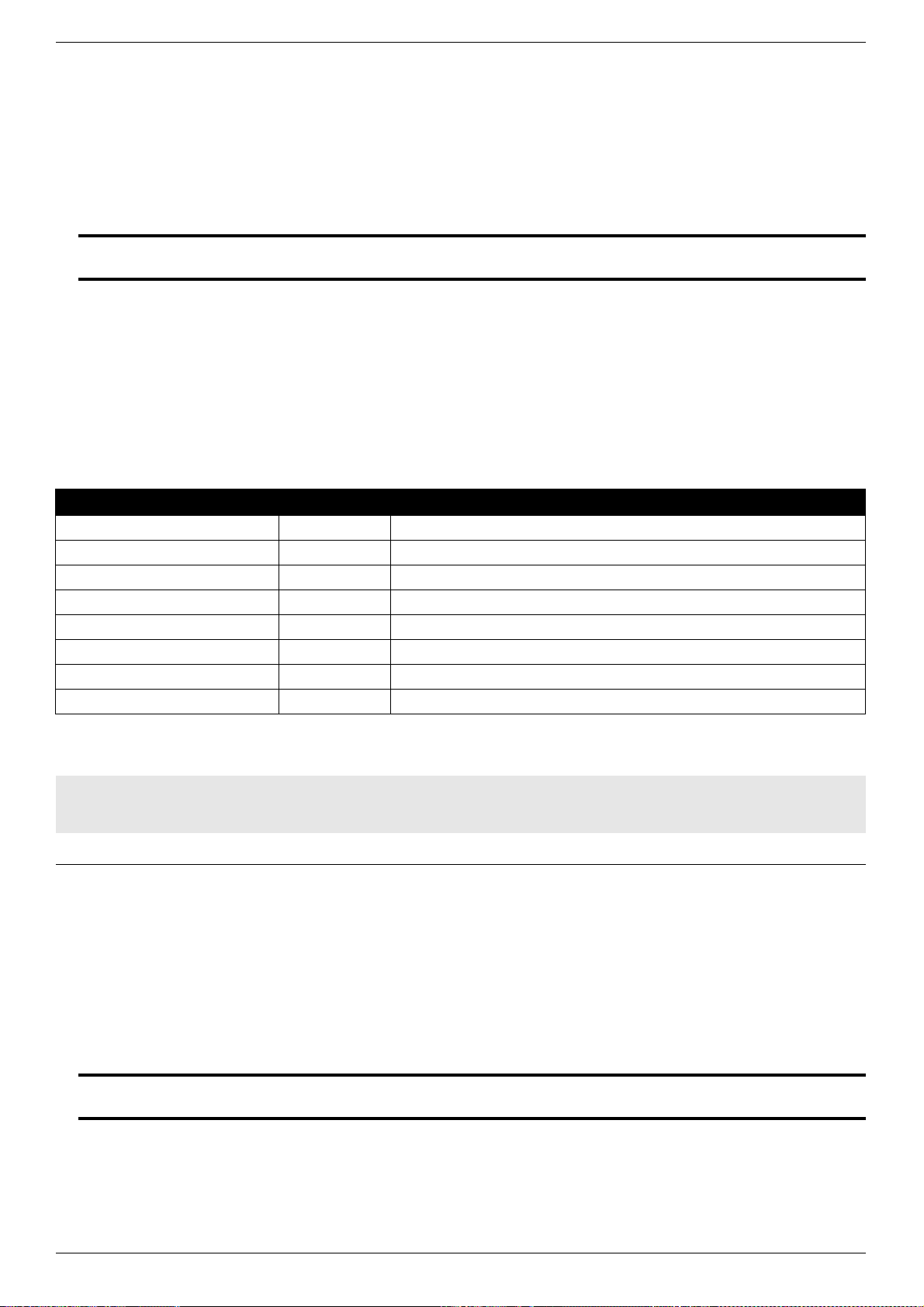
DXS-3600 Series 10GbE Layer 2/3 Switch CLI Reference Guide
585
60-3 logging console
This command is used to set the severity of logs that are allowed to be displayed on the console. The no format of the
command disable show log on console.
logging console LEVEL
no logging console
Parameters
60-4 logging trap
This command is used to set the severity of logs that are allowed to be send to the syslog server. The no format of the
command disable send log to syslog server.
logging trap LEVEL
no logging trap
Parameters
LEVEL Specifies the severity of log messages, 0 to 7. The name of the severity or the
numeral can be used.
Default
Debugging level.
Command Mode
Global Configuration Mode.
Command Default Level
Level: 15
Usage Guideline
When a log severity is set here, the log messages at or below that severity will be
displayed on the console.
The following table is description about the level:
Severity Level Description
Emergency 0 System is unusable.
Alert 1 Action must be taken immediately.
Critical 2 Critical conditions.
Error 3 Error conditions.
Warning 4 Warning conditions.
Notice 5 Normal but significant condition.
Information 6 Information messages.
Debug 7 Debug-level messages.
Example
This example shows how to set the severity of the log, that is allowed to be displayed
on the console, as 6:
DXS-3600-32S#configure terminal
DXS-3600-32S(config)#logging console informational
DXS-3600-32S(config)#
LEVEL Specifies the severity of log messages, 0 to 7. The name of the severity or the
numeral can be used.
Default
Informational level.
Command Mode
Global Configuration Mode.
Command Default Level
Level: 15

DXS-3600 Series 10GbE Layer 2/3 Switch CLI Reference Guide
586
60-5 logging source
This command is used to configure the source IP address of logs. The no format of the command cancel the specified
source’s configuration.
logging source {interface INTERFACE-ID | IP-ADDRESS}
no logging source
Parameters
60-6 logging facility
This command is used to configure the log device. The no format of the command restores it to the default device
value.
logging facility FACILITY-TYPE
no logging facility
Parameters
Usage Guideline
To send logs to the syslog server, execute first the global configuration command
logging server to configure syslog server. Then, execute logging trap to specify the
severity of logs to be sent. The show logging command displays the related setting
parameters and statistics of the log.
Example
This example shows how to enable logs at severity 6 to be sent to the syslog server
at address 10.90.90.4
DXS-3600-32S#configure terminal
DXS-3600-32S(config)#logging server 10.90.90.4
DXS-3600-32S(config)#logging trap 6
DXS-3600-32S(config)#
interface INTERFACE-ID Specifies the interface which IP address that will be used as source to send logs to
log server
IP-ADDRESS Specifies the source IPV4 address that will be used as source to send logs to log
server.
Default
None.
Command Mode
Global Configuration Mode.
Command Default Level
Level: 15
Usage Guideline
By default, the source address of the log messages sent to the syslog server is the
address of the sending interface. For easy tracing and management, this command
can be used to fix the source address of all log messages as an interface address,
so that the administrator can identify which device is sending the message through
the unique addresses.
Example
This example shows how to specify VLAN 1 as the source interface of the syslog
messages.
DXS-3600-32S#configure terminal
DXS-3600-32S(config)#logging source interface vlan 1
DXS-3600-32S(config)#
FACILITY-TYPE Specifies the Syslog device value.
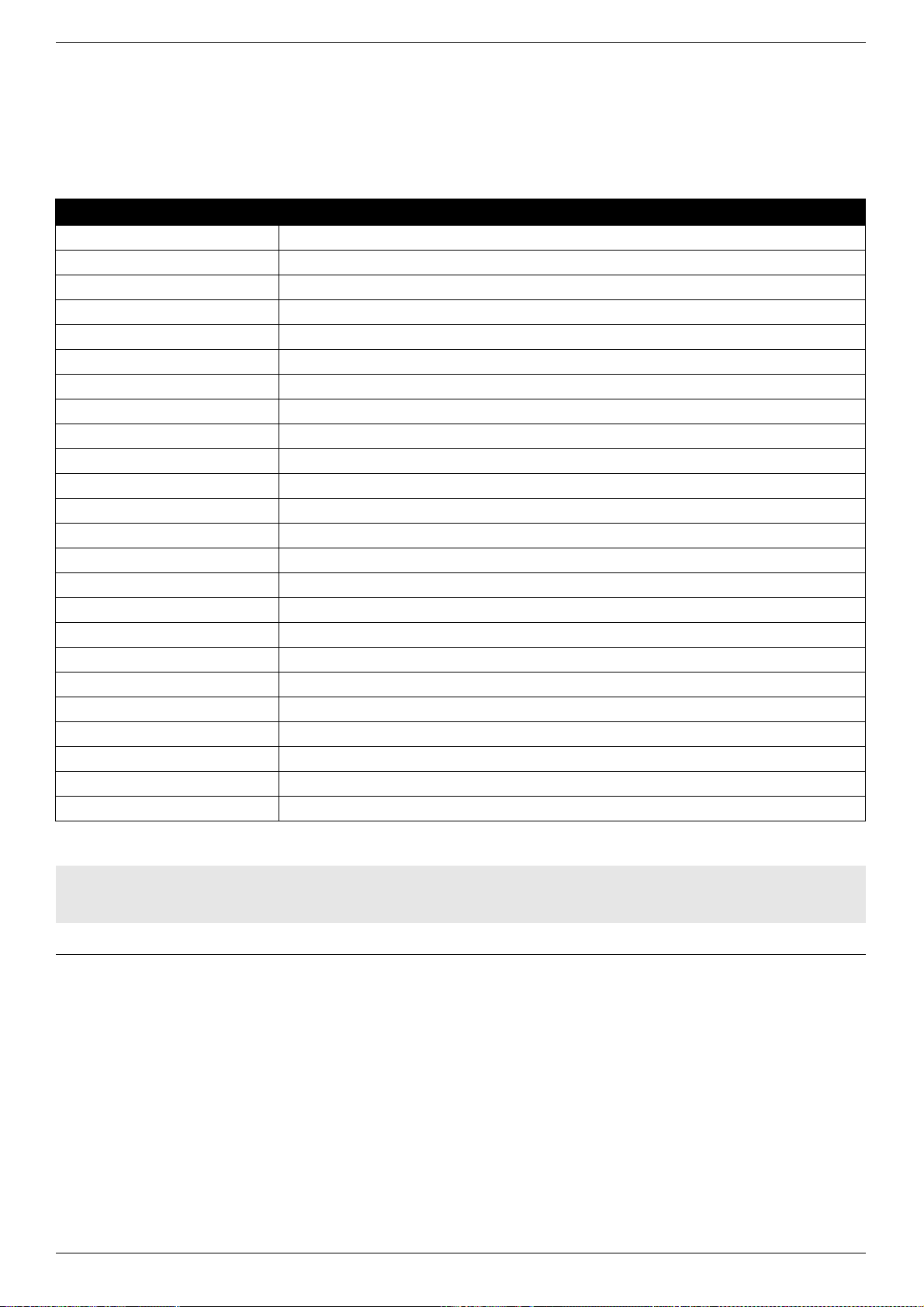
DXS-3600 Series 10GbE Layer 2/3 Switch CLI Reference Guide
587
60-7 logging count
This command is used to enable the log statistics function. The no format of the command deletes the log statistics and
disables the statistics function.
logging count
no logging count
Default
Local7.
Command Mode
Global Configuration Mode.
Command Default Level
Level: 15
Usage Guideline
A list of facility descriptions and their respective codes are listed below:
Numberical code Facility
0 Kernel messages
1 User-level messages
2 Mail system
3 System daemons
4 Security/authorization messages
5 Messages generated internally by syslogd
6 Line printer sub-system
7 Network news sub-system
8 UUCP sub-system
9 Clock daemon
10 Security/authorization messages
11 FTP daemon
12 NTP sub-system
13 Log audit
14 Log alert
15 Clock daemon
16 Local use 0 (local0)
17 Local use 1 (local1)
18 Local use 2 (local2)
19 Local use 3 (local3)
20 Local use 4 (local4)
21 Local use 5 (local5)
22 Local use 6 (local6)
23 Local use 7 (local7)
Example
This example shows how to set the facility as local1.
DXS-3600-32S#configure terminal
DXS-3600-32S(config)#logging facility local1
DXS-3600-32S(config)#
Parameters
None.
Default
By default, this option is disabled.
Command Mode
Global Configuration Mode.
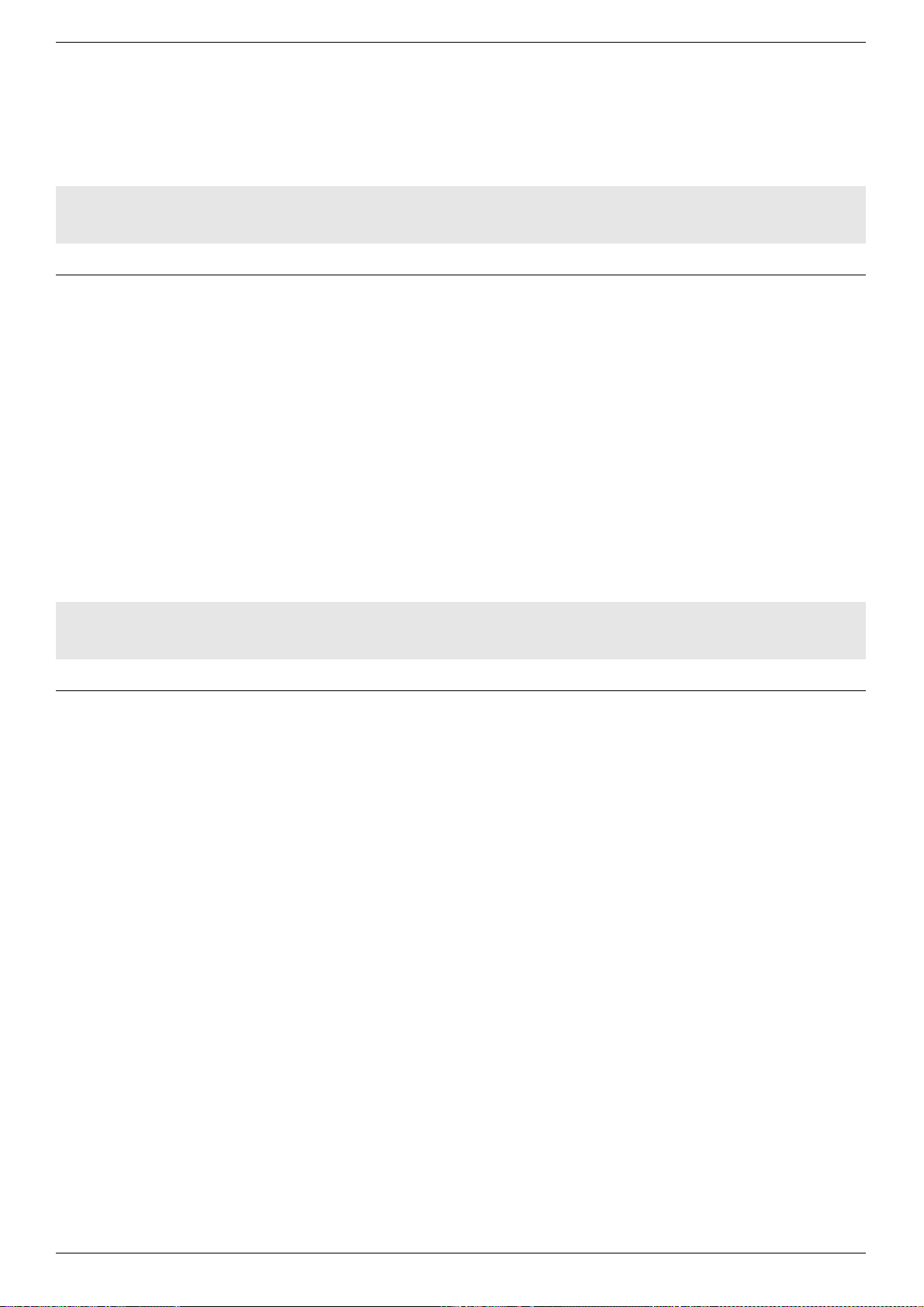
DXS-3600 Series 10GbE Layer 2/3 Switch CLI Reference Guide
588
60-8 clear logging
This command is used to clear the logs from the buffer.
clear logging
60-9 show logging
This command is used to display the logs in the buffer.
show logging
Command Default Level
Level: 15
Usage Guideline
This command enables the log statistics function. The statistics begins when the
function is enabled. If you run no logging count, the statistics function is disabled and
the statistics data is deleted.
Example
This example shows how to enable the log statistics function.
DXS-3600-32S#configure terminal
DXS-3600-32S(config)#logging count
DXS-3600-32S(config)#
Parameters
None.
Default
None.
Command Mode
Global Configuration Mode.
Command Default Level
Level: 15
Usage Guideline
This command clears the log packets from the memory buffer. You cannot clear the
statistics of the log packets.
Example
This example shows how to clear the log packets from the memory buffer.
DXS-3600-32S#configure terminal
DXS-3600-32S(config)#clear logging
DXS-3600-32S(config)#
Parameters
None.
Default
None.
Command Mode
EXEC Mode.
Command Default Level
Level: 15
Usage Guideline
This command only allows you to view the log files. You cannot use this command to
view other non-log files.
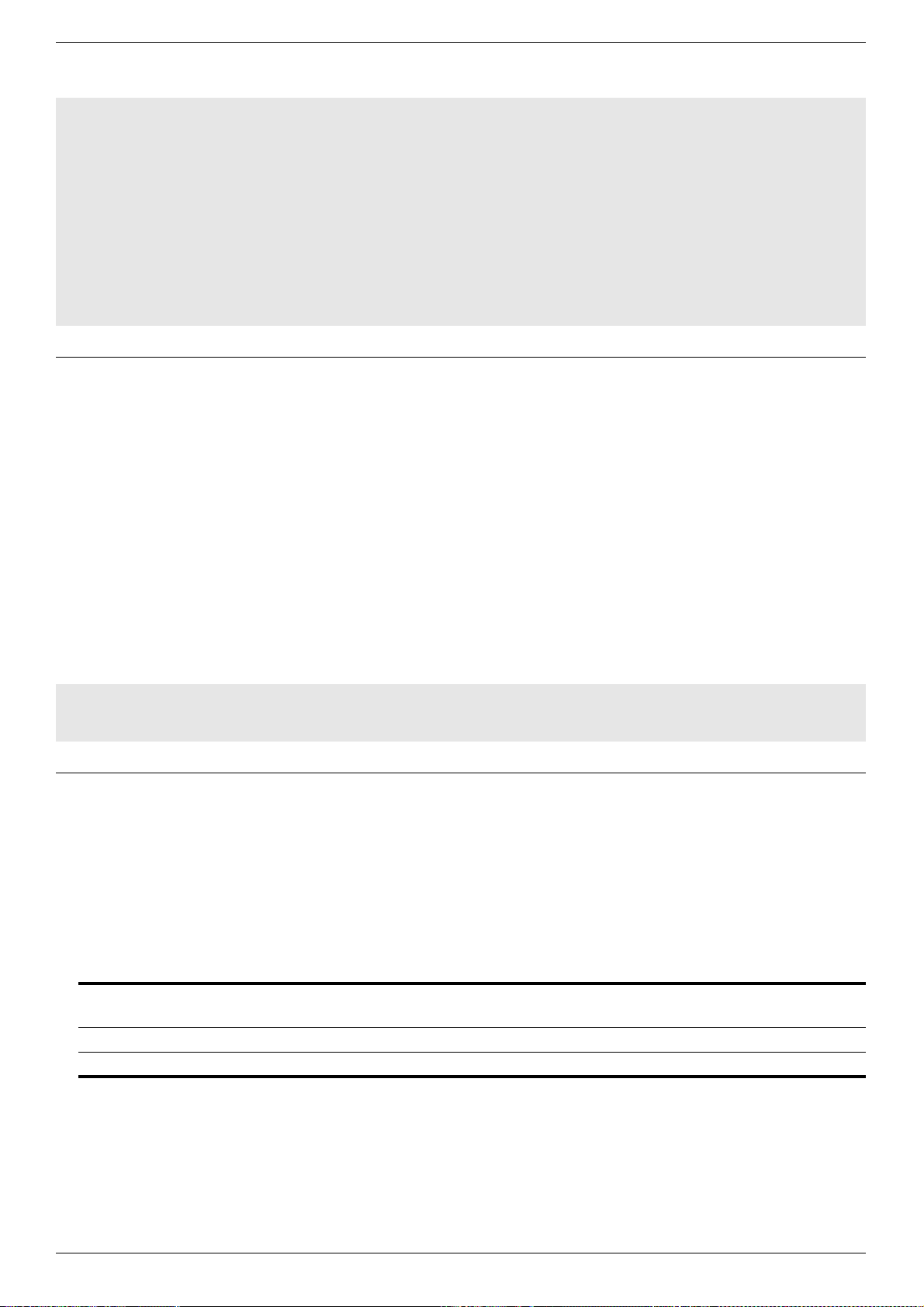
DXS-3600 Series 10GbE Layer 2/3 Switch CLI Reference Guide
589
60-10 show logging count
This command is used to show the log statistics.
show logging count
60-11 logging buffered
This command is used to set the memory buffer parameters for logs. The no form of the command disables recording
logs in memory buffer.
logging buffered [LEVEL] | [write-delay {SECONDS | INFINITE}]
no logging buffered
Parameters
Example
This example shows the result of the show logging command.
DXS-3600-32S#show logging
Syslog Logging: Enabled
Console Logging: Level Informational
Buffer Logging: Level Debugging
Trap Logging: Level Informational
Facility: local1
logging to 10.90.90.4
Logging File Write Delay: On_demand
Syslog Source IP Interface Configuration:
IP Interface : vlan1
IPv4 Address : 192.168.69.123
DXS-3600-32S#
Parameters
None.
Default
None.
Command Mode
EXEC Mode.
Command Default Level
Level: 15
Usage Guideline
To use the log packet statistics function, run logging count in the global configuration
mode. The show logging count can show the information of a log.
Example
This example shows the log statistics.
DXS-3600-32S#show logging count
Total logging Count: 0
DXS-3600-32S#
LEVEL Specifies the severity of log messages, 0 to 7. The name of the severity or the
numeral can be used.
SECONDS Specifies the minutes interval to write logs in the flash.
INFINITE Specifies that the logs are not recorded in the flash.
Default
Default level : Debugging(7).
Default will log to buffer and disable periodical writing of the logging buffer to FLASH.
Command Mode
Global Configuration Mode.
Command Default Level
Level: 15

DXS-3600 Series 10GbE Layer 2/3 Switch CLI Reference Guide
590
60-12 save log
This command is used to save the log.
save log
Usage Guideline
The memory buffer for the log is used in a recycled manner. That is, when it is full,
the oldest information will be overwritten. The content of the logging buffer will be
saved to the FLASH periodically if the interval time is specified, so the message can
be restored on reboot. To show the log information in the memory buffer, run show
logging at the privileged user level.
As lower values indicate higher levels, level 0 indicates the information of the highest
level. When the level of log information to be displayed on a specified device, the log
information is at or below the set level will not be displayed.
Example
This example shows how to disable record logs into flash.
DXS-3600-32S#configure terminal
DXS-3600-32S(config)#logging buffered write-delay infinite
DXS-3600-32S(config)#
Parameters
None.
Default
None.
Command Mode
Global Configuration Mode.
Command Default Level
Level: 15
Usage Guideline
As log entries are created and store in the DRAM, a log message may be lost while
powering down the switch. To avoid the loss of log entries, the administrator needs
save the log into the NVRAM via UI or use the periodical save command to save the
log to the NVRAM.
Example
This example shows the command of save log.
DXS-3600-32S#configure terminal
DXS-3600-32S(config)#save log
Saving all system logs to NV-RAM............. Done.
DXS-3600-32S(config)#
1 2011-12-23 17:35:27 INFO(6) System log saved to flash by console (Username
: Anonymous)
DXS-3600-32S(config)#
DXS-3600 Series 10GbE Layer 2/3 Switch CLI Reference Guide
591
TACACS+ Commands
61-1 tacacs-server host
This command is used to configure the IP address of TACACS+ server host. The no form of this command without
parameters is used to delete the TACACS+ server host. The no form of this command with the parameters is used to
restore the specified parameter to default value.
tacacs-server host ip-address [port integer] [timout integer] [key string]
no tacacs-server host ip-address [port | timout | key]
Parameters
61-2 tacacs-server key
This command is used to configure global password of TACACS+.
tacacs-server key string
no tacacs-server key
Parameters
ip-address Specifies the IP address of the TACACS+ server host.
port integer Specifies the TCP port used in TACACS+ communication. The range is 1 to 65535. If
unspecified, the port number defaults to 49.
timeout integer Specifies the timeout value of the TACACS+ host. The range is 1 to 1000s.
key string Specifies the shared keyword of the TACACS+ client and server. The maximum
length of the key is 254.
Default
No specified TACACS+ host.
Command Mode
Global Configuration Mode.
Command Default Level
Level: 15
Usage Guideline
To use TACACS+ to implement AAA security service, you must define TACACS+
secure server. You can define one or multiple TACACS+ secure servers by using
tacacs-server.
Example
This example shows how to define a TACACS+ secure server host.
DXS-3600-32S#configure terminal
DXS-3600-32S(config)#tacacs-server host 192.168.12.1
DXS-3600-32S(config)#
string Specifies the text of the shared password. The maximum length of the key is 254.
Default
No specified shared password.
Command Mode
Global Configuration Mode.
Command Default Level
Level: 15
Usage Guideline
The device and TACACS+ secure server communicates with each other successfully
on the basis of the shared password. Therefore, in order to make the device and
TACACS+ secure server communicate with each other, the same shared password
must be defined on both of them. When we need to specify different passwords to
every server, use key option in host command. We can set a key to all the servers
that have not set key option in global configuration mode.
DXS-3600 Series 10GbE Layer 2/3 Switch CLI Reference Guide
592
61-3 tacacs-server timeout
This command is used to configure the global timeout time waiting for the server when communicatin with TACACS+
server.
tacacs-server timeout seconds
no tacacs-server timeout
Parameters
61-4 show tacacs statistics
This command is used to show the interoperation condition with each TACACS+ server.
show tacacs statistics
Example
This example shows how to define the shared password of the TACACS+ secure
server as ‘aaa’.
DXS-3600-32S#configure terminal
DXS-3600-32S(config)#tacacs-server key aaa
DXS-3600-32S(config)#
seconds Specifies the timeout value used. The range is from 1 to 1000 seconds.
Default
5 seconds.
Command Mode
Global Configuration Mode.
Command Default Level
Level: 15
Usage Guideline
Use this command to adjust the timeout time of reply packet. When we need to
specify different timeout time to every server, use timeout option in host command.
We can set a timeout to all the servers that have not set timeout option in global
configuration mode.
Example
This example shows how to define the timeout time as 10 sec.
DXS-3600-32S#configure terminal
DXS-3600-32S(config)#tacacs-server timeout 10
DXS-3600-32S(config)#
Parameters
None.
Default
None.
Command Mode
Privileged EXEC Mode.
Command Default Level
Level: 15
Usage Guideline
Use this command to show the interoperation condition with each TACACS+ server.

DXS-3600 Series 10GbE Layer 2/3 Switch CLI Reference Guide
593
61-5 show tacacs-server configuration
This command is used to display the TACACS+ server configuration.
show tacacs-server configuration
Example
This example shows how to display all the server groups configured for TACACS+.
DXS-3600-32S#show tacacs statistics
TACACS+ Server: 192.168.12.1/49
Socket Opens: 0
Socket Closes: 0
Total Packets Sent: 0
Total Packets Recv: 0
Reference Count: 0
DXS-3600-32S#
Display Parameters Description
TACACS+ Server IP address of the TACACS+ server.
Socket Opens Number of successful TCP socket connections to the TACACS+ server.
Socket Closes Number of successfully closed TCP socket attempts.
Total Packets Sent Number of packets sent to the TACACS+ server.
Total Packets Recv Number of packets received from the TACACS+ server.
Reference Count Number of authentication requests from the TACACS+ server.
Parameters
None.
Default
None.
Command Mode
Privileged EXEC Mode.
Command Default Level
Level: 15
Usage Guideline
Use this command to show all TACACS+ server hosts.
Example
This example shows the output for the show TACACS+ server hosts command.
DXS-3600-32S#show tacacs-server configuration
IP-Address Port Key Timeout
-------------------------------------------------------------
192.168.12.1 49
Default Key:aaa
Default Timeout:10
1 TACACS+ server(s) in total
DXS-3600-32S#
Display Parameters Description
IP-Address IP address of TACACS+ server host.
Port TCP port used in TACACS+ communication.
Key Shared keyword of TACACS+ client and server.
Timeout Timeout time of TACACS+ host, the unit is seconds.
Default Key Global password of TACACS+.

DXS-3600 Series 10GbE Layer 2/3 Switch CLI Reference Guide
594
Default Timeout The global timeout time waiting for the server when communicating with TACACS+
server.
Display Parameters Description

DXS-3600 Series 10GbE Layer 2/3 Switch CLI Reference Guide
595
TELNET Commands
62-1 ip telnet server enable
This command is used to enable the TELNET server on the switch. Use the no form of this command to disable the
TELNET server on the switch.
ip telnet server enable
no ip telnet server enable
62-2 telnet
This command is used to TELNET to a remote server and manage it through the TELNET protocol.
telnet <ip-address> [port]
telnet [vrf <string 1-12>] <ip-address> [port]
Parameters
62-3 show ip telnet server
This command is used to display the TELNET server information.
show ip telnet server
Parameters
None.
Default
By default the TELNET server is enabled.
Command Mode
Global Configure Mode.
Command Default Level
Level: 8
Usage Guideline
This command enables the TELNET server service on the switch. It allows
communication with and management of the switch using the TELNET protocol.
Example
This example shows how to enable the TELNET server on the switch.
DXS-3600-32S#configure terminal
DXS-3600-32S(config)#ip telnet server enable
DXS-3600-32S(config)#
vrf <string 1-12> Specifies the VRF of the TELNET server. If the parameter is not specified, it
indicates the global routing forward space.
ip-address Specifies the IPv4 address of the destination end station.
port Specifies the TCP port number of the TELNET server.
Default
None.
Command Mode
Privileged EXEC Mode.
Command Default Level
Level: 2
Usage Guideline
This command is used to TELNET to a remove server and manage it through the
TELNET protocol
Example
This example shows how to TELNET to a remove server.
DXS-3600-32S#telnet 10.90.90.91
Parameters
None.

DXS-3600 Series 10GbE Layer 2/3 Switch CLI Reference Guide
596
Default
None.
Command Mode
Privileged Mode.
Command Default Level
Level: 8
Usage Guideline
This command is used to display the TELNET server information.
Example
This example shows how to display the TELNET server information.
DXS-3600-32S#show ip telnet server
Server State : Enabled
DXS-3600-32S#

DXS-3600 Series 10GbE Layer 2/3 Switch CLI Reference Guide
597
Time Range Commands
63-1 time-range
This command is used to enter the Time Range configuration mode in the global configuration mode. To delete a time
range, use the no to form of this command.
time-range <range_name 32>
no time-range <range_name 32>
Parameters
63-2 periodic
This command is used to configure the time range.
periodic <daylist> HH:MM to HH:MM
Parameters
range_name 32 Specifies the time range name string in the range of 1 to 32.
Default
None.
Command Mode
Global Configuration Mode.
Command Default Level
Level: 8
Usage Guideline
In the time range configuration mode, the time range can be configured periodically.
Use the no time-range command to delete the time range. If the time range is
binded to an ACL profile or a PoE port (if PoE is supported), the deletion will fail.
Example
This example shows how to enter time range configure mode.
DXS-3600-32S#configure terminal
DXS-3600-32S(config)#time-range a
DXS-3600-32S(config-time-range)#
Example
This example shows how to delete a time range.
DXS-3600-32S#configure terminal
DXS-3600-32S(config)#no time-range a
Success
DXS-3600-32S(config)#
daylist Specifies the day list string used. Options to choose from are sun, mon, tue, wen,
thu, fri and sat.
HH:MM Specifies the start or end time used. The range is from 00:00 to 23:59.
Default
The maximum number of the time range is 64.
Command Mode
Time Range Configuration Mode.
Command Default Level
Level: 8
Usage Guideline
This command configures the time range. If the time range already exists, this
command will modify the configuration. If not, this command will add a time range.
To verify your configuration, use show time-range.

DXS-3600 Series 10GbE Layer 2/3 Switch CLI Reference Guide
598
63-3 show time-range
This command is used to display all existing time ranges.
show time-range
Example
This example shows how to configure a new time range called time1.
DXS-3600-32S#configure terminal
DXS-3600-32S(config)#time-range time1
DXS-3600-32S(config-time-range)#periodic sun-tue 1:00 to 2:00
Success
DXS-3600-32S(config-time-range)#
Parameters
None.
Default
None.
Command Mode
Global Configuration Mode.
Command Default Level
Level: 4
Usage Guideline
None.
Example
This example shows how to display all existing time range.
DXS-3600-32S#show time-range
Time Range Information
-------------------------
Range Name : time1
Weekdays : Sun,Mon,Tue
Start Time : 01:00
End Time : 02:00
Total Entries :1
DXS-3600-32S#

DXS-3600 Series 10GbE Layer 2/3 Switch CLI Reference Guide
599
Traffic Segmentation Commands
64-1 switchport protected unidirectional
This command is used to enable the interface isolated to a specified interface list for unidirectional protected. Use the
no form of the command to disable the interface isolated to a specified interface list.
switchport protected unidirectional {interface-type interface-list}
no switchport protected unidirectional [interface-type interface-list]
Parameters
64-2 show protected-ports
This command is used to display the switch port’s protected configuration information.
show protected-ports interface interface-id
Parameters
interface-type Specifies the interface type, such as fastEthernet, gigabitEthernet and
tenGigabitEthernet.
interface-list Specifies the interface list.
Default
The main interface is not isolated.
Command Mode
Interface Configuration Mode.
Command Default Level
Level: 15
Usage Guideline
After the interface is isolated to a specified interface, the interface can not switch on
L2 and route on L3 to the specified interface. But the specified interface to it has no
limit.
If not specified, all interfaces will be included.
Use the show protected-ports command to display unidirectional configuration.
Example
This example shows how to enable the port 1 isolated to port 2-6.
DXS-3600-32S#configure terminal
DXS-3600-32S(config)#interface tenGigabitEthernet 1/0/1
DXS-3600-32S(config-if)#switchport protected unidirectional tenGigabitEthernet 1/0/2-1/0/6
Success
DXS-3600-32S(config-if)#
interface interface-id Displays the specified interface’s unidirectional isolated information.
Default
None.
Command Mode
Privileged Mode.
Command Default Level
Level: 15
Usage Guideline
This command is used to display the switch port’s protected configuration
information.

DXS-3600 Series 10GbE Layer 2/3 Switch CLI Reference Guide
600
Example
This example shows how to display the switch port’s protected unidirectional
information for interface 1.
DXS-3600-32S#show switchport protected interface tenGigabitEthernet 1/0/1
Function Version: 1.01
Interface Unidirectional Portlist
--------- ---------------------------------------------------------
TenGigabitEthernet1/0/1 1:2, 1:4-1:26
DXS-3600-32S#

DXS-3600 Series 10GbE Layer 2/3 Switch CLI Reference Guide
601
Upgrade and Maintenance Commands
65-1 copy
This command is used to upgrade and maintain the switch by use of the TFTP protocol for uploads and downloads.
copy flash: filename tftp://location/filename
copy tftp://location/filename flash: filename
Parameters
65-2 boot system
This command is used to configure the specific firmware as the boot up image.
boot system flash filename
Parameters
filename Specifies the file name used.
//location/filename Specifies the file's location or the server IP address.
Default
None.
Command Mode
Privileged EXEC Mode.
Command Default Level
Level: 15
Usage Guideline
If the file is transmitted successfully, show the length of the transmitted file.
Otherwise, show the failure information. Only configuration and firmware files can be
transmitted by TFTP.
Example
This example shows how to download a firmware named “firmware.had” from a
TFTP server.
DXS-3600-32S#copy tftp: //192.168.0.27/firmware.had flash: run.had
Address of remote host [192.168.0.27]
Source filename [firmware.had]
Destination filename [run.had]
Accessing tftp://192.168.0.27/ firmware.had...
Transmission start...
Transmission finished, file length 5156864 bytes.
Please wait, programming flash... Done
DXS-3600-32S#
Example
This example shows how to upload a firmware to a TFTP server.
DXS-3600-32S#copy flash: run.had tftp: //192.168.0.27/firmware.had
Source filename [run.had]
Address of remote host [192.168.0.27]
Destination filename [firmware.had]
Accessing tftp://192.168.0.27/firmware.had...
Transmission start...
Transmission finished, file length 5156864 bytes.
DXS-3600-32S#
filename Specifies the file name used.

DXS-3600 Series 10GbE Layer 2/3 Switch CLI Reference Guide
602
65-3 show bootup
This command is used to display the boot up file information.
show bootup
Default
None.
Command Mode
Global Configuration Mode.
Command Default Level
Level: 15
Usage Guideline
By default, the switch attempts to automatically boot the system using the
information in the BOOT environment variable. If this variable is not set, the switch
attempts to load and execute the first executable image.
Example
This example shows how to configure the ‘firmware.had’ file as the boot up image.
DXS-3600-32S#configure terminal
DXS-3600-32S(config)#boot system flash firmware.had
DXS-3600-32S(config)#
Parameters
None.
Default
None.
Command Mode
Privileged EXEC Mode.
Command Default Level
Level: 3
Usage Guideline
Used to display the boot up file information.
Example
This example shows how to display the boot up file information.
DXS-3600-32S#show bootup
Bootup Firmware : /c:/runtime.had
Bootup Configuration : /c:/y
DXS-3600-32S#

DXS-3600 Series 10GbE Layer 2/3 Switch CLI Reference Guide
603
Virtual LAN (VLAN) Commands
66-1 vlan
This command is used to create VLANs and enter the VLAN configuration mode. Use the no vlan configuration
command to remove VLANs.
vlan VLAN-ID [, | -]
no vlan VLAN-ID [, | -]
Parameters
VLAN-ID Specifies the ID of the VLAN to be created, removed or configured. The valid VLAN
ID range is from 1 to 4094. The default VLAN with VLAN ID 1 can not be removed.
, Specifies a series of VLANs, or separate a range of VLANs from a previous range.
No space is required before and after the comma.
- (Optional) Specifies a range of VLANs. No space is required before and after the
hyphen.
Default
VLAN ID 1 exists in the system as the default VLAN.
Command Mode
Global Configuration Mode.
Command Default Level
Level: 12
Usage Guideline
This command can be used to create VLANs. Entering the vlan command with a
VLAN ID enters VLAN configuration mode. Entering the VLAN ID of an existing
VLAN does not create a new VLAN, but allows the user to modify VLAN parameters
for the specified VLAN. When the user enters the VLAN ID of a new VLAN, the
VLAN will be automatically created. If the new VLAN is a port allowed VLAN, the port
will join to the new VLAN automatically.
The user can use the no vlan command to remove VLANs. The default VLAN
cannot be removed. The dynamic VLAN that is created through GVRP cannot be
removed through this command. If the VLAN is used as ERPS R-APS VLAN,
RSPAN VLAN, voice VLAN, subnet VLAN or MAC-based VLAN, it cannot be
removed too.
Removing VLAN doesn’t remove the association of the VLAN with its static member
ports. Once the VLAN is re-created, these ports will join into it automatically.
The learned dynamic FDB entries in the removed VLAN will be cleared. The static
FDB entries in this VLAN will not be removed.
If the removed VLAN is a private VLAN, the configuration for the private VLAN will be
cleared.
If the removed VLAN is a port’s access VLAN, the port’s access VLAN will be reset
to VLAN 1.
If the VLAN is used as protocol VLAN or VLAN translation, removing it doesn’t affect
the VLAN assignment.
If the VLAN is used as super VLAN or L3 interface, removing it will lead to these
functions become unavailable until this VLAN is re-created.

DXS-3600 Series 10GbE Layer 2/3 Switch CLI Reference Guide
604
66-2 name
This command is used to specify the name of a VLAN. Use the no name command to reset the VLAN name to the
default VLAN name.
name VLAN-NAME
no name
Parameters
66-3 switchport mode
This command is used to specify the VLAN mode for the port. Use no switchport command to reset the VLAN mode
to default setting.
switchport mode {access | hybrid | trunk | dot1q-tunnel}
no switchport mode
Parameters
Example
In the following example, the user adds a new VLAN, assigning the new VLAN with
the VLAN IDs 1000 to 1005.
DXS-3600-32S#configure terminal
DXS-3600-32S(config)#vlan 1000-1005
DXS-3600-32S(config-vlan)#
Example
In the following example, the user removes the existing VLANs with the VLAN IDs.
DXS-3600-32S#configure terminal
DXS-3600-32S(config)#no vlan 1000-1005
DXS-3600-32S(config)#
VLAN-NAME Specifies the VLAN name. This name is an ASCII string from 1 to 32 characters that
must be unique within the administrative domain. The syntax is a general string that
does not allow spaces.
Default
The default VLAN name is VLANxxxx, where xxxx represents four numeric digits
(including the leading zeros) that are equal to the VLAN ID.
Command Mode
VLAN Configuration Mode.
Command Default Level
Level: 12
Usage Guideline
The user can use the name VLAN-NAME VLAN configuration command to specify a
VLAN name. The VLAN name length must be between 1 and32 characters, and it
must be unique within the administrative domain.
Example
In the following example, the user configures the VLAN name of VLAN 1000 to be
“admin-vlan”.
DXS-3600-32S#configure terminal
DXS-3600-32S(config)#vlan 1000
DXS-3600-32S(config-vlan)#name admin-vlan
DXS-3600-32S(config-vlan)#
access Specifies the port as an access port.
hybrid Specifies the port as a hybrid port.
trunk Specifies the port as a trunk port.

DXS-3600 Series 10GbE Layer 2/3 Switch CLI Reference Guide
605
66-4 switchport access vlan
This command is used to specify the access VLAN for the interface. Use no switchport access vlan interface
command to reset to default setting.
switchport access vlan VLAN-ID
no switchport access vlan
Parameters
dot1q-tunnel Specifies the port as a dot1q-tunnel port.
Default
Access mode.
Command Mode
Interface Configuration Mode.
Command Default Level
Level: 12
Usage Guideline
The valid interfaces for this command are physical ports or link aggregation groups.
When the port changes the VLAN mode, the VLAN membership setting related to
the previous mode will be lost. The PVID is set to default value too. If setting the port
mode to access or dot1q tunnel, the GVRP status of the port will be disabled.
The user can specify the access VLAN for an access port. On an access port, only
untagged packets are processed, they are transmitted and received on the access
VLAN. The user can specify multiple VLANs for a trunk port. Packets on a trunk port
are received and transmitted on trunk VLANs in tagged form. The user can specify
multiple VLANs for a hybrid port. Packets on a hybrid can be received and
transmitted in tagged form or untagged form.
Creating a link aggregation doesn’t need the VLAN setting of its member ports are
same as. The VLAN setting of the new link aggregation is default value. The VLAN
setting of member ports become inactive. Once a member port is removed from the
link aggregation group, its VLAN setting becomes active again.
Example
This example shows how to set an interface port 1 as a trunk port.
DXS-3600-32S#configure terminal
DXS-3600-32S(config)#interface tenGigabitEthernet 1/0/1
DXS-3600-32S(config-if)#switchport mode trunk
DXS-3600-32S(config-if)#
VLAN-ID Specifies the access VLAN for the interface.
Default
VLAN 1.
Command Mode
Interface Configuration Mode.
Command Default Level
Level: 12
Usage Guideline
The command can only be configured on physical ports or link aggregation groups
that are set to access mode or dot1q-tunnel mode.
This command sets the access VLAN for an access port. The port becomes an
untagged member of access VLAN and the port’s PVID will also be changed to the
access VLAN. If the specified access VLAN does not exist, it will be created
automatically. Only one access VLAN can be specified. The succeeding command
overwrites the previous command.

DXS-3600 Series 10GbE Layer 2/3 Switch CLI Reference Guide
606
66-5 switchport trunk allowed vlan
This command is used to configure the VLANs that will be allowed to receive and send traffic on the specified interface
in a tagged format. Use the no switchport trunk allowed vlan command to reset the VLAN membership of the port.
switchport trunk allowed vlan {all | {add | remove } VLAN-ID [, | -]}
no switchport trunk allowed vlan
Parameters
The switchport access vlan command can also be used to configure the tunnel
VLAN for a Dot1q-tunnel port. Removing the VLAN that is used as a port’s access
VLAN will lead to the port’s access VLAN to reset to the default VLAN.
Example
This example shows how to set an interface port 1 to access mode with access
VLAN 1000.
DXS-3600-32S#configure terminal
DXS-3600-32S(config)#interface tenGigabitEthernet 1/0/1
DXS-3600-32S(config-if)#switchport mode access
DXS-3600-32S(config-if)#switchport access vlan 1000
DXS-3600-32S(config-if)#
all Specifies to add all VLANs to the allowed VLAN list.
add Specifies to add the specified VLAN list to the allowed VLAN list.
remove Specifies to remove the specified VLAN list from the allowed VLAN list.
VLAN-ID Specifies the VLAN list that will be added or removed from.
, (Optional) Specifies a series of VLANs, or separate a range of VLANs from a
previous range. No space is required before and after the comma.
- (Optional) Specifies a range of VLANs. No space is required before and after the
hyphen.
Default
By default a port that is set to trunk mode allows all VLANs.
Command Mode
Interface Configuration Mode.
Command Default Level
Level: 12
Usage Guideline
The command can only be configured on physical ports or link aggregation groups
that are set to trunk mode.
If a trunk port is allowed all VLANs, the traffic of all VLANs can be transmitted over it.
Entering the switchport trunk allowed vlan command to restrict the traffic of some
VLANs from passing the trunk port. A trunk port is a tagged member of a VLAN if the
VLAN is existed and it is in the allowed VLAN list of this port. If an allowed VLAN is
created at later, the trunk port joins to it automatically.
Using no switchport trunk allowed-vlan command resets the allowed VLAN list of
the trunk port to default.
Example
This example shows how to configure an interface port 1 allowed VLAN list to 1-
1000.
DXS-3600-32S#configure terminal
DXS-3600-32S(config)#interface tenGigabitEthernet 1/0/1
DXS-3600-32S(config-if)#switchport mode trunk
DXS-3600-32S(config-if)#switchport trunk allowed vlan add 1-1000
DXS-3600-32S(config-if)#

DXS-3600 Series 10GbE Layer 2/3 Switch CLI Reference Guide
607
66-6 switchport hybrid allowed vlan
This command is used to specify if the port will be a tagged or untagged member of the specified VLAN for a hybrid
port. Use the no switchport hybrid allowed vlan command to reset the membership.
switchport hybrid allowed vlan {add {tagged | untagged} | remove} VLAN-ID [, | -]
no switchport hybrid allowed vlan
Parameters
66-7 switchport native vlan
This command is used to specify the native VLAN (PVID) of a trunk or hybrid mode interface. Use the no switchport
native vlan command to reset to the native VLAN ID to the default setting.
switchport native vlan VLAN-ID
no switchport native vlan
VLAN-ID Specifies the VLAN to add or remove the VLAN membership from.
add Specifies the port will be added into the specified VLAN(s).
remove Specifies the port will be removed from the specified VLAN(s).
tagged Specifies the port as a tagged member of the specified VLAN(s).
untagged Specifies the port as an untagged member of the specified VLAN(s).
, (Optional) Specifies a series of VLANs, or separate a range of VLANs from a
previous range. Enter a space before and after the comma.
- (Optional) Specifies a range of VLANs. Enter a space before and after the hyphen.
Default
By default, no VLAN memberships are configured for a hybrid port.
Command Mode
Interface Configuration Mode.
Command Default Level
Level: 12
Usage Guideline
The command can only be configured on physical ports or port-channels that are set
to hybrid mode or dot1q-tunnel mode. The command can be used to setting the
VLAN membership of a hybrid port. If the port has already been the tagged member
of a VLAN, adding the VLAN into the port untagged membership VLAN will lead to
the port becomes its untagged member, and vice versa. You cannot add a port into
its forbidden membership VLAN.
Use no switchport hybrid allowed vlan command all VLAN membership will be
removed, and the port will reset to default VLAN as untagged member. The port
remains in hybrid mode. The switchport hybrid allowed vlan command can also
be used to specify the VLAN membership for a dot1q-tunnel port.
The configuration doesn’t need the specified VLAN exist. Once the VLAN is created,
the interface will join to the VLAN automatically.
Example
In the following example, the user configures interface port 1 to be a tagged member
of VLAN 1000, and an untagged member of VLAN 2000 & 3000.
DXS-3600-32S#configure terminal
DXS-3600-32S(config)#interface tenGigabitEthernet 1/0/1
DXS-3600-32S(config-if)#switchport mode hybrid
DXS-3600-32S(config-if)#switchport hybrid allowed vlan add tagged 1000
DXS-3600-32S(config-if)#switchport hybrid allowed vlan add untagged 2000,3000
DXS-3600-32S(config-if)#

DXS-3600 Series 10GbE Layer 2/3 Switch CLI Reference Guide
608
Parameters
66-8 acceptable-frame
This command is used to set acceptable frame type of a port. The default acceptable frame type is admit-all.
acceptable-frame {tagged-only | untagged-only | admit-all}
Parameters
VLAN-ID Specifies the native VLAN ID for the trunk or hybrid interface.
Default
The default is VLAN 1.
Command Mode
Interface Configuration Mode.
Command Default Level
Level: 12
Usage Guideline
This command can only be configured on physical ports or link aggregation groups
that set to trunk or hybrid mode. This command is used to set the native VLAN
(PVID) of a trunk or hybrid port.
An interface can be specified with only one native VLAN. The succeeding command
overwrites the previous command.
The configuration doesn’t need the specified VLAN exist. For making the port join to
its native VLAN, the user shall add the native VLAN into its allowed VLAN. If the port
mode is trunk, the port will join to its native VLAN as untagged member. If the port
mode is hybrid, user can set its native VLAN as tagged or untagged.
Example
In the following example, the user configures interface port 1 to become a trunk
interface and configure its native VLAN to 20.
DXS-3600-32S#configure terminal
DXS-3600-32S(config)#interface tenGigabitEthernet 1/0/1
DXS-3600-32S(config-if)#switchport mode trunk
DXS-3600-32S(config-if)#switchport native vlan 20
DXS-3600-32S(config-if)#
tagged-only Specifies that only tagged frames will be accepted by the interface.
untagged-only Specifies that only untagged frames will be accepted by the interface.
admit-all Specifies that all frames will be accepted by the interface.
Default
The default acceptable frame setting is admit-all.
Command Mode
Interface Configuration Mode.
Command Default Level
Level: 12
Usage Guideline
The valid interfaces for this command are physical port or link aggregation groups.
The acceptable-frame interface command can be used to set the acceptable frame
type for an interface. If the acceptable frame type is set to tagged-only, only tagged
incoming packets will be received by the interface and untagged packets will be
dropped. If specifying untagged-only, only untagged packets will be received and
tagged packets will be dropped. If specifying admit-all, the interface will receive all
packets.
The access port only accepts untagged packets, no matter its acceptable-frame
type.

DXS-3600 Series 10GbE Layer 2/3 Switch CLI Reference Guide
609
66-9 ingress-checking
This command is used to enable the ingress checking of the received frames on a port. Use the no ingress-checking
interface command to disable the ingress checking function.
ingress-checking
no ingress-checking
66-10 mac-base (vlan)
This command is used to create a MAC-based VLAN classification entry. Use the no mac-base command to remove a
MAC-based VLAN classification entry.
mac-base MAC-ADDRESS [priority COS-VALUE]
no mac-base MAC-ADDRESS
Parameters
Example
In the following example, the user sets the acceptable frame type to be tagged-only
on port 1.
DXS-3600-32S#configure terminal
DXS-3600-32S(config)#interface tenGigabitEthernet 1/0/1
DXS-3600-32S(config-if)#acceptable-frame tagged-only
DXS-3600-32S(config-if)#
Parameters
None.
Default
By default, ingress checking is enabled.
Command Mode
Interface Configuration Mode.
Command Default Level
Level: 12
Usage Guideline
The valid interfaces for this command are physical ports or link aggregation groups.
You can use the ingress-checking interface command to enable ingress checking
on interfaces. If ingress checking is enabled, if the port is not member port of the
VLAN that has been classified for the received packet, the packet will be dropped.
The user can use the no ingress-checking interface command to disable this
function on a port.
Example
This example shows how to set ingress checking to enable of port 1.
DXS-3600-32S#configure terminal
DXS-3600-32S(config)#interface tenGigabitEthernet 1/0/1
DXS-3600-32S(config-if)#ingress-checking
DXS-3600-32S(config-if)#
MAC-ADDRESS Specifies the MAC address for the entry.
priority COS-VALUE Specifies the priority for the entry. The value is a number from 0 to 7, if the priority is
not specified, the default value is 0.
Default
No MAC-based VLAN ID classification entries exist.
Command Mode
VLAN Configuration Mode.
Command Default Level
Level: 12
DXS-3600 Series 10GbE Layer 2/3 Switch CLI Reference Guide
610
66-11 subnet-base (vlan)
This command is used to specify subnet-based VLAN ID assignment entry for un-tagged incoming packets. Use the no
subnet-base command to remove a subnet-based VLAN ID assignment entry.
subnet-base {NETWORK-PREFIX /PREFIX-LENGTH | IPV6-NETWORK-PREFIX /PREFIX-LENGTH} [priority
COS-VALUE]
no subnet-base {NETWORK-PREFIX /PREFIX-LENGTH | IPV6-NETWORK-PREFIX /PREFIX-LENGTH}
Parameters
Usage Guideline
The user can use the mac-base command in VLAN configuration mode to create the
MAC entry that will be classified to the MAC based VLAN. If MAC based VLAN
entries are configured, the packet received by the switch regardless of the incoming
port that have a source MAC address matching an the entry will be classified to the
corresponding MAC-based VLAN. The maximum number of MAC-based VLAN
assignment entry is project dependent.
The precedence to classify the VLAN for an untagged packet is
MAC-based > Subnet-based > Protocol VLAN > Port-based VLAN
The user should use the switchport hybrid allowed vlan command to set the
VLAN membership for the MAC-based VLAN.
Example
This example shows how to create a MAC-based VLAN entry for the MAC address
00-80-cc-00-00-11.
DXS-3600-32S#configure terminal
DXS-3600-32S(config)#vlan 101
DXS-3600-32S(config-vlan)#mac-base 00-80-cc-00-00-11 priority 4
DXS-3600-32S(config-vlan)#
NETWORK-PREFIX /
PREFIX-LENGTH
Specifies the network prefix and the prefix length in the form of A.B.C.D/x
IPV6-NETWORK-PREFIX /
PREFIX-LENGTH
Specities the IPv6 network prefix and the prefix length in the form of x:x:x:x:x:x:x:x/n.
The prefix length of IPv6 network address shall not greater than 64 bits.
priority COS-VALUE Specifies the priority for the entry. The value is a number from 0 to 7, if the priority is
not specified, the default value is 0.
Default
No subnet-based VLAN.
Command Mode
VLAN Configuration Mode.
Command Default Level
Level: 12
Usage Guideline
A subnet VLAN entry is an IP subnet-based VLAN classification rule. If an untagged
or priority-tagged IP packet is received on a port, its source IPv4 address or the
upper 64 bits of source IPv6 address will be used to match the subnet VLAN entries.
If the source IP matches the subnet of an entry, the packet will be classified to the
VLAN of this entry. If the packet is untagged, the priority will be picked up from it too.
For priority-tagged packet, its priority will not change. The number of subnet-based
VLAN entries is project dependent.
The precedence to classify an untagged packet is
MAC-based > Subnet-based > Protocol VLAN > Port-based VLAN
The user should use the switchport hybrid allowed vlan command to set the
VLAN membership for the subnet-based VLAN user.
DXS-3600 Series 10GbE Layer 2/3 Switch CLI Reference Guide
611
66-12 show vlan
This command is used to display the parameters for all configured VLANs or one VLAN (if the VLAN ID or name is
specified) on the switch.
show vlan [VLAN-ID [, | -] | interface [INTERFACE-ID [, | -]] | subnet-base | mac-base]
Parameters
Example
In the following example, the user creates a subnet-based VLAN entry for VLAN
100, specifying the subnets 20.0.1.0/8, 192.0.1.0/8 and 3ffe:22:33:44::55/64.
DXS-3600-32S#configure terminal
DXS-3600-32S(config)#vlan 100
DXS-3600-32S(config-vlan)#subnet-base 20.0.1.0/8
DXS-3600-32S(config-vlan)#subnet-base 192.0.1.0/8 priority 4
DXS-3600-32S(config-vlan)#subnet-base 3ffe:22:33:44::55/64
DXS-3600-32S(config-vlan)#
VLAN-ID (Optional) Displays information about a signal VLAN identified by VLAN ID number.
The VLAN ID range is 1 to 4094. Separate nonconsecutive VLAN-ID with a comma;
use a hyphen to designate a range of VLAN-ID.
interface (Optional) Displays the port PVID, ingress checking, acceptable frame type
information.
INTERFACE-ID Specifies the port to display.
, (Optional) Specifies a series of ports, or separate a range of ports from a previous
range. No space before and after the comma.
- (Optional) Specifies a range of ports. No space before and after the hyphen.
subnet-base (Optional) Displays the subnet-based VLAN related configuration.
mac-base (Optional) Displays the mac-based VLAN related configuration.
Default
None.
Command Mode
EXEC Mode.
Command Default Level
Level: 3
Usage Guideline
The user can use the show vlan command to display the current VLAN status. The
user can display the VLAN list using the show vlan command. The user can display
a specific VLAN entry by specifying a VLAN-ID. The user can use the show vlan
interface command to show port related VLAN information, such as port PVID,
ingress checking, and acceptable frame type information.
If no optional keywords are specified, all of the VLAN configurations will be
displayed.

DXS-3600 Series 10GbE Layer 2/3 Switch CLI Reference Guide
612
Example
This example displays all the current VLAN entries.
DXS-3600-32S#show vlan
VLAN 1
Name : default
Tagged Member Ports : 1/0/1
Untagged Member Ports : 1/0/2-1/0/24
VLAN 100
Name : VLAN0100
Tagged Member Ports : 1/0/1
Untagged Member Ports :
VLAN 101
Name : VLAN0101
Tagged Member Ports : 1/0/1
Untagged Member Ports :
VLAN 1000
Name : admin-vlan
Tagged Member Ports : 1/0/1
Untagged Member Ports :
Total Entries : 4
DXS-3600-32S#
Example
This example displays the PVID, ingress checking, and acceptable frame type
information for ports 1- 4.
DXS-3600-32S#show vlan interface tenGigabitEthernet 1/0/1-1/0/4
TGi1/0/1
VLAN mode : Trunk
Trunk allowed VLAN : 1-4094
Dynamic Tagged VLAN :
Native VLAN : 20
GVRP State : Disabled
Forbidden VLAN :
Ingress checking : Enabled
Acceptable frame type : Tagged-Only
TGi1/0/2
VLAN mode : Access
Access VLAN : 1
Ingress checking : Enabled
Acceptable frame type : Untagged-Only
TGi1/0/3
VLAN mode : Access
Access VLAN : 1
Ingress checking : Enabled
Acceptable frame type : Untagged-Only
TGi1/0/4
VLAN mode : Access
Access VLAN : 1
Ingress checking : Enabled
Acceptable frame type : Untagged-Only
DXS-3600-32S#
DXS-3600 Series 10GbE Layer 2/3 Switch CLI Reference Guide
613
66-13 protocol-vlan profile
This command is used to create a protocol group. Use the no protocol-vlan profile command to remove the specified
protocol group.
protocol-vlan profile PROFILE-ID frame-type {ethernet2 | snap | llc} ether-type TYPE-VALUE
no protocol-vlan profile PROFILE-ID
Parameters
Example
This example displays the MAC-based VLAN table: The MAC-based VLAN can be
set by manual configuration or by MAC-based authorization. If the authorization
assigns the MAC address that is set by manual configuration to different VLAN, the
manual configuration MAC-based VLAN entry becomes inactive.
DXS-3600-32S#show vlan mac-base
MAC Address VLAN ID Priority Status
------------------ -------- -------- ----------
00-80-CC-00-00-11 101 4 Active
Total Entries: 1
DXS-3600-32S#
Example
This example displays the subnet-based VLAN table.
DXS-3600-32S#show vlan subnet-base
Subnet VLAN ID Priority
------------------------ ------- ---------
20.0.0.0/8 100 0
192.0.0.0/8 100 4
3FFE:22:33:44::/64 100 0
Total Entries: 3
DXS-3600-32S#
PROFILE-ID Specifies the profile ID to add or delete.
frame-type Specifies the frame type that will be bound to the entry.
ethernet2 Specifies the operational protocol value of Ethernet II type frames.
snap Specifies the operational protocol value of SNAP type frames.
llc Specifies the operational protocol value of LLC type frames.
ether-type TYPE-VALUE Specifies the protocol value of the specific frame type. The value is in hexadecimal
form. The range is 0x0 to 0xFFFF.
Default
By default, the protocol VLAN table is empty.
Command Mode
Global Configuration Mode.
Command Default Level
Level: 12
Usage Guideline
The protocol-vlan profile configuration command can be used to create a protocol
group.
The no protocol-vlan profile command can be used to delete an existing protocol
VLAN group.
DXS-3600 Series 10GbE Layer 2/3 Switch CLI Reference Guide
614
66-14 protocol-vlan profile (interface)
This command is used to bind the protocol VLAN classification rule to a port. The no protocol-vlan profile command
is used to remove the binding of a protocol VLAN classification from the port.
protocol-vlan profile PROFILE-ID vlan VLAN-ID [priority COS-VALUE]
no protocol-vlan profile [PROFILE-ID]
Parameters
Example
This example shows how to create a protocol VLAN group with a group ID of 10,
specifying that the IPv6 protocol (frame type is ethernet2 value is 0x86dd) will be
used.
DXS-3600-32S#configure terminal
DXS-3600-32S(config)#protocol-vlan profile 10 frame-type ethernet2 ether-type 0x86dd
DXS-3600-32S(config)#
PROFILE-ID Specifies the profile ID to be classified. The range is 1 to 16.
vlan VLAN-ID Specifies the VLAN ID of the protocol VLAN. Only one VLAN ID can be specified for
each binding group on a port.
priority COS-VALUE Specifies the priority of the protocol VLAN to a port. The value is a number from 0 to
7, if the priority is not specified, the default value is 0.
Default
No protocol classification rules are created.
Command Mode
Interface Configuration Mode.
Command Default Level
Level: 12
Usage Guideline
The valid interfaces for this command are either physical ports or link aggregation
groups. The command can only be configured on hybrid port or dot1q-tunnel port.
The user can use the protocol-vlan profile interface command to bind a protocol
VLAN group with a VLAN id. As a result, the packet received by the port that
matches the specified protocol group will be classified to the binding VLAN. The
number of supported protocol classification entries is depending on hardware. The
VLAN does not need to exist to successfully execute the command. If the user does
not specify the profile ID with the no protocol-vlan profile command, the switch will
remove all the protocol group and VLAN bindings on the specified interface.
The precedence for classifying the untagged packet is
MAC-based > Subnet-based > Protocol VLAN > Port-based VLAN
The user should use the switchport hybrid allowed vlan command to set the
VLAN member port for the protocol-based VLAN user.
Example
This example shows how to bind the protocol VLAN group 10 with VLAN ID 3000 on
port 2.
DXS-3600-32S#configure terminal
DXS-3600-32S(config)#interface tenGigabitEthernet 1/0/2
DXS-3600-32S(config-if)#switchport mode hybrid
DXS-3600-32S(config-if)#switchport hybrid allowed vlan add untagged 3000
DXS-3600-32S(config-if)#protocol-vlan profile 10 vlan 3000
DXS-3600-32S(config-if)#

DXS-3600 Series 10GbE Layer 2/3 Switch CLI Reference Guide
615
66-15 show protocol-vlan
This command is used to display the configuration settings of a protocol VLAN. The show protocol-vlan profile
command displays the protocol VLAN list and its protocols. The show protocol-vlan interface command displays the
protocol group binding VLAN of the ports.
show protocol-vlan {profile [PROFILE-ID] | interface [INTERFACE-ID [, | -]]}
Parameters
profile Specifies the display protocol group.
PROFILE-ID (Optional) Specifies the profile ID of the protocol group. If not specified, display all
protocol groups.
interface Specifies the display protocol VLAN that is associated to interfaces
INTERFACE-ID Specifies the interface to display.
, (Optional) Specifies a series of interfaces, or separate a range of interfaces from a
previous range. No space is required before or after the comma.
- (Optional) Specifies a range of interfaces. No space is required before or after the
hyphen.
Default
None.
Command Mode
EXEC Mode.
Command Default Level
Level: 3
Usage Guideline
The user can use the show protocol-vlan command to display the current protocol
VLAN status. The user can display the protocol VLAN group list table by using the
show protocol-vlan profile command. The user can display the protocol VLAN
binding of the ports by using the show protocol-vlan interface command.
Example
This example shows how to display the protocol VLAN binding of ports 1-3.
DXS-3600-32S#show protocol-vlan interface tenGigabitEthernet 1/0/1-1/0/3
Interface Profile ID/Binding-VLAN/Priority
--------- ------------------------------------------
TGi1/0/2 10/3000/ -
DXS-3600-32S#
Example
This example shows how to display the protocol group settings.
DXS-3600-32S#show protocol-vlan profile
Profile ID Frame-type Ether-type
---------- ----------- ----------------
10 Ethernet2 0x86DD(IPv6)
DXS-3600-32S#

DXS-3600 Series 10GbE Layer 2/3 Switch CLI Reference Guide
616
Virtual Private LAN Service (VPLS) Commands
67-1 vpls
This command is used to create a VPLS and enter the VPLS configuration mode. Use the no vpls command to delete
a VPLS.
vpls VPLS-NAME
no vpls VPLS-NAME
Parameters
67-2 vpls-id
This command is used to set the VPLS ID of a VPLS.
vpls-id VPLS-ID
Parameters
VPLS-NAME Specifies the VPLS name. This name can be up to 32 characters long.
Default
No VPLS created.
Command Mode
Global Configuration Mode.
Command Default Level
Level: 3.
Usage Guideline
This command is used to create a VPLS and enter the VPLS configuration mode. If
that VPLS already exists, this command will skip the creation and directly enter the
VPLS configuration mode. The VPLS name is used to locally identify a unique VPLS
in a device.
Example
This example show how to create a VPLS with the name of vpls100 and enter the
VPLS configuration mode.
DXS-3600-32S#configure terminal
DXS-3600-32S(config)#vpls vpls100
DXS-3600-32S(config-vpls)#
Example
This example shows how to delete a VPLS with the name of vpls100.
DXS-3600-32S#configure terminal
DXS-3600-32S(config)#no vpls vpls100
DXS-3600-32S(config)#
VPLS-ID Specifies the VPLS ID of a VPLS. This value must be between 1 and 4294967295.
The VPLS ID is used as the VC ID of the pseudowires in the VPLS, which do not
have a specified VC ID.
Default
0.
Command Mode
VPLS Configuration Mode.
Command Default Level
Level: 15.
Usage Guideline
This command is used to set the VPLS ID of a VPLS in VPLS configuration mode.
Each VPLS in a device should have a local unique VPLS ID.

DXS-3600 Series 10GbE Layer 2/3 Switch CLI Reference Guide
617
67-3 service-type
This command is used to set the type of emulated service in a VPLS.
service-type {raw | tagged}
Parameters
67-4 mtu
This command is used to set local AC link MTU of a VPLS.
mtu <VALUE 0-65535>
Parameters
Example
This example shows how to set the VPLS ID of a VPLS to 100.
DXS-3600-32S#configure terminal
DXS-3600-32S(config)#vpls vpls100
DXS-3600-32S(config-vpls)#vpls-id 100
DXS-3600-32S(config-vpls)#
raw Specifies the service type is Ethernet-raw mode in a VPLS. It means the
encapsulation of all pseudowires in the VPLS is Ethernet-raw mode.
tagged Specifies the service type is Ethernet-tagged mode in a VPLS. It means the
encapsulation of all pseudowires in the VPLS is Ethernet-tagged mode.
Default
Ethernet-tagged mode.
Command Mode
VPLS Configuration Mode.
Command Default Level
Level: 15.
Usage Guideline
This command is used to set the type of emulated service in a VPLS in VPLS
configuration mode. All pseudowires of a VPLS should have same encapsulation as
the type of emulated service in the VPLS. The service type of a VPLS can be
modified only when there is no pseudowire existed in this VPLS.
Example
This example shows how to set the service type of a VPLS to Ethernet-raw mode.
DXS-3600-32S#configure terminal
DXS-3600-32S(config)#vpls vpls100
DXS-3600-32S(config-vpls)#service-type raw
DXS-3600-32S(config-vpls)#
VALUE 0-65535 Specifies the local AC link MTU of a VPLS that will be advertised to remote peers in
this VPLS. The MTU must be same at both local and remote sites. If not, the related
pseudowires will not communicate correctly with remote peers. If a user specifies teh
MTU as 0, the local MTU will not be advertised to remote peers in the VPLS.
Note: A user must ensure that the specified MTU is same as the real MTU of the
local AC link.
Default
1500.
Command Mode
VPLS Configuration Mode.
Command Default Level
Level: 15.

DXS-3600 Series 10GbE Layer 2/3 Switch CLI Reference Guide
618
67-5 peer
This command is used to create a peer in a VPLS. Use the no peer command to delete a peer in a VPLS.
peer IP-ADDRESS [VC-ID] [{network | spoke}]
no peer IP-ADDRESS [VC-ID]
Parameters
Usage Guideline
This command is used to set the local AC link MTU of a VPLS in VPLS configuration
mode. The local AC link MTU of a VPLS can be modified only when there is no
pseudowire in this VPLS.
Example
This example shows how to set the local AC link MTU of a VPLS to 1000.
DXS-3600-32S#configure terminal
DXS-3600-32S(config)#vpls vpls100
DXS-3600-32S(config-vpls)#mtu 1000
DXS-3600-32S(config-vpls)#
IP-ADDRESS Specifies the LSR ID that is used to identify the PE.
VC-ID (Optional) Specifies the pseudowire ID. This ID must be between 1 and 4294967295.
It is used with the IP-ADDRESS to uniquely identify a peer for a VPLS. If no ID is
specified, the pseudowire ID is configured to be the same as the VPLS ID of this
VPLS.
network Specifies that a peer is used as a network pseudowire. The packets from other
network pseudowires in a VPLS must not be forwarded to this pseudowire and the
packets from this pseudowire must not be forwarded to other network pseudowires in
the VPLS. It is the "split horizon" rule.
spoke Specifies that a peer is used as a spoke pseudowire (in H-VPLS topology). The
packets from other pseudowires in a VPLS can be forwarded to this pseudowire, and
the packets from this pseudowire can be forwarded to other pseudowires in the
VPLS.
Default
The VC-ID is configured to be the same as the VPLS ID of this VPLS and it is a
network pseudowire.
Command Mode
VPLS Configuration Mode.
Command Default Level
Level: 15.
Usage Guideline
This command is used to create a peer in a VPLS. The no peer command is used to
delete a peer or a backup peer from a VPLS.
Example
This example shows how to create a peer, with the IP address of 2.2.2.2. The VC ID
is set by the VPLS ID and it is a network pseudowire.
DXS-3600-32S#configure terminal
DXS-3600-32S(config)#vpls vpls100
DXS-3600-32S(config-vpls)#peer 2.2.2.2
DXS-3600-32S(config-vpls)#
Example
This example shows how to create a peer, with the IP address of 2.2.2.2. The VC ID
is 100 and it is a spoke pseudowire in the H-VPLS topology.
DXS-3600-32S#configure terminal
DXS-3600-32S(config)#vpls vpls100
DXS-3600-32S(config-vpls)#peer 2.2.2.2 100 spoke
DXS-3600-32S(config-vpls)#

DXS-3600 Series 10GbE Layer 2/3 Switch CLI Reference Guide
619
67-6 peer backup
This command is used to create a backup peer for PW redundancy of H-VPLS.
peer backup IP-ADDRESS [VC-ID]
Parameters
Example
This example shows how to delete a peer from a VPLS with the IP address if 2.2.2.2
and VC ID of 100.
DXS-3600-32S#configure terminal
DXS-3600-32S(config)#vpls vpls100
DXS-3600-32S(config-vpls)#no peer 2.2.2.2 100
DXS-3600-32S(config-vpls)#
Example
This example shows how to delete all peers from a VPLS with the IP address of
2.2.2.2.
DXS-3600-32S#configure terminal
DXS-3600-32S(config)#vpls vpls100
DXS-3600-32S(config-vpls)#no peer 2.2.2.2
DXS-3600-32S(config-vpls)#
IP-ADDRESS Specifies the LSR ID that is used to identify the PE which the peer belongs to.
VC-ID (Optional) Specifies the pseudowire ID. This ID must be between 1 and 4294967295.
It is used with the IP-ADDRESS to uniquely identify a peer for a VPLS. If no ID is
specified, the pseudowire ID will be the same as the VPLS ID of this VPLS.
Default
The VC-ID is set by the VPLS ID of this VPLS
Command Mode
VPLS Configuration Mode.
Command Default Level
Level: 15.
Usage Guideline
This command is used to create a backup peer for PW redundancy of an H-VPLS in
the VPLS configuration mode. To reach PW redundancy in an H-VPLS, the device
will act as an MTU-s and there should be one primary pseudowire and one backup
pseudowire configured.
In a normal situation the primary pseudowire is link up and the backup pseudowire is
link standby. The packet forwarding between the MTU-s and PE will work on the
primary pseudowire.When the LDP hello procedure fails the primary pseudowire link
is down, the backup pseudowire will be changed to link up to take over the packet
forwarding between the MTU-s and the PE. After the primary pseudowire is
recovered to link up, the backup pseudowire will be toggled back to link standby and
the packet forwarding between the MTU-s and the PE will be back to the primary
pseudowire again.
When the backup pseudowire is changed from link standby to link up, the MAC
withdraw message with a NULL-MAC list will be sent from the MTU-s to the PE via
the backup pseudowire to clear old MAC addresses. When the primary pseudowire
is recovered to link up and the backup pseudowire is changed from link up to link
standby, the MAC withdraw message with a NULL-MAC list will be sent from the
MTU-s to the PE via the primary pseudowire to clear old MAC addresses.

DXS-3600 Series 10GbE Layer 2/3 Switch CLI Reference Guide
620
67-7 xconnect vpls
This command is used to create a local AC in a VPLS. Use the no xconnect vpls command to delete a local AC in a
VPLS.
xconnect vpls VPLS-NAME
no xconnect vpls VPLS-NAME
Parameters
Example
This example shows how to create a backup peer with the IP address of 2.2.2.2 and
VC ID is set by VPLS ID.
DXS-3600-32S#configure terminal
DXS-3600-32S(config)#vpls vpls100
DXS-3600-32S(config-vpls)#peer backup 2.2.2.2
DXS-3600-32S(config-vpls)#
Example
This example shows how to create a backup peer with the IP address of 2.2.2.2 and
VC ID of 100.
DXS-3600-32S#configure terminal
DXS-3600-32S(config)#vpls vpls100
DXS-3600-32S(config-vpls)#peer backup 2.2.2.2 100
DXS-3600-32S(config-vpls)#
VPLS-NAME Specifies the VPLS name. This name can be up to 32 characters long.
Default
None.
Command Mode
Interface Configuration Mode (Ethernet Interface or Ethernet VLAN Interface Mode).
Command Default Level
Level: 15.
Usage Guideline
This command is used to create a local AC in a VPLS. A local AC could be an
Ethernet-based AC, which is created in an Ethernet interface, or an Ethernet VLAN-
based AC, which is created in Ethernet VLAN interface. All local ACs in a VPLS
should have same AC type.
Example
This example shows how to create a local AC, which is an Ethernet-based AC and
the Ethernet port is 1/0/1, into a VPLS with the name of vpls100.
DXS-3600-32S#configure terminal
DXS-3600-32S(config)#interface GigabitEthernet 1/0/1
DXS-3600-32S(config-if)#xconnect vpls vpls100
DXS-3600-32S(config-if)#
Example
This example shows how to create a local AC, which is an Ethernet VLAN-based
AC, the Ethernet port is 1/0/1, and the VLAN is 100, into a VPLS with the name of
vpls100.
DXS-3600-32S#configure terminal
DXS-3600-32S(config)#interface GigabitEthernet 1/0/1
DXS-3600-32S(config)#encapsulation dot1q 100
DXS-3600-32S(config-subif)#xconnect vpls vpls100
DXS-3600-32S(config-subif)#

DXS-3600 Series 10GbE Layer 2/3 Switch CLI Reference Guide
621
67-8 show vpls
This command is used to display VPLS information.
show vpls [VPLS-NAME] [detail]
Parameters
Example
This example shows how to delete a local AC, which is an Ethernet-based AC and
the Ethernet port is 1/0/1, from a VPLS named vpls100.
DXS-3600-32S#configure terminal
DXS-3600-32S(config)#interface GigabitEthernet 1/0/1
DXS-3600-32S(config-if)#no xconnect vpls vpls100
DXS-3600-32S(config-if)#
Example
This example shows how to delete a local AC, which is an Ethernet VLAN-based AC,
the Ethernet port is 1/0/1, and VLAN is 100, from a VPLS named vpls100.
DXS-3600-32S#configure terminal
DXS-3600-32S(config)#interface GigabitEthernet 1/0/1
DXS-3600-32S(config)#encapsulation dot1q 100
DXS-3600-32S(config-subif)#no xconnect vpls vpls100
DXS-3600-32S(config-subif)#
VPLS-NAME (Optional) Specifies the VPLS name. This name can be up to 32 characters long.
detail (Optional) Specifies to display detailed VPLS information.
Default
None.
Command Mode
EXEC Mode.
Command Default Level
Level: 3.
Usage Guideline
This command is used to display VPLS information.
Example
This example shows how to display all VPLS information.
DXS-3600-32S#show vpls
VPLS Name VPLS ID Peers/ACs Oper Status
-------------------------------- ---------- --------- -----------
vpls100 100 3/1 Up
vpls101 101 3/1 Up
vpls102 102 3/1 Up
vpls103 103 3/1 Up
vpls104 104 3/1 Up
vpls105 105 3/1 Up
vpls106 106 3/1 Up
vpls107 107 3/1 Down
Total Entries: 8
DXS-3600-32S#

DXS-3600 Series 10GbE Layer 2/3 Switch CLI Reference Guide
622
Example
This example shows how to display VPLS information for a VPLS.
DXS-3600-32S#show vpls vpls100
VPLS Name VPLS ID Peers/ACs Oper Status
-------------------------------- ---------- --------- -----------
vpls100 100 3/1 Up
Total Entries: 1
DXS-3600-32S#
Example
This example shows how to display all VPLS detailed information.
DXS-3600-32S#show vpls detail
VPLS Name: vpls100, Operate Status: Up
VPLS ID: 100, Service Type: Tagged, MTU: 1500
Peers via Pseudowires:
VC ID Peer Type Oper Status
---------- --------------- ------- -----------
100 3.3.3.3 Network Down
100 1.1.1.1 Network Up
100 5.5.5.5 Spoke Down
Local ACs:
Local AC Oper Status
----------------- -----------
Eth1/0/17/VLAN100 Up
VPLS Name: vpls101, Operate Status: Up
VPLS ID: 101, Service Type: Tagged, MTU: 1500
Peers via Pseudowires:
VC ID Peer Type Oper Status
---------- --------------- ------- -----------
101 3.3.3.3 Network Down
101 1.1.1.1 Network Up
101 5.5.5.5 Spoke Down
Local ACs:
Local AC Oper Status
----------------- -----------
Eth1/0/17/VLAN101 Up
Total Entries: 2
DXS-3600-32S#
Example
This example shows how to display detailed information for a VPLS.
DXS-3600-32S#show vpls vpls100 detail
VPLS Name: vpls100, Operate Status: Up
VPLS ID: 100, Service Type: Tagged, MTU: 1500
Peers via Pseudowires:
VC ID Peer Type Oper Status
---------- --------------- ------- -----------
100 3.3.3.3 Network Down
100 1.1.1.1 Network Up
100 5.5.5.5 Spoke Down
Local ACs:
Local AC Oper Status
----------------- -----------
Eth1/0/17/VLAN100 Up
Total Entries: 1
DXS-3600-32S#
DXS-3600 Series 10GbE Layer 2/3 Switch CLI Reference Guide
623
67-9 show mac-address-table vpls
This command is used to display VPLS MAC address information.
show mac-address-table vpls [VPLS-NAME [{peer IP-ADDRESS [VC-ID] | ac interface INTERFACE-ID [vlan
VLAN-ID]}]] [address MAC-ADDR]
Parameters
Example
This example shows how to display detailed information for a VPLS with PW
redundancy.
DXS-3600-32S#show vpls vpls102 detail
VPLS Name: vpls102, Operate Status: Up
VPLS ID: 102, Service Type: Tagged, MTU: 1500
Peers via Pseudowires:
VC ID Peer Type Oper Status
---------- --------------- ------- -----------
100 1.1.1.1 Primary Up
100 2.2.2.2 Backup Standby
Local ACs:
Local AC Oper Status
----------------- -----------
Eth1/0/17/VLAN102 Up
Total Entries: 1
DXS-3600-32S#
VPLS-NAME (Optional) Specifies the VPLS name. This name can be up to 32 characters long.
peer (Optional) Specifies a peer in a VPLS.
IP-ADDRESS (Optional) Specifies the LSR ID that is used to identify the PE which the peer is
belongs to.
VC-ID (Optional) Specifies the pseudowire ID. This ID must be between 1 and 4294967295.
ac (Optional) Specifies a local AC in a VPLS.
interface INTERFACE-ID (Optional) Specifies the Ethernet interface of a local AC.
vlan VLAN-ID (Optional) Specifies that a local AC is an Ethernet VLAN-based AC and the related
VLAN ID. If not specified, the local AC will be an Ethernet-based AC.
address MAC-ADDR (Optional) Specifies to display the MAC address.
Default
None.
Command Mode
EXEC Mode.
Command Default Level
Level: 3.
Usage Guideline
This command is used to display VPLS MAC address information. A user can select
to display a specified VPLS MAC address, or the VPLS MAC addresses on a
specified VPLS peer, or the VPLS MAC addresses on a specified VPLS AC, or the
VPLS MAC addresses on a specified VPLS, or all VPLS MAC addresses.

DXS-3600 Series 10GbE Layer 2/3 Switch CLI Reference Guide
624
Example
This example shows how to display all VPLS MAC address information.
DXS-3600-32S#show mac-address-table vpls
VPLS Name MAC Address Peer (VC ID/IP) or AC
-------------------------------- ----------------- --------------------------
vpls100 00-08-A1-79-9A-DF 101/1.1.1.1
vpls100 00-08-A1-79-9A-E0 101/1.1.1.1
vpls100 00-08-A1-79-9A-E1 101/1.1.1.1
vpls100 00-08-A1-79-9A-E2 101/1.1.1.1
vpls100 00-08-A1-79-9A-E3 101/1.1.1.1
vpls100 00-08-A1-79-9A-E4 101/1.1.1.1
vpls100 00-08-A1-79-9A-E5 101/1.1.1.1
vpls100 00-08-A1-79-9A-E6 101/1.1.1.1
Total Entries: 8
DXS-3600-32S#
Example
This example shows how to display the VPLS MAC addresses for a VPLS named
vpls100.
DXS-3600-32S#show mac-address-table vpls vpls100
VPLS Name MAC Address Peer (VC ID/IP) or AC
-------------------------------- ----------------- --------------------------
vpls100 00-08-A1-79-9A-DF 101/1.1.1.1
vpls100 00-08-A1-79-9A-E0 101/1.1.1.1
vpls100 00-08-A1-79-9A-E1 101/1.1.1.1
vpls100 00-08-A1-79-9A-E2 101/1.1.1.1
vpls100 00-08-A1-79-9A-E3 101/1.1.1.1
vpls100 00-08-A1-79-9A-E4 101/1.1.1.1
vpls100 00-08-A1-79-9A-E5 101/1.1.1.1
vpls100 00-08-A1-79-9A-E6 101/1.1.1.1
Total Entries: 8
DXS-3600-32S#
Example
This example shows how to display the VPLS MAC addresses for a peer of a VPLS.
DXS-3600-32S#show mac-address-table vpls vpls100 peer 1.1.1.1
VPLS Name MAC Address Peer (VC ID/IP) or AC
-------------------------------- ----------------- --------------------------
vpls100 00-08-A1-79-9A-DF 101/1.1.1.1
vpls100 00-08-A1-79-9A-E0 101/1.1.1.1
vpls100 00-08-A1-79-9A-E1 101/1.1.1.1
vpls100 00-08-A1-79-9A-E2 101/1.1.1.1
vpls100 00-08-A1-79-9A-E3 101/1.1.1.1
vpls100 00-08-A1-79-9A-E4 101/1.1.1.1
vpls100 00-08-A1-79-9A-E5 101/1.1.1.1
vpls100 00-08-A1-79-9A-E6 101/1.1.1.1
Total Entries: 8
DXS-3600-32S#

DXS-3600 Series 10GbE Layer 2/3 Switch CLI Reference Guide
625
67-10 clear mac-address-table vpls
This command is used to clear VPLS MAC address.
clear mac-address-table vpls dynamic [VPLS-NAME [{peer IP-ADDRESS [VC-ID] | ac interface INTERFACE-
ID [vlan VLAN-ID] | address MAC-ADDR}]]
Parameters
Example
This example shows how to display the VPLS MAC addresses for a local AC of a
VPLS.
DXS-3600-32S#show mac-address-table vpls vpls100 ac interface gigabitEthernet1/0/ 21 vlan 101
VPLS Name MAC Address Peer (VC ID/IP) or AC
-------------------------------- ----------------- --------------------------
vpls100 00-08-A1-79-9A-DF Eth1/0/21/VLAN101
vpls100 00-08-A1-79-9A-E0 Eth1/0/21/VLAN101
vpls100 00-08-A1-79-9A-E1 Eth1/0/21/VLAN101
vpls100 00-08-A1-79-9A-E2 Eth1/0/21/VLAN101
vpls100 00-08-A1-79-9A-E3 Eth1/0/21/VLAN101
vpls100 00-08-A1-79-9A-E4 Eth1/0/21/VLAN101
vpls100 00-08-A1-79-9A-E5 Eth1/0/21/VLAN101
vpls100 00-08-A1-79-9A-E6 Eth1/0/21/VLAN101
Total Entries: 8
DXS-3600-32S#
Example
This example shows how to display a specified VPLS MAC address in a VPLS
named vpls100.
DXS-3600-32S#show mac-address-table vpls vpls100 address 00:08:A1:79:9A:DF
VPLS Name MAC Address Peer (VC ID/IP) or AC
-------------------------------- ----------------- --------------------------
vpls100 00-08-A1-79-9A-DF Eth1/0/21/VLAN101
Total Entries: 1
DXS-3600-32S#
Example
This example shows how to display a specified VPLS MAC address in all VPLS.
DXS-3600-32S#show mac address-table vpls address 00:08:A1:79:9A:DF
VPLS Name MAC Address Peer (VC ID/IP) or AC
-------------------------------- ----------------- --------------------------
vpls100 00-08-A1-79-9A-DF Eth1/0/21/VLAN101
Total Entries: 1
DXS-3600-32S#
dynamic Specifies that dynamic VPLS MAC address will be cleared.
VPLS-NAME (Optional) Specifies the VPLS name. This name can be up to 32 characters long.
peer (Optional) Specifies a peer in a VPLS.
IP-ADDRESS (Optional) Specifies the LSR ID that is used to identify the PE which the peer is
belongs to.
VC-ID (Optional) Specifies the pseudowire ID. This ID must be between 1 and 4294967295.
ac (Optional) Specifies the local AC in a VPLS.

DXS-3600 Series 10GbE Layer 2/3 Switch CLI Reference Guide
626
67-11 show mpls l2transport vc
This command is used to display VC information for VPWS and VPLS.
show mpls l2transport vc [VC-ID] [detail]
Parameters
interface INTERFACE-ID (Optional) Specifies the Ethernet interface of a local AC.
vlan VLAN-ID (Optional) Specifies that the local AC is an Ethernet VLAN-based AC and the related
VLAN ID. If not specified, then the local AC will be an Ethernet-based AC.
address MAC-ADDR (Optional) Specifies that the MAC address needs to be cleared.
Default
None.
Command Mode
EXEC Mode.
Command Default Level
Level: 3.
Usage Guideline
This command is used to clear VPLS MAC addresses. A user can select to clear a
specified VPLS MAC address, or the VPLS MAC addresses on a specified VPLS
peer, or the VPLS MAC addresses on a specified VPLS AC, or the VPLS MAC
addresses on a specified VPLS, or all VPLS MAC addresses.
Example
This example shows how to clear all VPLS MAC addresses.
DXS-3600-32S#clear mac-address-table vpls dynamic
DXS-3600-32S#
Example
This example shows how to clear VPLS MAC addresses for a VPLS.
DXS-3600-32S#clear mac-address-table vpls dynamic vpls100
DXS-3600-32S#
Example
This example shows how to clear a VPLS MAC address for a peer of a VPLS.
DXS-3600-32S#clear mac-address-table vpls dynamic vpls100 peer 1.1.1.1
DXS-3600-32S#
Example
This example shows how to clear a VPLS MAC address for a local AC of a VPLS.
DXS-3600-32S#clear mac-address-table vpls dynamic vpls100 ac interface gigabitEthernet 1/0/1
vlan 100
DXS-3600-32S#
Example
This example shows how to clear one VPLS MAC address.
DXS-3600-32S#clear mac-address-table vpls dynamic vpls100 address 00:11:22:33:44:55
DXS-3600-32S#
VC-ID (Optional) Specifies the pseudowire ID. This ID must be between 1 and 4294967295.
detail (Optional) Specifies to display detailed VC information.
Default
None.
Command Mode
EXEC Mode.
Command Default Level
Level: 3.
Usage Guideline
This command is used to display summarized or detailed VC information for VPWS
and VPLS.

DXS-3600 Series 10GbE Layer 2/3 Switch CLI Reference Guide
627
Example
This example shows how to display all VC information, including VPWS and VPLS.
DXS-3600-32S#show mpls l2transport vc
VC ID Peer Local AC Type Oper Status
---------- -------------- -------------------- ------ -----------
1 150.1.1.4 Eth1/0/1/VLAN2 Raw Up
2 130.1.1.2 Eth1/0/1/VLAN3 Tagged Down
3 140.1.1.2 vpls100 Tagged Up
4 160.1.1.2 vpls100 Tagged Standby
5 120.1.1.2 vpls101 Tagged Up
Total Entries: 5
DXS-3600-32S#
Example
This example shows how to detailed VC information for a VPLS.
DXS-3600-32S#show mpls l2transport vc 5 detail
VC ID: 5, Peer IP Address: 120.1.1.2, Operate Status: Up
Local AC: vpls101, Status: Up
Remote AC Status: Up
MPLS VC Labels: Local 19, Remote 19
Outbound Tunnel label: 103
MTU: Local 1500, Remote 1500
Group ID: Local 0, Remote 0
Signaling Protocol: LDP
VC Statistics:
RX Bytes: 0, RX Packets: 0
TX Bytes: 0, TX Packets: 0
Total Entries: 1
DXS-3600-32S#

DXS-3600 Series 10GbE Layer 2/3 Switch CLI Reference Guide
628
Virtual Private Wire Service (VPWS) Commands
68-1 xconnect
This command is used to enable the VPWS service on the interface. Use the no form of this command to cancel the
VPWS service.
xconnect VC-ID IP-ADDRESS encapsulation mpls [{raw | tagged}] [mtu 0-65535]
no xconnect
Parameters
PE1:
VC-ID Specifies the Pseudo-Wire (PW) service instance ID. It is used to uniquely identify
the VPWS and it must be unique at both Provider Edges (PEs). The range is 1-
4294967295.
IP-ADDRESS Specifies the peer LSR ID that is used to identify the other end PE.
raw (Optional) Specifies that the PW type is in the Ethernet-raw mode. For this type, S-
tags are never sent over the PW.
tagged Specifies that the PW type is in the Ethernet-tag mode. For this type, S-tags shall be
sent over the PW. By default, the PW type is in the Ethernet-tag mode.
mtu (Optional) Specifies the local CE-PE link MTU that will be advertised to a remote
peer. If the MTU is specified as 0, the LDP will not advertise the local MTU. The MTU
must be the same at both local and remote, otherwise, the PW will not function
correctly. If not specified, the default MTU is 1500.
Note: The specified MTU must be the same as the real MTU of the CE-PE link.
Default
No VPWS on interface.
Command Mode
Interface Configuration Mode.
Command Default Level
Level: 15.
Usage Guideline
When creating the VPWS on a physical port or link aggregation group, the service is
Ethernet-based and this Ethernet port or link aggregation group is the AC. When
creating the VPWS on a VLAN sub-interface, of a port interface, the service is
Ethernet VLAN-based and this VLAN sub-interface of the port interface is the AC.
The interface that is specified will be used as the AC and cannot be a Layer 3
interface.
The no xconnect command can be used to cancel a VPWS service. If PW
redundancy, of the VPWS service, is enabled, this command will also cancel the PW
redundancy of the VPWS service.
Example
This example is used to show how to configure VPWS. The AC from the Customer
Edge (CE) Bridge to PE is in VLAN 10 of port 1. Assume the MPLS interfaces of the
PEs are in VLAN 20 and the VC-ID is 2. To generate VLAN 10 packets from the CE,
one can be transmitted to the other end through the MPLS network. Configure PE1
and PE2 as follows:
DXS-3600-32S(config)#interface vlan 20
DXS-3600-32S(config-if)#mpls ip
DXS-3600-32S(config-if)#mpls label protocol ldp
DXS-3600-32S(config-if)#exit
DXS-3600-32S(config)#mpls ip
DXS-3600-32S(config)#mpls label protocol ldp
DXS-3600-32S(config-mpls-router)#ldp router-id 110.1.1.1
DXS-3600-32S(config-mpls-router)#exit
DXS-3600-32S(config)#interface GigabitEthernet 1/0/1
DXS-3600-32S(config-if)#encapsulation dot1q 10
DXS-3600-32S(config-subif)#xconnect 2 130.1.1.2 encapsulation mpls
DXS-3600-32S(config-subif)#

DXS-3600 Series 10GbE Layer 2/3 Switch CLI Reference Guide
629
PE2:
68-2 show mpls l2transport vc
This command is used to display the VPWS VC information.
show mpls l2transport vc [VC-ID] [detail]
Parameters
DXS-3600-32S(config)#interface vlan 20
DXS-3600-32S(config-if)#mpls ip
DXS-3600-32S(config-if)#mpls label protocol ldp
DXS-3600-32S(config-if)#exit
DXS-3600-32S(config)#mpls ip
DXS-3600-32S(config)#mpls label protocol ldp
DXS-3600-32S(config-mpls-router)#ldp router-id 130.1.1.2
DXS-3600-32S(config-mpls-router)#exit
DXS-3600-32S(config)#interface GigabitEthernet 1/0/1
DXS-3600-32S(config-if)#encapsulation dot1q 10
DXS-3600-32S(config-subif)#xconnect 2 110.1.1.1 encapsulation mpls
VC-ID Specifies to display the specified PW ID only.
detail Specifies to display detailed PW information.
Default
None.
Command Mode
EXEC Mode.
Command Default Level
Level: 3.
Usage Guideline
None.
Example
This example is used to display information of all VCs.
DXS-3600-32S#show mpls l2transport vc
VC ID Peer Local AC Type Oper Status
---------- -------------- -------------------- ------ -----------
1 150.1.1.4 Eth1/0/1/VLAN2 Raw Up
2 130.1.1.2 Eth1/0/1/VLAN3 Tagged Down
3 140.1.1.2 Eth1/0/1/VLAN4 Tagged Up
4 160.1.1.2 Eth1/0/1/VLAN4 Tagged Standby
Total Entries: 4
DXS-3600-32S#

DXS-3600 Series 10GbE Layer 2/3 Switch CLI Reference Guide
630
68-3 xconnect backup
This command is used to enable the PW redundancy of the VPWS service on an interface. Use the no xconnect
backup command to cancel the PW redundancy of the VPWS service.
xconnect backup VC-ID IP-ADDRESS
no xconnect backup
Example
This example is used to display detailed information of VC 1.
DXS-3600-32S#show mpls l2transport vc 1 detail
VC ID: 1, Peer IP Address: 150.1.1.4, Operate Status: Up
Local AC: Eth1/0/1/VLAN2, Status: Up
Remote AC Status: Up
MPLS VC Labels: Local 16, Remote 16
Outbound Tunnel label: 100
MTU: Local 1500, Remote 1500
Group ID: Local 0, Remote 0
Signaling Protocol: LDP
VC Statistics:
RX Bytes: 0, RX Packets: 0
TX Bytes: 0, TX Packets: 0
Total Entries: 1
DXS-3600-32S#
Example
This example is used to display detailed information of VC 3 belonged to PW
redundancy.
DXS-3600-32S#show mpls l2transport vc 3 detail
VC ID: 3, Peer IP Address: 140.1.1.2, Operate Status: Up, Primary
Local AC: Eth1/0/1/VLAN4, Status: Up
Remote AC Status: Up
MPLS VC Labels: Local 17, Remote 17
Outbound Tunnel label: 101
MTU: Local 1500, Remote 1500
Group ID: Local 0, Remote 0
Signaling Protocol: LDP
VC Statistics:
RX Bytes: 0, RX Packets: 0
TX Bytes: 0, TX Packets: 0
VC ID: 3, Peer IP Address: 160.1.1.2, Operate Status: Up, Backup
Local AC: Eth1/0/1/VLAN4, Status: Standby
Remote AC Status: Up
MPLS VC Labels: Local 18, Remote 18
Outbound Tunnel label: 102
MTU: Local 1500, Remote 1500
Group ID: Local 0, Remote 0
Signaling Protocol: LDP
VC Statistics:
RX Bytes: 0, RX Packets: 0
TX Bytes: 0, TX Packets: 0
Total Entries: 2
DXS-3600-32S#

DXS-3600 Series 10GbE Layer 2/3 Switch CLI Reference Guide
631
Parameters
VC-ID Specifies the PW service instance ID. It is used to uniquely identify the VPWS and it
must be unique at both PEs. The range is 1-4294967295.
IP-ADDRESS Specifies the peer LSR ID that is used to identify the other end’s PE.
Default
No PW redundancy of VPWS on the interface.
Command Mode
Interface Configuration Mode.
Command Default Level
Level: 15.
Usage Guideline
This command can be used to enable PW redundancy of a VPWS service. It will
create a backup pseudowire service. Before this command is executed, the VPWS
service i.e. primary pseudowire must be existed. The backup pseudowire will have
same PW type and MTU with primary pseudowire.
There should be one primary pseudowire and one backup pseudowire set up for PW
redundancy of the VPWS service. In normal situations, the primary pseudowire is
link up and the backup pseudowire is in link standby. The packet forwarding in the
VPWS service will work in the primary pseudowire. But when the LDP hello
procedure or other situations are found when the primary pseudowire link down
happens, the backup pseudowire will be changed to link up to manage packet
forwarding in the VPWS service. After the primary pseudowire was recovered to link
up again, the backup pseudowire will toggle back to link standby, and the packet
forwarding in the VPWS service will be managed by the primary pseudowire again.
Example
This example is used to configure PW redundancy for a VPWS, which will add a
backup PW to another PE.
DXS-3600-32S(config)#interface vlan 20
DXS-3600-32S(config-if)#mpls ip
DXS-3600-32S(config-if)#mpls label protocol ldp
DXS-3600-32S(config-if)#exit
DXS-3600-32S(config)#mpls ip
DXS-3600-32S(config)#mpls label protocol ldp
DXS-3600-32S(config-mpls-router)#ldp router-id 110.1.1.1
DXS-3600-32S(config-mpls-router)#exit
DXS-3600-32S(config)#interface GigabitEthernet 1/0/1
DXS-3600-32S(config-if)#encapsulation dot1q 10
DXS-3600-32S(config-subif)#xconnect 2 130.1.1.2 encapsulation mpls
DXS-3600-32S(config-subif)#xconnect backup 2 120.1.1.2

DXS-3600 Series 10GbE Layer 2/3 Switch CLI Reference Guide
632
Virtual Router Redundancy Protocol (VRRP)
Commands
69-1 vrrp authentication
This command is used to enable VRRP authentication and set the password on an interface. Use the no form of this
command to remove the authentication.
vrrp authentication string
no vrrp authentication
Parameters
69-2 vrrp critical-ip
This command is used to set the critical IP address of a virtual router. Use the no form of this command to remove the
critical IP address.
vrrp vrid critical-ip ip-address
no vrrp vrid critical-ip
Parameters
string Specifies the plaintext authentication password (8 bytes).
Default
By default no authentication is configured.
Command Mode
Interface Configuration Mode.
Command Default Level
Level: 8. (EI Mode Only Command)
Usage Guideline
This command is used to enable VRRP authentication on an interface. The
authentication is applied to all virtual routers on this interface.
The devices in the same VRRP group must have the same authentication password.
Use the command show vrrp to verify your settings.
Example
This example shows how to configure one interface’s VRRP authentication.
DXS-3600-32S#configure terminal
DXS-3600-32S(config)#interface vlan 1
DXS-3600-32S(config-if)#vrrp authentication test
DXS-3600-32S(config-if)#
vrid Specifies the virtual router identifier. The valid range is from 1 to 255.
ip-address Specifies the critical IP address.
Default
By default, no critical IP address is configured.
Command Mode
Interface Configuration Mode.
Command Default Level
Level: 8. (EI Mode Only Command)
Usage Guideline
This command is used to set the critical IP address for one virtual router. If the critical
IP is configured on one virtual router, the virtual router can not be active when the
critical IP address is unreachable. The critical IP address is a valid host address and
must belong to one existing interface on switch.
Use command show vrrp to verify your settings.
DXS-3600 Series 10GbE Layer 2/3 Switch CLI Reference Guide
633
69-3 vrrp ip
This command is used to create a VRRP router. Use the no form of this command to remove a VRRP router.
vrrp vrid ip ip-address
no vrrp vrid
Parameters
69-4 vrrp preempt
This command is used to allow a router to take over the master role if it has a better priority than the current master.
Use the no form of the command to restore to the default setting.
Example
This example shows how to set the critical IP address of virtual router 1 on the
interface ‘vlan1’.
DXS-3600-32S#configure terminal
DXS-3600-32S(config)#interface vlan1
DXS-3600-32S(config-if)#vrrp 1 critical-ip 192.168.100.1
DXS-3600-32S(config-if)#
vrid Specifies the virtual router identifier that identifies the VRRP group. The valid range
is from 1 to 255.
ip-address Specifies the IP address for the virtual router.
Default
No virtual group is created on the interface.
Command Mode
Interface Configuration Mode.
Command Default Level
Level: 8. (EI Mode Only Command)
Usage Guideline
This command creates a virtual router and specifies its IP address. All routers in the
same VRRP group must be configured with the same virtual router ID and IP
address. A virtual router group is represented by a virtual router ID. The IP address
of the virtual router is the default router configured on hosts. The virtual router’s IP
address can be a real address configured on the routers, or an unused IP address. If
the virtual router address is a real IP address, the router that has this IP address is
the IP address owner.
A master will be elected in a group of routers that supports the same virtual routers.
Others are the backup routers. The master is responsible for forwarding the packets
that are sent to the virtual router. The limitation about the number of supported virtual
router groups is project dependent.
Use the command show vrrp to verify your settings.
Example
This example shows how to create a VRRP virtual router on an interface.
DXS-3600-32S#configure terminal
DXS-3600-32S(config)#interface vlan 1
DXS-3600-32S(config-if)#vrrp 1 ip 10.1.1.100
DXS-3600-32S(config-if)#
Example
This example shows how to remove the VRRP virtual router.
DXS-3600-32S#configure terminal
DXS-3600-32S(config)#interface vlan 1
DXS-3600-32S(config-if)#no vrrp 1
DXS-3600-32S(config-if)#

DXS-3600 Series 10GbE Layer 2/3 Switch CLI Reference Guide
634
vrrp vrid preempt
no vrrp vrid preempt
Parameters
69-5 vrrp priority
This command is used to set the priority of a virtual router. Use the no form of this command to restore to the default
priority,
vrrp vrid priority priority
no vrrp vrid priority
Parameters
vrid Specifies the virtual router identifier. The valid range is from 1 to 255.
Default
By default, the preempt mode is enabled.
Command Mode
Interface Configuration Mode.
Command Default Level
Level: 8. (EI Mode Only Command)
Usage Guideline
In preempt mode, a router will take over the master role if it has a better priority than
the current master. To reduce unnecessary changes to the role in an unstable
network, the router will delay the process of taking over the master role for the
specified period of time. In non-preempt mode, the master will not be preempted
unless the incoming router is the IP address owner of the virtual router.
Use the command show vrrp to verify your settings.
Example
This example shows how to configure the router for VRRP group 7 to preempt the
current master router.
DXS-3600-32S#configure terminal
DXS-3600-32S(config)#interface vlan 1
DXS-3600-32S(config-if)#vrrp 7 preempt
DXS-3600-32S(config-if)#
Example
This example shows how to configure the router to disable the preempt function of
the virtual router.
DXS-3600-32S#configure terminal
DXS-3600-32S(config)#interface vlan 1
DXS-3600-32S(config-if)#no vrrp 7 preempt
DXS-3600-32S(config-if)#
vrid Specifies the virtual router identifier. The valid range is from 1 to 255.
priority Specifies the priority of the virtual router. A higher value means a higher priority. The
valid range is from 1 to 254.
Default
The default value of priority of virtual router is 100.
Command Mode
Interface Configuration Mode.
Command Default Level
Level: 8. (EI Mode Only Command)
DXS-3600 Series 10GbE Layer 2/3 Switch CLI Reference Guide
635
69-6 vrrp timers advertise
This command is used to configure the interval between successive VRRP advertisements by the master router. Use
the no form of this command to restore to the default value.
vrrp vrid timers advertise interval
no vrrp vrid timers advertise
Parameters
Usage Guideline
The master of a virtual router is elected based on the priority setting. The router that
owns the virtual router IP address has the highest priority to be elected.
The router with the highest priority will become the master, and other routers with a
lower priority will then act as the backup for the virtual router. Each router should be
configured with different priority values. If there are multiple routers with the same
highest priority value, the router with the highest numbers in its IP address will
become the master. The router that is the IP address owner of the VRRP group is
always the master of the VRRP group.
Use the command show vrrp to verify your settings.
Example
This example shows how to configure the priority of VRRP group 7 to be 200 on
interface vlan1.
DXS-3600-32S#configure terminal
DXS-3600-32S(config)#interface vlan 1
DXS-3600-32S(config-if)#vrrp 7 priority 200
DXS-3600-32S(config-if)#
Example
This example shows how to reset the priority of VRRP group 7 to the default value
on interface vlan1.
DXS-3600-32S#configure terminal
DXS-3600-32S(config)#interface vlan 1
DXS-3600-32S(config-if)#no vrrp 7 priority
DXS-3600-32S(config-if)#
vrid Specifies the virtual router identifier. The valid range is from 1 to 255.
interval Specifies the time interval between successive advertisements by the master router.
The unit of the interval is second. The valid value is from 1 to 255.
Default
The default value of advertisement interval is 1 second.
Command Mode
Interface Configuration Mode.
Command Default Level
Level: 8. (EI Mode Only Command)
Usage Guideline
The maser will constantly send the VRRP advertisements to communicate the
related information of the current master virtual router. The vrrp timers advertise
command configures the interval between advertisement packets and the time
before other routers declare the master router as down. All routers in a VRRP group
must use the same timer values.
Use the command show vrrp to verify your settings.

DXS-3600 Series 10GbE Layer 2/3 Switch CLI Reference Guide
636
69-7 show vrrp
This command is used to display the VRRP status.
show vrrp [interface ipif_name [group vrid]] [brief]
Parameters
Example
This example shows how to configure the router to send advertisements for VRRP 7
every 10 seconds on interface vlan1.
DXS-3600-32S#configure terminal
DXS-3600-32S(config)#interface vlan 1
DXS-3600-32S(config-if)#vrrp 7 timers advertise 10
DXS-3600-32S(config-if)#
Example
This example shows how to configure the advertisement interval to use the default
settings.
DXS-3600-32S#configure terminal
DXS-3600-32S(config)#interface vlan 1
DXS-3600-32S(config-if)#no vrrp 7 timers advertise
DXS-3600-32S(config-if)#
interface ipif_name Displays information about the virtual routers that belong to specified interface.
vrid Displays the detailed information about the specified virtual router. The valid range is
from 1 to 255.
brief Displays brief information.
Default
None.
Command Mode
Privileged EXEC Mode.
Command Default Level
Level: 3. (EI Mode Only Command)
Usage Guideline
Use this command to show the VRRP related setting and status.
Example
This example shows brief information about all virtual routers.
DXS-3600-32S#show vrrp brief
Interface Grp Pri Own Pre State Master addr Group addr
vlan1 1 255 Y Y Master 10.1.1.1 10.1.1.1
vlan1 2 100 Y Master 10.1.1.1 10.1.1.101
vlan2 1 50 Y Init 100.1.1.1 100.1.1.100
DXS-3600-32S#
Example
This example shows brief information about the virtual routers belong to interface
‘vlan2’.
DXS-3600-32S#show vrrp interface vlan2 brief
Interface Grp Pri Own Pre State Master addr Group addr
vlan2 1 50 Y Init 100.1.1.1 100.1.1.100
DXS-3600-32S#

DXS-3600 Series 10GbE Layer 2/3 Switch CLI Reference Guide
637
Example
This example shows brief information about the group 1 on interface ‘vlan1’.
DXS-3600-32S#show vrrp interface vlan1 group 1 brief
Interface Grp Pri Own Pre State Master addr Group addr
vlan1 1 255 Y Y Master 10.1.1.1 10.1.1.1
DXS-3600-32S#
Example
This example shows detailed information about all virtual routers.
DXS-3600-32S#show vrrp
vlan1 – Group 1
State is Master
Virtual IP Address is 10.1.1.1
Virtual MAC Address is 00-00-5E-00-01-01
Advertisement Interval is 1 seconds
Preemption is enabled
Priority is 255
Master Router is 10.1.1.1
vlan1 – Group 2
State is Master
Virtual IP Address is 10.1.1.101
Virtual MAC Address is 00-00-5E-00-01-02
Advertisement Interval is 1 seconds
Preemption is enabled
Priority is 100
Master Router is 10.1.1.1
vlan2 - Group 1
State is Init
Virtual IP Address is 100.1.1.100
Virtual MAC Address is 00-00-5E-00-01-01
Advertisement Interval is 1 seconds
Preemption is enabled
Priority is 100
Authentication is enabled
Authentication Text is 12345678
Master Router is 100.1.1.1
DXS-3600-32S#
Example
This example shows detailed information about groups on interface ‘vlan1’.
DXS-3600-32S#show vrrp interface vlan1
vlan1 – Group 1
State is Master
Virtual IP Address is 10.1.1.1
Virtual MAC Address is 00-00-5E-00-01-01
Advertisement Interval is 1 seconds
Preemption is enabled
Priority is 255
Master Router is 10.1.1.1
vlan1 – Group 2
State is Master
Virtual IP Address is 10.1.1.101
Virtual MAC Address is 00-00-5E-00-01-02
Advertisement Interval is 1 seconds
Preemption is enabled
Priority is 100
Master Router is 10.1.1.1
DXS-3600-32S#
DXS-3600 Series 10GbE Layer 2/3 Switch CLI Reference Guide
638
69-8 debug vrrp
This command is used to turn on the VRRP debug function. Use the no form of the command to turn off the VRRP
debug function.
debug vrrp
no debug vrrp
69-9 debug vrrp errors
This command is used to turn on the VRRP error prompt debug switch. Use the no form of the command to turn off the
VRRP error prompt debug switch.
debug vrrp errors
no debug vrrp errors
Example
This example shows detailed information about group 1 on interface ‘vlan1’.
DXS-3600-32S#show vrrp interface vlan1 group 1
vlan1 – Group 1
State is Master
Virtual IP Address is 10.1.1.1
Virtual MAC Address is 00-00-5E-00-01-01
Advertisement Interval is 1 seconds
Preemption is enabled
Priority is 255
Master Router is 10.1.1.1
DXS-3600-32S#
Display Parameters Description
Interface Interface name the virtual routers belong to.
Grp Group ID, the identifier of virtual router, as specified with the vrrp ip command.
Pri The priority of virtual router, as specified with the vrrp priority command.
Own “Y” represents IP address owner.
Pre The preempt mode of virtual router, as specified with the vrrp preempt command.
“Y” represents the preempt mode is enabled.
State State of this virtual router, which could be Master, Backup or Init.
Master addr The IP address of the interface that the Master virtual router belongs to.
Group addr The IP address of virtual router, as specified with the vrrp ip command.
Parameters
None.
Default
By default the VRRP debug is turned off.
Command Mode
Privileged EXEC Mode.
Command Default Level
Level: 8. (EI Mode Only Command)
Usage Guideline
Use this command to turn on or turn off the VRRP debug function.
Example
This example shows how to turn on the VRRP debug function.
DXS-3600-32S#debug vrrp
DXS-3600-32S#
Parameters
None.

DXS-3600 Series 10GbE Layer 2/3 Switch CLI Reference Guide
639
69-10 debug vrrp events
This command is used to turn on the VRRP event debug switch. Use the no form of the command to turn off the VRRP
event debug switch.
debug vrrp events
no debug vrrp events
69-11 debug vrrp packets
This command is used to turn on the VRRP packet debug switch. Use the no form of the command to turn off the
VRRP packet debug switch.
debug vrrp packets
no debug vrrp packets
Default
By defaultn the VRRP error prompt debug switch is turned off.
Command Mode
Privileged EXEC Mode.
Command Default Level
Level: 8
Usage Guideline
Use this command to turn on or turn off the VRRP error prompt debug switch.
Example
This example shows how to turn on the VRRP error prompt debug switch.
DXS-3600-32S#debug vrrp errors
DXS-3600-32S#
Received an ADV msg with incorrect checksum on VR 1 at interface vlan1
Received an ADV msg with incorrect checksum on VR 1 at interface vlan1
Received an ADV msg with incorrect checksum on VR 1 at interface vlan1
Parameters
None.
Default
By default, the VRRP event debug switch is turned off.
Command Mode
Privileged EXEC Mode.
Command Default Level
Level: 8
Usage Guideline
Use this command to turn on or turn off all VRRP event debug switch.
Example
This example shows how to turn on the VRRP event debug switch.
DXS-3600-32S#debug vrrp events
DXS-3600-32S#
interface vlan2 link up
interface vlan2 link down
Master received a higher priority ADV msg at VR 2 at interface vlan1
Master received a higher priority ADV msg at VR 2 at interface vlan1
Authentication type mismatch on VR 1 at interface vlan1
Parameters
None.
Default
By default, the VRRP packet debug switch is turned off.
Command Mode
Privileged EXEC Mode.
Command Default Level
Level: 8
Usage Guideline
Use this command to turn on or turn off all VRRP packet debug switch.

DXS-3600 Series 10GbE Layer 2/3 Switch CLI Reference Guide
640
69-12 debug vrrp state
This command is used to turn on the VRRP state debug switch. Use the no form of the command to turn off the VRRP
state debug switch.
debug vrrp state
no debug vrrp state
69-13 debug vrrp log
This command is used to turn on the log of VRRP. Use the no form of the command to turn off the log of VRRP.
debug vrrp log
no debug vrrp log
Example
This example shows how to turn on the VRRP packet debug switch.
DXS-3600-32S#debug vrrp packets
DXS-3600-32S#
Received an ADV msg at VR 2 on interface vlan1
Received an ADV msg at VR 2 on interface vlan1
Received an ADV msg at VR 2 on interface vlan1
Send out an ADV msg at VR 1 at interface vlan1 priority 255
Send out an ADV msg at VR 1 at interface vlan1 priority 255
Send out an ADV msg at VR 1 at interface vlan1 priority 255
Parameters
None.
Default
By default, the VRRP state debug switch is turned off.
Command Mode
Privileged EXEC Mode.
Command Default Level
Level: 8
Usage Guideline
Use this command to turn on or turn off the VRRP state debug switch.
Example
This example shows how to turn on the VRRP state debug switch.
DXS-3600-32S#debug vrrp state
DXS-3600-32S#
VR 1 at interface vlan1 switch to Master
VR 2 at interface vlan1 switch to Master
VR 1 at interface vlan2 switch to Init
Parameters
None.
Default
By default, the log of VRRP is turned off.
Command Mode
Privileged EXEC Mode.
Command Default Level
Level: 8. (EI Mode Only Command)
Usage Guideline
Use this command to turn on or turn off the log of VRRP. When the log of VRRP is
turned on and there are some VRRP change events, some logs will be recorded.
Example
This example shows how to turn on the log of VRRP.
DXS-3600-32S#debug vrrp log
DXS-3600-32S#

DXS-3600 Series 10GbE Layer 2/3 Switch CLI Reference Guide
641
DXS-3600 Series 10GbE Layer 2/3 Switch CLI Reference Guide
642
VLAN Mapping Commands
70-1 vlan mapping profile
This command is used to enter the VLAN mapping profile configuration mode. If the VLAN mapping profile doesn’t
exist, it will be created. Use no command to remove the VLAN mapping profile.
vlan mapping profile ID [type [ethernet | ip | ipv6]]
no vlan mapping profile ID
Parameters
70-2 vlan mapping rule
This command is used to configure the VLAN mapping rules of the profile. Use the no rule command to remove the
previous configured rules
rule {SN} match [src-mac MAC-ADDRESS | dst-mac MAC-ADDRESS | priority COS-VALUE | inner-vid VLAN-
ID | ether-type VALUE | src-ip NETWORK-PREFIX | dst-ip NETWORK-PREFIX | src-ipv6 IPV6-NETWORK-
PREFIX / PREFIX-LENGTH | dst-ipv6 IPV6-NETWORK-PREFIX / PREFIX-LENGTH | dscp VALUE | src-port
VALUE | dst-port VALUE | ip-protocol VALUE] {dot1q-tunnel | translate} outer-vid VLAN-ID [priority COS-
VALUE] [inner-vid VLAN-ID]
no rule SN [- | ,]
Parameters
ID Specifies the ID of the VLAN mapping profile. A lower ID has a higher priority. The ID
range is from 1 to 1000.
type Specifies the profile types. Different profiles can match different fields.
ethernet: The profile can match L2 fields.
ip: The profile can match L3 IP fields.
ipv6: The profile can match IPv6 destination or source address.
Default
No VLAN mapping profile.
Command Mode
Global Configuration Mode.
Command Default Level
Level: 12
Usage Guideline
A VLAN mapping profile can be used to provide flexible and powerful flow-based
VLAN translation.
Creating a VLAN mapping profile, users must specify the type to decide which fields
can be matched by the profile rules.
Example
This example shows how to create a VLAN mapping profile for matching Ethernet
fields.
DXS-3600-32S#configure terminal
DXS-3600-32S(config)#vlan mapping profile 1 type ethernet
DXS-3600-32S(config-vlan-map)#
SN (Optional) Specifies the sequence number of the VFP rule. If not specified, the SN
begins from 10 and the increment is 10. The SN range is from 1 to 10000.
action Specifies that the following parameters are lookup fields of the rule.
src-mac MAC-ADDRESS Specifies the source MAC address.
dst-mac MAC-ADDRESS Specifies the destination MAC address.
priority COS-VALUE Specifies the 802.1p priority.
inner-vid VLAN-ID Specifies the inner VLAN ID.

DXS-3600 Series 10GbE Layer 2/3 Switch CLI Reference Guide
643
ether-type VALUE Specifies the Ethernet type.
src-ip NETWORK-PREFIX Specifies the source IPv4 address.
dst-ip NETWORK-PREFIX Specifies the destination IPv4 address.
src-ipv6 IPV6-NETWORK-
PREFIX / PREFIX-
LENGTH
Specifies the source IPv6 address.
dst-ipv6 IPV6-NETWORK-
PREFIX / PREFIX-
LENGTH
Specifies the destination IPv6 address.
dscp VALUE Specifies the DSCP value.
src-port VALUE Specifies the source TCP/UDP port number.
dst-port VALUE Specifies the destination TCP/UDP port number.
ip-protocol VALUE Specifies the L3 protocol value.
action Specifies the follows parameters are the action for matched packets.
drop Specifies that the matched packets will be dropped.
dot1q-tunnel Specifies the follows outer-vid will be added for matched packets.
translate Specifies the follows outer-vid will replace the outer-vid of the matched packets.
outer-vid VLAN-ID Specifies the new outer VLAN ID.
priority COS-VALUE (Optional) Specifies the 802.1p priority in the new outer TAG.
inner-vid VLAN-ID (Optional) Specifies the new inner VLAN ID.
Default
No VLAN mapping rule.
Command Mode
VLAN Mapping Profile Configuration Mode.
Command Default Level
Level: 12
Usage Guideline
The rule command is used to configure the VLAN mapping rules of the profile. If a
profile is applied on an interface, the switch tests the incoming packets according the
rules of the profile. If the packets match a rule, the action of the rule will be taken.
The action may be adding or replacing the outer-VID. Optional, you can specify the
priority of the new outer-TAG or specify the packets new inner-VID. If no specified,
the priority of the new outer-TAG is the incoming port default priority and the inner-
VID will not be modified.
The test order depends on the rule’s sequence number of the profile and stopped
when first matched. If no specifies the sequence number, it will be allocated
automatically. The sequence number begins from 10 and the increment is 10.
Multiple different types of profiles could be configured onto one interface.
Example
This example shows how to configure rules for VLAN mapping profile 10.
DXS-3600-32S#configure terminal
DXS-3600-32S(config)#vlan mapping profile 1
DXS-3600-32S(config-vlan-map)#rule 10 match src-ip 100.1.1.0/24 dot1q-tunnel outer-vid 100
DXS-3600-32S(config-vlan-map)#rule 20 match dst-ip 200.1.1.0/24 dot1q-tunnel outer-vid 200
DXS-3600-32S(config-vlan-map)#rule 30 match src-ip 254.1.1.0/24 dot1q-tunnel outer-vid 300
DXS-3600-32S(config-vlan-map)#
Example
This example shows how to remove previous configured VLAN mapping rules.
DXS-3600-32S#configure terminal
DXS-3600-32S(config)#vlan mapping profile 1
DXS-3600-32S(config-vlan-map)#no rule 10
DXS-3600-32S(config-vlan-map)#no rule 20
DXS-3600-32S(config-vlan-map)#no rule 30
DXS-3600-32S(config-vlan-map)#

DXS-3600 Series 10GbE Layer 2/3 Switch CLI Reference Guide
644
70-3 show vlan mapping profile
This command is used to display previously configured VLAN mapping profile information.
show vlan mapping profile [ID]
Parameters
70-4 switchport vlan mapping profile
This command is used to apply the VLAN mapping rules of profile to specified interface. Use no switchport vlan-
mapping profile command to remove the application.
switchport vlan mapping profile ID
no switchport vlan mapping profile ID
Parameters
ID (Optional) Specifies the ID of the VLAN mapping profile. If not specified, all
configured VLAN mapping profiles will be displayed..
Default
None.
Command Mode
EXEC Mode.
Command Default Level
Level: 3
Usage Guideline
Use this command to display previously configured VLAN mapping profile
information.
Example
This example shows all VLAN mapping profile information.
DXS-3600-32S#show vlan mapping profile
VLAN mapping profile:1 type:ethernet
rule 10 match src-ip 100.1.1.0/24, dot1q-tunnel outer-vid 100
rule 20 match dst-ip 200.1.1.0/24, dot1q-tunnel outer-vid 200
rule 30 match src-ip 300.1.1.0/24, dot1q-tunnel outer-vid 300
VLAN mapping profile 2: type:ethernet
rule 10 match src-mac 00-00-00-00-00-01, translate outer-vid 40
rule 20 match outer-vid 5, translate outer-vid 10
Total Entries: 2
DXS-3600-32S#
ID Specifies the VLAN mapping profile ID.
Default
None.
Command Mode
Interface Configuration Mode.
Command Default Level
Level: 12

DXS-3600 Series 10GbE Layer 2/3 Switch CLI Reference Guide
645
Usage Guideline
Use this command to apply the VLAN mapping profile to specified interface. The
interface can be a physical port or a link aggregation group which is set to dot1q
tunnel mode.
If a profile is applied on an interface, the switch tests the incoming packets according
the rules of the profile. If the packets match a rule, the action of the rule will be taken.
And the switch stops the testing of the profile.
Setting the port mode to no dot1q tunnel will lead to its VLAN mapping profile
configuration is cleaned.
Example
This example shows how to configure a VLAN mapping profile and apply it to UNI
port 1. The customer packets that go to 100.1.1.0/24 will be added to S-VLAN 100
and the packets that go to 200.1.1.0/24 will be added to S-VLAN 200.
DXS-3600-32S#configure terminal
DXS-3600-32S(config)#vlan mapping profile 1 type ip
DXS-3600-32S(config-vlan-map)#rule 10 match src-ip 100.1.1.0/24 dot1q-tunnel out
er-vid 100
DXS-3600-32S(config-vlan-map)#rule 20 match dst-ip 200.1.1.0/24 dot1q-tunnel out
er-vid 200
DXS-3600-32S(config-vlan-map)#exit
DXS-3600-32S(config)#interface tenGigabitEthernet 1/0/1
DXS-3600-32S(config-if)#switchport vlan mapping profile 1
The interface shall be dot1q-tunnel port.
DXS-3600-32S(config-if)#
DXS-3600 Series 10GbE Layer 2/3 Switch CLI Reference Guide
646
VLAN Tunnel Commands
71-1 switchport mode dot1q-tunnel
This command is used to specify the port as a dot1q-tunnel port. Use the no command to reset the VLAN mode to
default setting.
switchport mode dot1q-tunnel
no switchport mode
Parameters
None.
Default
By default, the switch port is operated as an access port.
Command Mode
Interface Configuration Mode.
Command Default Level
Level: 12
Usage Guideline
This command is available for physical ports or link aggregation groups that are no
trunk mode.
An 802.1q tunnel port behaves as an UNI port on the provider edge bridge. Setting
an interface to 802.1q tunnel mode will lead to the GVRP disable on it. A service
VLAN will be added for packets which ingress from the 802.1q tunnel port. The
service VLAN assignment method can be flow-based, C-VLAN based or port-based.
If the content (include DA, SA, DIP, SIP etc) of the incoming packet matches a flow-
based VLAN mapping rule that is configured on this 802.1q tunnel port, the service
VLAN will be assigned according the flow-based VLAN mapping rule.
If the C-VLAN tag of the incoming packet matches a C-VLAN based VLAN mapping
rule that is configured on this port, the service VLAN will be assigned according the
C-VLAN based VLAN mapping rule.
The service VLAN will be assigned according to the port-based VLAN of this port. If
the inner-priority-trust is enabled on this port, the L2 priority in the C-VLAN tag will be
copied to the service VLAN. Otherwise, the priority in the service VLAN tag is the
default priority of this port.
When the service VLAN tagged packets are transmitted out from the 802.1q tunnel
port, the service VLAN tag will be stripped.
If you configured layer 2 protocol tunneling on the 802.1q tunnel port, the layer 2
protocol packets will be tunneled to remote PE. Otherwise, the layer 2 protocol
packets received on this port will be discarded.
Layer 3 routing protocols cannot be running on the 802.1q tunnel port. Other layer 3
application packets maybe tunneled to remote PE.
Management of a Provider Edge Bridge is directly under the control of the service
provider. Provider network customers shall not have access to managed objects
related to elements of Provider Bridges within the provider network [IEEE 802.1ad --
16.6].
Example
This example shows how to set an interface port 1 as a dot1q tunnel port.
DXS-3600-32S#configure terminal
DXS-3600-32S(config)#interface tenGigabitEthernet 1/0/1
DXS-3600-32S(config-if)#switchport mode dot1q-tunnel
DXS-3600-32S(config-if)#

DXS-3600 Series 10GbE Layer 2/3 Switch CLI Reference Guide
647
71-2 frame-tag tpid
This command is used to specify the outer TPID associated with a NNI port.
frame-tag tpid TPID
no frame-tag tpid
Parameters
71-3 switchport vlan mapping
This command is used to specify the VLAN translation or selective QinQ rule. Use no command to remove the rule.
switchport vlan mapping ORIGINAL-VLAN [,|-] {[original-inner-vlan VLAN-ID] TRANSLATED-VLAN | dot1q-
tunnel VLAN-ID} [priority COS-VALUE] [inner-vlan VLAN-ID]
no switchport vlan mapping ORIGINAL-VLAN [,|-] [ORIGINAL-INNER-VLAN]
Parameters
TPID Specifies the TPID for the outer VLAN tag. The value is in hexadecimal form. Range
is 0x0 to 0xFFFF.
Default
The default value is 0x8100.
Command Mode
Interface Configuration Mode.
Command Default Level
Level: 12
Usage Guideline
This command is available for physical ports or link aggregation groups that are set
to trunk mode only.
This setting is only effective for trunk port that is used as service provider NNI port.
When packets are egress from NNI port, its TPID in the service VLAN tag will be set
according the configuration.
Setting port to no trunk mode leads to its outer TPID reset to default value.
Example
This example shows how to set the TPID of interface port 1 to 0x88A8.
DXS-3600-32S#configure terminal
DXS-3600-32S(config)#interface tenGigabitEthernet 1/0/1
DXS-3600-32S(config-if)#switchport mode trunk
DXS-3600-32S(config-if)#frame-tag tpid 0x88a8
DXS-3600-32S(config-if)#
ORIGINAL-VLAN Specifies the original VLAN ID that will be matched for incoming packets. The range
is 1-4094.
original-inner-vlan VLAN-
ID
(Optional) Specifies the original inner VLAN ID that will be matched for incoming
packets. The range is 1-4094.
TRANSLATED-VLAN Specifies the translated service VLAN ID. The range is 1-4094. The service VLAN
will replace the original VLAN for matched packets.
dot1q-tunnel VLAN-ID Specifies the service VLAN ID that will be added for matched packets.
priority COS-VALUE (Optional) Specifies the priority for the rule. If no specified, the priority of the service
VLAN tag will be set according the default priority of the reception port.
inner-vlan VLAN-ID (Optional) Specifies the new inner VLAN that will replace original inner VLAN.
Default
No VLAN mapping rule is configured.
DXS-3600 Series 10GbE Layer 2/3 Switch CLI Reference Guide
648
Command Mode
Interface Configuration Mode.
Command Default Level
Level: 12
Usage Guideline
This command can be configured on physical ports or link aggregation groups. This
command specifies the VLAN translation or selective QinQ rule on 801.1q tunnel or
trunk port.
If the dot1q-tunnel parameter is specified in this command, the rule is selective
QinQ. Once the C-VLAN tag of the incoming packet matches the specified original
VLAN, the specified S-VLAN is added to make the packet becomes double tagged.
You can specify a VLAN range to map multiple original VLANs to single S-VLAN.
The selective QinQ shall be configured on 802.1q tunnel port. Otherwise, the rule will
not take effect (its status is inactive).
If the translated VLAN parameter is specified in this command, the rule performs
VLAN translation. Once the VLAN tag of the incoming packet matches the specified
original VLAN, the specified S-VLAN replaces original VLAN. The VLAN translation
is one-to-one mapping, i.e. you cannot configure multiple original VLANs map to
single S-VLAN. The VLAN translation can be configured on both 802.1q tunnel or
trunk port.
Optional, you can configure 2:1 VLAN translation rule by specified original inner
VLAN parameter. In this case, the outer and inner tag of the incoming packets is
used to match the VLAN translation rule. The outer VLAN of the matched packet is
replaced by translated service VLAN and the original inner VLAN is no modified.
Moreover, you can configure 2:2 VLAN translation rule by specified inner-vlan
parameter. In this case, the original inner VLAN of the matched packet will be
replaced by the specified new inner VLAN too. Usually, the 2:1 and 2:2 VLAN
translations are configured on trunk port.
If configured rule to translate an original VLAN to an S-VLAN, you shall not configure
rule to translate other original VLAN to the S-VLAN, or configure selective QinQ rule
bundling C-VLANs to the S-VLAN, vice versa.
If there is no VLAN mapping rule that match the incoming tagged packet, and the
vlan mapping drop is enabled on the port, the packet will be dropped. If the vlan
mapping drop is disabled, the port-based service VLAN will be assigned for the no
matched packet.
Adding a port into a link aggregation group will lead to the VLAN mapping
configuration on this member port is cleaned.
Example
This example shows how to set VLAN translation on port 1. C-VLAN 1 is translated
to S-VLAN 101, C-VLAN 2 is translated to S-VLAN 102 and C-VLAN 3 is translated
to S-VLAN 103.
DXS-3600-32S#configure terminal
DXS-3600-32S(config)#interface tenGigabitEthernet 1/0/1
DXS-3600-32S(config-if)#switchport mode dot1q-tunnel
DXS-3600-32S(config-if)#switchport vlan mapping 1 100
DXS-3600-32S(config-if)#switchport vlan mapping 2 102
DXS-3600-32S(config-if)#switchport vlan mapping 3 103
DXS-3600-32S(config-if)#

DXS-3600 Series 10GbE Layer 2/3 Switch CLI Reference Guide
649
71-4 inner-priority-trust
This command is used to set the trusting Dot1Q priority. Use no command to remove the setting.
inner-priority-trust
71-5 insert-dot1q-tag
This command is used to specify the Dot1Q VLAN tag inserting. Use the no command to remove the Dot1Q VLAN tag
inserted.
insert-dot1q-tag VLAN-ID
Parameters
Example
This example shows how to set selective QinQ on port 2. C-VLANs 1-10 are mapped
to S-VLAN 200.
DXS-3600-32S#configure terminal
DXS-3600-32S(config)#interface tenGigabitEthernet 1/0/2
DXS-3600-32S(config-if)#switchport mode dot1q-tunnel
DXS-3600-32S(config-if)#switchport vlan mapping 1-10 dot1q-tunnel 200
DXS-3600-32S(config-if)#
Example
This example shows how to set 2:1 VLAN translation on trunk port 3. This rule
translates the outer VLAN 10 to 100 for the packet which has the original outer VLAN
10 and inner VLAN 20.
DXS-3600-32S#configure terminal
DXS-3600-32S(config)#interface tenGigabitEthernet 1/0/3
DXS-3600-32S(config-if)#switchport mode trunk
DXS-3600-32S(config-if)#switchport vlan mapping 10 original-inner-vlan 20 100
DXS-3600-32S(config-if)#
Parameters
None.
Default
No trust dot1q priority set.
Command Mode
Interface Configuration Mode.
Command Default Level
Level: 12
Usage Guideline
This command is available for on physical ports or link aggregation groups that are
set to 802.1Q tunnel mode.
When trusting the Dot1Q priority on a Dot1Q tunnel port, the priority of the Dot1Q
VLAN tag in the received packets will be copied to service VLAN tag. If no trust value
is set, the priority of the service VLAN tag will be assigned according to the default
priority of the reception port.
Example
This example shows how to set the interface port 1 to trust Dot1Q priority.
DXS-3600-32S#configure terminal
DXS-3600-32S(config)#interface tenGigabitEthernet 1/0/1
DXS-3600-32S(config-if)#switchport mode dot1q-tunnel
DXS-3600-32S(config-if)#inner-priority-trust
DXS-3600-32S(config-if)#
VLAN-ID Specifies the Dot1Q VLAN ID that is inserted to the untagged packets which are
received on the Dot1Q tunnel port.

DXS-3600 Series 10GbE Layer 2/3 Switch CLI Reference Guide
650
71-6 vlan mapping miss drop
This command is used to enable the dropping of VLAN mapping unmatched packets. Use the no command to disable
the VLAN mapping miss dropping action.
vlan mapping miss drop
no vlan mapping miss drop
71-7 show dot1q-tunnel
This command is used to display Dot1Q VLAN tunneling configuration on interfaces.
show dot1q-tunnel [interface INTERFACE-ID [, | -]]
Parameters
Default
No Dot1Q VLAN tag inserted.
Command Mode
Interface Configuration Mode.
Command Default Level
Level: 12
Usage Guideline
This command is available for on physical ports or link aggregation groups that are
set to the 802.1Q tunnel mode.
If the insert-dot1q-tag is configured, when the untagged packets are received on
the 802.1Q tunnel port, the specified Dot1Q VLAN tag will be inserted into it.
Example
This example shows how to set an interface port 1 to insert inner tag with VLAN 10.
DXS-3600-32S#configure terminal
DXS-3600-32S(config)#interface tenGigabitEthernet 1/0/1
DXS-3600-32S(config-if)#switchport mode dot1q-tunnel
DXS-3600-32S(config-if)#insert-dot1q-tag 10
DXS-3600-32S(config-if)#
Parameters
None.
Default
VLAN mapping miss dropping is disabled.
Command Mode
Interface Configuration Mode.
Command Default Level
Level: 12
Usage Guideline
This command is available for on physical ports or link aggregation groups that are
set to the 802.1Q tunnel mode.
If the VLAN mapping miss dropping option is enabled on the reception port, when
the original VLAN of the received packets cannot match the VLAN mapping rules on
this port, the received packets will be dropped.
Example
This example shows how to set interface port 1 to enable the VLAN mapping miss
dropping option.
DXS-3600-32S#configure terminal
DXS-3600-32S(config)#interface tenGigabitEthernet 1/0/1
DXS-3600-32S(config-if)#switchport mode dot1q-tunnel
DXS-3600-32S(config-if)#vlan mapping miss drop
DXS-3600-32S(config-if)#
interface INTERFACE-ID (Optional) Specifies the interfaces that will be displayed. If not specified, display all
802.1Q tunnel ports.

DXS-3600 Series 10GbE Layer 2/3 Switch CLI Reference Guide
651
71-8 show frame-tag tpid
This command is used to display the outer TPID configuration.
show frame-tag tpid [interface INTERFACE-ID [, | -]]
Parameters
71-9 show vlan mapping
This command is used to display the VLAN mapping configuration.
show vlan mapping [interface INTERFACE-ID [, | -]]
Default
None.
Command Mode
EXEC Mode.
Command Default Level
Level: 3
Usage Guideline
This command is used to display the 802.1Q tunneling configuration on interfaces.
Example
This example shows all 802.1Q tunnel port configurations.
DXS-3600-32S#show dot1q-tunnel
dot1q Tunnel Interface:TGi1/0/1
Trust inner priority :Enabled
VLAN mapping miss drop:Enabled
Insert dot1q tag :VLAN10
dot1q Tunnel Interface:TGi1/0/2
Trust inner priority :Disabled
VLAN mapping miss drop:Disabled
DXS-3600-32S#
interface INTERFACE-ID (Optional) Specifies the interfaces that will be displayed. If not specified, display the
outer TPID of all trunk ports.
Default
None.
Command Mode
EXEC Mode.
Command Default Level
Level: 3
Usage Guideline
This command is used to display the outer TPID configuration on trunk ports.
Example
This example shows the outer TPID of trunk ports.
DXS-3600-32S#show frame-tag tpid
Interface TPID
--------- -------
TGi1/0/3 0x8100
DXS-3600-32S#
DXS-3600 Series 10GbE Layer 2/3 Switch CLI Reference Guide
652
Parameters
interface INTERFACE-ID (Optional) Specifies the interfaces that will be displayed. If not specified, display the
all VLAN mapping.
Default
None.
Command Mode
EXEC Mode.
Command Default Level
Level: 3
Usage Guideline
Use this command to display the VLAN mapping configuration.
Example
This example shows all VLAN mappings.
DXS-3600-32S#show vlan mapping
Interface Original VLAN Translated VLAN Priority Status
--------- ------------- ------------------- ------- --------
TGi1/0/1 1 translate 100 - Active
TGi1/0/1 2 translate 102 - Active
TGi1/0/1 3 translate 103 - Active
TGi1/0/2 1-10 dot1q-tunnel 200 - Active
TGi1/0/3 10/20 translate 100 - Active
Total Entries : 5
DXS-3600-32S#

DXS-3600 Series 10GbE Layer 2/3 Switch CLI Reference Guide
653
VRF-Lite Commands
72-1 address-family ipv4 vrf
This command is used to enter the VRF address family configuration mode. Use the no form of this command to
disable VRF address family configuration mode.
address-family ipv4 vrf vrf-name
no address-family ipv4 vrf vrf-name
Parameters
72-2 exit-address-family
This command is used to exit the address family configuration mode.
exit-address-family
vrf-name Specifies the name of the VRF.
Default
By default, no VRF address family is specified.
Command Mode
Router Configuration Mode.
Command Default Level
Level: 8.
Usage Guideline
This command is used for configuring routing instances such as BGP or RIP that use
IPv4 address prefixes. After executing this command, the address family
configuration mode will be entered and a new routing instance may be created with
this command. For example, in RIP, with this command, a new RIP routing instance
will be created. Then use the command show ip rip vrf to check the settings.
If the no form of this command is executed, the related routing instance will be
removed and the command line will exit address family mode.
Example
This example shows how to create a new RIP routing instance of VRF VPN-A.
DXS-3600-32S#configure terminal
DXS-3600-32S(config)# ip vrf VPN-A
DXS-3600-32S(config-vrf)# exit
DXS-3600-32S(config)# interface vlan 1
DXS-3600-32S(config-if)# ip vrf forwarding VPN-A
DXS-3600-32S(config-if)# ip address 10.1.1.1 255.255.255.0
DXS-3600-32S(config-if)# exit
DXS-3600-32S(config)# router rip
DXS-3600-32S(config-router)# address-family ipv4 vrf VPN-A
DXS-3600-32S(config-router-af)#
Example
This example shows how to disable the address family of the VRF VPN-A.
DXS-3600-32S#configure terminal
DXS-3600-32S(config)# router rip
DXS-3600-32S(config-router)# no address-family ipv4 vrf VPN-A
DXS-3600-32S(config-router)#
Parameters
None.
Default
None.
Command Mode
Address Family Configuration Mode.
Command Default Level
Level: 8
Usage Guideline
This command is used to exit address family configuration mode.

DXS-3600 Series 10GbE Layer 2/3 Switch CLI Reference Guide
654
72-3 import map
This command is used to configure the import route map of one VRF. Use the no form of this command to delete the
import route map.
import map route-map
no import map
Parameters
72-4 ip vrf
This command is used to create a new VRF instance. Use the no form of this command to delete one VRF instance.
ip vrf vrf-name
no ip vrf vrf-name
Parameters
Example
This example shows how to exit the address family configuration mode.
DXS-3600-32S#configure terminal
DXS-3600-32S(config)# router rip
DXS-3600-32S(config-router)# address-family ipv4 vrf VPN-A
DXS-3600-32S(config-router-af)#network 10.1.1.0
DXS-3600-32S(config-router-af)#exit-address-family
DXS-3600-32S(config-router)#
route-map Specifies the name of import route map of the VRF.
Default
By default, no import route map is specified to a VRF instance.
Command Mode
VRF Configuration Mode.
Command Default Level
Level: 15.
Usage Guideline
This command is used to set the import route map of one VRF. This is used by BGP
to distribute VPN routing information. One VRF only has one import route map. The
new import route map will overwrite the value set before.
Use the command show ip vrf to check the settings.
Example
This example shows how to create a VRF VPN-A and set its import route map.
DXS-3600-32S#configure terminal
DXS-3600-32S(config)# ip vrf VPN-A
DXS-3600-32S(config-vrf)# import map rmap1
DXS-3600-32S(config-vrf)#
vrf-name Specifies the name of the VRF.
Default
By default, no VRF instance is specified.
Command Mode
Global Configuration Mode.
Command Default Level
Level: 15
DXS-3600 Series 10GbE Layer 2/3 Switch CLI Reference Guide
655
72-5 ip vrf forwarding
This command is used to associate one interface to a VRF instance. Use the no form of this command to restore one
interface to global routing instance.
ip vrf forwarding vrf-name
no ip vrf forwarding vrf-name
Parameters
72-6 maximum routes
This command is used to limit the maximum routes within the VRF. Use the no form of this command to remove the
limit.
maximum routes limit {warn-threshold | warning-only}
Usage Guideline
This command is used to create a new VRF instance and enter VRF configuration
mode. After a new VRF instance is created, a new VRF routing table will be created.
With the no form of this command, one VRF will be deleted. The related VRF routing
table will be deleted at the same time. And all routing instances based on this VRF
will be destroyed too. All IP interfaces associated to this VRF will be restored to
global routing instance. In the other words, all configurations based on this VRF will
be removed. There is a limitation about the max number of VRF instances and it is
project dependent.
Use the command show ip vrf and show ip route vrf to check the settings.
Example
This example shows how to create and delete a VRF instance.
DXS-3600-32S#configure terminal
DXS-3600-32S(config)# ip vrf VPN-A
DXS-3600-32S(config-vrf)#exit
DXS-3600-32S(config)# no ip vrf VPN-A
DXS-3600-32S(config)#
vrf-name Specifies the name of the VRF.
Default
By default, no interface is associated to a VRF instance.
Command Mode
Interface Configuration Mode.
Command Default Level
Level: 15
Usage Guideline
This command is used to associate an interface to one VRF instance. After one
interface is associated to one VRF instance with this command, its IP address will be
restored to unspecified. User needs to set its IP address before use it.
By associating interfaces to different VRF, the interfaces in different VRF can be
configured with same IP address. The IP address space in one VRF is individual and
can overlap among different VRFs.
Use the command show ip vrf to check the settings.
Example
This example shows how to associate VLAN 100 interface to VRF VPN-A.
DXS-3600-32S#configure terminal
DXS-3600-32S(config)# interface vlan 100
DXS-3600-32S(config-if)# ip vrf forwarding VPN-A
DXS-3600-32S(config-if)# ip address 100.1.1.1 255.255.255.0

DXS-3600 Series 10GbE Layer 2/3 Switch CLI Reference Guide
656
no maximum routes
Parameters
72-7 rd
This command is used to set the route distinguisher of one VRF.
rd route-distinguisher
Parameters
limit Specifies the maximum number of routes within the VRF. Its ranges from 1 to 16384.
warn-threshold Specifies the warning threshold percent of limit. A warning message will be printed
when the routes number reaches the threshold and no more routes can be written
into the hardware. Its range is 1% to 100%.
warning-only Specifies when the routes number reaches the limit. One warning message will be
printed. More routes can still be written into hardware.
Default
By default, no limit is defined to a VRF instance.
Command Mode
VRF Configuration Mode.
Command Default Level
Level: 15.
Usage Guideline
This command is used to limit how many routes can be allowed within the VRF.
Please note this limit only applies to the active route. If the user only wants to get a
warning, set the warning-only option.
Use the command show ip vrf details vrf-name to check the settings.
Example
This example shows how to set the VRF VPN-A’s routes limit to 100.
DXS-3600-32S#configure terminal
DXS-3600-32S(config)# ip vrf VPN-A
DXS-3600-32S(config-vrf)# maximum routes 100 warning-only
DXS-3600-32S(config-vrf)#
route-distinguisher Specifies the VRF’s route distinguisher, which is used to prepend an 8-bytes value to
an IPv4 prefix to create a VPN-IPv4 prefix.
Default
By default, no route distinguisher is set for one VRF.
Command Mode
VRF Configuration Mode.
Command Default Level
Level: 15.
Usage Guideline
This command is used to set the VRF’s route distinguisher to form unique VPN-IPv4
prefix. One VRF has only one route distinguisher and cannot be changed if it has
been set to one value.
Use the command show ip vrf to check the settings.
Example
This example shows how to create a VRF instance VPN-A and set its route
distinguisher.
DXS-3600-32S#configure terminal
DXS-3600-32S(config)# ip vrf VPN-A
DXS-3600-32S(config-vrf)# rd 100:1
DXS-3600-32S(config-vrf)#
DXS-3600 Series 10GbE Layer 2/3 Switch CLI Reference Guide
657
72-8 route-target
This command is used to add one route target of a VRF. Use the no form of this command to remove one route target.
route-target {import | export | both} route-target
no route-target {import | export | both} route-target
Parameters
72-9 show ip vrf
This command is used to display the VRF settings.
show ip vrf [{details | interfaces}] [vrf-name]
Parameters
import Specifies to add an import route target to import routing information from the target
VPN extended community.
export Specifies to add an export route target to export routing information to the target VPN
extended community.
both Specifies to add both an import route target and an export route target.
route-target Specifies the value of the route target.
Default
By default, no route target is specified for one VRF.
Command Mode
VRF Configuration Mode.
Command Default Level
Level: 15.
Usage Guideline
This command is used to add a route target to one VRF. One VRF can have multiple
route targets.
Use the command show ip vrf detail to check the settings.
Example
This example shows how to create a VRF instance VPN-A and add an import and
export target.
DXS-3600-32S#configure terminal
DXS-3600-32S(config)# ip vrf VPN-A
DXS-3600-32S(config-vrf)# route-target import 100:1
DXS-3600-32S(config-vrf)# route-target export 100:1
details (Optional) Specifies to show detailed information about one or more VRFs.
interfaces (Optional) Specifies to show interfaces associated with one or more VRFs.
vrf-name (Optional) Specifies to show information associated with one VRF.
N/A Specifies to display brief information about all VRF instances.
Default
None.
Command Mode
Privileged Mode.
Command Default Level
Level: 15
Usage Guideline
This command is used to check the settings of VRF instances.

DXS-3600 Series 10GbE Layer 2/3 Switch CLI Reference Guide
658
Example
This example shows how to check the current VRF settings.
DXS-3600-32S#show ip vrf
VRF Name RD Interfaces
---------------------- --------------------- ----------------------
VPN-A 100:1 ip100
VPN-B Not Set
DXS-3600-32S#
Example
This example shows how to check detailed information about VRF VPN-A.
DXS-3600-32S#show ip vrf details VPN-A
VRF VPN-A; Default RD: 100:1
Interfaces:
ip100
Export VPN Route-target Communities:
RT:100:1
Import VPN Route-target Communities:
RT:100:1
Import Route-map: rmap1
Route Warning Limit 5, Current Count 0
DXS-3600-32S#
Example
This example shows how to check interfaces associated with VRFs.
DXS-3600-32S#show ip vrf interfaces
Interfaces IP Address VRF
------------ ------------------ ------------
ip100 100.1.1.1/24 VPN-A
DXS-3600-32S#

DXS-3600 Series 10GbE Layer 2/3 Switch CLI Reference Guide
659
Weighted Random Early Detection (WRED) Commands
73-1 clear random-detect drop-counter
This command is used to clear WRED drop counters.
clear random-detect drop-counter
73-2 random-detect
This command is used to enable the WRED function. The no form of this command use to disable the WRED function.
random-detect COS-VALUE [profile id]
no random-detect COS-VALUE
Parameters
Parameters
None.
Default
None.
Command Mode
Interface Configuration Mode.
Command Default Level
Level: 15
Usage Guideline
Only physical ports are valid for this command.
Example
This example shows how to clear WRED drop counters.
DXS-3600-32S#configure terminal
DXS-3600-32S(config)#interface tenGigabitEthernet 1/0/3
DXS-3600-32S(config-if)#clear random-detect drop-counter
Success
DXS-3600-32S(config-if)#
COS-VALUE Specifies CoS queues on which WRED state will be set.
profile id Specifies the WRED profile that will be applied. If not specified, the WRED profile 1
will be applied
Default
WRED is disabled.
Command Mode
Interface Configuration Mode.
Command Default Level
Level: 15
Usage Guideline
Only physical ports are valid for this command. When a packet arrives, the current
average queue size is calculated by the hardware. The weight value is set by the
command random-detect exponential-weight.
If the current average queue size is less than the min-threshold of the queue, the
arriving packet is queued. If the current queue length is between the min-threshold
and the max-threshold of the queue, the packet is either dropped or queued
depending on the packet drop probability. If the average queue size is greater than
the max-threshold of the queue, all packets will be dropped
Example
This example shows how to enable the WRED function queue 5 and apply WRED
profile 10.
DXS-3600-32S#configure terminal
DXS-3600-32S(config)#interface tenGigabitEthernet 1/0/3
DXS-3600-32S(config-if)#random-detect 5 profile 10
Success
DXS-3600-32S(config-if)#

DXS-3600 Series 10GbE Layer 2/3 Switch CLI Reference Guide
660
73-3 random-detect exponential-weight
This command is used to configure the WRED exponential weight factor for the average queue size calculation for the
queue. The no form is used to configure it to the default setting.
random-detect exponential-weight COS-VALUE exponent <VALUE 0-15>
no random-detect exponential-weight
Parameters
73-4 random-detect profile
This command is used to configure the WRED profile. Use no form of this command to configure it to default setting.
random-detect profile id [tcp | non-tcp] [green | yellow | red] min-threshold <0-100> max-threshold <0-100>
max-drop-rate <0-14>
no random-detect profile id
Parameters
COS-VALUE Specifies the CoS queues on which exponent will be set.
exponent <VALUE 0-15> Specifies the exponent value used in the average queue size calculation. This value
must be between 0 and 15.
Default
The default exponential weight factor is 9.
Command Mode
Interface Configuration Mode.
Command Default Level
Level: 15
Usage Guideline
Only physical ports are valid for this command.
Example
This example shows how to configure the exponent to 10 and the queue to 5.
DXS-3600-32S#configure terminal
DXS-3600-32S(config)#interface tenGigabitEthernet 1/0/3
DXS-3600-32S(config-if)#random-detect exponential-weight 5 exponent 10
Success
DXS-3600-32S(config-if)#
id Specifies the ID of the WRED profile that will be set.
tcp Specifies the WRED drop parameters for TCP packet to be set. If not specified, the
same WRED drop parameter will be set for both type of traffic.
non-tcp Specifies the WRED drop parameters for a Non-TCP packet to be set. If not
specified, the same WRED drop parameter will be set for both type of traffic.
green Specifies the WRED drop parameters for the green packet to be set. If not specified,
the same WRED drop parameter will be set for all color packet.
yellow Specifies the WRED drop parameters for the yellow packet to be set. If not specified,
the same WRED drop parameter will be set for all color packet.
red Specifies the WRED drop parameters for the red packet to be set. If not specified,
the same WRED drop parameter will be set for all color packet.
min-threshold <0-100> Specifies the minimum queue size (in percentage of total queue size) to start WRED
dropping. This value must be between 0 and 100.
max-threshold <0-100> Specifies the maximum queue size (in percentage of total queue size) over which
WRED will drop all packets destined for this queue. This value must be between 0
and 100.

DXS-3600 Series 10GbE Layer 2/3 Switch CLI Reference Guide
661
73-5 show queueing random-detect
This command is used to display the WRED configuration on specified interfaces.
show queueing random-detect [interface INTERFACE-ID [,|-]]
Parameters
max-drop-rate <0-14> Specifies the drop probability when the average queue size reaches max-threshold.
This value must be between 0 and 14.
Default
The default maximum drop rate is 0
Command Mode
Global Configuration Mode.
Command Default Level
Level: 15
Usage Guideline
None.
Example
This example shows how to configure the WRED drop parameter for all types and
color packets on profile 10.
DXS-3600-32S#configure terminal
DXS-3600-32S(config)#random-detect profile 10 min-threshold 30 max-threshold 50 max-drop-rate 10
Success
DXS-3600-32S(config)#
Example
This example shows how to configure the WRED drop parameter for TCP yellow and
red packets on profile 10.
DXS-3600-32S#configure terminal
DXS-3600-32S(config)#random-detect profile 10 tcp yellow red min-threshold 20 max-threshold 40
max-drop-rate 5
Success
DXS-3600-32S(config)#
interface INTERFACE-ID
[,|-]
Specifies the interface ID for which the WRED configuration will be displayed. You
can specify multiple interface IDs, which are separated by commas (,) or hyphens (-
). No spaces are allowed before or after the commas or hyphens.
Default
None.
Command Mode
EXEC Mode.
Command Default Level
Level: 15
Usage Guideline
The command will display the WRED configuration. If the interface ID isn’t specified,
the WRED configuration for all ports on the system will be displayed.

DXS-3600 Series 10GbE Layer 2/3 Switch CLI Reference Guide
662
73-6 show random-detect drop-counter
This command is used to display the WRED drop counter.
show random-detect drop-counter [interface INTERFACE-ID [,|-]]
Parameters
73-7 show random-detect profile
This command is used to display the WRED profile setting.
show random-detect profile [profile id]
Example
This example displays the WRED configuration and CoS queue status.
DXS-3600-32S#show queueing random-detect tenGigabitEthernet 1/0/3
Current WRED configuration:
Interface: 3
CoS WRED State Exp-weight-constant Profile
--- ---------- ------------------- -------
0 Disabled 9 1
1 Disabled 9 1
2 Disabled 9 1
3 Disabled 9 1
4 Disabled 9 1
5 Enabled 10 10
6 Disabled 9 1
7 Disabled 9 1
DXS-3600-32S#
interface INTERFACE-ID
[,|-]
Specifies the interface ID for which the WRED drop counter will be displayed. You
can specify multiple interface IDs, which are separated by commas (,) or hyphens (-
). No spaces are allowed before or after the commas or hyphens.
Default
None.
Command Mode
EXEC Mode.
Command Default Level
Level: 15
Usage Guideline
Use this command to display the WRED drop counter.
Example
This example shows how to display the WRED drop counter.
DXS-3600-32S#show random-detect drop-counter tenGigabitEthernet 1/0/3
Current WRED Drop Counter:
Interface Green Yellow Red
--------- ---------------------- ---------------------- ----------------------
3 0 5 10
DXS-3600-32S#

DXS-3600 Series 10GbE Layer 2/3 Switch CLI Reference Guide
663
Parameters
profile id Specifies the WRED profile ID for which the WRED profile configuration will be
displayed. If not specified, the configuration for all WRED profiles will be displayed.
Default
None.
Command Mode
EXEC Mode.
Command Default Level
Level: 15
Usage Guideline
Use this command to display the WRED profile setting.
Example
This example shows how to display the WRED profile 1 setting.
DXS-3600-32S#show random-detect profile 1
WRED Profile 1
Packet Type Min-Threshold Max-Threshold Max-Drop-Rate
--------------- ------------- ------------- -------------
TCP-GREEN 20 80 0
TCP-YELLOW 20 80 0
TCP-RED 20 80 0
NON-TCP-GREEN 20 80 0
NON-TCP-YELLOW 20 80 0
NON-TCP-RED 20 80 0
DXS-3600-32S#
DXS-3600 Series 10GbE Layer 2/3 Switch CLI Reference Guide
664
Appendix A - Password Recovery Procedure
This section describes the procedure for resetting passwords on the D-Link DXS-3600-32S switch.
Authenticating any user who tries to access networks is necessary and important. The basic authentication method
used to accept qualified users is through a local login, utilizing a Username and Password. Sometimes, passwords
get forgotten or destroyed, so network administrators need to reset these passwords. This section will explain how the
Password Recovery feature can help network administrators reach this goal.
The following steps explain how to use the Password Recovery feature on this switch to easily recover passwords.
Complete these steps to reset the password:
1. For security reasons, the Password Recovery feature requires the user to physically access the device. Therefore
this feature is only applicable when there is a direct connection to the console port of the device. It is necessary for
the user needs to attach a terminal or PC with terminal emulation to the console port of the switch.
2. Power on the Switch. After the UART init is loaded to 100%, the Switch will allow 2 seconds for the user to press
the hotkey [^] (Shift + 6) to enter the “Password Recovery Mode.” Once the Switch enters the “Password
Recovery Mode,” all ports on the Switch will be disabled.
1. In the “Password Recovery Mode” only the following commands can be used.
Boot Procedure V1.10.007
-------------------------------------------------------------------------------
Power On Self Test ........................................ 100 %
MAC Address : 00-01-02-03-04-00
H/W Version :
Please Wait, Loading V1.10.023 Runtime Image .............. 100 %
UART init ................................................. 100 %
Password Recovery Mode
>
Command Parameters
clear configure This command allows the administrator to clear the configuration of this switch to the
factory default settings. This includes resetting the user accounts to the defaults.
clear levelpassword This command allows the administrator to clear the level password used on this
switch to the factory default settings.
clear username This command allows the administrator to clear the usernames used on this switch
to the factory default settings.
reload This command will restart the switch.

DXS-3600 Series 10GbE Layer 2/3 Switch CLI Reference Guide
665
Appendix B - System Log Entries
The following table lists all possible entries and their corresponding meanings that will appear in the System Log of this
Switch.
Category Log Description Severity Note
IP Directed-
broadcast
Event description: IP Directed-broadcast rate exceed 50 packets per
second on a certain subnets.
Log Message: IP Directed Broadcast packet rate is high on subnet. [(IP:
%s)]
Parameters description:
IP: the Broadcast IP destination address.
Informational
Event description: IP Directed-broadcast rate exceeds 100 packets per
second.
Log Message: IP Directed Broadcast rate is high.
Parameters description: None.
Informational
TFTP Event description: Firmware upgraded successfully.
Log Message: [TFTP(1):] Firmware upgraded by <session> was
successfully (Username: <username>, IP: <ipaddr>, MAC: <macaddr>)
Parameters description:
session: The user’s session.
Username: Represent current login user.
Ipaddr: Represent client IP address.
macaddr : Represent client MAC address.
Informational
Event description: Firmware upgrade was unsuccessful.
Log Message: [TFTP(2):] Firmware upgrade by <session> was
unsuccessfully (Username: <username>, IP: <ipaddr>, MAC: <macaddr>)
Parameters description:
session: The user’s session.
Username: Represent current login user.
Ipaddr: Represent client IP address.
macaddr : Represent client MAC address.
Warning
Event description: Firmware successfully uploaded.
Log Message: [TFTP(3):]Firmware successfully uploaded by <session>
(Username: <username>, IP: <ipaddr>, MAC: <macaddr>)
Parameters description:
session: The user’s session.
Username: Represent current login user.
Ipaddr: Represent client IP address.
macaddr : Represent client MAC address.
Informational
Event description: Firmware upload was unsuccessful.
Log Message: [TFTP(4):]Firmware upload by <session> was unsuccessful!
(Username: <username>, IP: <ipaddr>, MAC: <macaddr>)
Parameters description:
session: The user’s session.
Username: Represent current login user.
Ipaddr: Represent client IP address.
Warning

DXS-3600 Series 10GbE Layer 2/3 Switch CLI Reference Guide
666
Event description: Configuration successfully downloaded.
Log Message: [TFTP(5):]Configuration successfully downloaded by
<session> (Username: <username>, IP: <ipaddr>, MAC: <macaddr>)
Parameters description:
session: The user’s session.
Username: Represent current login user.
Ipaddr: Represent client IP address.
macaddr : Represent client MAC address.
Informational
Event description: Configuration download was unsuccessful.
Log Message: [TFTP(6):]Configuration download by <session> was
unsuccessful! (Username: <username>, IP: <ipaddr>, MAC: <macaddr>)
Parameters description:
session: The user’s session.
Username: Represent current login user.
Ipaddr: Represent client IP address.
macaddr : Represent client MAC address.
Warning
Event description: Configuration successfully uploaded.
Log Message: [TFTP(7):]Configuration successfully uploaded by <session>
(Username: <username>, IP: <ipaddr>, MAC: <macaddr>)
Parameters description:
session: The user’s session.
Username: Represent current login user.
Ipaddr: Represent client IP address.
macaddr : Represent client MAC address.
Informational
Event description: Configuration upload was unsuccessful.
Log Message: [TFTP(8):]Configuration upload by <session> was
unsuccessful! (Username: <username>, IP: <ipaddr>, MAC: <macaddr>)
Parameters description:
session: The user’s session.
Username: Represent current login user.
Ipaddr: Represent client IP address.
macaddr : Represent client MAC address.
Warning
Event description: Log message successfully uploaded.
Log Message: [TFTP(9):]Log message successfully uploaded by <session>
(Username: <username>, IP: <ipaddr>, MAC: <macaddr>)
Parameters description:
session: The user’s session.
Username: Represent current login user.
Ipaddr: Represent client IP address.
macaddr : Represent client MAC address.
Informational
Event description: Log message upload was unsuccessful.
Log Message: [TFTP(10):]Log message upload by <session> was
unsuccessful! (Username: <username>, IP: <ipaddr>, MAC: <macaddr>)
Parameters description:
session: The user’s session.
Username: Represent current login user.
Ipaddr: Represent client IP address.
macaddr : Represent client MAC address.
Warning
Category Log Description Severity Note

DXS-3600 Series 10GbE Layer 2/3 Switch CLI Reference Guide
667
DNS Resolver Event description: Duplicate Domain name cache added. This will lead to
the dynamic domain name cache being deleted
Log Message: [DNS_RESOLVER(1):]Duplicate Domain name case name:
<domainname>, static IP: <ipaddr>, dynamic IP:<ipaddr>
Parameters description:
domainame: The domain name string.
ipaddr: IP address.
Informational
TELNET Event description: Successful login through TELNET.
Log Message: Successful login through TELNET (Username: <username>,
IP: <ipaddr>)
Parameters description:
ipaddr: The IP address of the TELNET client.
username: The user name that used to login to the TELNET server.
Informational
Event description: Login failed through TELNET.
Log Message: Login failed through TELNET (Username: <username>, IP:
<ipaddr>)
Parameters description:
ipaddr: The IP address of the TELNET client.
username: The user name that used to login to the TELNET server.
Warning
Event description: Logout from TELNET.
Log Message: Logout from TELNET (Username: <username>, IP:
<ipaddr>)
Parameters description:
ipaddr: The IP address of the TELNET client.
username: The user name that used to logout from the TELNET server.
Informational
Event description: TELNET session timed out.
Log Message: TELNET session timed out (Username: <username>, IP:
<ipaddr>).
Parameters description:
ipaddr: The IP address of the TELNET client.
username: The user name that used to login to the TELNET server.
Informational
Interface Event description: Port link up.
Log Message: <interface-id> link up, <link state>
Parameters description:
<interface-id>: (1) Interger value and (2) logic port number of the device.
link state: The link state.
Informational
Event description: Port link down.
Log Message: <interface-id> link down
Parameters description:
<interface-id>: (1) Interger value and (2) logic port number of the device.
Informational
Category Log Description Severity Note

DXS-3600 Series 10GbE Layer 2/3 Switch CLI Reference Guide
668
802.1X Event description: 802.1X Authentication failure.
Log Message: 802.1X Authentication failure [for <reason> ] from
(Username: <username>, <interface-id>, MAC: <macaddr> )
Parameters description:
reason: The reason for the failed authentication.
username: The user that is being authenticated..
interface-id: The interface name.
macaddr: The MAC address of thr authenticated device.
Warning
Event description: 802.1X Authentication successful.
Log Message: 802.1X Authentication successful from (Username:
<username>, <interface-id>, MAC: <macaddr>)
Parameters description:
username: The user that is being authenticated.
interface-id: The interface name.
macaddr: The MAC address of the authenticated device.
Informational
RADIUS Event description: The VID assigned from the RADIUS server after the
RADIUS client was authenticated by the RADIUS server successfully. This
VID will be assigned to the port and this port will be the VLAN untagged port
member.
Log Message: RADIUS server <ipaddr> assigned VID :<vlanID> to port
<interface-id> (account :<username> )
Parameters description:
ipaddr: The IP address of the RADIUS server.
vlanID: The VID of the RADIUS assigned VLAN.
interface-id: The interface name.
Username: The user that is being authenticated.
Informational
Event description: The ingress bandwidth assigned from the RADIUS
server after the RADIUS client was authenticated by the RADIUS server
successfully. This ingress bandwidth will be assigned to the port.
Log Message: RADIUS server <ipaddr> assigned ingress bandwith
:<ingressBandwidth> to port <interface-id> (account : <username>)
Parameters description:
ipaddr: The IP address of the RADIUS server.
ingressBandwidth: The ingress bandwidth of the RADIUS assignment.
interface-id: The interface name.
Username: The user that is being authenticated.
Informational
Event description: The egress bandwidth assigned from the RADIUS server
after the RADIUS client was successfully authenticated by the RADIUS
server. This egress bandwidth will be assigned to the port.
Log Message: RADIUS server <ipaddr> assigned egress bandwith
:<egressBandwidth> to port <interface-id> (account: <username>)
Parameters description:
ipaddr: The IP address of the RADIUS server.
egressBandwidth: The egress bandwidth of the RADIUS assignment.
interface-id: The interface name.
Username: The user that is being authenticated.
Informational
Category Log Description Severity Note

DXS-3600 Series 10GbE Layer 2/3 Switch CLI Reference Guide
669
Event description: The 802.1p default priority assigned from the RADIUS
server after the RADIUS client was successfully authenticated by the
RADIUS server. This 802.1p default priority will be assigned to the port.
Log Message: RADIUS server <ipaddr> assigned 802.1p default
priority:<priority> to port <interface-id> (account : <username>)
Parameters description:
ipaddr: The IP address of the RADIUS server.
priority: Priority of the RADIUS assignment.
interface-id: The interface name.
Username: The user that is being authenticated.
Informational
Event description: Failed to assign ACL profiles or rules from the RADIUS
server.
Log Message: RADIUS server <ipaddr> assigns <username> ACL failure at
port <interface-id> (<string>)
Parameters description:
ipaddr: The IP address of the RADIUS server.
interface-id: The interface name.
Username: The user that is being authenticated.
string: The failed RADIUS ACL command string.
Warning
LLDP-MED Event description: LLDP-MED topology change detected.
Log Message: LLDP-MED topology change detected (on port <portNum>.
chassis id: <chassisType>, <chassisID>, port id: <portType>, <portID>,
device class: <deviceClass>)
Parameters description:
portNum: The port number.
chassisType: chassis ID sub-type.
Value list:
1. chassisComponent(1)
2. interfaceAlias(2)
3. portComponent(3)
4. macAddress(4)
5. networkAddress(5)
6. interfaceName(6)
7. local(7)
chassisID: The chassis ID.
portType: The port ID sub-type.
Value list:
1. interfaceAlias(1)
2. portComponent(2)
3. macAddress(3)
4. networkAddress(4)
5. interfaceName(5)
6. agentCircuitId(6)
7. local(7)
portID: The port ID.
deviceClass: The LLDP-MED device type.
Notice
Category Log Description Severity Note

DXS-3600 Series 10GbE Layer 2/3 Switch CLI Reference Guide
670
Event description: Conflict LLDP-MED device type detected.
Log Message: Conflict LLDP-MED device type detected (on port < portNum
>, chassis id: < chassisType>, <chassisID>, port id: < portType>, <portID>,
device class: <deviceClass>)
Parameters description:
portNum: The port number.
chassisType: The chassis ID sub-type.
Value list:
1. chassisComponent(1)
2. interfaceAlias(2)
3. portComponent(3)
4. macAddress(4)
5. networkAddress(5)
6. interfaceName(6)
7. local(7)
chassisID: The chassis ID.
portType: The port ID sub-type.
Value list:
1. interfaceAlias(1)
2. portComponent(2)
3. macAddress(3)
4. networkAddress(4)
5. interfaceName(5)
6. agentCircuitId(6)
7. local(7)
portID: The port ID.
deviceClass: The LLDP-MED device type.
Notice
Event description: Incompatible LLDP-MED TLV set detected.
Log Message: Incompatible LLDP-MED TLV set detected (on port
<portNum>, chassis id: <chassisType>, <chassisID>, port id: < portType>,
<portID>, device class: <deviceClass>)
Parameters description:
portNum: The port number.
chassisType: The chassis ID sub-type.
Value list:
1. chassisComponent(1)
2. interfaceAlias(2)
3. portComponent(3)
4. macAddress(4)
5. networkAddress(5)
6. interfaceName(6)
7. local(7)
chassisID: The chassis ID.
portType: The port ID sub-type.
Value list:
1. interfaceAlias(1)
2. portComponent(2)
3. macAddress(3)
4. networkAddress(4)
5. interfaceName(5)
6. agentCircuitId(6)
7. local(7)
portID: The port ID.
deviceClass: The LLDP-MED device type.
Notice
Category Log Description Severity Note

DXS-3600 Series 10GbE Layer 2/3 Switch CLI Reference Guide
671
BGP Event description: The BGP FSM with Peer has gone to the successfully
established state.
Log Message: [BGP(1):] BGP connection was successfully established
(Peer:<ipaddr>).
Parameters description:
ipaddr: The IP address of the BGP peer.
Informational
Event description: BGP connection was closed normally.
Log Message:[BGP(2):] BGP connection was closed normally by
(Peer:<ipaddr>).
Parameters description:
ipaddr: The IP address of the BGP peer.
Informational
Event description: The BGP connection was closed due to error (Error
Code, Error Subcode and Data fields Refer to RFC).
Log Message: [BGP(3):] BGP connection was closed due to error
(Code:<num> Subcode:<num> Field:<field> Peer:<ipaddr>).
Parameters description:
num: The Error Code or Error Subcode, defined in RFC 4271.
field: The field value when an error happen.
ipaddr: The IP address of the BGP peer.
Warning
Event description: Receive a BGP notify packet with an undefined error
code or sub-error code in RFC 4271.
Log Message: [BGP(4):] BGP Notify: unkown Error code(num), Sub Error
code(num), Peer:<ipaddr>.
Parameters description:
num: The Error Code or Error Subcode, defined in RFC 4271.
ipaddr: The IP address of the BGP peer.
Warning
Event description: Received a BGP update packet but the next-hop points
to a local interface.
Log Message: [BGP(5):] BGP Update Attr NHop: Erroneous NHop <ipaddr>
Peer:<ipaddr>.
Parameters description:
ipaddr: The IP address of the BGP peer.
Warning
Event description: BGP connection was closed due to an event. (For events
refer to the RFC)
Log Message: [BGP(6):] BGP connection was closed due to Event: <num>
(Peer:<ipaddr>).
Parameters description:
num: The event, defined in RFC 4271.
ipaddr: The IP address of the BGP peer.
Warning
Event description: The BGP connection was closed due to a received
notification packet. (For Error Code and Error Subcode refer to the RFC)
Log Message: [BGP(7):] BGP connection was closed due to Notify: Code
<num> Subcode <num> (Peer:<ipaddr>).
Parameters description:
num: The Error Code or Error Subcode, defined in RFC 4271.
ipaddr: The IP address of the BGP peer.
Warning
Category Log Description Severity Note

DXS-3600 Series 10GbE Layer 2/3 Switch CLI Reference Guide
672
Event description: The number of BGP prefixes received from the neighbor
reached the threshold.
Log Message: [BGP(8):] The number of prefixes received reached <num>,
max <limit> (Peer < ipaddr >).
Parameters description:
num: The number of prefix received.
limit: The maximum number of prefixes allowed to receive.
ipaddr: The IP address of the BGP peer.
Information
Event description: The total number of BGP prefixes received exceeds the
limit.
Log Message: [BGP(9):] The total number of BGP prefixes received
reached the maximum prefix limit.
Information
Event description: BGP received unnecessary AS4-PATH attribute from the
new 4-bytes AS BGP peer.
Log Message: [BGP(10):] Received AS4-PATH attribute from the new (4-
bytes AS) peer. (Peer <ipaddr>).
Parameters description:
ipaddr: The IP address of the BGP peer.
Warning
Event description: BGP received unnecessary AS4-AGGREGATOR
attribute from the new 4-bytes AS BGP peer.
Log Message: [BGP(11):] Received AS4-AGGREGATOR attribute from new
(4-bytes AS) peer. (Peer <ipaddr>).
Parameters description:
ipaddr: The IP address of the BGP peer.
Warning
Event description: BGP received AS_CONFED_SEQUENCE or
AS_CONFED_SET path segment type in AS4-PATH attribute.
Log Message: [BGP(12):] Received AS_CONFED_SEQUENCE or
AS_CONFED_SET path segment type in AS4-PATH attribute. (Peer
<ipaddr>).
Parameters description:
ipaddr: The IP address of the BGP peer.
Warning
Event description: BGP received invalid AS4-PATH attribute.
Log Message: [BGP(13):] Received invalid AS4-PATH attribute. Value :
<STRING> (Peer <ipaddr>).
Parameters description:
STRING: Detailed description about the invalid attribute.
ipaddr: The IP address of the BGP peer.
Warning
Event description: BGP received invalid AS4- AGGREGATOR attribute.
Log Message: [BGP(14):] Received invalid AS4- AGGREGATOR attribute.
Value : <STRING> (Peer <ipaddr>).
Parameters description:
STRING: Detailed description about the invalid attribute.
ipaddr: The IP address of BGP the peer.
Warning
SNMP Event Description: SNMP request received with invalid community string.
Log Message: SNMP request received from <ipaddr> with invalid
community string.
Parameters Description:
ipaddr: The IP address.
Informational
Category Log Description Severity Note
DXS-3600 Series 10GbE Layer 2/3 Switch CLI Reference Guide
673
OSPFv2 Event description: OSPF interface link state changed.
Log Message: OSPF interface <intf-name> changed state to [Up | Down]
Parameters description:
intf-name: The name of the OSPF interface.
Informational
Event description: OSPF interface administrator state changed.
Log Message: OSPF protocol on interface <intf-name> changed state to
[Enabled | Disabled]
Parameters description:
intf-name: The name of the OSPF interface.
Informational
Event description: One OSPF interface changed from one area to another.
Log Message: OSPF interface <intf-name> changed from area <area-id> to
area <area-id>.
Parameters description:
intf-name: The name of the OSPF interface.
area-id: The OSPF area ID.
Informational
Category Log Description Severity Note

DXS-3600 Series 10GbE Layer 2/3 Switch CLI Reference Guide
674
Event description: One OSPF neighbor state changed from Loading to Full.
Log Message: OSPF nbr <nbr-id> on interface <intf-name> changed state
from Loading to Full.
Parameters description:
intf-name: The name of the OSPF interface.
nbr-id: The neighbor's router ID.
Notice
Event description: One OSPF neighbor state changed from Full to Down.
Log Message: OSPF nbr <nbr-id> on interface <intf-name> changed state
from Full to Down.
Parameters description:
intf-name: The name of the OSPF interface.
nbr-id: The neighbor's router ID.
Notice
Event description: One OSPF neighbor state’s dead timer expired.
Log Message: OSPF nbr <nbr-id> on interface <intf-name> dead timer
expired.
Parameters description:
intf-name: The name of the OSPF interface.
nbr-id: The neighbor's router ID.
Notice
Event description: One OSPF virtual neighbor state changed from Loading
to Full.
Log Message: OSPF nbr <nbr-id> on virtual link changed state from
Loading to Full.
Parameters description:
nbr-id: Neighbor's router ID.
Notice
Event description: One OSPF virtual neighbor state changed from Full to
Down.
Log Message: OSPF nbr <nbr-id> on virtual link changed state from Full to
Down.
Parameters description:
nbr-id: The neighbor's router ID.
Notice
Event description: The OSPF router ID was changed.
Log Message: The OSPF router ID changed to <router-id>
Parameters description:
router-id: The OSPF router ID.
Informational
Event description: Enable OSPF.
Log Message: OSPF state changed to Enabled.
Informational
Event description: Disable OSPF.
Log Message: OSPF state changed to Disabled.
Informational
VRRP Debug Event description: One virtual router’s state becomes Master.
Log Message: VR <vr-id> at interface <intf-name> switched to Master
Parameters description:
vr-id: The VRRP virtual router ID.
intf-name: The virtual router’s interface name.
Informational
Event description: One virtual router’s state becomes Backup.
Log Message: VR <vr-id> at interface <intf-name> switched to Backup
Parameters description:
vr-id: The VRRP virtual router ID.
intf-name: The virtual router’s interface name.
Informational
Category Log Description Severity Note

DXS-3600 Series 10GbE Layer 2/3 Switch CLI Reference Guide
675
Event description: One virtual router’s state becomes Initiate.
Log Message: VR <vr-id> at interface <intf-name> switched to Init
Parameters description:
vr-id: The VRRP virtual router ID.
intf-name: The virtual router’s interface name.
Informational
Event description: Authentication type mismatch on one received VRRP
advertisement message.
Log Message: Authentication type mismatch on VR <vr-id> at interface
<intf-name>
Parameters description:
vr-id: The VRRP virtual router ID.
intf-name: The virtual router’s interface name.
Warning
Event description: Authentication check failed on one received VRRP
advertisement message.
Log Message: Authentication failed on VR <vr-id> at interface <intf-name>.
Auth type <auth-type>
Parameters description:
vr-id: The VRRP virtual router ID.
intf-name: The virtual router’s interface name.
Auth-type: The VRRP interface authentication type.
Warning
Event description: Checksum error of one received VRRP advertisement
message.
Log Message: Received an advertisement message with incorrect
checksum on VR <vr-id> at interface <intf-name>
Parameters description:
vr-id: The VRRP virtual router ID.
intf-name: The virtual router’s interface name.
Warning
Event description: Virtual router ID mismatched on one received VRRP
advertisement message.
Log Message: Received advertisment message virtual router ID
mismatched. VR <vr-id> at interface <intf-name>
Parameters description:
vr-id: The VRRP virtual router ID.
intf-name: The virtual router’s interface name.
Warning
Event description: Advertisement interval mismatched on one received
VRRP advertisement message.
Log Message: Received advertisement message interval mismatched. VR
<vr-id> at interface <intf-name>
Parameters description:
vr-id: The VRRP virtual router ID.
intf-name: The virtual router’s interface name.
Warning
Event description: A virtual MAC address was added into the switch’s L2
table.
Log Message: Added a virtual MAC <vrrp-mac-addr> into the switch’s L2
table.
Parameters description:
vrrp-mac-addr: The VRRP virtual MAC address.
Notice
Event description: A virtual MAC address was deleted from the switch’s L2
table.
Log Message: Deleted a virtual MAC <vrrp-mac-addr> from the switch’s L2
table.
Parameters description:
vrrp-mac-addr: The VRRP virtual MAC address.
Notice
Category Log Description Severity Note

DXS-3600 Series 10GbE Layer 2/3 Switch CLI Reference Guide
676
Event description: A virtual MAC address was added into the switch’s L3
table.
Log Message: Added a virtual IP <vrrp-ip-addr> MAC <vrrp-mac-addr> into
the switch’s L3 table.
Parameters description:
vrrp-ip-addr: The VRRP virtual IP address.
vrrp-mac-addr: The VRRP virtual MAC address.
Notice
Event description: A virtual MAC address was deleted from the switch’s L3
table.
Log Message: Deleted a virtual IP <vrrp-ip-addr> MAC <vrrp-mac-addr>
from the switch’s L3 table.
Parameters description:
vrrp-ip-addr: The VRRP virtual IP address.
vrrp-mac-addr: The VRRP virtual MAC address.
Notice
Event description: Failed when adding a virtual MAC into the switch’s L2
table.
Log Message: Failed to add virtual MAC <vrrp-mac-addr> into the switch’s
L2 table. Errcode <vrrp-errcode>
Parameters description:
vrrp-mac-addr: The VRRP virtual MAC address.
vrrp-errcode: The error code of the VRRP protocol behavior.
Error
Event description: Failed when deleting a virtual MAC from the switch’s L2
table.
Log Message: Failed to delete virtual MAC <vrrp-mac-addr> from the
switch’s L2 table. Errcode <vrrp-errcode>
Parameters description:
vrrp-mac-addr: The VRRP virtual MAC address.
vrrp-errcode: The error code of the VRRP protocol behaviour.
Error
Event description: Failed when adding a virtual MAC into the switch’s L3
table. The L3 table is full.
Log Message: Failed to add virtual IP <vrrp-ip-addr> MAC <vrrp-mac-addr>
into the switch’s L3 table. L3 table is full.
Parameters description:
vrrp-ip-addr: The VRRP virtual IP address.
vrrp-mac-addr: The VRRP virtual MAC address.
Error
Event description: Failed when adding a virtual MAC address into the
switch’s L3 table. The port where the MAC was learned from is invalid.
Log Message: Failed to add virtual IP <vrrp-ip-addr> MAC <vrrp-mac-addr>
into teh switch’s L3 table. Port <mac-port> is invalid.
Parameters description:
vrrp-ip-addr: The VRRP virtual IP address.
vrrp-mac-addr: The VRRP virtual MAC address.
mac-port: The port number of the VRRP virtual MAC.
Error
Event description: Failed when adding a virtual MAC into the switch’s L3
table. The interface where the MAC was learned from is invalid.
Log Message: Failed to add virtual IP <vrrp-ip-addr> MAC <vrrp-mac-addr>
into the switch’s L3 table. Interface <mac-intf> is invalid.
Parameters description:
vrrp-ip-addr: The VRRP virtual IP address.
vrrp-mac-addr: The VRRP virtual MAC address.
mac-intf: The interface ID on which the VRRP virtual MAC address is
based.
Error
Category Log Description Severity Note

DXS-3600 Series 10GbE Layer 2/3 Switch CLI Reference Guide
677
Event description: Failed when adding a virtual MAC into the switch’s L3
table. The box where the MAC was learned from is invalid.
Log Message: Failed to add virtual IP <vrrp-ip-addr> MAC <vrrp-mac-addr>
into the switch’s L3 table. Box ID <mac-box> is invalid.
Parameters description:
vrrp-ip-addr: The VRRP virtual IP address.
vrrp-mac-addr: The VRRP virtual MAC address.
mac-box: The stacking box number of the VRRP virtual MAC.
Error
Event description: Failed when adding a virtual MAC into the switch’s L3
table.
Log Message: Failed to add virtual IP <vrrp-ip-addr> MAC <vrrp-mac-addr>
into the switch’s L3 table. Errcode <vrrp-errcode>.
Parameters description:
vrrp-ip-addr: The VRRP virtual IP address.
vrrp-mac-addr: The VRRP virtual MAC address.
vrrp-errcode: The error code of the VRRP protocol behavior.
Error
Event description: Failed when deleting a virtual MAC address from the
switch’s L3 table.
Log Message: Failed to delete virtual IP <vrrp-ip-addr> MAC <vrrp-mac-
addr> from the switch’s L3 table. Errcode <vrrp-errcode>.
Parameters description:
vrrp-ip-addr: The VRRP virtual IP address.
vrrp-mac-addr: The VRRP virtual MAC address.
vrrp-errcode: The error code of the VRRP protocol behavior.
Error
WEB Event description: Successful login through Web.
Log Message: Successful login through Web (Username: <username>, IP:
<ipaddr>).
Parameters description:
username: The user name that used to login HTTP server.
ipaddr: The IP address of the HTTP client.
Informational
Event description: Login failed through Web.
Log Message: Login failed through Web (Username: <username>, IP:
<ipaddr>).
Parameters description:
username: The user name that used to login HTTP server.
ipaddr: The IP address of the HTTP client.
Warning
Event description: Web session timed out.
Log Message: Web session timed out (Username: <usrname>, IP:
<ipaddr>).
Parameters description:
username: The user name that used to login HTTP server.
ipaddr: The IP address of the HTTP client.
Informational
Event description: Logout through Web.
Log Message: Logout through Web (Username: %S, IP: %S).
Parameters description:
username: The user name that used to login HTTP server.
ipaddr: The IP address of the HTTP client.
Informational
Category Log Description Severity Note

DXS-3600 Series 10GbE Layer 2/3 Switch CLI Reference Guide
678
Port Security Event description: Port security violation.
Log Message: Port security violation.
(MAC address: <macaddr> on <interface-id>)
Parameters description:
macaddr: The violation MAC address.
interface-id: The interface name.
Warning
SSH Event description: SSH server is enabled.
Log Message: SSH server is enabled.
Informational
Event description: SSH server is disabled.
Log Message: SSH server is disabled.
Informational
AAA Event description: Successful login.
Log Message: Successful login through <Console | Telnet | Web(SSL) |
SSH>(Username: <username>, IP: <ipaddr >).
Parameters description:
ipaddr: The IP address.
username: The user name.
Informational
Event description: Login failed.
Log Message: Login failed through <Console | Telnet | Web(SSL) | SSH>
(Username: <username>, IP: <ipaddr >).
Parameters description:
ipaddr: The IP address.
username: The user name.
Warning
Event description: Logout.
Log Message: Logout through <Console | Telnet | Web(SSL) | SSH>
(Username: <username>, IP: <ipaddr >).
Parameters description:
ipaddr: The IP address.
username: The user name.
Informational
Event description: Session timed out.
Log Message: <Console | Telnet | Web(SSL) | SSH> session timed out
(Username: <username>, IP: <ipaddr >).
Parameters description:
ipaddr: The IP address.
username: The user name.
Informational
Event description: Authentication Policy is enabled.
Log Message: Authentication Policy is enabled (Module: AAA).
Informational
Event description: Authentication Policy is disabled.
Log Message: Authentication Policy is disabled (Module: AAA).
Informational
Event description: Login failed due to AAA server timeout or improper
configuration.
Log Message: Login failed through <Console | TELNET | Web(SSL) | SSH>
from <ipaddr > due to AAA server <ipaddr> timeout or improper
configuration (Username: <username>).
Parameters description:
ipaddr: The IP address.
username: The user name.
Warning
Category Log Description Severity Note

DXS-3600 Series 10GbE Layer 2/3 Switch CLI Reference Guide
679
Event description: Successful Enable Admin authenticated by AAA local or
none or server.
Log Message: Successful Enable Admin through <Console | TELNET |
Web(SSL) | SSH> from <ipaddr > authenticated by AAA <local | none |
server <ipaddr>> (Username: <username>).
Parameters description:
local: Enable admin by AAA local method.
none: Enable admin by AAA none method.
server: Enable admin by AAA server method.
ipaddr: The IP address.
username: The user name.
Informational
Event description: Enable Admin failed due to AAA server timeout or
improper configuration.
Log Message: Enable Admin failed through <Console | TELNET |
Web(SSL) | SSH> from <ipaddr > due to AAA server <ipaddr > timeout or
improper configuration (Username: <username>)
Parameters description:
ipaddr: The IP address.
username: The user name.
Warning
Event description: Enable Admin failed authenticated by AAA local or
server.
Log Message: Enable Admin failed through <Console | TELNET |
Web(SSL) | SSH> from <ipaddr > authenticated by AAA < local | server
<ipaddr >> (Username: <username>).
Parameters description:
local: Enable admin by AAA local method.
server: Enable admin by AAA server method.
ipaddr: The IP address.
username: The user name.
Warning
Event description: Successful login authenticated by AAA local or none or
server.
Log Message: Successful login through <Console | TELNET | Web(SSL) |
SSH> from < ipaddr > authenticated by AAA <local | none | server <ipaddr
>> (Username: <username>).
Parameters description:
local: Specify AAA local method.
none: Specify none method.
server: Specify AAA server method.
ipaddr: The IP address.
username: The user name.
Informational
Event description: Login failed authenticated by AAA local or server.
Log Message: Login failed through <Console | Telnet | Web(SSL) | SSH>
from <ipaddr> authenticated by AAA <local | server <ipaddr> (Username:
<username>).
Parameters description:
local: Specify AAA local method.
server: Specify AAA server method.
ipaddr: The IP address.
username: The user name.
Warning
Traffic Control Event description: Broadcast storm occurrence.
Log Message: <interface-id> Broadcast storm is occurring.
Parameters description:
interface-id: The interface name.
Warning
Category Log Description Severity Note

DXS-3600 Series 10GbE Layer 2/3 Switch CLI Reference Guide
680
Event description: Broadcast storm cleared.
Log Message: <interface-id> Broadcast storm has cleared.
Parameters description:
interface-id: The interface name.
Informational
Event description: Multicast storm occurrence.
Log Message: <interface-id> Multicast storm is occurring.
Parameters description:
interface-id: The interface name.
Warning
Event description: Multicast storm cleared.
Log Message: <interface-id>Multicast storm has cleared.
Parameters description:
interface-id: The interface name.
Informational
Event description: Unicast storm occurrence.
Log Message: <interface-id> Unicast storm is occurring.
Parameters description:
interface-id: The interface name.
Warning
Event description: Unicast storm cleared.
Log Message: <interface-id> Unicast storm has cleared.
Parameters description:
interface-id: The interface name.
Informational
Event description: Port shut down due to a packet storm
Log Message: <interface-id> is currently shut down due to a packet storm.
Parameters description:
interface-id: The interface name.
Warning
MSTP Debug Event description: Topology changed.
Log Message: Topology changed [( [Instance:<InstanceID> ] ,port:<
portNum> ,MAC: <macaddr>)]
Parameters description:
InstanceID: The instance ID.
portNum: The port ID.
macaddr: The MAC address.
Notice
Event description: Spanning Tree new Root Bridge selected.
Log Message: [CIST | CIST Regional | MSTI Regional] New Root bridge
selected( [Instance: <InstanceID> ]MAC: <macaddr> Priority :<value>)
Parameters description:
InstanceID: The instance ID.
macaddr: The MAC address.
value: The priority value.
Informational
Event description: Spanning Tree Protocol is enabled.
Log Message: Spanning Tree Protocol is enabled.
Informational
Event description: Spanning Tree Protocol is disabled.
Log Message: Spanning Tree Protocol is disabled.
Informational
Event description: New Root Port selected.
Log Message: New Root Port selected [([Instance:<InstanceID> ], port:<
portNum>)]
Parameters description:
InstanceID: The instance ID.
portNum: The port ID.
Notice
Category Log Description Severity Note

DXS-3600 Series 10GbE Layer 2/3 Switch CLI Reference Guide
681
Event description: Spanning Tree port status changed.
Log Message: Spanning Tree port status changed [( [Instance:<InstanceID>
], port:< portNum>)] <old_status> -> <new_status>
Parameters description:
InstanceID: The instance ID.
portNum: The port ID.
old_status: The old status.
new_status: The new status.
Notice
Event description: Spanning Tree port role changed.
Log Message: Spanning Tree port status changed. [(
[Instance:<InstanceID> ], port:<[ portNum>)] <old_role> -> <new_role>
Parameters description:
InstanceID: The instance ID.
portNum: The port ID.
old_role: The old role.
new_status: The new role.
Informational
Event description: Spannnig Tree instance created.
Log Message: Spanning Tree instance created. Instance:<InstanceID>
Parameters description:
InstanceID: The instance ID.
Informational
Event description: Spannnig Tree instance deleted.
Log Message: Spanning Tree instance deleted. Instance:<InstanceID>
Parameters description:
InstanceID: The instance ID.
Informational
Event description: Spanning Tree Version changed.
Log Message: Spanning Tree version changed. New
version:<new_version>
Parameters description:
new_version: The new STP version.
Informational
Event description: Spanning Tree MST configuration ID name and revision
level changed.
Log Message: Spanning Tree MST configuration ID name and revision level
changed (name:<name> ,revision level <revision_level>).
Parameters description:
name : The new name.
revision_level: The new revision level.
Informational
Event description: Spanning Tree MST configuration ID VLAN mapping
table deleted.
Log Message: Spanning Tree MST configuration ID VLAN mapping table
changed (instance: <InstanceID> delete vlan <startvlanid> [- <endvlanid>]).
Parameters description:
InstanceID: The instance ID.
startvlanid-endvlanid: The VLAN list.
Informational
Event description: Spanning Tree MST configuration ID VLAN mapping
table added.
Log Message: Spanning Tree MST configuration ID VLAN mapping table
changed (instance: <InstanceID> add vlan <startvlanid> [- <endvlanid>]).
Parameters description:
InstanceID: The instance ID.
startvlanid-endvlanid: The VLAN list.
Informational
Category Log Description Severity Note

DXS-3600 Series 10GbE Layer 2/3 Switch CLI Reference Guide
682
Module Event Description: Module inserted and working.
Log Message: Module <module-type> is inserted.
Parameters Description:
module-type: The expansion module name.
Informational
Event Description: Module inserted and not working.
Log Message: Module < module-type > inserted but can’t work except after
rebooting the device.
Parameters Description:
module-type: The expansion module name.
Warning
Event Description: Module hot removed.
Log Message: Module < module-type > is removed.
Parameters Description:
module-type: The expansion module name.
Informational
DLMS Event Description: Input an illegal activation code.
Log Message: Illegal activation code (AC: <string25>).
Parameters Description:
<string25>: The activation code
Informational
Event Description: License Expired.
Log Message: License expired (license:<license-model>, AC: <string25>).
Parameters Description:
<license-model>: The license model name.
<string25>: The activation code.
Critical
Event Description: License successfully installed.
Log Message: License successfully installed (license:<license-model>, AC:
<string25>).
Parameters Description:
<license-model>: The license model name.
<string25>: The activation code.
Informational
Event Description:The activation code is unbound.
Log Message: Unbound activation code (AC: <string25>).
Parameters Description:
<string25>: The activation code.
Critical
Event Description:When the license is going to expire, it will be logged
before 30 days.
Log Message: License will expire in 30 days. (license:<license-model>, AC:
<string25>).
Parameters Description:
<license-model>: The license model name.
<string25>: The activation code.
Informational
Peripheral Event description: Fan Recovered .
Log Message: Fan <id> recovered
Parameters description:
Fan <id>: The FAN ID.
Critical
Event description: Fan Failed.
Log Message: Fan <id> failed.
Parameters description:
Fan <id>: The FAN ID.
Critical
Category Log Description Severity Note

DXS-3600 Series 10GbE Layer 2/3 Switch CLI Reference Guide
683
Event description: Temperature sensor enters alarm state.
Log Message: Temperature sensor <sensorID> enters alarm state (current
temperature: <temperature>)
Parameters description:
sensorID: The sensor ID.
temperature: The temperature.
Warning
Event description: Temperature recovers to normal.
Log Message: Temperature sensor <sensorID> recovers to normal state
(current temperature: <temperature>)
Parameters description:
sensorID: The sensor ID.
temperature: The temperature.
Informational
Event description: Power failed.
Log Message: Power <id> failed
Parameters description:
Power <id>: The Power ID.
Critical
Event description: Power is recovered.
Log Message: Power <id> is recovered
Parameters description:
Power <id>: The Power ID.
Critical
MPLS Event description: LSP is up.
Log Message: LSP <lsp_id> is up.
Parameters description:
lsp_id: The established LSP ID.
Informational
Event description: LSP is down.
Log Message: LSP <lsp_id> is down.
Parameters description:
lsp_id: The deleted LSP ID.
Informational
VPWS Event description: Pseudowire link down.
Log Message: Pseudowire ID <vc_id> peer IP <ipaddr> link down.
Parameters description:
vc_id: The link down pseudowire ID.
ipaddr: The peer IP address of the link down pseudowire.
Informational
Event description: Pseudowire link up.
Log Message: Pseudowire ID <vc_id> peer IP <ipaddr> link up.
Parameters description:
vc_id: The link up pseudowire ID.
ipaddr: The peer IP address of the link up pseudowire.
Informational
Event description: Pseudowire is deleted.
Log Message: Pseudowire ID <vc_id> peer IP <ipaddr> is deleted.
Parameters description:
vc_id: The deleted pseudowire ID.
ipaddr: The peer IP address of the deleted pseudowire.
Informational
Event description: Pseudowire link standby.
Log Message: Pseudowire ID <vc_id> peer IP <ipaddr> link standby.
Parameters description:
vc_id: The link standby pseudowire ID.
ipaddr: The peer IP address of the link standby pseudowire.
Informational
Category Log Description Severity Note
DXS-3600 Series 10GbE Layer 2/3 Switch CLI Reference Guide
684
VPLS Event description: VPLS link up.
Log Message: VPLS <vpls_name> link up.
Parameters description:
vpls_name: The name of the link up VPLS.
Informational
Event description: VPLS link down.
Log Message: VPLS <vpls_name> link down.
Parameters description:
vpls_name: The name of the link down VPLS.
Informational
LACP Event description: Link Aggregation Group link up.
Log Message: Link Aggregation Group <group_id> link up.
Parameters description:
group_id: The group ID of the link down aggregation group.
Informational
Event description: Link Aggregation Group link down.
Log Message: Link Aggregation Group <group_id> link down.
Parameters description:
group_id: The group ID of the link down aggregation group.
Informational
Category Log Description Severity Note

DXS-3600 Series 10GbE Layer 2/3 Switch CLI Reference Guide
685
Appendix C - Trap Entries
This table lists the trap logs found on the Switch.
Category Trap Name Description OID
VRRP vrrpTrapNewMaster The newMaster trap indicates that the
sending agent has transitioned to
'Master' state.
Binding objects:
(1) vrrpOperMasterIpAddr
1.3.6.1.2.1.68.0.1
vrrpTrapAuthFailure A vrrpAuthFailure trap signifies that a
packet has been received from a router
whose authentication key or
authentication type conflicts with this
router's authentication key or
authentication type. Implementation of
this trap is optional.
Binding objects:
(1) vrrpTrapPacketSrc
(2) vrrpTrapAuthErrorType
1.3.6.1.2.1.68.0.2
MSTP newRoot The newRoot trap indicates that the
sending agent has become the new
root of the Spanning Tree; the trap is
sent by a bridge soon after its election
as the new root, e.g., upon expiration
of the Topology Change Timer,
immediately subsequent to its election.
Implementation of this trap is optional.
1.3.6.1.2.1.17.0.1
topologyChange A topologyChange trap is sent by a
bridge when any of its configured ports
transitions from the Learning state to
the Forwarding state, or from the
Forwarding state to the Blocking state.
The trap is not sent if a newRoot trap is
sent for the same transition.
Implementation ofthis trap is optional.
1.3.6.1.2.1.17.0.2
Port Trap linkUp A notification is generated when port
linkup.
Binding objects:
(1) ifIndex,
(2) if AdminStatus
(3) ifOperStatu
1.3.6.1.6.3.1.1.5.4
linkDown A notification is generated when port
linkdown.
Binding objects:
(1) ifIndex,
(2) if AdminStatus
(3) ifOperStatu
1.3.6.1.6.3.1.1.5.3
Start Trap coldStart A coldStart trap signifies that the
SNMPv2 entity, acting in an agent role,
is reinitializing itself and that its
configuration may have been altered.
1.3.6.1.6.3.1.1.5.1
warmStart A warmStart trap signifies that the
SNMPv2 entity, acting in an agent role,
is reinitializing itself such that its
configuration is unaltered.
1.3.6.1.6.3.1.1.5.2

DXS-3600 Series 10GbE Layer 2/3 Switch CLI Reference Guide
686
Authentication authenticationFailure An authenticationFailure trap signifies
that the SNMPv2 entity, acting in an
agent role, has received a protocol
message that is not properly
authenticated. While all
implementations of the SNMPv2 must
be capable of generating this trap, the
snmpEnableAuthenTraps object
indicates whether this trap will be
generated.
1.3.6.1.6.3.1.1.5.5
RMON risingAlarm The SNMP trap that is generated when
an alarm entry crosses its rising
threshold and generates an event that
is configured for sending SNMP traps.
Binding objects:
(1) alarmIndex
(2) alarmVariable
(3) alarmSampleType
(4) alarmValue
(5) alarmRisingThreshold
1.3.6.1.2.1.16.0.1
fallingAlarm The SNMP trap that is generated when
an alarm entry crosses its falling
threshold and generates an event that
is configured for sending SNMP traps.
Binding objects:
(1) alarmIndex
(2) alarmVariable
(3) alarmSampleType
(4) alarmValue
(5) alarmFallingThreshold
1.3.6.1.2.1.16.0.2
MPLS mplsXCUp This notification is generated when the
mplsXCOperStatus object for one or
more contiguous entries in the
mplsXCTable is about to enter the up
state from another state.
1.3.6.1.2.1.10.166.2.0.1
mplsXCDown This notification is generated when the
mplsXCOperStatus object for one or
more contiguous entries in the
mplsXCTable is about to enter the up
state from another state.
1.3.6.1.2.1.10.166.2.0.2
LDP mplsLdpInitSessionThresholdExce
eded
This notification is generated when the
backoff option is enabled and the
number of Session Initialization
messages exceeds the value of the
'mplsLdpEntityInitSessionThreshold'
1.3.6.1.2.1.10.166.4.0.1
mplsLdpPathVectorLimitMismatch This notification is sent when
the'mplsLdpEntityPathVectorLimit'
does not match the value of the
'mplsLdpPeerPathVectorLimit' for a
specific Entity.
1.3.6.1.2.1.10.166.4.0.2
mplsLdpSessionUp This notification is sent when the value
of 'mplsLdpSessionState' enters the
'operational (5)' state.
1.3.6.1.2.1.10.166.4.0.3
mplsLdpSessionDown This notification is sent when the value
of 'mplsLdpSessionState' leaves the
'operational (5)' state.
1.3.6.1.2.1.10.166.4.0.4
Category Trap Name Description OID

DXS-3600 Series 10GbE Layer 2/3 Switch CLI Reference Guide
687
LACP linkUp A linkUp trap signifies that the SNMP
entity, acting in an agent role, has
detected that the ifOperStatus object
for one of its communication links left
the down state and transitioned into
some other state (but not into the
notPresent state). This other state is
indicated by the included value of
ifOperStatus.
Binding objects:
(1) ifIndex
(2) if AdminStatus
(3) ifOperStatus
1.3.6.1.6.3.1.1.5.4
linkDown A linkDown trap signifies that the
SNMP entity, acting in an agent role,
has detected that the ifOperStatus
object for one of its communication
links is about to enter the down state
from some other state (but not from the
notPresent state). This other state is
indicated by the included value of
ifOperStatus.
Binding objects:
(1) ifIndex
(2) if AdminStatus
(3) ifOperStatus
1.3.6.1.6.3.1.1.5.3
Category Trap Name Description OID