
DGS-1100 MP/MPP Series Switch Web UI Reference Guide
ii
Information in this document is subject to change without notice.
© 2015 D-Link Corporation. All rights reserved.
Reproduction in any manner whatsoever without the written permission of D-Link Corporation is strictly
forbidden.
Trademarks used in this text: D-Link and the D-Link logo are trademarks of D-Link Corporation; Microsoft and
Windows are registered trademarks of Microsoft Corporation.
Other trademarks and trade names may be used in this document to refer to either the entities claiming the
marks and names or their products. D-Link Corporation disclaims any proprietary interest in trademarks and
trade names other than its own.
FCC Warning
This equipment has been tested and found to comply with the limits for a Class A digital device, pursuant to
Part 15 of the FCC Rules. These limits are designed to provide reasonable protection against harmful
interference when the equipment is operated in a commercial environment. This equipment generates, uses,
and can radiate radio frequency energy and, if not installed and used in accordance with this user’s guide, may
cause harmful interference to radio communications. Operation of this equipment in a residential area is likely
to cause harmful interference in which case the user will be required to correct the interference at his own
expense.
CE Mark Warning
This is a Class A product. In a domestic environment, this product may cause radio interference in which case
the user may be required to take adequate measures.
Warnung!
Dies ist ein Produkt der Klasse A. Im Wohnbereich kann dieses Produkt Funkstoerungen verursachen. In
diesem Fall kann vom Benutzer verlangt werden, angemessene Massnahmen zu ergreifen.
Precaución!
Este es un producto de Clase A. En un entorno doméstico, puede causar interferencias de radio, en cuyo case,
puede requerirse al usuario para que adopte las medidas adecuadas.
Attention!
Ceci est un produit de classe A. Dans un environnement domestique, ce produit pourrait causer des
interférences radio, auquel cas l`utilisateur devrait prendre les mesures adéquates.
Attenzione!
Il presente prodotto appartiene alla classe A. Se utilizzato in ambiente domestico il prodotto può causare
interferenze radio, nel cui caso è possibile che l`utente debba assumere provvedimenti adeguati.
VCCI Warning
May, 2015

DGS-1100 MP/MPP Series Switch Web UI Reference Guide
iii
Table of Contents
1. Introduction ................................................................................................................................................................... 1
Audience ............................................................................................................................................................................ 1
Standard Mode and Surveillance Mode ............................................................................................................................. 1
Other Documentation ......................................................................................................................................................... 1
Conventions ....................................................................................................................................................................... 1
Notes, Notices, and Cautions ............................................................................................................................................ 2
2. Product Introduction ..................................................................................................................................................... 3
DGS-1100-10MP ............................................................................................................................................................... 4
Front Panel ................................................................................................................................................................... 4
Rear Panel .................................................................................................................................................................... 4
DGS-1100-10MPP ............................................................................................................................................................. 6
Front Panel ................................................................................................................................................................... 6
Rear Panel .................................................................................................................................................................... 6
DGS-1100-26MP ............................................................................................................................................................... 8
Front Panel ................................................................................................................................................................... 8
Rear Panel .................................................................................................................................................................... 9
DGS-1100-26MPP ........................................................................................................................................................... 10
Front Panel ................................................................................................................................................................. 10
Rear Panel .................................................................................................................................................................. 11
3. Hardware Installation .................................................................................................................................................. 12
Step 1: Unpacking ............................................................................................................................................................ 12
Packing Contents ........................................................................................................................................................ 12
Step 2: Switch Installation ................................................................................................................................................ 12
Desktop or Shelf Installation ....................................................................................................................................... 12
Rack Installation ......................................................................................................................................................... 12
Step 3: Plugging in the AC Power Cord ........................................................................................................................... 14
Power Failure .............................................................................................................................................................. 14
Grounding the Switch ................................................................................................................................................. 14
4. Web-based Switch Configuration .............................................................................................................................. 16
Management Options ....................................................................................................................................................... 16
Connecting using the Web User Interface ....................................................................................................................... 16
Logging onto the Web User Interface .............................................................................................................................. 17
Smart Wizard ................................................................................................................................................................... 18
Web User Interface .......................................................................................................................................................... 22
Areas of the User Interface ......................................................................................................................................... 23
5. Surveillance Overview ................................................................................................................................................ 24
Surveillance Topology ...................................................................................................................................................... 24
Enabling and Disabling PoE ....................................................................................................................................... 27
Device Information ........................................................................................................................................................... 28
6. Port Information .......................................................................................................................................................... 29
Group Details ................................................................................................................................................................... 31
7. IP-Camera Information ................................................................................................................................................ 33
8. NVR Information .......................................................................................................................................................... 35

DGS-1100 MP/MPP Series Switch Web UI Reference Guide
iv
9. PoE Information........................................................................................................................................................... 37
10. PoE Scheduling ........................................................................................................................................................... 39
11. Time .............................................................................................................................................................................. 41
Clock Settings .................................................................................................................................................................. 41
SNTP Settings ................................................................................................................................................................. 41
12. Surveillance Settings .................................................................................................................................................. 43
13. Surveillance Log.......................................................................................................................................................... 46
14. Health Diagnostic ........................................................................................................................................................ 47
15. Save and Tools ............................................................................................................................................................ 48
Firmware Information ....................................................................................................................................................... 48
Firmware Upgrade & Backup ........................................................................................................................................... 48
Firmware Upgrade from HTTP ................................................................................................................................... 48
Firmware Backup to HTTP ......................................................................................................................................... 49
Configuration Restore & Backup ..................................................................................................................................... 50
Configuration Restore from HTTP .............................................................................................................................. 50
Configuration Backup to HTTP ................................................................................................................................... 50
Reset ................................................................................................................................................................................ 51
Reboot System ................................................................................................................................................................ 51
16. Appendix A - Ethernet Technology ........................................................................................................................... 53
Gigabit Ethernet Technology ........................................................................................................................................... 53
Fast Ethernet Technology ................................................................................................................................................ 53
Switching Technology ...................................................................................................................................................... 53
17. Appendix B - Technical Specifications ..................................................................................................................... 55
Hardware Specifications .................................................................................................................................................. 55
Key Components / Performance ................................................................................................................................ 55
Port Functions ............................................................................................................................................................. 55
Physical & Environment .............................................................................................................................................. 55
Emission (EMI) Certifications...................................................................................................................................... 55
Safety Certifications .................................................................................................................................................... 55
Features ........................................................................................................................................................................... 55
L2 Features ................................................................................................................................................................. 55
L2 Multicasting ............................................................................................................................................................ 55
VLAN ........................................................................................................................................................................... 55
Quality of Service (QoS) ............................................................................................................................................. 56
Security ....................................................................................................................................................................... 56
Management ............................................................................................................................................................... 56
Power Saving .............................................................................................................................................................. 56
Surge Protection ......................................................................................................................................................... 56
18. Appendix C – Rack mount Instructions .................................................................................................................... 57

D-Link DGS-1100 MP/MPP Series Switch User Manual
1
1. Introduction
This manual’s command descriptions are based on the software release 1.00. The commands listed
here are the subset of commands that are supported by the DGS-1100 MP/MPP Series switch.
Audience
This reference manual is intended for network administrators and other IT networking professionals
responsible for managing the switch by using the Web User Interface (Web UI). The Web UI is the
secondary management interface to the DGS-1100 MP/MPP Series switch, which will be generally
be referred to simply as ‘the switch’ within this manual. This manual is written in a way that assumes
that you already have the experience and knowledge of Ethernet and modern networking principles
for Local Area Networks.
Standard Mode and Surveillance Mode
The DGS-1100 MP/MPP Series switches support Standard Mode and Surveillance Mode Web UI
types. Standard Mode is used to manage the network and system elements of the switch.
Surveillance Mode is a dedicated user interface designed for monitoring and managing the
surveillance and IP security devices on your network.
To switch between the two types of interfaces, you can re-run the Smart Wizard that is presented
when you access the web interface of the device. For more information, please refer to the Web UI
Interface Guide for the appropriate mode.
Other Documentation
The documents below are a further source of information in regards to configuring and
troubleshooting the switch. All the documents are available either from the CD, bundled with this
switch, or from the D-Link website. Other documents related to this switch are:
• Getting started Guide
• D-Link Network Assistant (DNA) User Guide
• D-Link DGS-1100 MP/MPP Series Standard Mode Web UI Reference Guide
Conventions
Convention Description
Boldface Font
Indicates a button, a toolbar icon, menu, or menu item. For example:
Open the File menu and choose Cancel. Used for emphasis. May
also indicate system messages or prompts appearing on screen.
For example: You have mail
. Bold font is also used to represent
filenames, program names and commands. For example: use the
copy command.
Initial capital letter
Indicates a window name. Names of keys on the keyboard have
initial capitals. For example: Press Enter.
Menu Name > Menu
Option
Indicates the menu structure. Device > Port > Port Properties
means the Port Properties menu option under the Port menu
option that is located under the Device menu.
Blue Courier Font
This convention is used to represent a
n example of a screen
console display including example entries of CLI command input
with the corresponding output.

D-Link DGS-1100 MP/MPP Series Switch User Manual
2
Notes, Notices, and Cautions
Below are examples of the three types of indicators used in this manual. When administering your
switch using the information in this document, you should pay special attention to these indicators.
Each example below provides an explanatory remark regarding each type of indicator.
NOTE: A note indicates important information that helps you make better use of
your device.
NOTICE: A notice indicates either potential damage to hardware or loss of data
and tells you how to avoid the problem.
CAUTION: A caution indicates a potential for property damage, personal injury,
or death.

D-Link DGS-1100 MP/MPP Series Switch User Manual
3
2. Product Introduction
The DGS-1100 MP/MPP series Smart Switch is the world’s first PoE switch with ONVIF support.
This allows it to recognize ONVIF devices and integrate seamlessly with your surveillance network.
Various power budgets, support for high powered PoE standards (MPP series) and 6 KV surge
protection make the DGS-1100 MP/MPP series a critical part of your surveillance infrastructure.
The DGS-1100 MP/MPP series switches can change modes between ‘Smart Switch’ and
‘Surveillance Switch’ modes, making them suitable for a variety of applications. A new generation of
web user interface design make surveillance options more accessible than ever and the standard
web interface ensures that advanced technology is made available in an easy-to-use interface.
The DGS-1100 MPP series provides multiple PoE ports that support IEEE 802.3bt, allowing the
latest PTZ (Pan, Tilt, and Zoom) cameras to be used with the switch. Automatic identification of IP
surveillance devices, video traffic optimization and health diagnostic features makes the DGS-1100
MP/MPP series ideal for IP surveillance applications.
D-Link DGS-1100 MP/MPP Series Switch User Manual
4
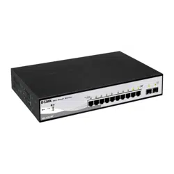
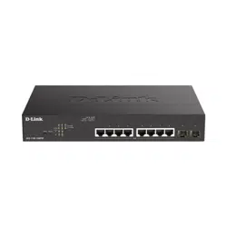
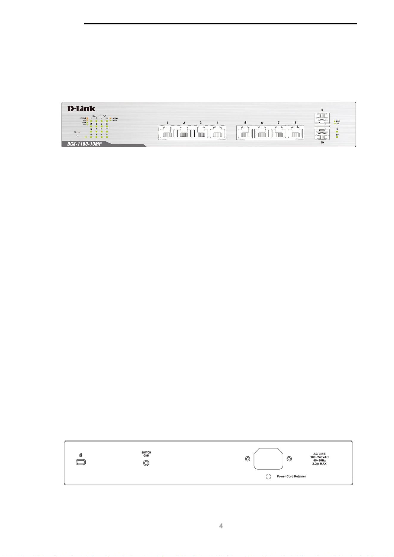
DGS-1100-10MP
8-Port 10/100/1000 Mbps + 2-Port SFP 1000 Mbps PoE switch
Front Panel
Figure 2-1
-
DGS-1100-10MP Front Panel
Power LED: The Power LED lights up when the switch is connected to a power source.
Link/Act/Speed LED (Ports 1-8):
Solid Green: When there is a secure 1000Mbps connection at the port.
Blinking Green or Amber: Indicates that the switch is either sending or receiving data to the
port.
Solid Amber: Indicates that the port is running at 10/100Mbps.
Light off: No link.
PoE Mode (Ports 1- 8):
Green: Indicates that PoE mode is active.
Amber: Indicates that there is an issue with the PoE mode activating properly.
Light off: Indicates that PoE mode is not active.
Link/Act/Speed LED (Ports 9-10):
Solid Green: There is a secure 1000Mbps connection at the port.
Blinking Green: There is reception or transmission occurring at the port.
Light off: No link.
Reset: By pressing the Reset button until the power LED turns amber, the switch will change back to
the default configuration and all changes will be lost.
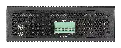
Rear Panel
Figure 2-2 – DGS-1100-10MP Rear Panel

D-Link DGS-1100 MP/MPP Series Switch User Manual
5
Power: The power port is where to connect the AC power cord.
CAUTION: The SFP ports should use UL listed Optical Transceiver product,
Rated Laser Class I. 3.3Vdc.
CAUTION: This equipment is to be connected only to PoE networks without
routing to the outside plant.
D-Link DGS-1100 MP/MPP Series Switch User Manual
6
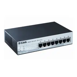
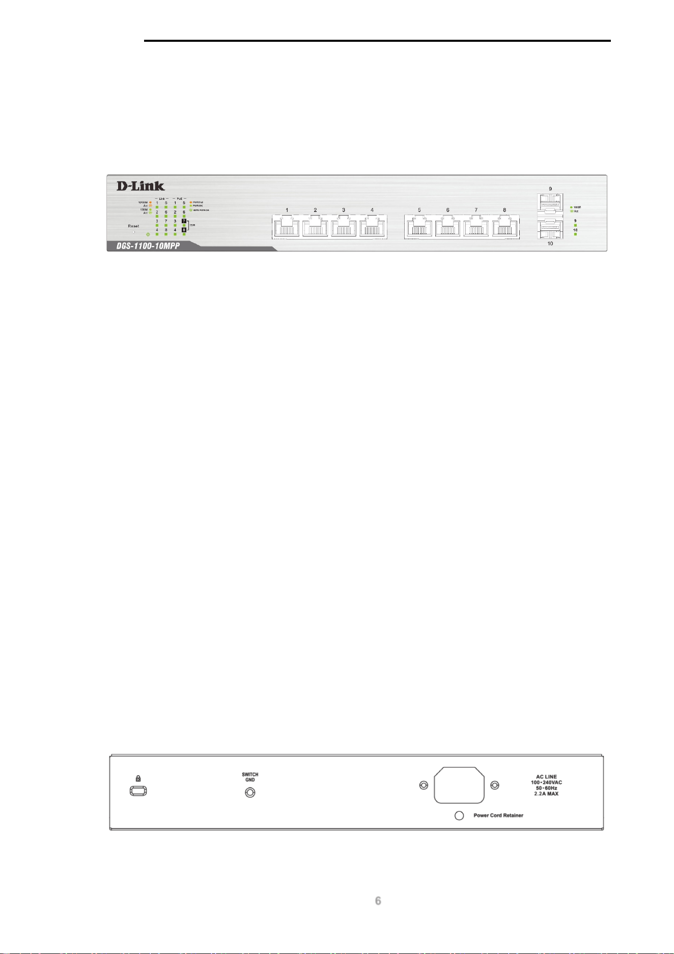
DGS-1100-10MPP
8-Port 10/100/1000 Mbps + 2-Port SFP 1000 Mbps PoE switch
Front Panel
Figure 2-3 – DGS-1100-10MPP Front Panel
Power LED: The Power LED lights up when the switch is connected to a power source.
Link/Act/Speed LED (Ports 1-8):
Solid Green: When there is a secure 1000Mbps connection at the port.
Blinking Green or Amber: Indicates that the switch is either sending or receiving data to the
port.
Solid Amber: Indicates that the port is running at 10/100Mbps.
Light off: No link.
PoE Mode (Ports 1- 8):
Green: Indicates that PoE mode is active.
Amber: Indicates that there is an issue with the PoE mode activating properly.
Light off: Indicates that PoE mode is not active.
Link/Act/Speed LED (Ports 9-10):
Solid Green: There is a secure 1000Mbps connection at the port.
Blinking Green: There is reception or transmission occurring at the port.
Light off: No link.
Reset: By pressing the Reset button until the power LED turns amber, the switch will change back to
the default configuration and all changes will be lost.
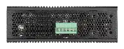
Rear Panel
Figure 2-4 – DGS-1100-10MPP Rear Panel

D-Link DGS-1100 MP/MPP Series Switch User Manual
7
Power: Connect the supplied AC power cable to this port.
CAUTION: The SFP ports should use UL listed Optical Transceiver product,
Rated Laser Class I. 3.3Vdc.
CAUTION: This equipment is to be connected only to PoE networks without
routing to the outside plant.

D-Link DGS-1100 MP/MPP Series Switch User Manual
8
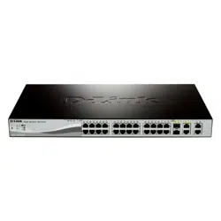
DGS-1100-26MP
24-Port 10/100/1000 Mbps + 2-Port Combo 1000BASE-T/SFP PoE switch
Front Panel
Figure 2-5 – DGS-1100-26MP Front Panel
Power LED: The Power LED lights up when the switch is connected to a power source.
Link/Act/Speed LED (Ports 1-24):
Solid Green: When there is a secure 1000Mbps connection at the port.
Blinking Green or Amber: Indicates that the switch is either sending or receiving data to the
port.
Solid Amber: Indicates that the port is running at 10/100Mbps.
Light off: No link.
PoE Mode (Ports 1- 24):
Green: Indicates that PoE mode is active.
Amber: Indicates that there is an issue with the PoE mode activating properly.
Light off: Indicates that PoE mode is not active.
Link/Act/Speed LED (Ports 25-26):
Solid Green: There is a secure 1000Mbps connection at the port.
Blinking Green: There is reception or transmission occurring at the port.
Solid Amber: Indicates that the port is running at 10/100Mbps.
Light off: No link.
LED Mode Button: Pressing this button will change the LED behavior from Link mode, and PoE
Mode.
Reset: By pressing the Reset button until the power LED turns amber, the switch will change back to
the default configuration and all changes will be lost.
NOTE: The LED behavior for ports 1- 24 will switch between Link mode and PoE
mode when the PoE mode is active.
D-Link DGS-1100 MP/MPP Series Switch User Manual
9
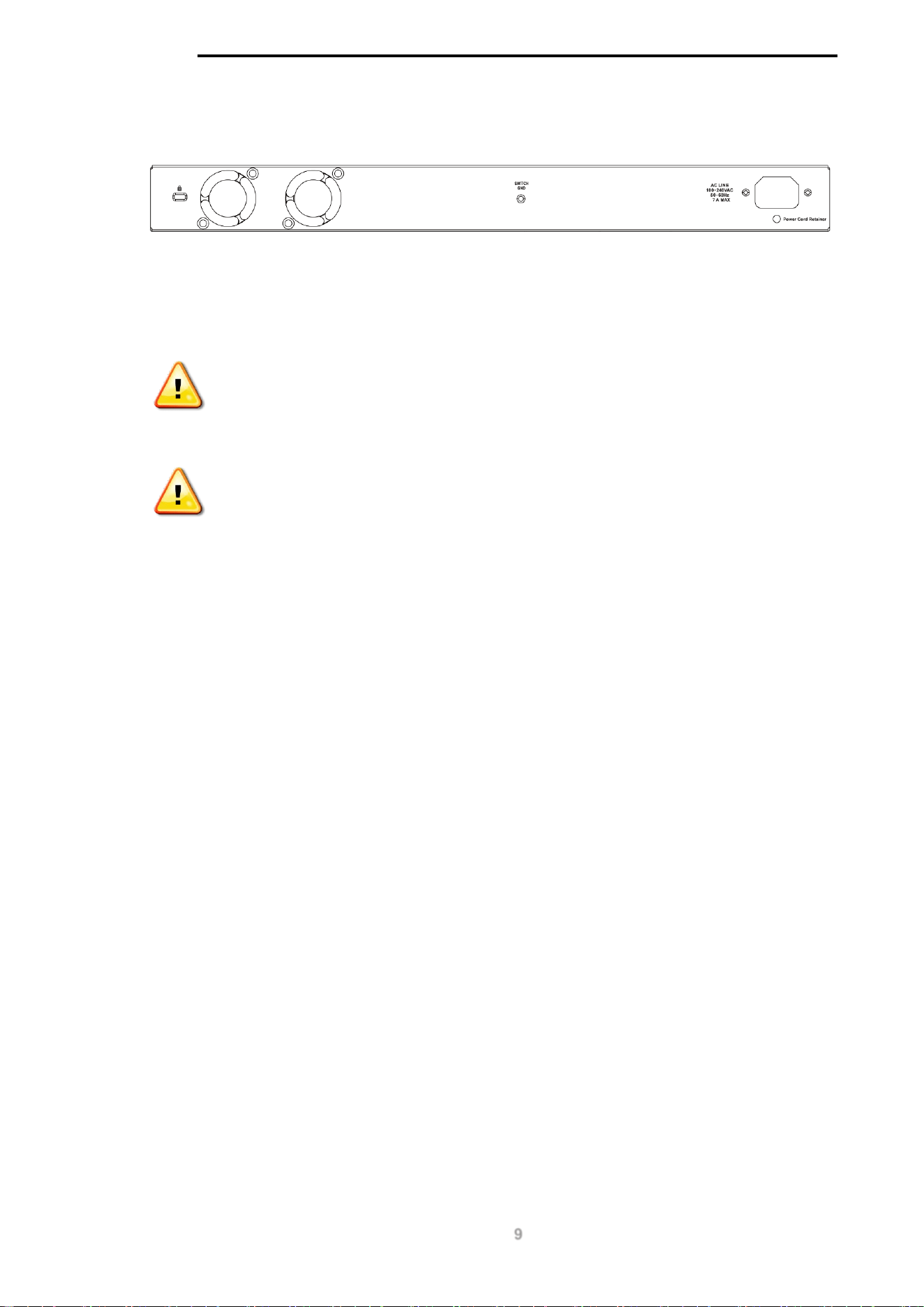
Rear Panel
Figure 2-6 – DGS-1100-26MP Rear Panel
Power: Connect the supplied AC power cable to this port.
CAUTION: The SFP ports should use UL listed Optical Transceiver product,
Rated Laser Class I. 3.3Vdc.
CAUTION: This equipment is to be connected only to PoE networks without
routing to the outside plant.
D-Link DGS-1100 MP/MPP Series Switch User Manual
10
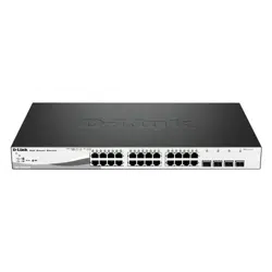
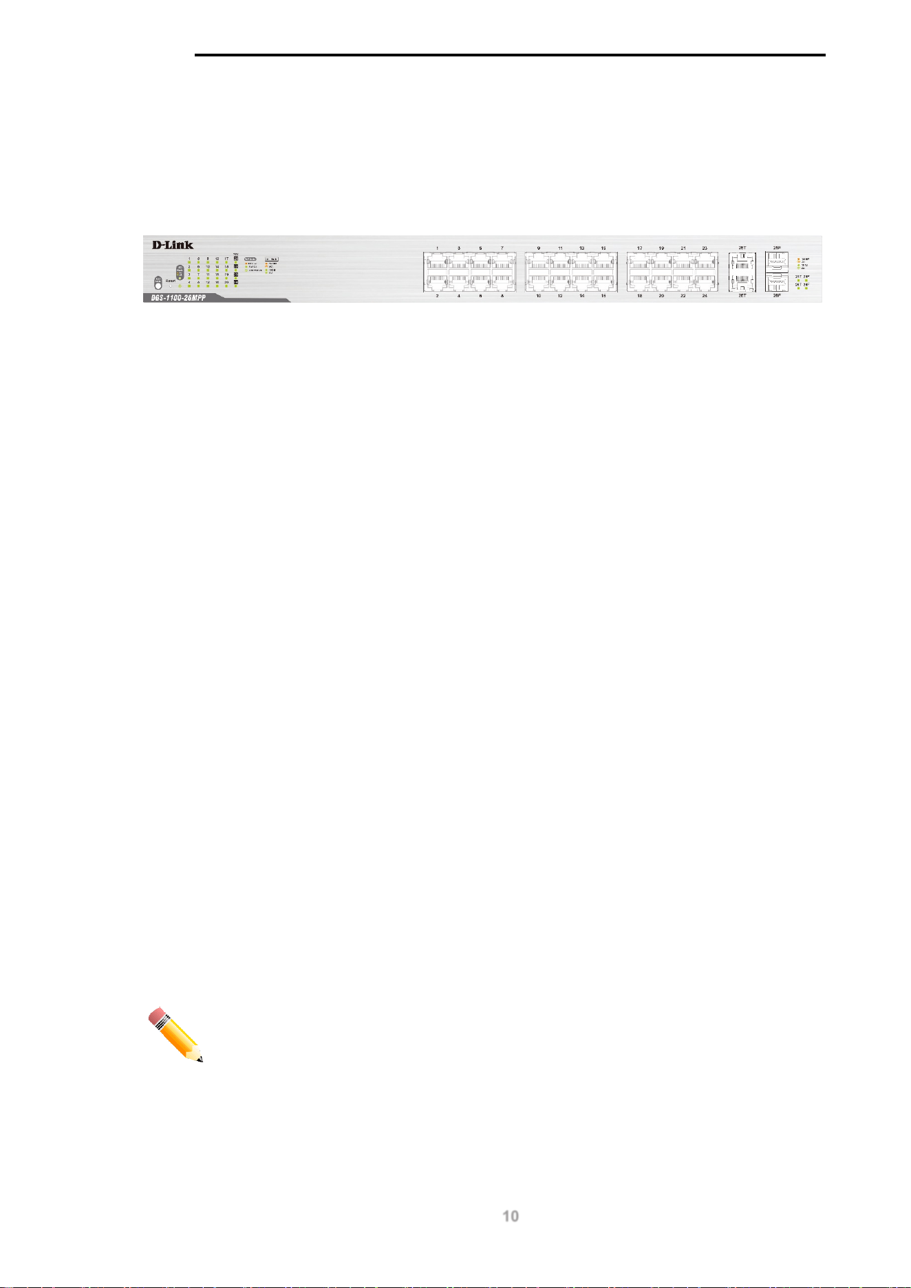
DGS-1100-26MPP
24-Port 10/100/1000 Mbps + 2-Port Combo 1000BASE-T/SFP PoE switch
Front Panel
Figure 2-7 – DGS-1100-26MPP Front Panel
Power LED: The Power LED lights up when the switch is connected to a power source.
Link/Act/Speed LED (Ports 1-24):
Solid Green: When there is a secure 1000Mbps connection at the port.
Blinking Green or Amber: Indicates that the switch is either sending or receiving data to the
port.
Solid Amber: Indicates that the port is running at 10/100Mbps.
Light off: No link.
PoE Mode (Ports 1- 24):
Green: Indicates that PoE mode is active.
Amber: Indicates that there is an issue with the PoE mode activating properly.
Light off: Indicates that PoE mode is not active.
Link/Act/Speed LED (Ports 25-26):
Solid Green: There is a secure 1000Mbps connection at the port.
Blinking Green: There is reception or transmission occurring at the port.
Solid Amber: Indicates that the port is running at 10/100Mbps.
Light off: No link.
LED Mode Button: Pressing this button will change the LED behavior from Link mode, and PoE
Mode.
Reset: By pressing the Reset button until the power LED turns amber, the switch will change back to
the default configuration and all changes will be lost.
NOTE: The LED behavior for ports 1- 24 will switch between Link mode and PoE
mode when the PoE mode is active.

D-Link DGS-1100 MP/MPP Series Switch User Manual
11
Rear Panel
Figure 2-8 – DGS-1100-26MPP Rear Panel
Power: Connect the supplied AC power cable to this port.
CAUTION: The SFP ports should use UL listed Optical Transceiver product,
Rated Laser Class I. 3.3Vdc.
CAUTION: This equipment is to be connected only to PoE networks without
routing to the outside plant.
D-Link DGS-1100 MP/MPP Series Switch User Manual
12
3. Hardware Installation
This chapter provides unpacking and installation information for the D-Link switch.
Step 1: Unpacking
Open the shipping carton and carefully unpack its contents. Please consult the packing list located
below to make sure all items are present and undamaged. If any item is missing or damaged, please
contact your local D-Link reseller for a replacement.
Packing Contents
• One D-Link DGS-1100 MP/MPP Series switch
• One AC power cord
• Four rubber feet
• Screws and two mounting brackets
• One accessory kit for a ground screw
• One Multi-lingual Getting Started Guide
• One CD with User Manual
Step 2: Switch Installation
For safe switch installation and operation, it is recommended that you:
• Visually inspect the power cord to see that it is secured fully to the AC power connector.
• Make sure that there is proper heat dissipation and adequate ventilation around the switch.
• Do not place heavy objects on the switch.
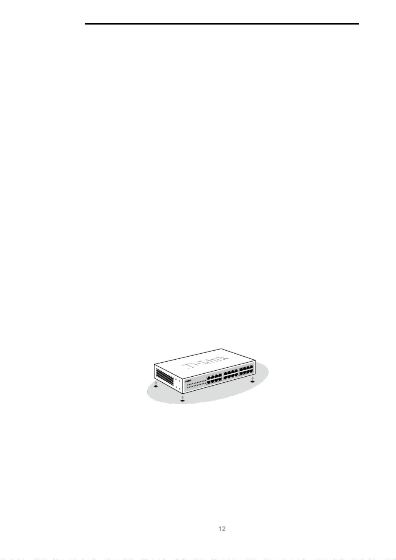
Desktop or Shelf Installation
When installing the switch on a desktop or shelf, the rubber feet included with the device must be
attached on the bottom at each corner of the device’s base. Allow enough ventilation space between
the device and the objects around it.
Figure 3-1 – Attach the adhesive rubber pads to the bottom
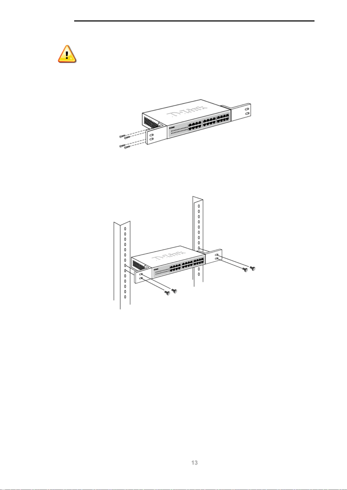
Rack Installation
The switch can be mounted in an EIA standard size 19-inch rack, which can be placed in a wiring
closet with other equipment.
D-Link DGS-1100 MP/MPP Series Switch User Manual
13
CAUTION: Ensure the power cable is disconnected before installing the switch.
To install, attach the mounting brackets to the switch’s side panels (one on each side) and secure
them with the screws provided.
Figure 3-2 – Attach the mounting brackets to the switch
Then, use the screws provided with the equipment rack to mount the switch in the rack.
Figure 3-3 – Mount the switch in the rack or chassis
Please be aware of following safety Instructions when installing:
A) Elevated Operating Ambient - If installed in a closed or multi-unit rack assembly, the operating
ambient temperature of the rack environment may be greater than room ambient. Therefore,
consideration should be given to installing the equipment in an environment compatible with the
maximum ambient temperature (Tma) specified by the manufacturer.
B) Reduced Air Flow - Installation of the equipment in a rack should be such that the amount of air
flow required for safe operation of the equipment is not compromised.
C) Mechanical Loading - Mounting of the equipment in the rack should be such that a hazardous
condition is not achieved due to uneven mechanical loading.
D) Circuit Overloading - Consideration should be given to the connection of the equipment to the
supply circuit and the effect that overloading of the circuits might have on overcurrent protection and
supply wiring. Appropriate consideration of equipment nameplate ratings should be used when
addressing this concern.
D-Link DGS-1100 MP/MPP Series Switch User Manual
14
E) Reliable Earthing - Reliable earthing of rack-mounted equipment should be maintained. Particular
attention should be given to supply connections other than direct connections to the branch circuit
(e.g. use of power strips)."
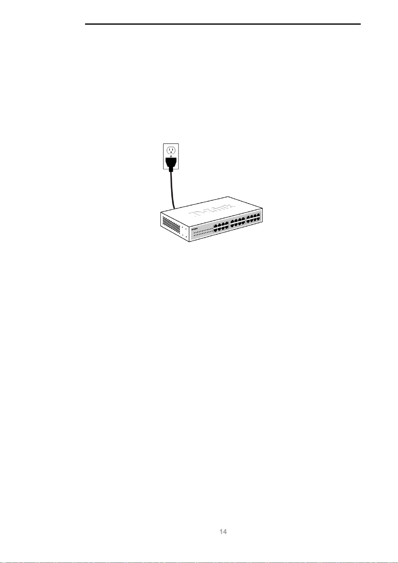
Step 3: Plugging in the AC Power Cord
Users may now connect the AC power cord into the rear of the switch and to an electrical outlet
(preferably one that is grounded and surge protected).
Figure 3-4 – Plugging the switch into an outlet
Power Failure
As a precaution, the switch should be unplugged in case of power failure. When power is resumed,
the switch should be plugged back in.
Grounding the Switch
This section describes how to connect the DGS-1100 MP/MPP Series switch to ground. You must
complete this procedure before powering your switch.
Required Tools and Equipment
• Ground screws (included in the accessory kit): One M4 x 6 mm (metric) pan-head screw
• Ground cable (not included in the accessory kit): The grounding cable should be sized
according to local and national installation requirements. Depending on the power supply
and system, a 12 to 6 AWG copper conductor is required for U.S installation. Commercially
available 6 AWG wire is recommended. The length of the cable depends on the proximity of
the switch to proper grounding facilities.
• A screwdriver (not included in the accessory kit)
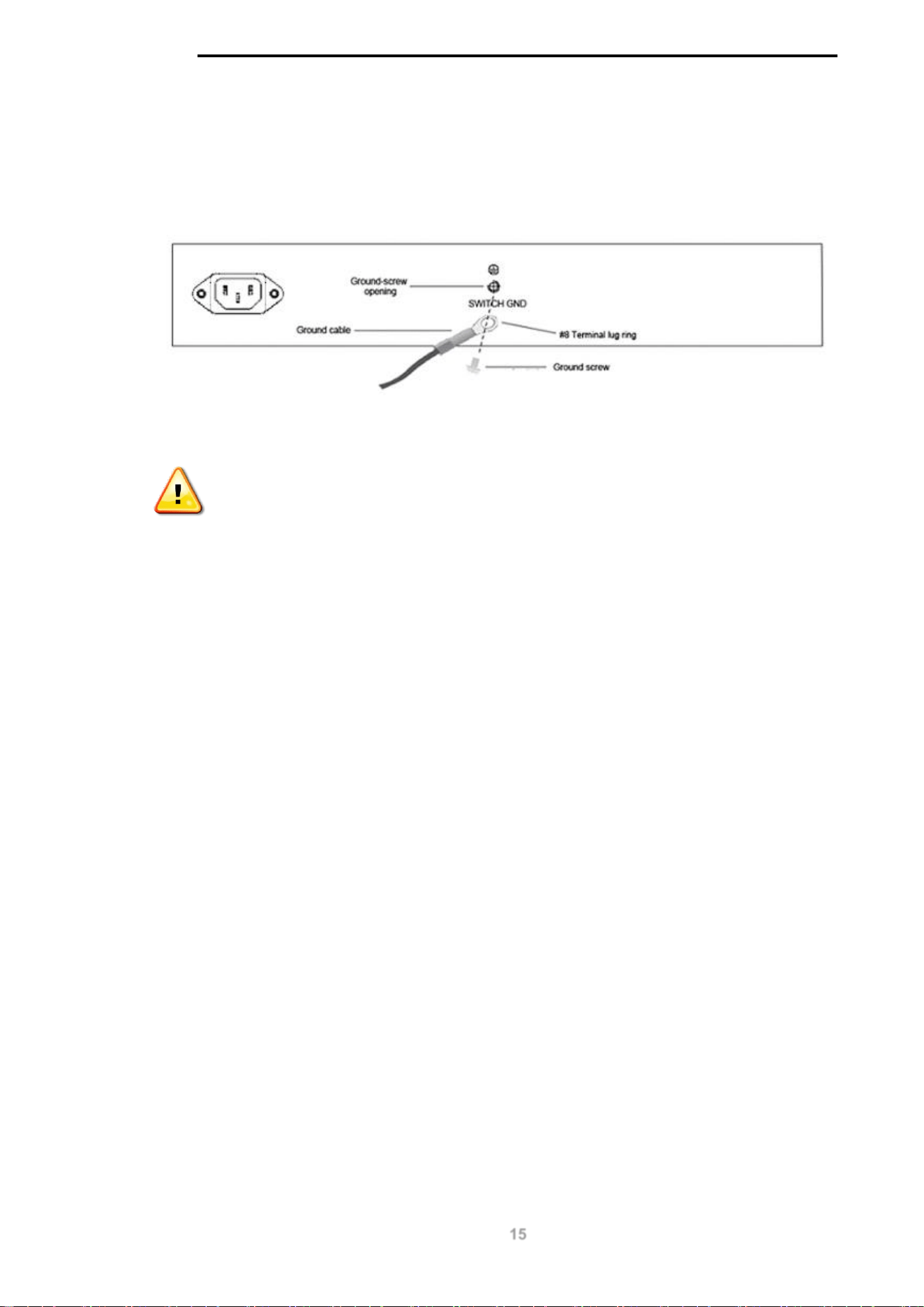
Follow these steps to ground the switch:
Step 1: Verify that the switch is not connected to a power supply.
Step 2: Use the ground cable to place the #8 terminal lug ring on top of the ground-screw opening,
as seen in the figure below.
Step 3: Insert the ground screw into the ground-screw opening.
Step 4: Using a screwdriver, tighten the ground screw to secure the ground cable to the switch.
D-Link DGS-1100 MP/MPP Series Switch User Manual
15
Step 5: Attach the terminal lug ring at the other end of the grounding cable to an appropriate
grounding stud or bolt on rack where the switch is installed.
Step 6: Verify if the connections at the ground connector on the switch and the rack are securely
attached.
Figure 3-5 – Ground cable, screw and #8 terminal lug rings
CAUTION: This equipment is to be connected only to PoE networks without
routing to the outside plant.

D-Link DGS-1100 MP/MPP Series Switch User Manual
16
4. Web-based Switch Configuration
Management Options
Connecting using the Web User Interface
Logging onto the
Smart Wizard
Web User Interface
Management Options
The switch provides multiple access platforms that can be used to configure, manage and monitor
networking features available on the switch. Currently there are three management platforms
available and they are described below.
Web-based Management Interface
After successfully installing the switch, the user can configure the switch, monitor the LED panel, and
display statistics graphically using a Web browser, such as Microsoft® Internet Explorer, Opera
Firefox, Safari, or Google Chrome.
SNMP-based Management
The switch can be managed with an SNMP-compatible console program. The switch supports
SNMP version 1.0, and version 2c. The SNMP agent decodes the incoming SNMP messages and
responds to requests with MIB objects stored in the database. The SNMP agent updates the MIB
objects to generate statistics and counters.
D-Link Network Assistant
DNA (D-Link Network Assistant) included on the installation CD is a program for discovering DGS-
1100 MP/MPP Series switches with the same L2 network segment connected to your PC. This tool
can support windows 2000, XP, Vista, and Windows 7.
Connecting using the Web User Interface
Most software functions of the DGS-1100 MP/MPP Series switches can be managed, configured
and monitored via the embedded web-based (HTML) interface. Manage the switch from remote
stations anywhere on the network through a standard web browser. The web browser acts as a
universal access tool and can communicate directly with the switch using the HTTP or HTTPS
protocol.
You need the following equipment to begin the web configuration of your device:
• A PC with a RJ-45 Ethernet connection
• A standard Ethernet cable
Figure 4-1 – Connecting to a DGS-1100 MP/MPP Series switch

D-Link DGS-1100 MP/MPP Series Switch User Manual
17
Connect the Ethernet cable to any of the ports on the front panel of the switch and to the Ethernet
port on the PC.
Logging onto the Web User Interface
To access the Web UI, simply open a web browser and enter the switch’s default IP address into the
address bar. Make sure that the IP address of the management PC is in the same subnet as the IP
address of the switch you are trying to connect to.
NOTE: The default IP address of the switch is 10.90.90.90, with a subnet mask
of 255.0.0.0.
NOTE: The default username is ‘admin’ and password is ‘admin’.
After successfully connecting to the Web UI, the Smart Wizard will be launched.
D-Link DGS-1100 MP/MPP Series Switch User Manual
18
Smart Wizard
The Smart Wizard is a configuration utility that is launched the first time the Web UI is accessed. It
allows users to configure basic settings such as the switch mode, management IP and password. It
can also be used to switch between Standard Mode and Surveillance Mode Web UI types.
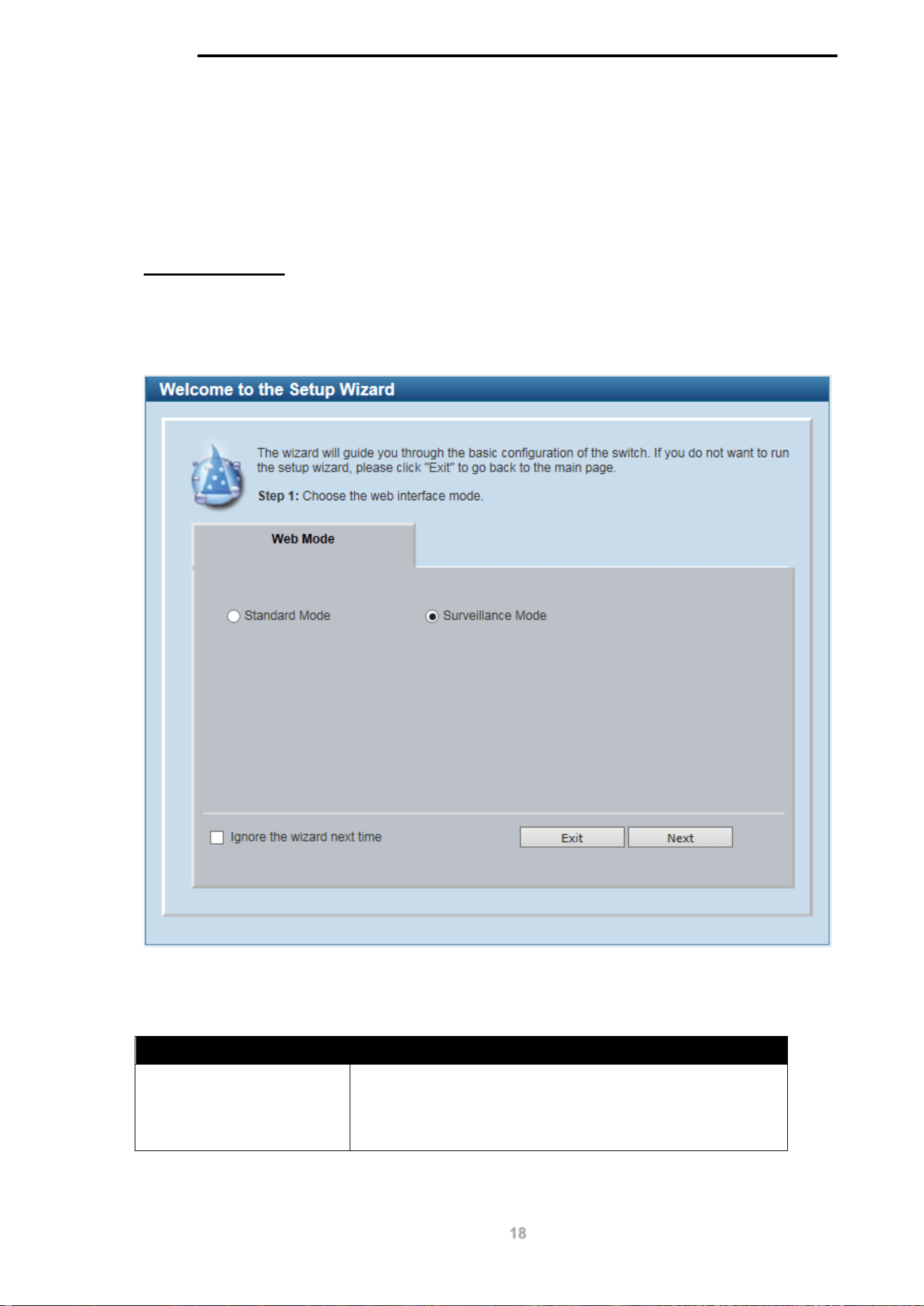
Step 1 – Web Mode
The initial page allows the user to choose between Standard Mode and Surveillance Mode on the
switch. This can be changed at any time by returning to the Smart Wizard.
For more information on the Standard Mode features of the switch, please refer to the Standard
Mode Web UI Reference Guide.
Figure 4-2 Web Mode window
The fields that can be configured are described below:
Parameter Description
Web Mode Select the Surveillance Mode option to continue the Smart
Wizard in Surveillance Mode.
Please refer to the Standard Mode Web UI Reference Guide
for more information on Standard Mode.
Tick the Ignore the wizard next time option to skip the Smart Wizard on the next login.
D-Link DGS-1100 MP/MPP Series Switch User Manual
19
Click the Exit button to discard the changes made, exit the Smart Wizard, and continue to the
Standard Mode Web UI.
Click the Next button to accept the changes made and continue to the next step.
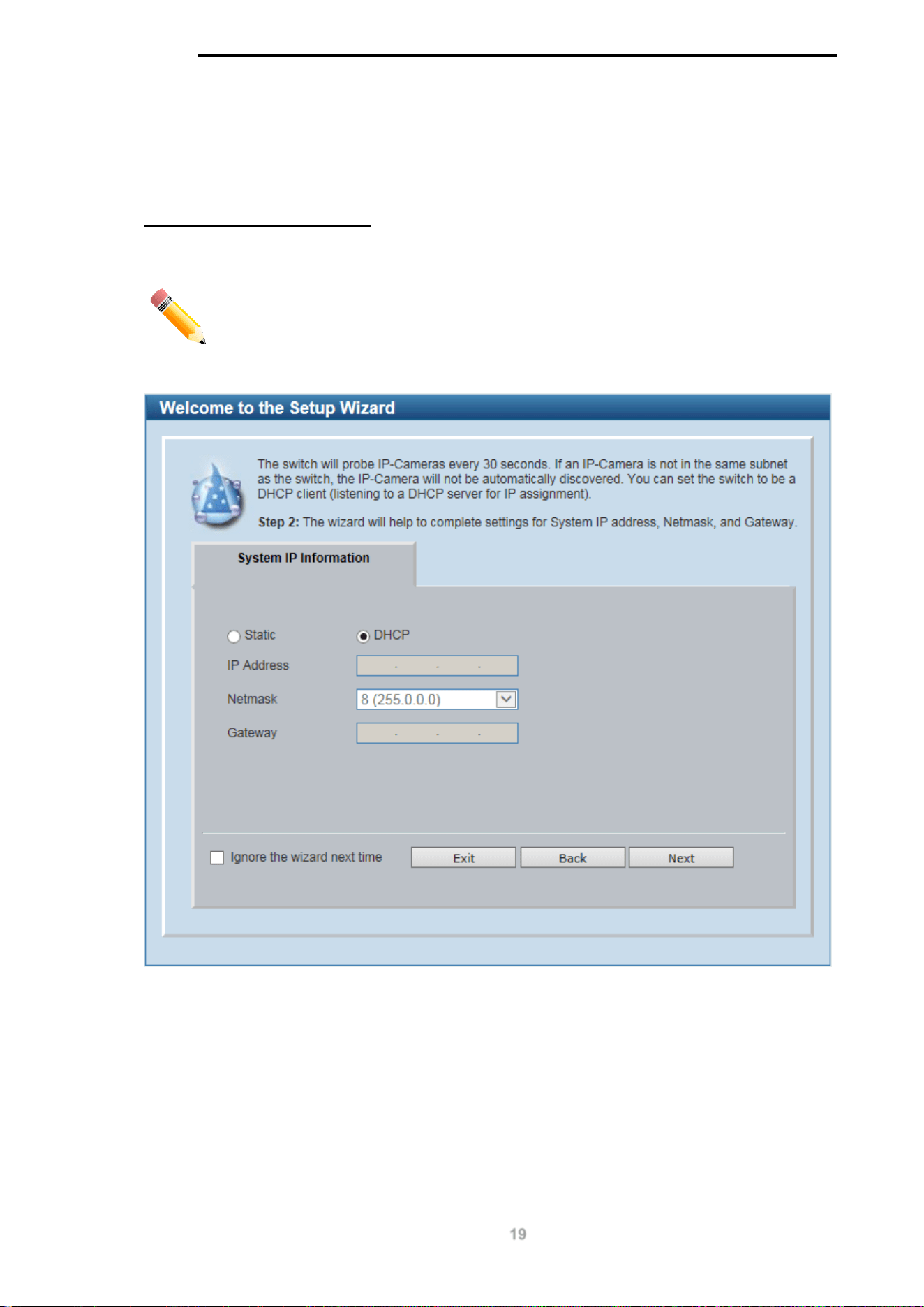
Step 2 – System IP Information
In this window, the user can configure the IP address assignment method, the static IP address,
netmask and gateway address.
NOTE: The switch will probe IP-Cameras every 30 seconds. If an IP-Camera is
not in the same subnet as the switch, the IP-Camera will not be automatically
discovered. Place the switch management IP in the same subnet as the IP-
Cameras for the cameras to be automatically added to the Surveillance Mode
Web UI.
Figure 4-3 System IP Information window
D-Link DGS-1100 MP/MPP Series Switch User Manual
20
The fields that can be configured are described below:
Parameter Description
Static
Select this option to manually configure and use IP address
settings on this switch.
DHCP
Select this option to obtain IP address settings from a DHCP
server.
IP Address
Enter the IP address of the switch here.
Netmask
Select the netmask option here.
Gateway
Enter the default gateway IP address here.
Tick the Ignore the wizard next time option to skip the Smart Wizard on the next login.
Click the Exit button to discard the changes made, exit the Smart Wizard, and continue to the
Standard Mode Web UI.
Click the Next button to accept the changes made and continue to the next step.
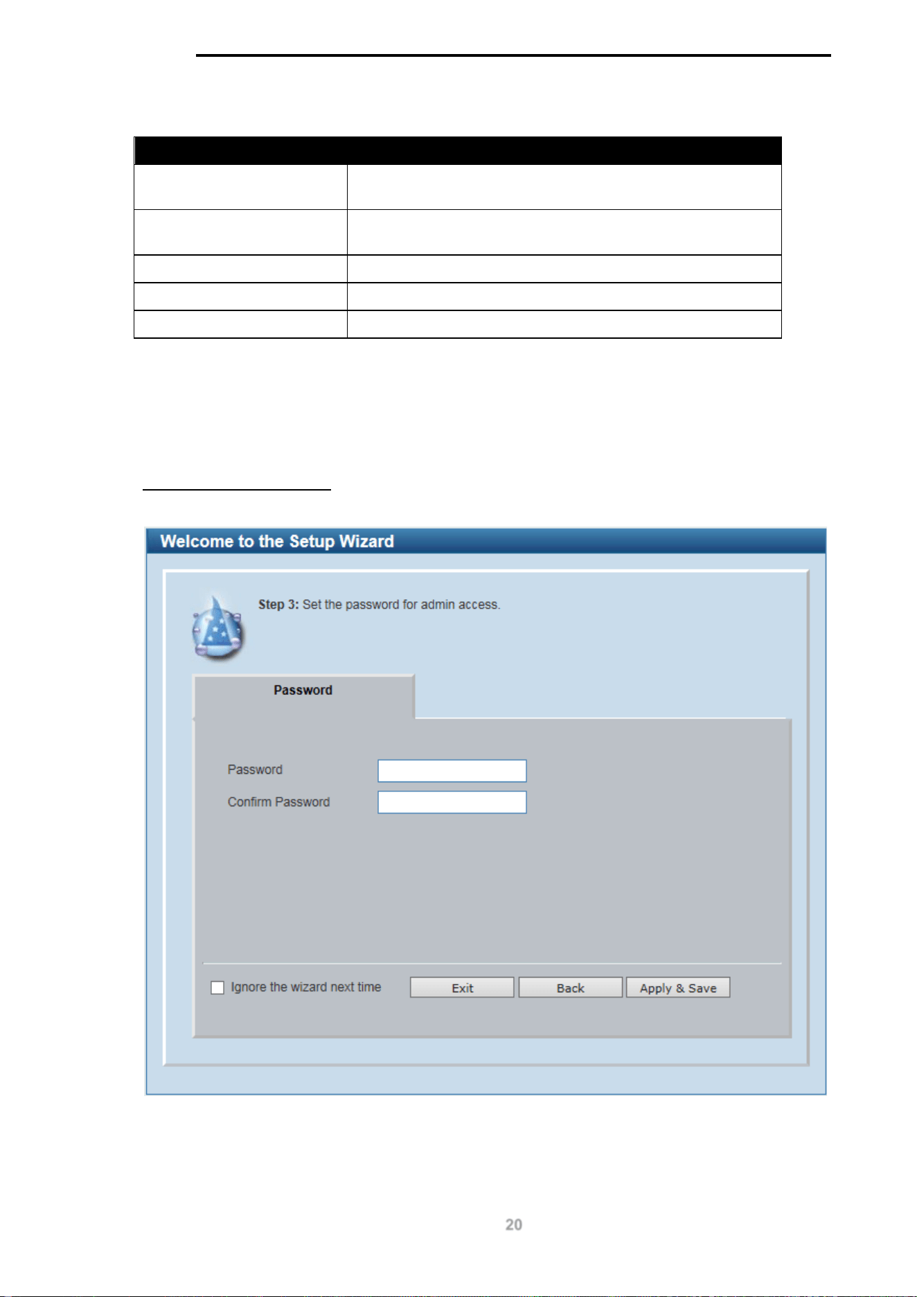
Step 3 – Admin Password
In this window, the user can set the password used with the admin account.
Figure 4-4 Admin Password window
Tick the Ignore the wizard next time option to skip the Smart Wizard on the next login.

D-Link DGS-1100 MP/MPP Series Switch User Manual
21
Click the Exit button to discard the changes made, exit the Smart Wizard, and continue to the
Standard Mode Web UI.
Click the Apply & Save button to accept the changes made, and then continue to the Web UI.
NOTE:
Standard Mode and Surveillance Mode Web UIs share the same
configuration files. Any features enabled in one interface will be made available
in the other interface, for example: PoE scheduling, SNMP settings and the
surveillance VLAN in use.
NOTE:
Settings are saved between interface types. It is possible to switch
interface types and re-run the Smart Wizard without losing settings saved in one
version of the interface.
D-Link DGS-1100 MP/MPP Series Switch User Manual
22
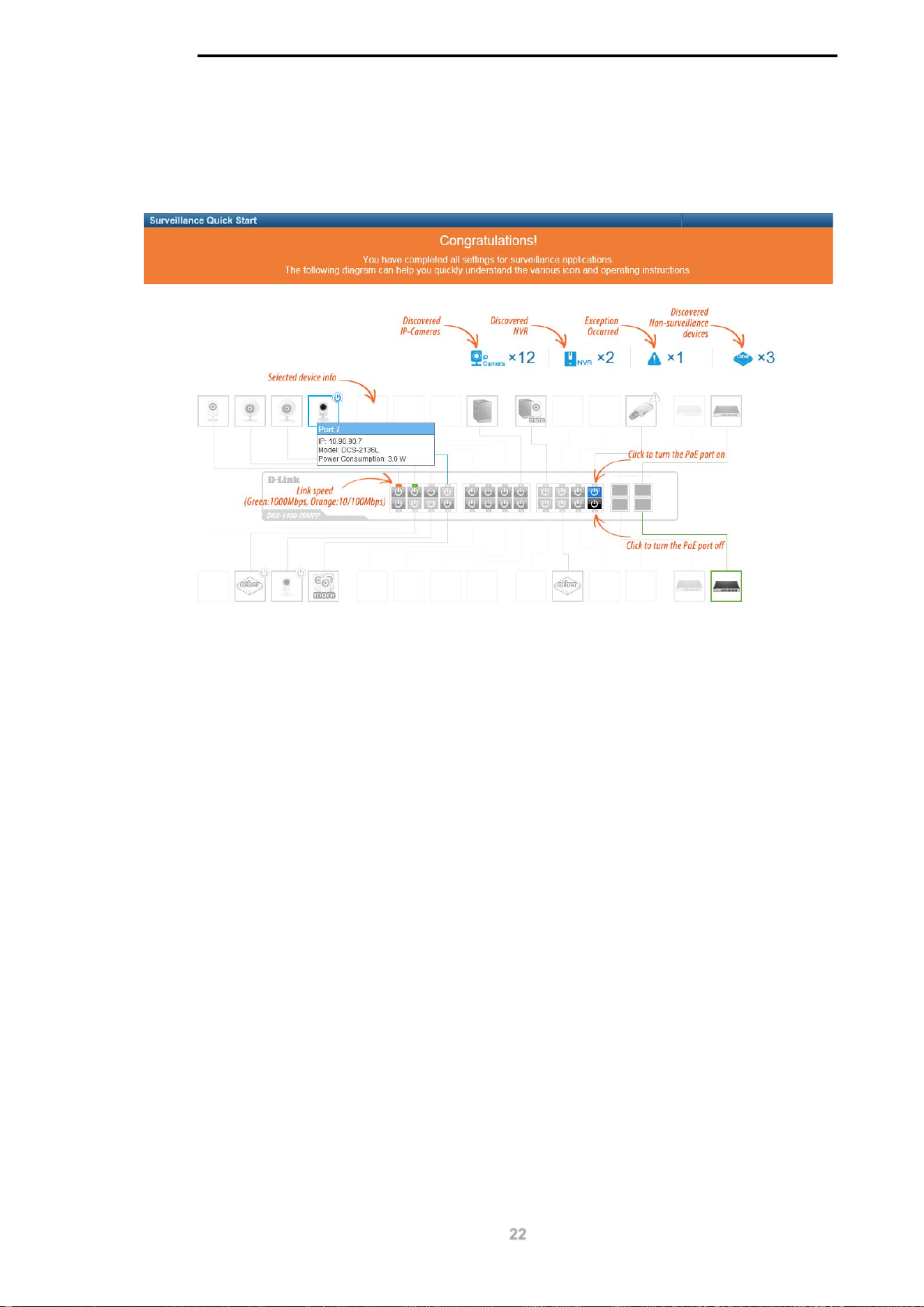
Web User Interface
When you complete the Surveillance Mode Smart Wizard you will be presented with the following
screen:
Figure 4-5 Congratulations window
Scroll to the bottom of the page and click the OK button to continue to the Web UI.
D-Link DGS-1100 MP/MPP Series Switch User Manual
23
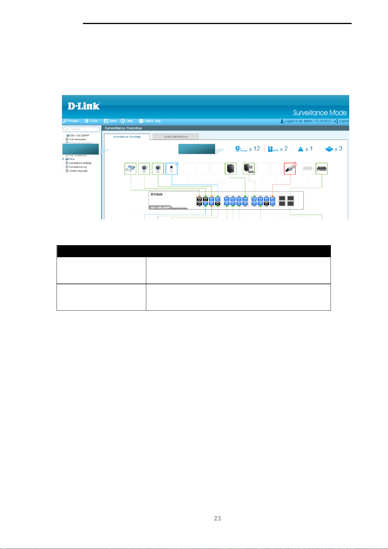
Areas of the User Interface
The figure below shows the user interface. Two distinct areas divide the user interface, as described
in the table.
Figure 4-6 Main Web UI Window
Area Number Description
AREA 1
The navigation menu is displayed in this area. Click on the
links and navigate the folder structure to display information
on the main page.
AREA 2
This is the main page for displaying information and
configuration options for the switch. The page displayed here
is based on the selection in AREA 1.
AREA 1
AREA 2
D-Link DGS-1100 MP/MPP Series Switch User Manual
24
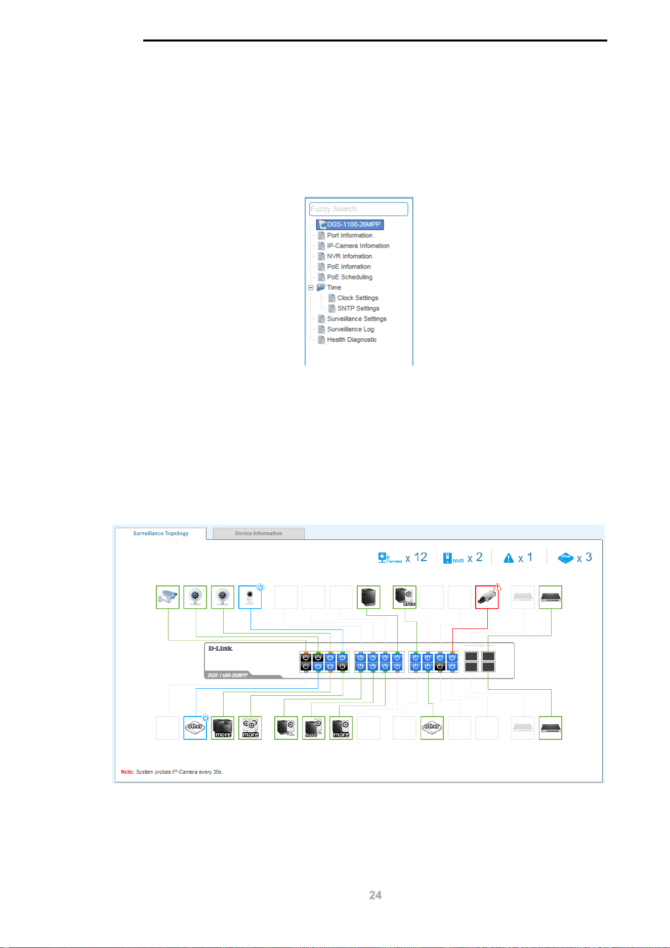
5. Surveillance Overview
This loads automatically when you log-in to the switch and contains two tabs; Surveillance
Topology and Device Information. To return to the Surveillance Overview page after viewing other
pages, click the model number of the switch at the top of the navigation menu.
Figure 5-1 Switch Model Number
Surveillance Topology
This is the default tab on the Surveillance Overview page. It contains a diagram of the surveillance
topology, including an overview of the devices connected to the switch.
To view the following window, click on the model number of the switch at the top of the navigation
menu:
Figure 5-2 Surveillance Topology Window
There is a device count at the top of the page, listing the number of connected IP-Cameras,
Network Video Recorders (NVRs) and unrecognized devices. It also lists the number of warnings
on the system.
D-Link DGS-1100 MP/MPP Series Switch User Manual
25
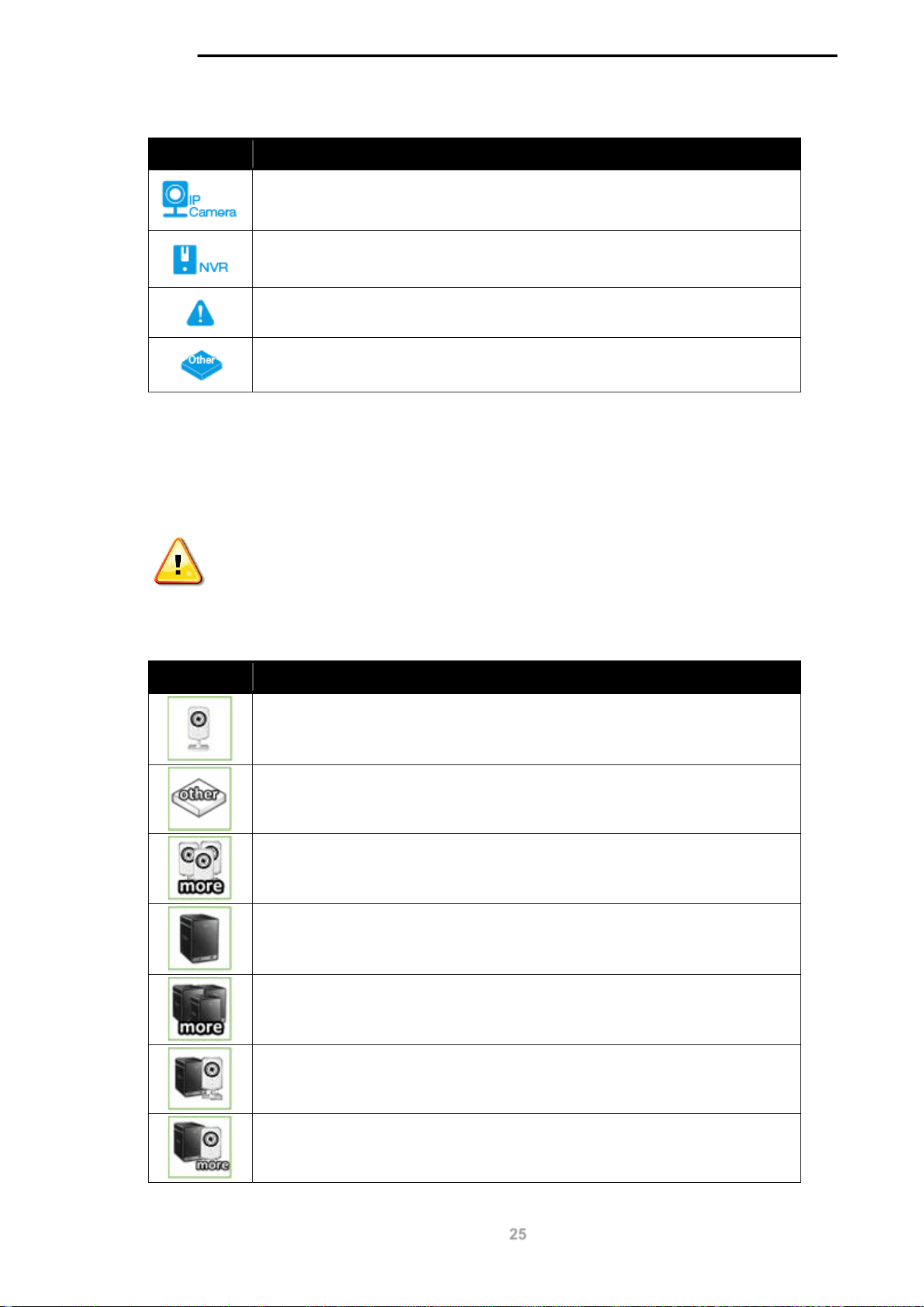
The icon descriptions are as follows:
Icon Description
The total number of IP-Cameras detected.
The total number of NVRs detected.
The number of warnings on the system. Consult the Surveillance Log and
Health Diagnostic pages for more information.
The number of ports that have an unknown device connected that does not
support ONVIF.
The Surveillance Topology gives you more information about what is connected to each port.
Hover over each device icon to get more information about the recognized devices, such as: the
number of devices, device type, IP address, power consumption, link speed and errors. Click on
the ‘more’ link to get more information about the devices connected to a port. Each port can also
be powered-on and off using PoE by clicking the power symbol on each port.
CAUTION: Before connecting the Powered Device (PD) and enabling 60/70 W
PoE, make sure it supports IEEE 802.3bt, as otherwise it will become damaged.
See below for more information on enabling and disabling PoE.
A breakdown of each device icon is below:
Icon Description
One ONVIF IP-Camera discovered on this port.
The link is up but no ONVIF IP-Camera or NVR has been discovered on this
port.
Multiple ONVIF IP-Cameras discovered on this port.
One NVR discovered on this port. Any device fetching surveillance stream
from IP-Camera will be recognized as NVR.
Multiple NVRs discovered on this port.
One ONVIF IP-Camera and one NVR discovered on this port.
Multiple ONVIF IP-Cameras and one NVR discovered on this port.
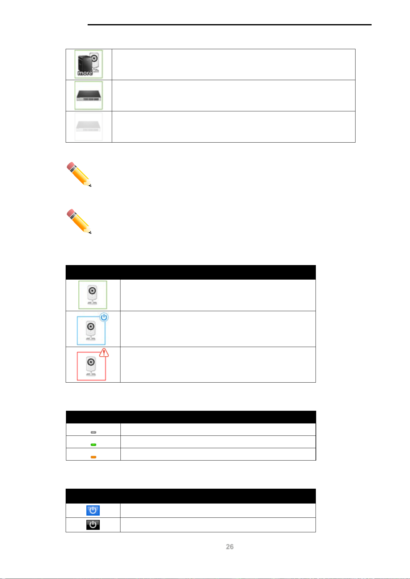
D-Link DGS-1100 MP/MPP Series Switch User Manual
26
One ONVIF IP-Camera and multiple NVRs discovered on this port.
This port is set as uplink port and it is link up.
This port is set as uplink port and it is link down.
NOTE: A breakdown of the device icons can be found by clicking the Help menu
at the top of the page.
NOTE: The system probes for new IP-Cameras every 30 seconds.
The icon border indicates the PoE status for the port:
Icon Border Description
The device is operational but not powered by PoE.
The device is operational and is powered by PoE.
The device has malfunctioned and there is a problem with
the port or device.
The port status indicators dictate the speed and status of the link:
Port Status Description
The link is down.
The port is connected at 1 Gbps.
The port is connected at 10/100 Mbps.
The PoE status is indicated by the power icon on each port:
Port Status Description
PoE is enabled on the port.
PoE is disabled on the port.
D-Link DGS-1100 MP/MPP Series Switch User Manual
27
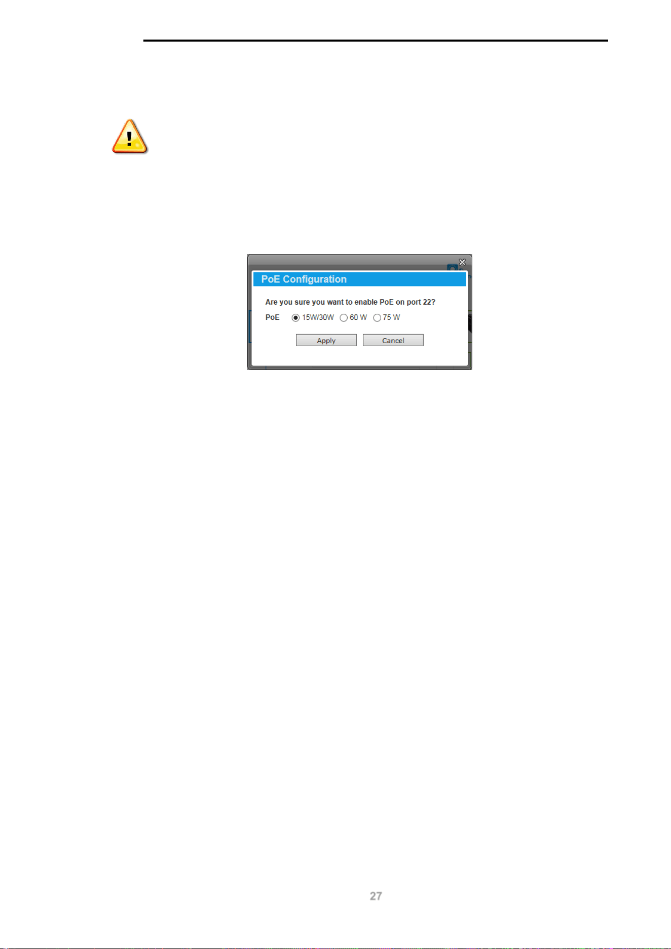
Enabling and Disabling PoE
CAUTION: Before connecting the Powered Device (PD) and enabling 60/70 W
PoE, make sure it supports IEEE 802.3bt, as otherwise it will become damaged.
The power status of each port can be changed by clicking the power icon on each port. The default
setting for PoE is on. To change the PoE type, first disable PoE and then re-enable it using the
type of PoE required.
The following dialogue box will be displayed when enabling PoE on a port:
Figure 5-3 PoE Configuration
Choose the type of PoE required. This can be either 15/30 W (60 W or 75 W is for MPP Series
only).
Click the Apply button to accept the changes made.
D-Link DGS-1100 MP/MPP Series Switch User Manual
28
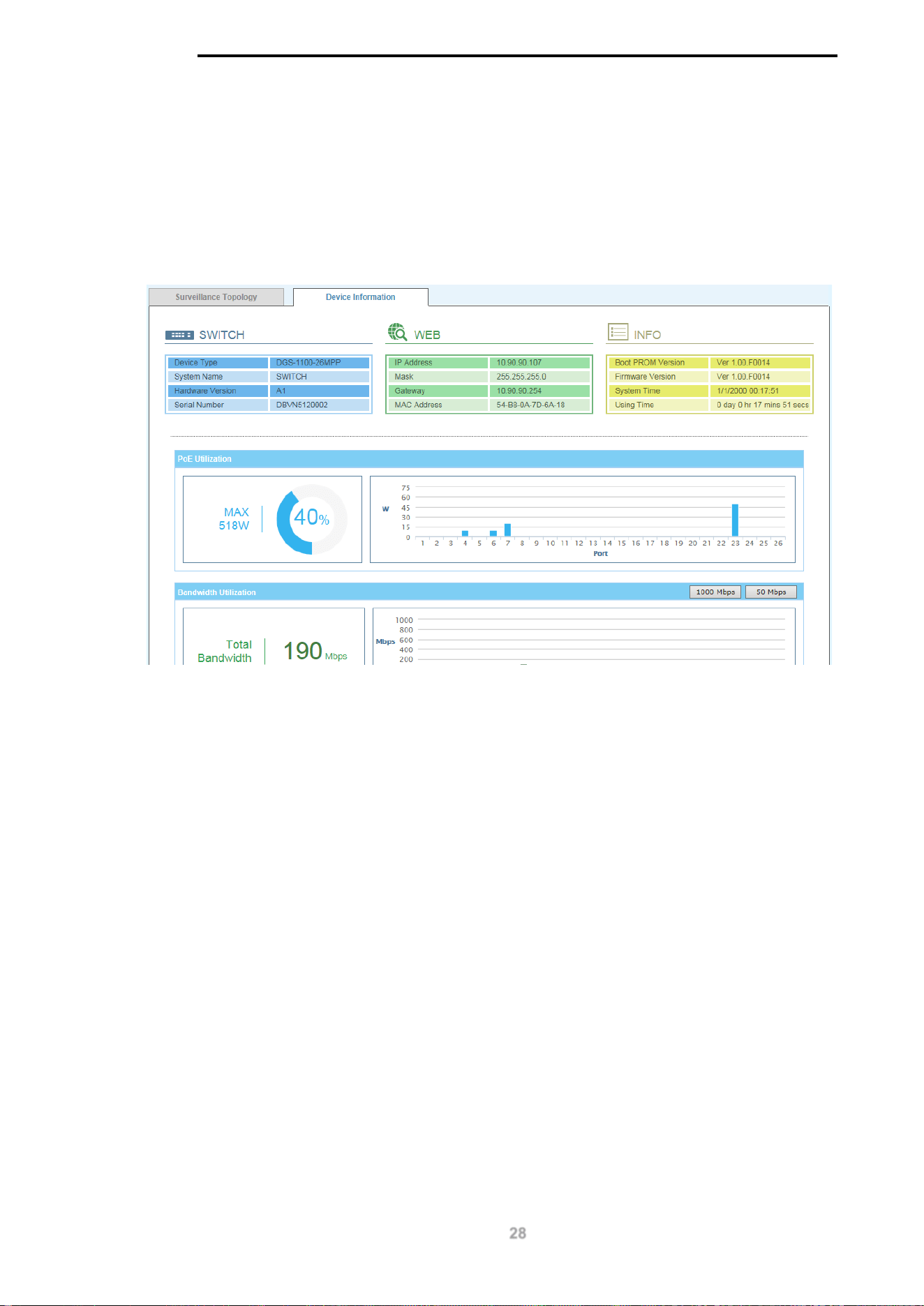
Device Information
This is the second tab on the Surveillance Overview page and is divided into 3 areas; a device
information section, PoE utilization section and bandwidth usage section.
To view the following window, click on the model number of the switch at the top of the navigation
menu and the click the Device Information tab:
Figure 5-4 Device Information Window
The device information section is sub-divided into 3 sections; switch information, web information
and system information. It contains information such as the device type, system name, serial number,
IP address settings, MAC address settings, firmware versions and system uptime.
The PoE utilization area contains PoE utilization statistics for the switch. On the left is the total PoE
utilization, with the total power budget and overall utilization shown. On the right is a per-port usage
graph, showing the PoE utilization for each individual port.
The bandwidth usage section contains bandwidth utilization for the switch. On the left the total
bandwidth shows the total inbound traffic on all ports. There is also a per-port bandwidth utilization
graph on the right, showing the inbound traffic for each individual port. The scale of the graph can be
changed by pressing the 1000 Mbps and 50 Mbps buttons above the graph.
D-Link DGS-1100 MP/MPP Series Switch User Manual
29
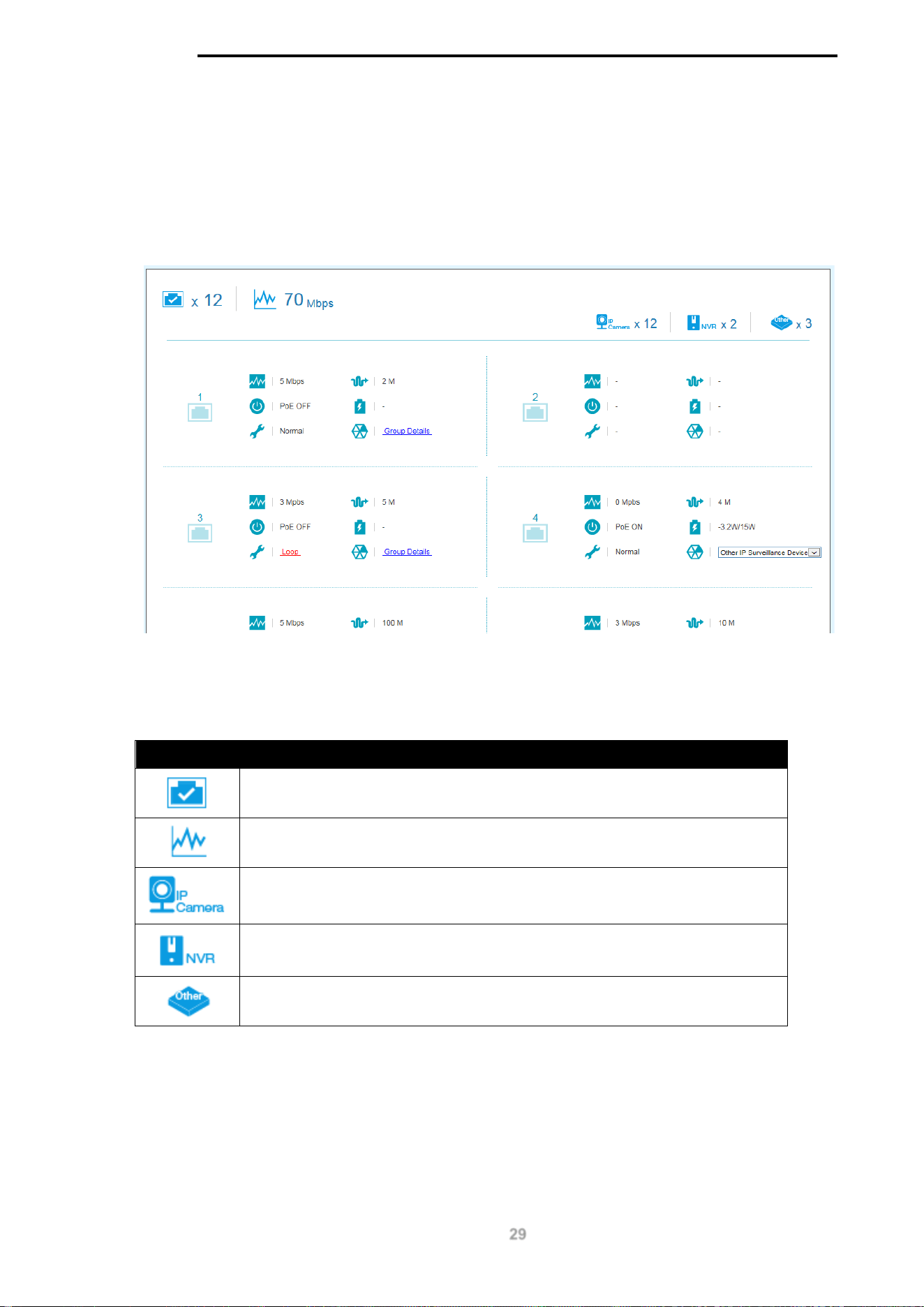
6. Port Information
The Port Information section provides an overview of the port status for each port. This includes the
throughput, PoE status, Loopback Detection Status, cable length, power consumption and the
devices connected to each port.
To view the following window, click on the Port Information link in the navigation menu:
Figure 6-1 Port Information Window
A breakdown of the devices connected, the number of ports in use and the total throughput is listed
at the top of the page. The icon descriptions are as follows:
Icon Description
The total amount of ports that are currently active.
The total inbound throughput for all ports on the switch.
The total number of ONVIF IP-Cameras detected.
The total number of NVRs detected.
The number of ports that have an unknown device connected that does not
support ONVIF.
D-Link DGS-1100 MP/MPP Series Switch User Manual
30
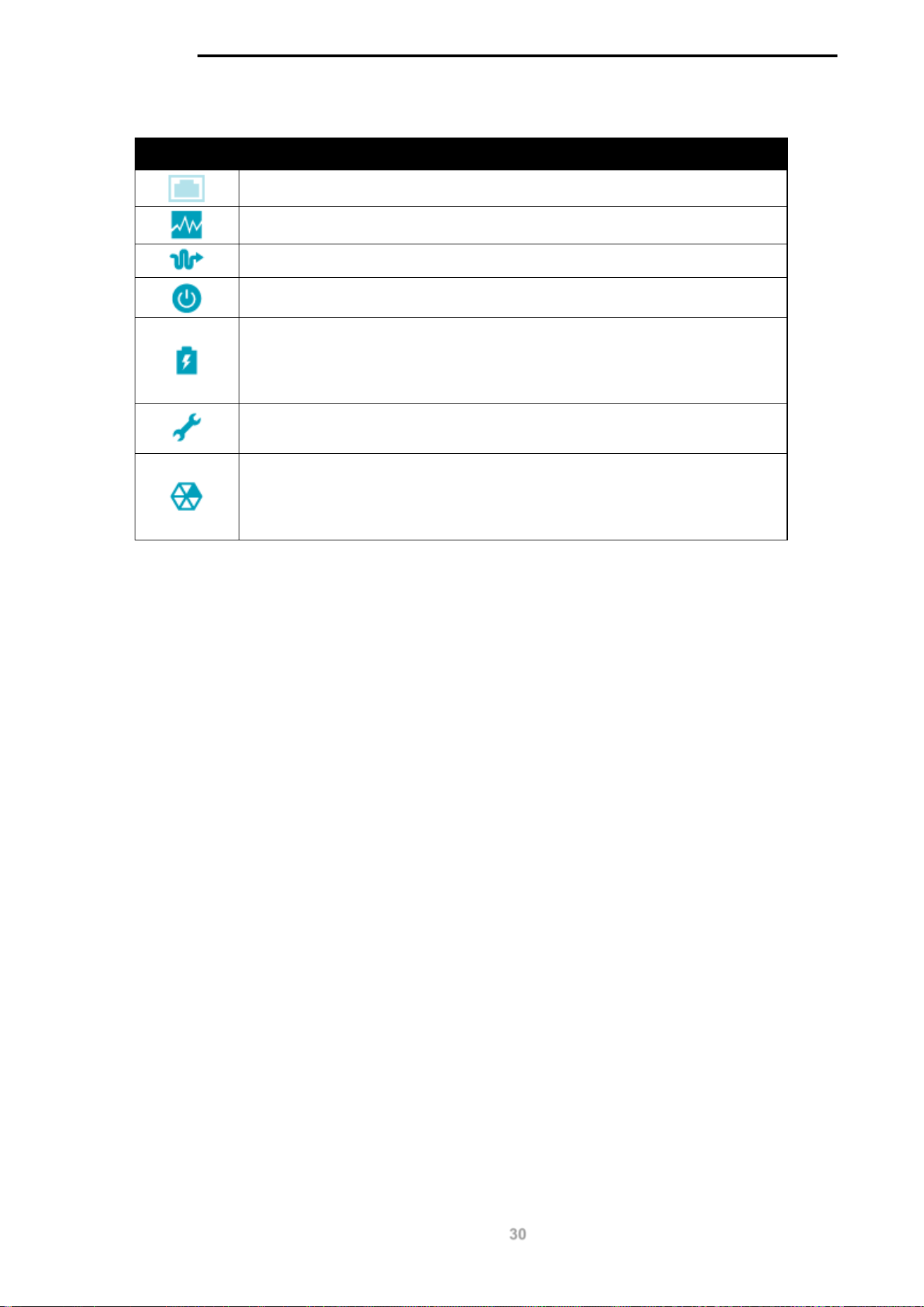
Hover-over each field to get more information about each value. A breakdown of each field is below:
Icon Description
The port number of the port.
The total inbound throughput for the port on the switch (measured in Mbps).
The cable length (in meters), taken from the Health Diagnostics page.
The PoE status for the port (PoE on or off).
The PoE consumption of the port. This is listed as one negative integer and
one positive integer. A negative value for PoE means that power is being
consumed by the port. The positive integer is the PoE budget for PoE
standard in use.
The Loopback Detection status. If a loop is detected, the icon will change to
include a link to the Health Diagnostics page.
The Group Details page. If an ONVIF device is detected as being connected
to the port, the icon changes to include a link to the Group Details page. If a
device is connected that is not ONVIF compatible, a drop-down menu will be
available to define the type of device connected.
D-Link DGS-1100 MP/MPP Series Switch User Manual
31
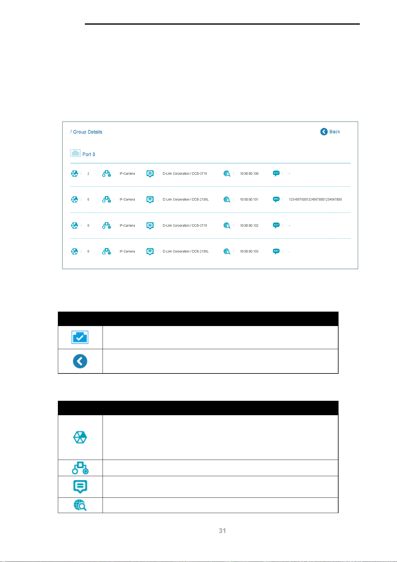
Group Details
The Group Details page lists the devices connected to a specific port. Only devices that have been
recognized as supporting ONVIF or NVRs will be displayed.
To view the following window, click on the Port Information link in the navigation menu and then
click on the Group Details link for a port that has recognized devices connected to it:
Figure 6-2 Group Details Window
The port number that the Group Details apply to is listed at the top of the page. The icon descriptions
are as follows:
Icon Description
The port number that the Group Details apply to.
Click to go back to the Port Information page.
Hover-over each field to get more information about each value. A breakdown of each field is below:
Icon Description
The Group Number that the device belongs to. All devices managed by an
NVR belong to the same Group Number. These are assigned sequentially,
with NVR1 having Group Number 1. If an NVR is removed, the Group
Numbers will be updated accordingly (if NVR1 is removed then Group
Number 2 will become Group Number 1).
The device type. This can be an IP-Camera or NVR.
The Model name of the IP-Camera. Nothing is displayed in this field if an
NVR is connected.
The IP address of the IP-Camera or NVR.

D-Link DGS-1100 MP/MPP Series Switch User Manual
32
The device description. This can be edited on the IP-Camera Information
page or NVR Information page.
D-Link DGS-1100 MP/MPP Series Switch User Manual
33
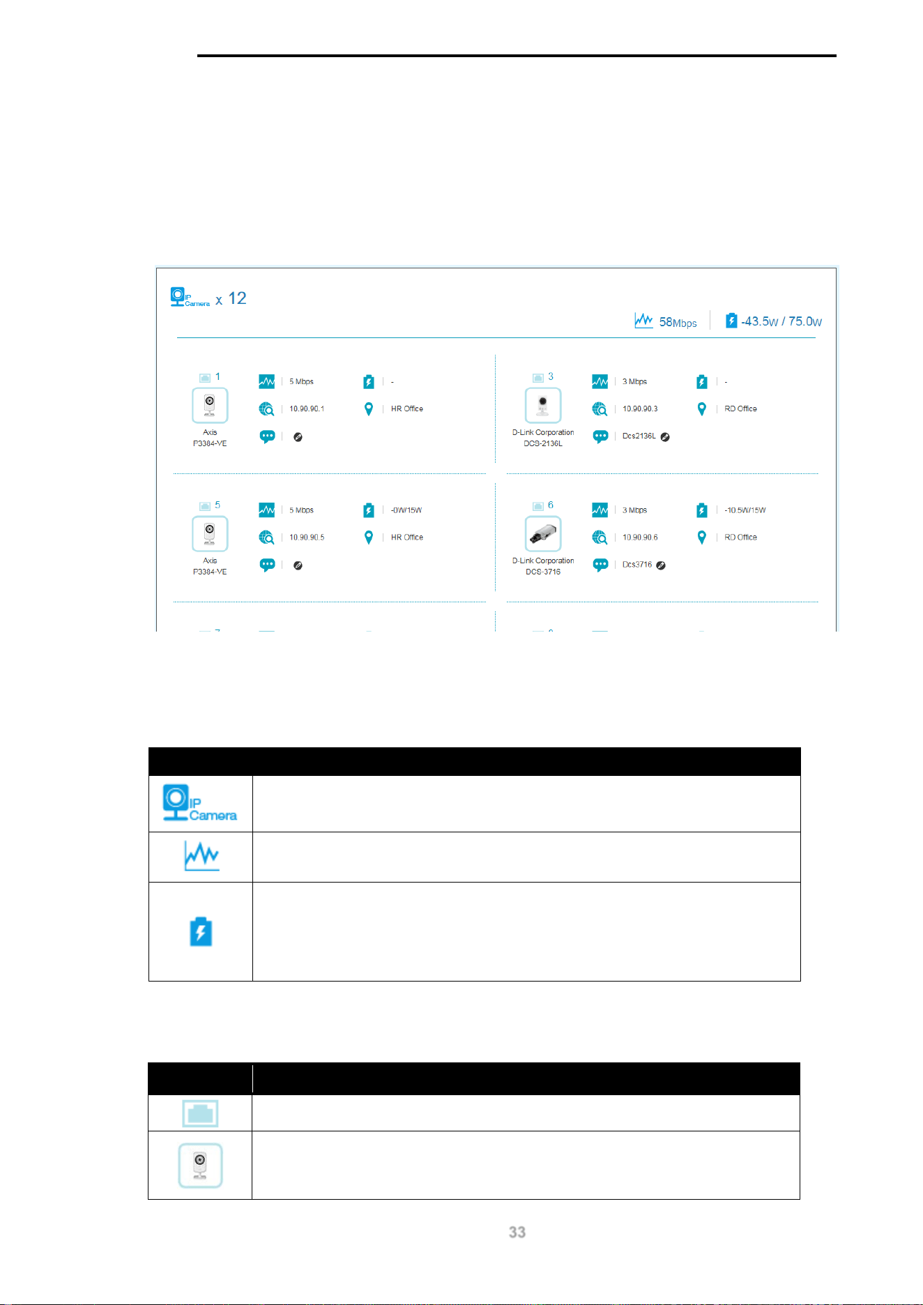
7. IP-Camera Information
The IP-Camera Information section provides information on each camera connected to the switch.
It features the port number, device type, throughput, IP address and other information such as port
description, power consumption and location.
To view the following window, click on the IP-Camera Information link in the navigation menu:
Figure 7-1 Port Information Window
The total device count, throughput and power consumption is listed at the top of the page. The icon
descriptions are as follows:
Icon Description
The total number of ONVIF IP-Cameras detected.
The total inbound throughput for all ports on the switch.
The PoE consumption of the switch. This is listed as one negative integer
and one positive integer. The negative integer is the power being consumed
by the PoE devices connected to the switch. The positive integer is the total
PoE budget for the ports currently using PoE, based on the type of PoE in
use.
Hover-over each field to get more information about each value. A breakdown of each field is
below:
Icon Description
The port number of the port.
The device icon or photo. A generic photo will displayed for a non-D-Link
ONVIF camera. A D-Link-specific photo will be displayed for a D-Link ONVIF
camera.
D-Link DGS-1100 MP/MPP Series Switch User Manual
34
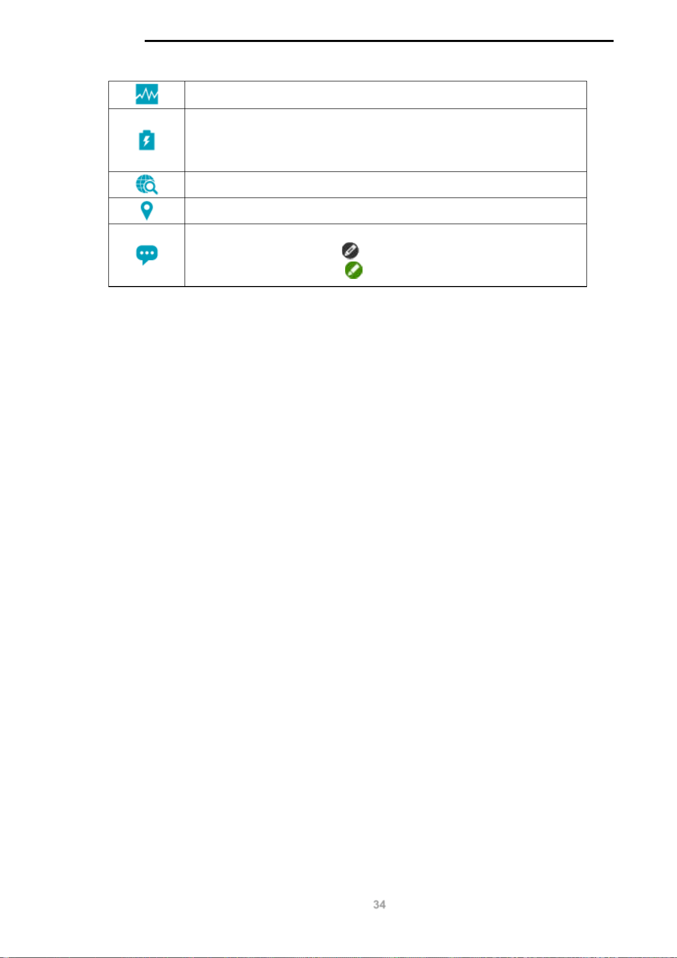
The total inbound throughput for the port on the switch (measured in Mbps).
The PoE consumption of the port. This is listed as one negative integer and
one positive integer. A negative value for PoE means that power is being
consumed by the port. The positive integer is the PoE budget for PoE
standard in use.
The IP address of the IP-Camera.
The location of the IP-Camera.
The description of the IP-Camera. This can be edited by clicking the black
pencil icon next to the field ( ) and then the green pencil icon when the
description has been entered ( ).
D-Link DGS-1100 MP/MPP Series Switch User Manual
35
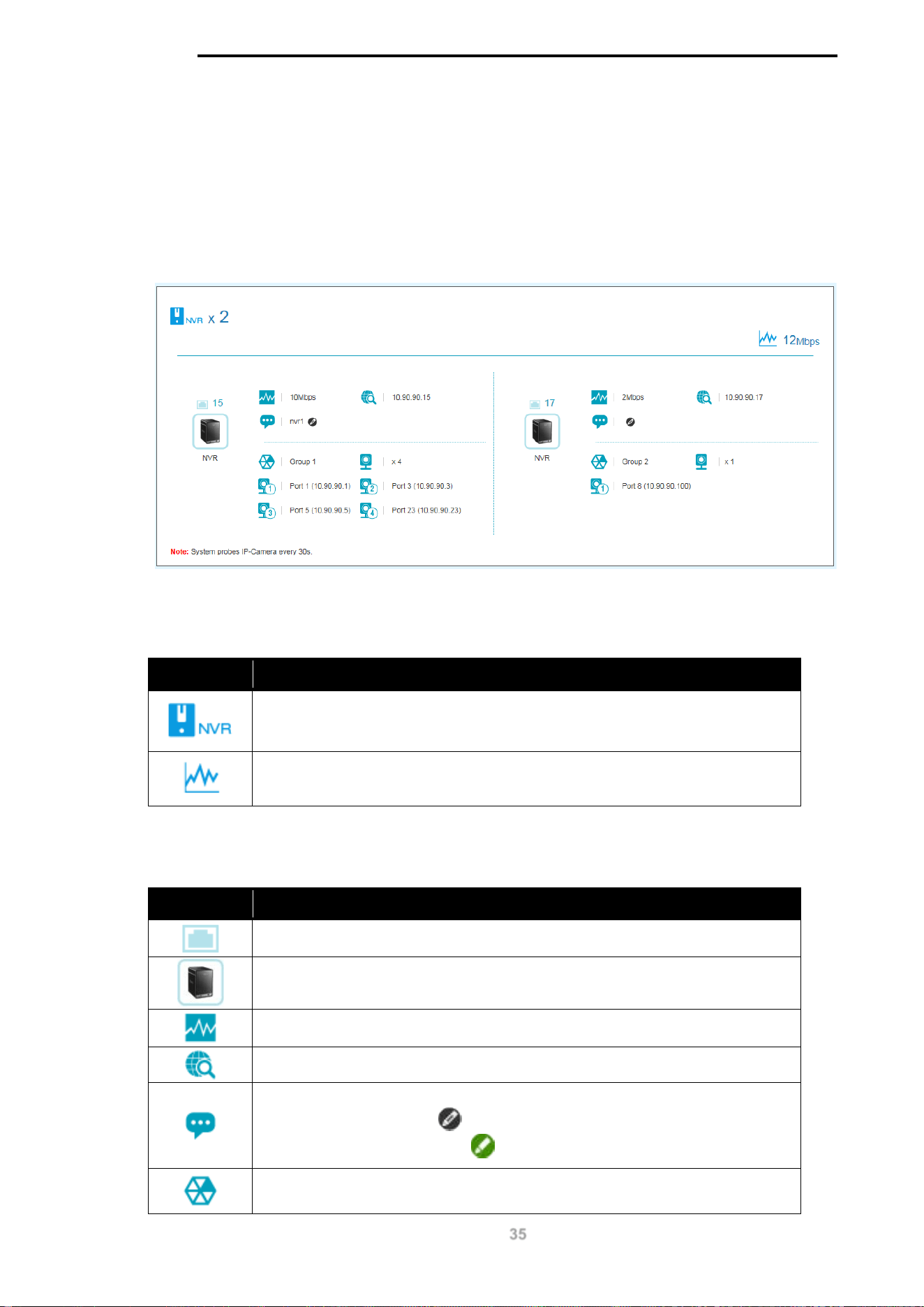
8. NVR Information
The NVR Information section provides information on each NVR connected to the switch. It
features the port number, throughput, IP address and information relating to the cameras
connected to the NVR, such as the group name, total number of cameras and the port and IP
address of each camera. Hover-over each field to get more information about each value.
To view the following window, click on the NVR Information link in the navigation menu:
Figure 8-1 NVR Information Window
The total number of NVRs and the total throughput is listed at the top of the page. The icon
descriptions are as follows:
Icon Description
The total number of NVRs detected.
The total inbound throughput for all ports on the switch.
Hover-over each field to get more information about each value. A breakdown of each field is
below:
Icon Description
The port number of the port.
The device icon or photo. A generic photo is displayed for all NVR types.
The total inbound throughput for the port on the switch (measured in Mbps).
The IP address of the NVR.
The Description of the NVR. This can be edited by clicking the black pencil
icon next to the field (
) and then the green pencil icon when the
description has been entered ( ).
The Group Number that a device belongs to. All devices managed by an
NVR belong to the same Group Number. These are assigned sequentially,

D-Link DGS-1100 MP/MPP Series Switch User Manual
36
with NVR1 having Group Number 1. If an NVR is removed, the Group
Numbers will be updated accordingly (if NVR1 is removed then Group
Number 2 will become Group Number 1).
The number of ONVIF IP-Cameras managed by this NVR.
Information relating to an IP-Camera in the group, such as port number and
IP address.
D-Link DGS-1100 MP/MPP Series Switch User Manual
37
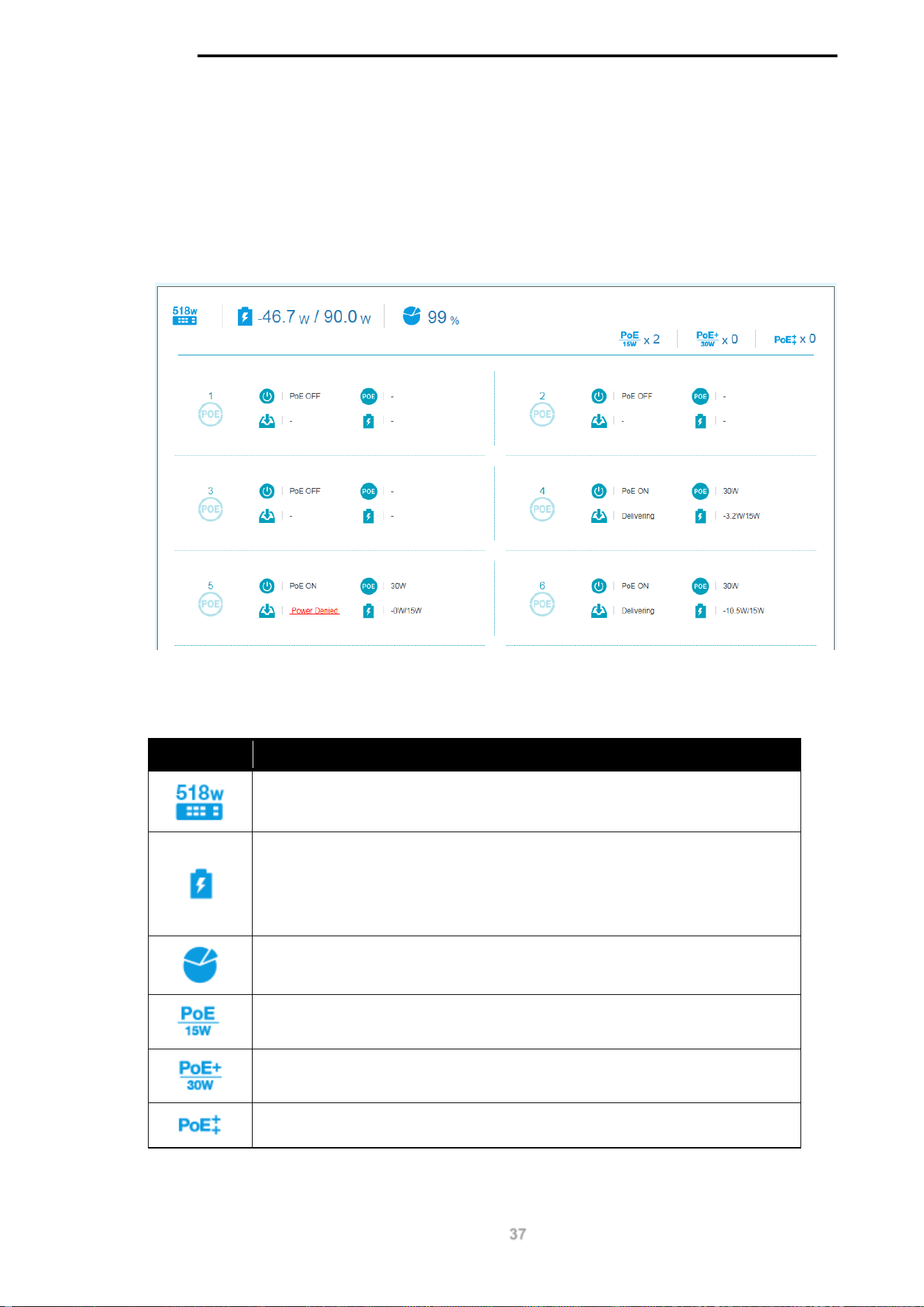
9. PoE Information
The PoE Information section provides information on the PoE usage of each port. The port number,
PoE status, health status, PoE budget and power consumption is listed for each port. It is possible
to click on the health status to be re-directed to the Health Diagnostic page. Hover-over each field
to get more information about each value.
To view the following window, click on the PoE Information link in the navigation menu:
Figure 9-1 PoE Information Window
The total power budget, power consumption, power budget consumption and the types of PoE in
use are listed at the top of the page. The icon descriptions are as follows:
Icon Description
The total PoE power budget.
The PoE consumption of the switch. This is listed as one negative integer
and one positive integer. The negative integer is the power being consumed
by the PoE devices connected to the switch. The positive integer is the total
PoE budget for the ports currently using PoE, based on the type of PoE in
use.
The current utilization of PoE power budget.
The number of 15 W PoE devices discovered.
The number of 30 W PoE devices discovered.
The number of 60/70 W PoE devices discovered.
D-Link DGS-1100 MP/MPP Series Switch User Manual
38
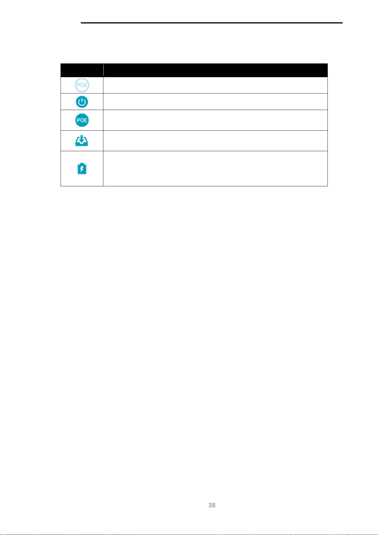
Hover-over each field to get more information about each value. A breakdown of each field is
below:
Icon Description
The port number of the port.
The PoE status for the port (PoE on or off).
The maximum PoE power budget for this port. This can be 30 W, or
30W/60W /75W if this port supports 4-pair PoE.
The PoE
state. If any fault is detected the icon changes to include a
description of the problem and a link to the Health Diagnostic page.
The PoE consumption of the port. This is listed as one negative integer and
one positive integer. A negative value for PoE means that power is being
consumed by the port. The positive integer is the PoE budget for PoE
standard in use.
D-Link DGS-1100 MP/MPP Series Switch User Manual
39
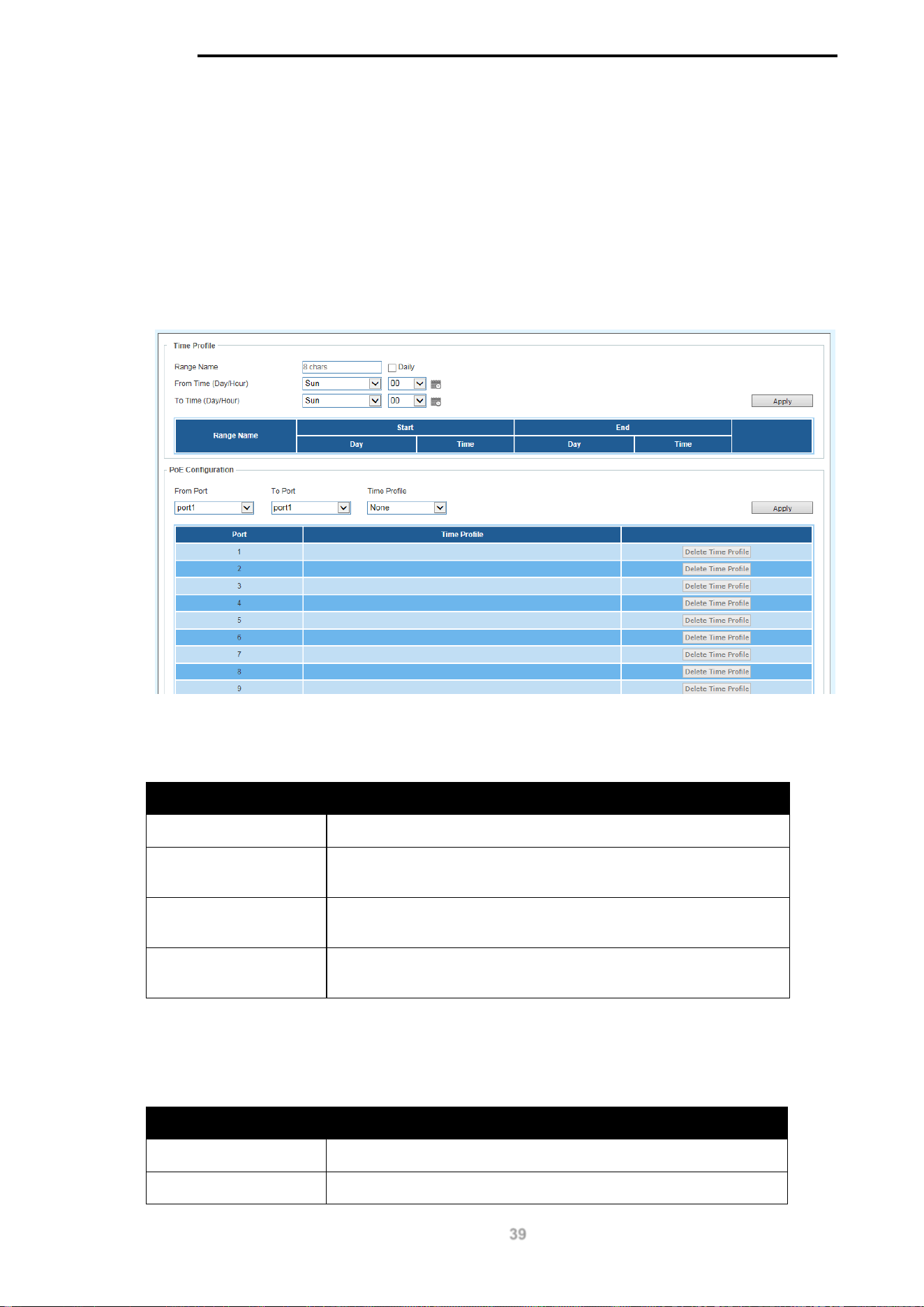
10. PoE Scheduling
PoE Scheduling is a feature which allows you to specify the amount of time that power is delivered
to a PoE port. This can be used to save power when devices are not in use, or as a security
feature to prevent wireless access from being available outside of business hours, for example. It is
possible to set a schedule name, a start time, an end time and which ports the PoE schedule
applies to.
To view the following window, click on the PoE Scheduling link in the navigation menu:
Figure 10-1 PoE Scheduling Window
The fields that can be configured for the Time Profile are described below:
Parameter Description
Range Name
Enter a descriptive name for the PoE schedule.
Daily
Check this tick-box to enable the schedule daily and gray-out the
day-of-week fields in the From Time/To Time sections.
From Time (Day/Hour) The start day and time for the PoE schedule. Click the calendar
icon to pick this using a graphic calendar tool.
To Time (Day/Hour) The end day and time for the PoE schedule. Click the calendar
icon to pick this using a graphic calendar tool.
Click the Apply button to accept the changes made.
The fields that can be configured for the PoE Configuration are described below:
Parameter Description
From Port The start port in the range that the PoE schedule will apply to.
To Port The end port in the range that the PoE schedule will apply to.

D-Link DGS-1100 MP/MPP Series Switch User Manual
40
Time Profile
The Time Profile created above.
Click the Apply button to accept the changes made.
D-Link DGS-1100 MP/MPP Series Switch User Manual
41
11. Time
Clock Settings
SNTP Settings
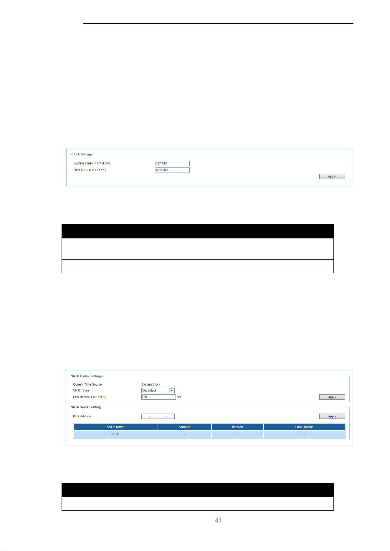
Clock Settings
This sub-menu is used to configure the time on the switch.
To view the following window, go to: Time > Clock Settings in the navigation menu:
Figure 11-1 Clock Settings Window
The fields that can be configured for the Clock Settings are described below:
Parameter Description
System Time
(HH:MM:SS)
Use this to set the system time in the format (HH:MM:SS).
Date (DD / MM / YYYY)
Use this to set the date, in the format (DD / MM / YYYY).
Click the Apply button to accept the changes made.
SNTP Settings
This sub-menu is used to configure an external time source on the switch. Simple Network Time
Protocol (SNTP) is a lightweight version of the NTP protocol and can be used to keep the system
clock in-sync by using a network-based time source.
To view the following window, go to: Time > SNTP Settings in the navigation menu:
Figure 11-2 SNTP Settings Window
The fields that can be configured for the SNTP Global Settings are described below:
Parameter Description
Current Time Source
Displays the current time source for the switch.

D-Link DGS-1100 MP/MPP Series Switch User Manual
42
SNTP State Set the SNTP state. Options are Enabled or Disabled.
Pool Interval (30-99999)
Set the synchronization interval for SNTP. The default is 720
seconds and the range is 30 – 99999 seconds.
Click the Apply button to accept the changes made.
The fields that can be configured for the SNTP Server Setting are described below:
Parameter Description
IPv4 Address
Enter the IP address of the SNTP server you would like to
synchronize with.
Click the Apply button to accept the changes made.
D-Link DGS-1100 MP/MPP Series Switch User Manual
43
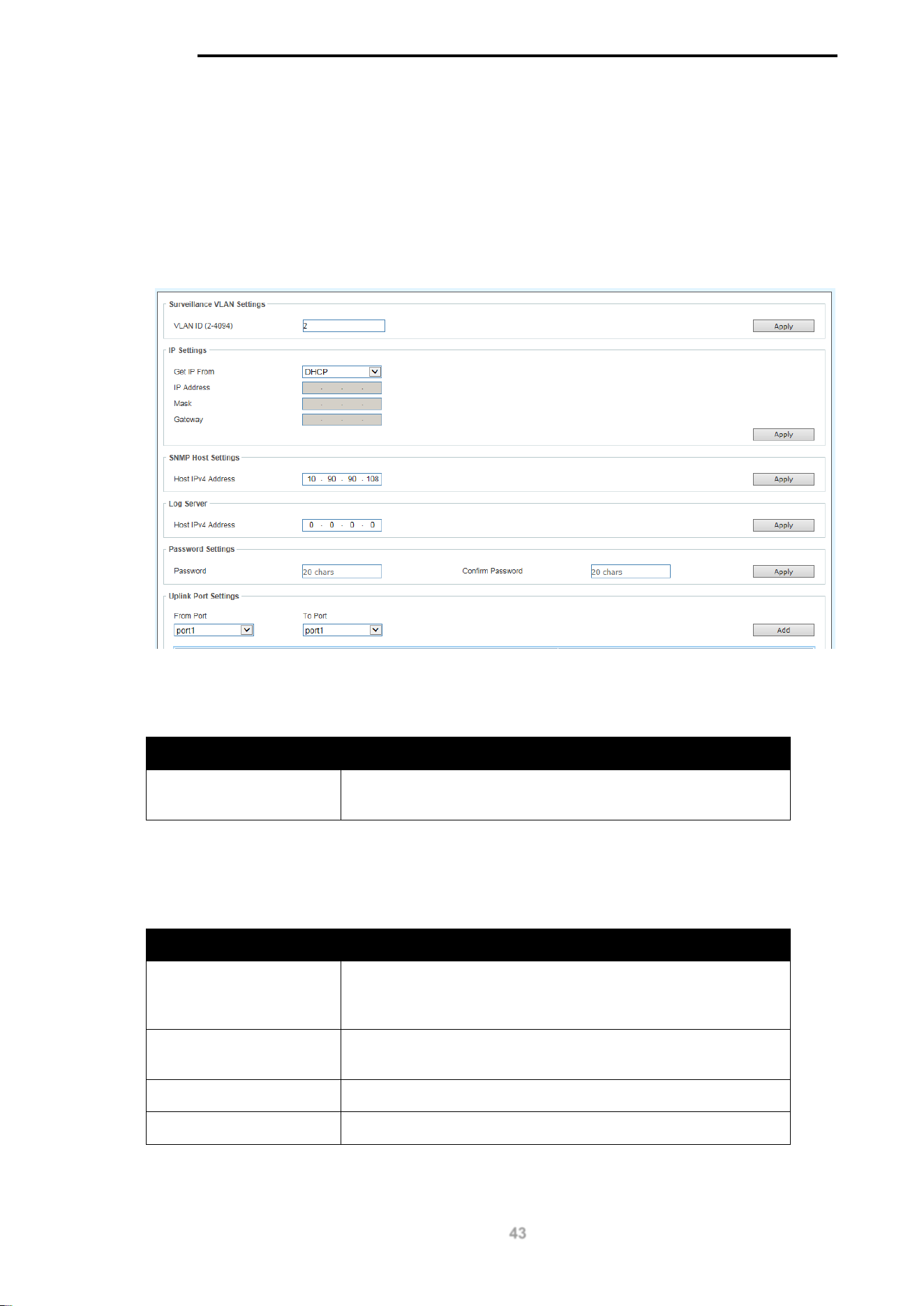
12. Surveillance Settings
The Surveillance Settings page is used to configure the settings for the Surveillance VLAN. This is
a VLAN dedicated for IP-Camera and surveillance traffic and can be used to manage surveillance
devices on the network.
To view the following window, click on the Surveillance Settings link in the navigation menu:
Figure 12-1 Surveillance Settings Window
The fields that can be configured for the Surveillance VLAN Settings are described below:
Parameter Description
VLAN ID (2-4094)
Enter a VLAN number for the surveillance VLAN in the range
(2-4094).
Click the Apply button to accept the changes made.
The fields that can be configured for the IP Settings are described below:
Parameter Description
Get IP From
Choose how the management IP for this VLAN is assigned to
the switch. Options are: DHCP, Static or BOOTP. If Static is
chosen, the following fields become available:
IP Address
Enter the IP address for the surveillance VLAN management
IP.
Mask
Enter the netmask for the surveillance VLAN management IP.
Gateway
Enter the gateway for the surveillance VLAN.
Click the Apply button to accept the changes made.

D-Link DGS-1100 MP/MPP Series Switch User Manual
44
The fields that can be configured for the SNMP Host Settings are described below:
Parameter Description
Host IPv4 Address
Enter the IP address of the SNMP Network Management
Server (NMS) which will receive SNMP Traps from this device.
Click the Apply button to accept the changes made.
The fields that can be configured for the Log Server are described below:
Parameter Description
Host IPv4 Address
Enter the IP address of the Syslog NMS which will receive
Syslog messages from this device.
Click the Apply button to accept the changes made.
The fields that can be configured for the Password Settings are described below:
Parameter Description
Password
Configure the password that will be used to restrict access to
the device via the Web UI. Password length is a maximum of
20 characters.
Confirm Password
Confirm the password that will be used to restrict access to the
device via the Web UI. Password length is a maximum of 20
characters.
Click the Apply button to accept the changes made.
The fields that can be configured for the Uplink Port Settings are described below:
Parameter Description
From Port Enter the start port in the range for Uplink Ports. These are
used for connecting the surveillance VLAN with other
switches.
To Port Enter the end port in the range for Uplink Ports. These are
used for connecting the surveillance VLAN with other
switches.
Click the Apply button to accept the changes made.
Click the Delete button to delete any entries in the list of uplink ports.

D-Link DGS-1100 MP/MPP Series Switch User Manual
45
NOTE: It is highly recommended that only uplink ports are connected to other
switches, as the IP-Camera discovery process is disabled on these ports. Use the
Uplink Port Settings section of the interface to define which ports connect to other
switches.
NOTE: The default uplink ports of the DGS-1100-
10MP/10MPP are port9 and
port10. The default uplink ports of DGS-1100-26MP/26MPP are port25 and port26.
D-Link DGS-1100 MP/MPP Series Switch User Manual
46
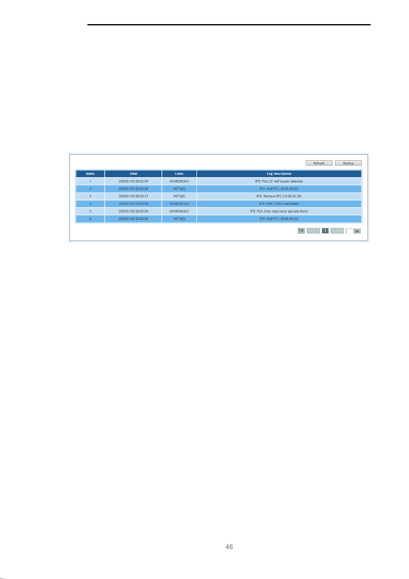
13. Surveillance Log
The Surveillance Log consists of a list of Syslog messages that have been generated by the switch.
Depending on whether a Syslog server has been defined in the Surveillance Settings section,
these may be local to the switch or copied to an external logging server. The messages are
ordered in date order with the latest message at the top of the list. Please consult an external
source for more information on Syslog logging levels.
To view the following window, click on the Surveillance Log link in the navigation menu:
Figure 13-1 Surveillance Log Window
Refresh: This will refresh the page.
Backup: This will allow you to save a local copy of the Syslog messages as a text file.
Enter a page number and click the Go button to navigate to a specific page when multiple pages
exist.
D-Link DGS-1100 MP/MPP Series Switch User Manual
47
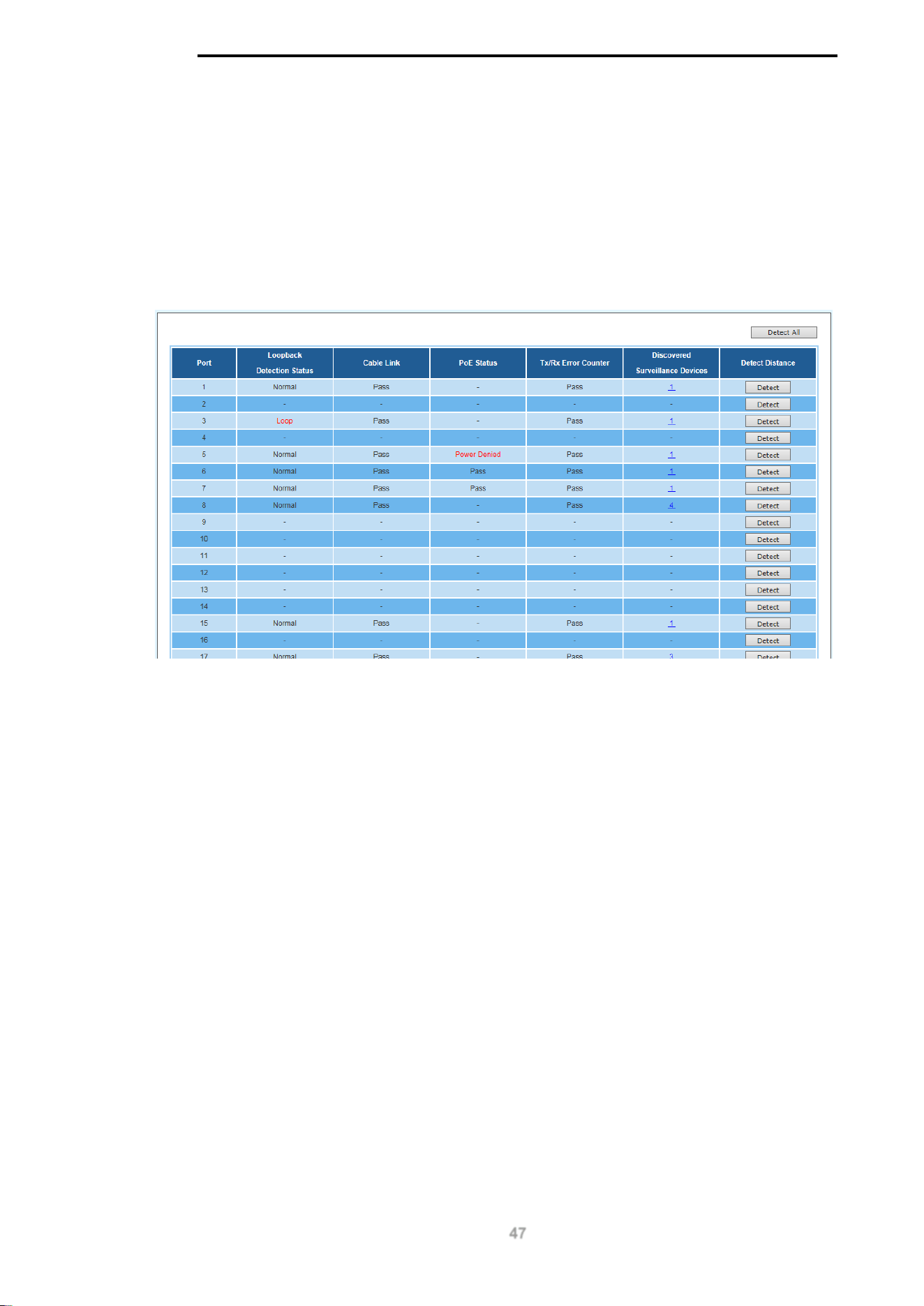
14. Health Diagnostic
The Health Diagnostic page is linked-to by the Port Information and PoE Information pages and
displays an overview of the port status. It contains the port number, Loopback Detection status,
Cable Link status, PoE Status, Tx/Rx Error Counter, number of Discovered Surveillance Devices
on the port (which links to the Group Details page) and the detected cable length. The page
automatically refreshes every 30 seconds.
To view the following window, click on the Health Diagnostic link in the navigation menu:
Figure 14-1 Health Diagnostic Window
Detect: Detect the cable length of the listed port.
Detect All: Detect the cable length of all ports.
D-Link DGS-1100 MP/MPP Series Switch User Manual
48
15. Save and Tools
Firmware Information
Firmware Upgrade & Backup
Configuration Restore & Backup
Reset
Reboot System
Firmware Information
This window is used to show firmware information.
To view the following window, click Tools > Firmware Information, as shown below:
Figure 15-1 Firmware Information window
Boot Up: Clicking the Boot Up button will set that firmware image as the active image to use upon
the next system start up.
NOTE: Changing the firmware only happens after the switch has been manually rebooted. In order
to boot with the newly selected firmware, make sure that the switch is rebooted.
Firmware Upgrade & Backup
NOTE: When upgrading the firmware on the DGS-1100 MP/MPP Series switch, only
the image not currently active can be upgraded. All DGS-1100 MP/MPP Series
switches come with two images, however only one can be active at any time. (e.g. If
image 1 is currently in use, only image 2 can be upgraded, and vice versa.)
NOTE: If the switch is in HTTPS mode, the firmware or configuration cannot be
upgraded using regular HTTP.
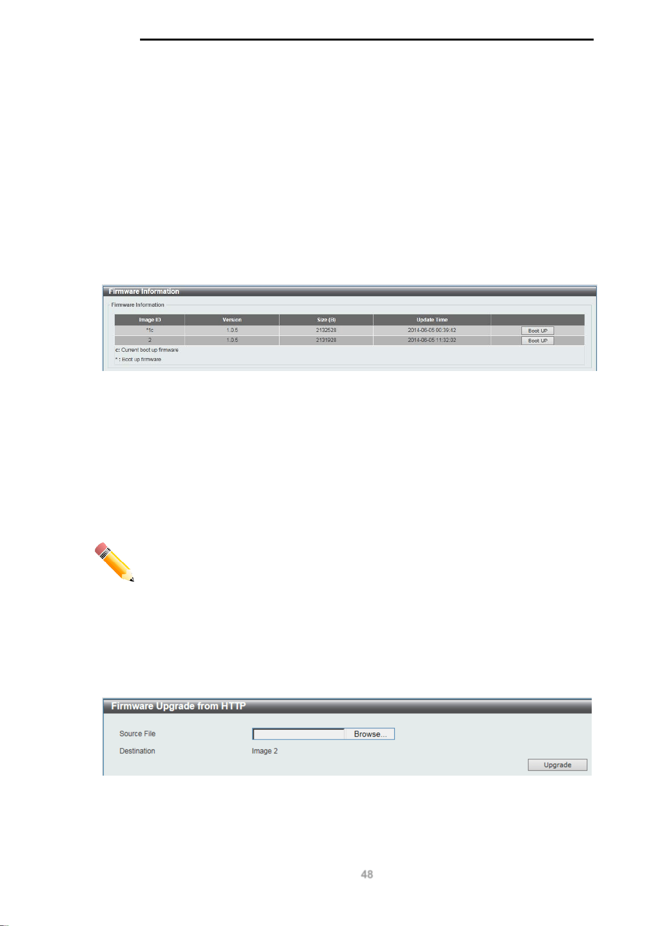
Firmware Upgrade from HTTP
This window is used to initiate a firmware upgrade from a local PC using HTTP.
To view the following window, click Tools > Firmware Upgrade & Backup > Firmware Upgrade
from HTTP, as shown below:
Figure 15-2 Firmware Upgrade from HTTP window
The fields that can be configured are described below:
D-Link DGS-1100 MP/MPP Series Switch User Manual
49
Parameter Description
Source File
Enter the source filename and path of the firmware file
located on the local PC. Alternatively click the Browse
button to navigate to the location of the firmware file located
on the local PC.
Click the Upgrade button to initiate the firmware upgrade.
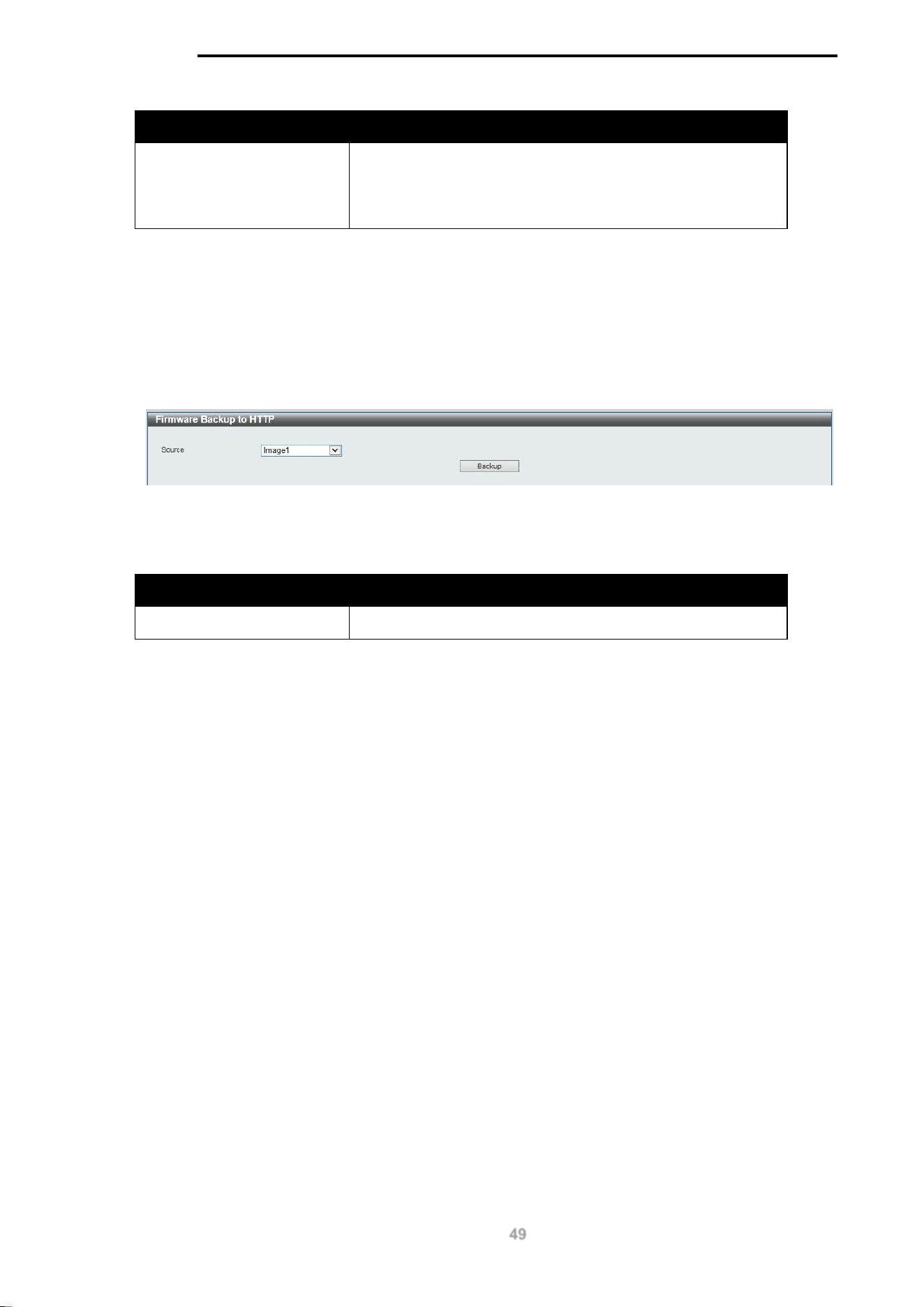
Firmware Backup to HTTP
This window is used to initiate a firmware backup to a local PC using HTTP.
To view the following window, click Tools > Firmware Upgrade & Backup > Firmware Backup to
HTTP, as shown below:
Figure 15-3 Firmware Backup to HTTP window
The fields that can be configured are described below:
Parameter Description
Source
Select the source image to use for the firmware backup.
Click the Backup button to initiate the firmware backup.
D-Link DGS-1100 MP/MPP Series Switch User Manual
50
Configuration Restore & Backup
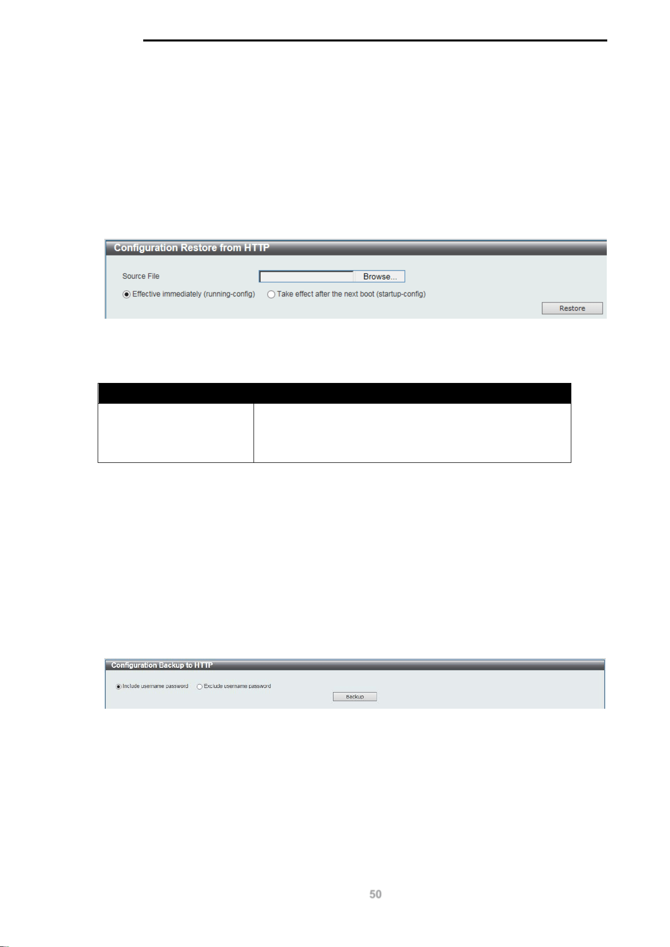
Configuration Restore from HTTP
This window is used to initiate a configuration restore from a local PC using HTTP.
NOTE: If the switch is in HTTPS mode, the firmware or configuration cannot be upgraded using
regular HTTP.
To view the following window, click Tools > Configuration Restore & Backup > Configuration
Restore from HTTP, as shown below:
Figure 15-4 Configuration Restore from HTTP window
The fields that can be configured are described below:
Parameter Description
Source File
Enter the source filename and path of the configuration file
located on the local PC. Alternatively click the Browse button
to navigate to the location of the configuration file located on
the local PC.
Click the Restore button to initiate the configuration restore.
Click Effective immediately (running-config) to have the uploaded configuration loaded
immediately.
Click Take effect after the next boot (startup-config) to load the configuration after the switch has
been rebooted.
Configuration Backup to HTTP
This window is used to initiate a configuration file backup to a local PC using HTTP.
To view the following window, click Tools > Configuration Restore & Backup > Configuration
Backup to HTTP, as shown below:
Figure 15-5 Configuration Backup to HTTP window
Select Include username password to save the switch user accounts and passwords to the backup
file.
Select Exclude username password to save the switch user accounts and passwords to the
backup file.
Click the Backup button to initiate the configuration file backup.
D-Link DGS-1100 MP/MPP Series Switch User Manual
51
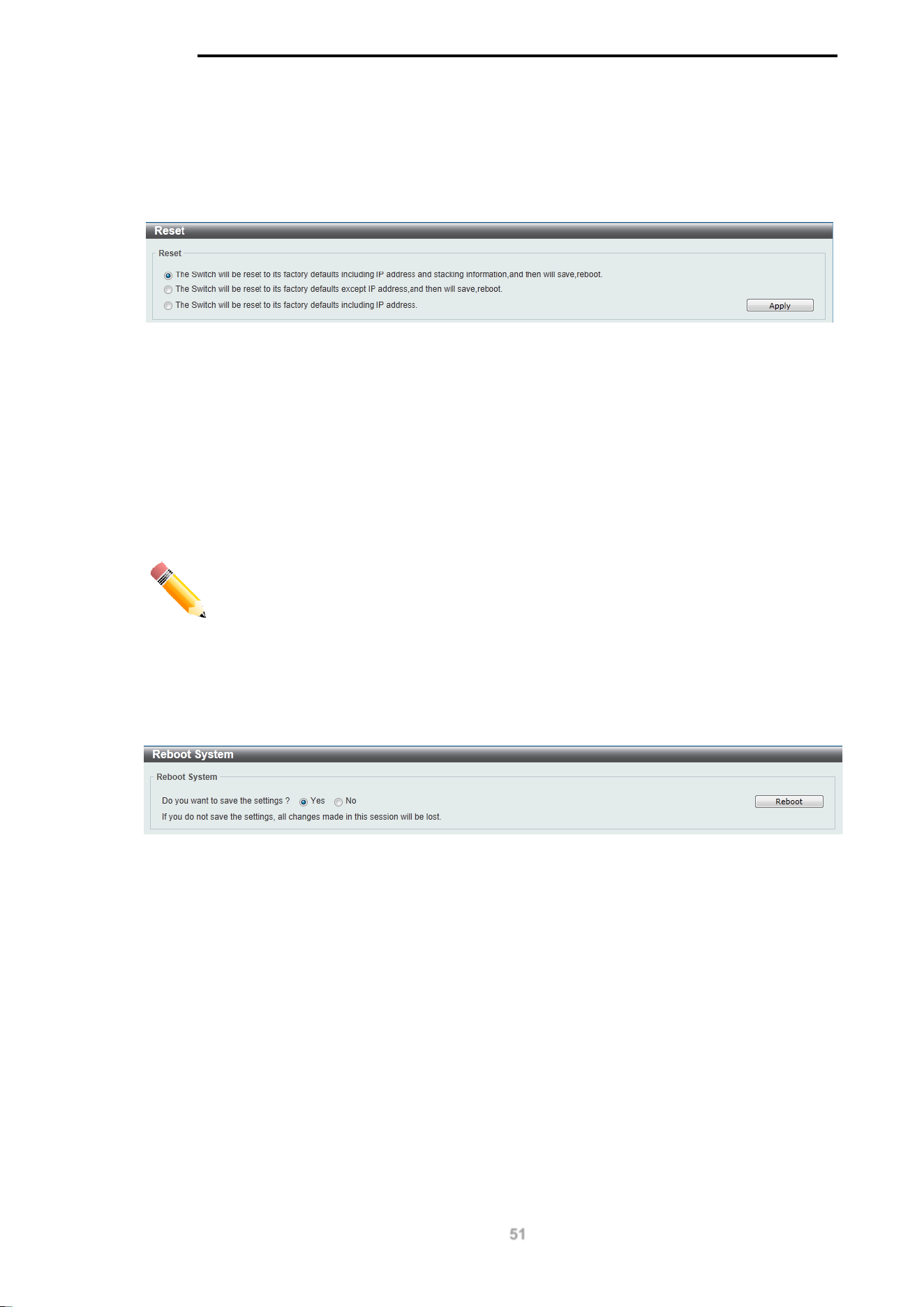
Reset
This window is used to reset the switch’s configuration to the factory default settings.
To view the following window, click Tools > Reset, as shown below:
Figure 15-6 Reset window
Select the The Switch will be reset to its factory defaults including IP address and stacking
information, and the will save, reboot option to reset the switch’s configuration to its factory
default settings.
Select the The Switch will be reset to its factory default except IP address, and then will save,
reboot option to reset the switch’s configuration to its factory default settings. This option will
exclude the IP address from being changed.
Select the The Switch will be reset to its factory defaults including IP address option to reset
the switch’s configuration to its factory default settings.
Click the Apply button to initiate the factory default reset and reboot the switch.
NOTE: Performing a factory reset in one version of the interface (Standard Mode
or Surveillance Mode) will cause settings to be reset in the other version of the
interface.
Reboot System
This window is used to reboot the switch and alternatively save the configuration before doing so. To
view the following window, click Tools > Reboot System, as shown below:
Figure 15-7 Reboot System window
When rebooting the switch, any configuration changes that was made during this session, will be lost
unless the Yes option is selected when asked to save the settings.
Click the Reboot button to alternatively save the settings and reboot the switch.
D-Link DGS-1100 MP/MPP Series Switch User Manual
52
Figure 15-8 Reboot System - Rebooting window

D-Link DGS-1100 MP/MPP Series Switch User Manual
53
16. Appendix A - Ethernet Technology
This chapter will describe the features of the D-Link DGS-1100 MP/MPP Series switch and provide
some background information about Ethernet/Fast Ethernet/Gigabit Ethernet switching technology.
Gigabit Ethernet Technology
Gigabit Ethernet is an extension of IEEE 802.3 Ethernet utilizing the same packet structure, format,
and support for CSMA/CD protocol, full duplex, and management objects, but with a tenfold increase
in theoretical throughput of over 100-Mbps Fast Ethernet and a hundredfold increase over 10-Mbps
Ethernet. Since it is compatible with all 10-Mbps and 100-Mbps Ethernet environments, Gigabit
Ethernet provides a straightforward upgrade without wasting existing investments in hardware,
software, or trained personnel.
The increased speed and extra bandwidth offered by Gigabit Ethernet is essential to help solving
network bottlenecks that frequently develop as more advanced computer users and newer
applications continue to demand greater network resources. Upgrading key components, such as
backbone connections and servers to Gigabit Ethernet technology can greatly improve network
response times as well as significantly speed up the traffic between subnets.
Gigabit Ethernet enables fast optical fiber connections to support video conferencing, complex
imaging, and similar data-intensive applications. Likewise, since data transfers occur 10 times faster
than Fast Ethernet, servers outfitted with Gigabit Ethernet NIC’s are able to perform 10 times the
number of operations in the same amount of time.
In addition, the phenomenal bandwidth delivered by Gigabit Ethernet is the most cost-effective
method to take advantage of today and tomorrow’s rapidly improving switching and routing
internetworking technologies. And with expected advances in the coming years in silicon technology
and digital signal processing that will enable Gigabit Ethernet to eventually operate over unshielded
twisted-pair (UTP) cabling, outfitting your network with a powerful 1000-Mbps-capable
backbone/server connection which will create a flexible foundation for the next generation of network
technology products.
Fast Ethernet Technology
The growing importance of LANs and the increasing complexity of desktop computing applications
are fueling the need for high performance networks. A number of high-speed LAN technologies have
been proposed to provide greater bandwidth and improve client/server response times. Among
them, 100BASE-T (Fast Ethernet) provides a non-disruptive, smooth evolution from the current
10BASE-T technology. The non-disruptive and smooth evolution nature, and the dominating
potential market base, virtually guarantees cost-effective and high performance Fast Ethernet
solutions.
100Mbps Fast Ethernet is a standard specified by the IEEE 802.3 LAN committee. It is an extension
of the 10Mbps Ethernet standard with the ability to transmit and receive data at 100Mbps, while
maintaining the CSMA/CD Ethernet protocol. Since the 100Mbps Fast Ethernet is compatible with all
other 10Mbps Ethernet environments, it provides a straightforward upgrade and utilizes existing
investments in hardware, software, and personnel training.
Switching Technology
Another approach to push beyond the limits of Ethernet technology is the development of switching
technology. A switch bridges Ethernet packets at the MAC address level of the Ethernet protocol
transmitting among connected Ethernet or Fast Ethernet LAN segments.
Switching is a cost-effective way of increasing the total network capacity available to users on a local
area network. A switch increases capacity and decreases network loading by dividing a local area

D-Link DGS-1100 MP/MPP Series Switch User Manual
54
network into different segments which won’t compete with each other for network transmission
capacity.
The switch acts as a high-speed selective bridge between the individual segments. The switch,
without interfering with any other segments, automatically forwards traffic that needs to go from one
segment to another. By doing this the total network capacity is multiplied, while still maintaining the
same network cabling and adapter cards.

D-Link DGS-1100 MP/MPP Series Switch User Manual
55
17. Appendix B - Technical Specifications
Hardware
Specifications
Key Components /
Performance
Switching Capacity:
- DGS-1100-10MP: 20Gbps
- DGS-1100-10MPP: 20Gbps
- DGS-1100-26MP: 52Gbps
- DGS-1100-26MPP: 52Gbps
Max. Forwarding Rate:
- DGS-1100-10MP: 14.88Mpps
- DGS-1100-10MPP: 14.88Mpps
- DGS-1100-26MP: 38.69Gbps
- DGS-1100-26MPP: 38.69Gbps
Forwarding Mode: Store and Forward
Packet Buffer memory:
- DGS-1100-10MP: 1.5Mbytes
- DGS-1100-10MPP: 1.5Mbytes
- DGS-1100-26MP: 1.5Mbytes
- DGS-1100-26MPP: 1.5Mbytes
Flash Memory: 16M Byte
Port Functions
10/100/1000BaseTX ports compliant with
the following standards:
- IEEE 802.3
- IEEE 802.3u
- IEEE 802.3ab
- IEEE 802.3at
- IEEE 802.3af
- IEEE 802.3bt (DGS-1100 MPP Series
only)
- Supports Full/half-Duplex operations at
10/100Mbps
- Supports Full-Duplex operation at
1000Mbps
- Supports IEEE 802.3x Flow Control
- Support Auto-Negotiation
- Compliant to IEEE 802.3az Energy
Efficiency Ethernet.
SFP ports compliant with the following
standards:
- IEEE 802.3z compliance
Physical &
Environment
Power input: 100~240 VAC, 50/60Hz,
internal universal power supply
Acoustic Value:
- DGS-1100-10MP: 45.4dB
- DGS-1100-10MPP: 53dB
- DGS-1100-26MP: 56dB
- DGS-1100-26MPP: 56dB
Operation Temperature: -5-50°C
Storage Temperature: -40-70°C
Operation Humidity: 0% ~ 95% RH
Storage Humidity: 0% ~ 95% RH
Emission (EMI)
Certifications
FCC class A
CE Class A
VCCI Class A
BSMI
CCC
Safety Certifications
CUL, LVD, CB, CCC, BSMI
Features
L2 Features
16K MAC address
Loopback Detection
Port Mirroring
Link Aggregation
Cable Diagnostics
Spanning Tree
Ethernet Ring Protection Switching
(ERPS)
L2 Multicasting
IGMP Snooping
VLAN
802.1Q VLAN standard
Port-Based VLAN
Surveillance VLAN
Voice VLAN

D-Link DGS-1100 MP/MPP Series Switch User Manual
56
Asymmetric VLAN
Quality of Service
(QoS)
802.1p priority
4 queues
Bandwidth Control
Security
Storm Control
DoS Attack Prevention
SSL
D-Link Safeguard
DHCP Snooping
Management
Web-based GUI or D-Link Network
Assistant
Configuration backup / restoration via
Web-based management
Firmware backup & upgrade via Web-
based management
Reset, Reboot system
Factory reset by pressing reset button
SNMP, LLDP, Dual Image, 2 level user
account, SNTP
Power Saving
IEEE 802.3az Compliant (Energy Efficient
Ethernet)
D-Link Green Technologies
- Power saving by link status
- Power Saving by LED Shut-Off
- Power Saving by Port Shut-Off
- Power Saving by System Hibernation
Surge Protection
All PoE ports support 6 KV surge
protection

D-Link DGS-1100 MP/MPP Series Switch User Manual
57
18. Appendix C – Rack mount Instructions
Safety Instructions - Rack Mount Instructions - The following or similar rack-mount instructions are
included with the installation instructions:
A) Elevated Operating Ambient - If installed in a closed or multi-unit rack assembly, the operating
ambient temperature of the rack environment may be greater than room ambient. Therefore,
consideration should be given to installing the equipment in an environment compatible with the
maximum ambient temperature (Tma) specified by the manufacturer.
B) Reduced Air Flow - Installation of the equipment in a rack should be such that the amount of air
flow required for safe operation of the equipment is not compromised.
C) Mechanical Loading - Mounting of the equipment in the rack should be such that a hazardous
condition is not achieved due to uneven mechanical loading.
D) Circuit Overloading - Consideration should be given to the connection of the equipment to the
supply circuit and the effect that overloading of the circuits might have on overcurrent protection and
supply wiring. Appropriate consideration of equipment nameplate ratings should be used when
addressing this concern.
E) Reliable Earthing - Reliable earthing of rack-mounted equipment should be maintained. Particular
attention should be given to supply connections other than direct connections to the branch circuit
(e.g. use of power strips)

D-Link DGS-1100 Series Switch User Manual