
EnglishDeutschFrançaisEspañolPortuguêsItalianoРусский日本語
Owner’s Manual
Bedienungsanleitung
Mode d’emploi
Manual de instrucciones
Manual do Proprietário
Manuale di istruzioni
Руководство пользователя
取扱説明書
JA
RU
IT
PT
ES
FR
DE
EN
L
2
SWITCH
SWP2
-
10MMF
SWP2
-
10SMF
SWP2 Owner’s Manual
2
Explanation of Graphical Symbols
Explication des symboles
The lightning flash with arrowhead symbol within an equilateral triangle is intended to alert the user to the presence of uninsulated “dangerous
voltage” within the product’s enclosure that may be of sufficient magnitude to constitute a risk of electric shock to persons.
L’éclair avec une flèche à l’intérieur d’un triangle équilatéral est destiné à attirer l’attention de l’utilisateur sur la présence d’une « tension
dangereuse » non isolée à l’intérieur de l’appareil, pouvant être suffisamment élevée pour constituer un risque d’électrocution.
The exclamation point within an equilateral triangle is intended to alert the user to the presence of important operating and maintenance
(servicing) instructions in the literature accompanying the product.
Le point d’exclamation à l’intérieur d’un triangle équilatéral est destiné à attirer l’attention de l’utilisateur sur la présence d’instructions
importantes sur l’emploi ou la maintenance (réparation) de l’appareil dans la documentation fournie.
IMPORTANT SAFETY INSTRUCTIONS
1 Read these instructions.
2 Keep these instructions.
3 Heed all warnings.
4 Follow all instructions.
5 Do not use this apparatus near water.
6 Clean only with dry cloth.
7 Do not block any ventilation openings. Install in accordance with the
manufacturer’s instructions.
8 Do not install near any heat sources such as radiators, heat registers,
stoves, or other apparatus (including amplifiers) that produce heat.
9 Do not defeat the safety purpose of the polarized or grounding-type
plug. A polarized plug has two blades with one wider than the other.
A grounding type plug has two blades and a third grounding prong.
The wide blade or the third prong are provided for your safety. If the
provided plug does not fit into your outlet, consult an electrician for
replacement of the obsolete outlet.
10 Protect the power cord from being walked on or pinched particularly
at plugs, convenience receptacles, and the point where they exit from
the apparatus.
11 Only use attachments/accessories specified by the manufacturer.
12 Use only with the cart, stand, tripod, bracket, or table
specified by the manufacturer, or sold with the
apparatus. When a cart is used, use caution when
moving the cart/apparatus combination to avoid
injury from tip-over.
13 Unplug this apparatus during lightning storms or
when unused for long periods of time.
14 Refer all servicing to qualified service personnel. Servicing is
required when the apparatus has been damaged in any way, such as
power-supply cord or plug is damaged, liquid has been spilled or
objects have fallen into the apparatus, the apparatus has been
exposed to rain or moisture, does not operate normally, or has been
dropped.
PRÉCAUTIONS CONCERNANT LA
SÉCURITÉ
1 Lire ces instructions.
2 Conserver ces instructions.
3 Tenir compte de tous les avertissements.
4 Suivre toutes les instructions.
5 Ne pas utiliser ce produit à proximité d’eau.
6 Nettoyer uniquement avec un chiffon propre et sec.
7 Ne pas bloquer les orifices de ventilation. Installer l’appareil
conformément aux instructions du fabricant.
8 Ne pas installer l’appareil à proximité d’une source de chaleur comme
un radiateur, une bouche de chaleur, un poêle ou tout autre appareil
(y compris un amplificateur) produisant de la chaleur.
9 Ne pas modifier le système de sécurité de la fiche polarisée ou de la
fiche de terre. Une fiche polarisée dispose de deux broches dont une
est plus large que l’autre. Une fiche de terre dispose de deux broches
et d’une troisième pour le raccordement à la terre. Cette broche plus
large ou cette troisième broche est destinée à assurer la sécurité de
l’utilisateur. Si la fiche équipant l’appareil n’est pas compatible avec
les prises de courant disponibles, faire remplacer les prises par un
électricien.
10 Acheminer les cordons d’alimentation de sorte qu’ils ne soient pas
piétinés ni coincés, en faisant tout spécialement attention aux fiches,
prises de courant et au point de sortie de l’appareil.
11 Utiliser exclusivement les fixations et accessoires spécifiés par le
fabricant.
12 Utiliser exclusivement le chariot, le stand, le trépied,
le support ou la table recommandés par le fabricant
ou vendus avec cet appareil. Si l’appareil est posé
sur un chariot, déplacer le chariot avec précaution
pour éviter tout risque de chute et de blessure.
13 Débrancher l’appareil en cas d’orage ou lorsqu’il
doit rester hors service pendant une période
prolongée.
14 Confier toute réparation à un personnel qualifié. Faire réparer
l’appareil s’il a subi tout dommage, par exemple si la fiche ou le
cordon d’alimentation est endommagé, si du liquide a coulé ou des
objets sont tombés à l’intérieur de l’appareil, si l’appareil a été exposé
à la pluie ou à de l’humidité, si l’appareil ne fonctionne pas
normalement ou est tombé.
CAUTION:
TO REDUCE THE RISK OF ELECTRIC SHOCK,
DO NOT REMOVE COVER (OR BACK).
NO USER-SERVICEABLE PARTS INSIDE.
REFER SERVICING TO QUALIFIED SERVICE PERSONNEL.
ATTENTION :
POUR RÉDUIRE LES RISQUES D'ÉLECTROCUTION, NE PAS RETIRER
LE CAPOT (OU LE DOS). NE CONTIENT PAS DE PIÈCES NÉCESSITANT
L'INTERVENTION DE L'UTILISATEUR. POUR TOUTE INTERVENTION,
FAIRE APPEL À DES PROFESSIONNELS QUALIFIÉS.
ATTENTION
RISQUE DE CHOC
ELECTRIQUE-NE PAS OUVRIR
The above warning is located on the top of the unit.
L’avertissement ci-dessus est situé sur le dessus de l’unité.
WARNING
TO REDUCE THE RISK OF FIRE OR ELECTRIC SHOCK, DO NOT
EXPOSE THIS APPARATUS TO RAIN OR MOISTURE.
AVERTISSEMENT
POUR RÉDUIRE LES RISQUES D’INCENDIE OU DE DÉCHARGE
ÉLECTRIQUE, N’EXPOSEZ PAS CET APPAREIL À LA PLUIE OU À
L’HUMIDITÉ.

SWP2 Owner’s Manual
3
1. IMPORTANT NOTICE: DO NOT MODIFY THIS UNIT!
This product, when installed as indicated in the instructions
contained in this manual, meets FCC requirements. Modifica-
tions not expressly approved by Yamaha may void your
authority, granted by the FCC, to use the product.
2. IMPORTANT: When connecting this product to accessories
and/or another product use only high quality shielded cables.
Cable/s supplied with this product MUST be used. Follow all
installation instructions. Failure to follow instructions could
void your FCC authorization to use this product in the USA.
3. NOTE: This product has been tested and found to comply
with the requirements listed in FCC Regulations, Part 15 for
Class “A” digital devices. Compliance with these require-
ments provides a reasonable level of assurance that your use
of this product, in a commercial environment, will not result in
harmful interference with other electronic devices. However,
operation of this product in a residential area is likely to cause
interference in some form. In this case you, the user, bear the
responsibility of correcting this condition.
This product generates/uses radio frequencies and, if not
installed and used according to the instructions found in the
users manual, may cause interference harmful to the opera-
tion of other electronic devices. Compliance with FCC regula-
tions does not guarantee that interference will not occur in all
installations. If this product is found to be the source of inter-
ference, which can be determined by turning the product
“OFF” and “ON”, please try to eliminate the problem by using
one of the following measures:
Relocate either the product generating the interference or the
device that is being affected by the interference.
Utilize power outlets that are on different branch (circuit
breaker or fuse) circuits or install AC line filter/s.
In the case of radio or TV interference, relocate/reorient the
antenna. If the antenna lead-in is 300 ohm ribbon lead,
change the lead-in to co-axial type cable.
If these corrective measures do not produce satisfactory
results, please contact the local retailer that is authorized to
distribute this type of product. If you can not locate the appro-
priate retailer, please contact Yamaha Corporation of Amer-
ica, Electronic Service Division, 6600 Orangethorpe Ave,
Buena Park, CA90620
The above statements apply ONLY to those products distrib-
uted by Yamaha Corporation of America or its subsidiaries.
(class A)
FCC INFORMATION (U.S.A.)
COMPLIANCE INFORMATION STATEMENT
(Supplierʼs declaration of conformity procedure)
Responsible Party: Yamaha Corporation of America
Address: 6600 Orangethorpe Ave. Buena Park CA 90620
Telephone: 714-522-9011
Type of Equipment: L2 Switch
Model Name: SWP2-10MMF, SWP2-10SMF
This device complies with Part 15 of the FCC Rules.
Operation is subject to the following two conditions:
1) this device may not cause harmful interference, and
2) this device must accept any interference received including interference
that may cause undesired operation.
SWP2 Owner’s Manual
4
PRECAUTIONS
PLEASE READ CAREFULLY
BEFORE PROCEEDING
Please keep this manual in a safe place for
future reference.
This product is designed for audio network. Do not use
for any purposes other than the one intended. Those
who are unfamiliar with handling or those who can not
handle according to this manual such as children,
should be supervised by responsible persons to
ensure safety.
WARNING
Always follow the basic precautions listed below to avoid
the possibility of serious injury or even death from
electrical shock, short-circuiting, damages, fire or other
hazards. These precautions include, but are not limited
to, the following:
If you notice any abnormality
• If any of the following problems occur, immediately turn off the
power switch and disconnect the electric plug from the outlet.
- The power cord or plug becomes frayed or damaged.
- Unusual smells or smoke are emitted.
- Some object, or water has been dropped into the product.
- Cracks or other visible damage appear on the product.
Then have the product inspected or repaired by qualified
Yamaha service personnel.
Power supply/Power cord
• Do not place the power cord near heat sources such as
heaters or radiators, and do not excessively bend or otherwise
damage the cord, place heavy objects on it, or place it in a
position where anyone could walk on, trip over, or roll anything
over it.
• Only use the voltage specified as correct for the product. The
required voltage is printed on the name plate of the product.
• Use only the supplied power cord/plug.
If you intend to use the product in an area other than in the
one you purchased, the included power cord may not be
compatible. Please check with your Yamaha dealer.
• Check the electric plug periodically and remove any dirt or
dust which may have accumulated on it.
• Make sure to fully insert the electric plug to prevent electric
shocks or fire.
• This product receives power from multi sources. When setting
up the product, make sure that the AC outlet you
are using is easily accessible. If some trouble or
malfunction occurs, immediately disconnect the all
plugs from the outlet.
• Remove the electric plug from the outlet when the product is
not to be used for extended periods of time.
• Do not touch the product or the electric plug during an
electrical storm.
• Be sure to connect to an appropriate outlet with a protective
grounding connection. Improper grounding can result in
electrical shock, fire, or damage.
• If you plan to connect a powered device that complies with
the IEEE802.3 at standards, use a CAT5e or higher-grade
cable. Failure to observe this precaution could result in a fire
or malfunction.
Do not open
• This product contains no user-serviceable parts. Do not
attempt to disassemble the internal parts or modify them in
any way.
Water warning/Fire warning
• Do not expose the product to rain, use it near water or in
damp or wet conditions, or place on it any containers (such as
vases, bottles or glasses) containing liquids which might spill
into any openings.
• Never insert or remove an electric plug with wet hands.
• Do not place any burning items or open flames near the
product, since they may cause a fire.
Hearing loss
• When turning on the AC power in your audio system, always
turn on the power amplifier LAST, to avoid hearing loss and
speaker damage. When turning the power off, the power
amplifier should be turned off FIRST for the same reason.
CAUTION
Always follow the basic precautions listed below to avoid
the possibility of physical injury to you or others. These
precautions include, but are not limited to, the following:
Power supply/Power cord
• When removing the electric plug from the product or an outlet,
always hold the plug itself and not the cord. Pulling by the
cord can damage it.
Location and connection
• Do not place the product in an unstable position or a location
with excessive vibration, where it might accidentally fall over
and cause injury.
• Do not block the vents. This product has ventilation holes at
the sides to prevent the internal temperature from becoming
too high. In particular, do not place the product on its side or
upside down. Inadequate ventilation can result in overheating,
possibly causing damage to the product(s), or even fire.
PA_en_11 1/2

SWP2 Owner’s Manual
5
• When installing the product:
- Do not cover it with any cloth.
- Do not install it on a carpet or rug.
- Make sure the top surface faces up; do not install on its
sides or upside down.
- Do not use the product in a confined, poorly-ventilated
location.
Inadequate ventilation can result in overheating, possibly
causing damage to the product(s), or even fire.
• If the product is mounted in an EIA standard rack, carefully
read the section “Rack mounting” on page 6. Inadequate
ventilation can result in overheating, possibly causing
damage to the product(s), malfunction, or even fire.
• Do not place the product in a location where it may come into
contact with corrosive gases or salt air. Doing so may result in
malfunction.
• Before moving the product, remove all connected cables.
Maintenance
• Remove the power plug from the AC outlet when cleaning the
product.
Handling caution
• Do not insert your fingers or hands in any gaps or openings on
the product (vents, panel, etc.).
• Do not rest your weight on the product or place heavy objects
on it.
• This product uses class 1 lasers.
Do not look into the tip of an optical fiber or into an optical
connector. Doing so may damage your eyes.
Backup battery
• Do not replace the backup battery by yourself. Doing so may
cause an explosion and/or damage to the product(s).
When the backup battery needs to be replaced, contact your
Yamaha dealer and have qualified Yamaha service personnel
replace the backup battery.
NOTICE
To avoid the possibility of malfunction/ damage to the product,
damage to data, or damage to other property, follow the notices
below.
Handling and maintenance
• Do not use the product in the vicinity of a TV, radio, mobile
phone, or other electric products. Otherwise, the product, TV,
or radio may generate noise.
• Do not expose the product to excessive dust or vibration, or
extreme cold or heat (such as in direct sunlight, near a heater,
or in a car during the day), in order to prevent the possibility of
panel disfiguration, unstable operation, or damage to the
internal components.
• Condensation can occur in the product due to rapid, drastic
changes in ambient temperature—when the product is moved
from one location to another, or air conditioning is turned on or
off, for example. Using the product while condensation is
present can cause damage. If there is reason to believe that
condensation might have occurred, leave the product for
several hours without turning on the power until the
condensation has completely dried out.
• Do not place vinyl, plastic or rubber objects on the product,
since this might discolor the panel.
• When cleaning the product, use a dry and soft cloth. Do not
use paint thinners, solvents, cleaning fluids, or chemical-
impregnated wiping cloths.
• Drain all static electricity from your clothing and body before
handling the device. Static electricity can damage the device.
Touch an exposed metal part of the host device or other
grounded object beforehand.
• Do not install the product in a location where magnetic fields
are strong. Otherwise, it might cause the product to
malfunction.
• Do not connect any noise generating devices on the same
power line as the product. Failure to observe this precaution
could result in a malfunction or damage to the product.
• Do not locate any connected LAN cables close to the power
cord. Otherwise, high voltage might be induced, resulting in
malfunction.
• A 1000BASE-T connection will require an Enhanced Category
5 (CAT5e) or better LAN cable.
• Do not connect this product to public Wi-Fi and/or Internet
directly. Only connect this product to the Internet through a
router with strong password-protections. Consult your router
manufacturer for information on security best practices.
PA_en_11 2/2

SWP2 Owner’s Manual
6
Rack mounting
This unit is rated for operation at ambient temperatures ranging
from 0 to 40 degrees Celsius. When mounting the unit with other
SWP2 unit(s) or other device(s) in an EIA standard equipment
rack, internal temperatures can exceed the specified upper limit,
resulting in impaired performance or failure. When rack
mounting the unit, always observe the following requirements to
avoid heat buildup:
• When mounting the unit in a rack with devices such as power
amplifiers that generate a significant amount of heat, leave
more than 1U of space between the SWP2 and other
equipment. Also either leave the open spaces uncovered or
install appropriate ventilating panels to minimize the possibility
of heat buildup.
• To ensure sufficient airflow, leave the rear of the rack open and
position it at least 10 centimeters from walls or other surfaces.
If you’ve installed a fan kit, there may be cases in which
closing the rear of the rack will produce a greater cooling
effect. Refer to the rack and/or fan unit manual for details.
Saving data
• This unit has a built-in backup battery that maintains time
information for the data. When the backup battery runs down,
the time information will be initialized, causing incorrect time
information to be recorded in the log. If this occurs, contact
your dealer or a Yamaha customer service center to have the
backup battery replaced. The life span of the backup battery
is approximately 10 years, but this may vary depending on the
conditions of use. Set the clock after replacing the battery.
Data maintained by the backup battery:
• Time information.
Information
About copyrights
• Copying of the software or reproduction of this manual in
whole or in part by any means is expressly forbidden without
the written consent of the manufacturer.
About functions/data bundled with the product
• This is a class A product. Operation of this product in a
residential environment could cause radio interference.
• This product is a class 1 laser product. It is compliant with
IEC/EN 60825-1, IEC/EN 60825-2, FDA 21 CFR 1002.10, and
1040.10.
IEC 60825-1:2014
• Factory: Axcen Photonics Corporation
6F., No.119, Baozhong Rd., Xindian Dist., New Taipei City 231,
Taiwan (R.O.C.)
About this manual
• The illustrations as shown in this manual are for instructional
purposes only.
• Windows is a registered trademark of Microsoft
®
Corporation
in the United States and other countries.
• The company names and product names in this manual are
the trademarks or registered trademarks of their respective
companies.
• Software may be revised and updated without prior notice.
About disposal
• This product contains recyclable components. When
disposing of this product, please contact the appropriate local
authorities.
Open source software used in this product
• Please refer to Yamaha Pro Audio website for the details of
licensing article.
https://www.yamahaproaudio.com/
SWP2 Owner’s Manual
7
Software license agreement
The product firmware revision number can be updated.
Updating the firmware revision is considered an indication of
agreement to the Yamaha network product software license
agreement. Before updating the firmware revision, be sure to
carefully read the Yamaha network product software license
agreement.
If you cannot agree to the terms in the Yamaha network product
software license agreement, do not update the firmware revision.
Even in the case of negligence, Yamaha accepts no
responsibility for any customer losses caused by the software,
unless such disclaimer is specifically prohibited by an
applicable law or regulation.
Yamaha Network Product Software License Agreement
http://www.rtpro.yamaha.co.jp/RT/docs/firmware/license/
LICENSE
(weee_eu_en_02)
(top_en_01)
Information for users on collection and
disposal of old equipment:
This symbol on the products, packaging, and/
or accompanying documents means that used
electrical and electronic products should not
be mixed with general household waste.
For proper treatment, recovery and recycling of
old products, please take them to applicable
collection points, in accordance with your
national legislation.
By disposing of these products correctly, you will help to
save valuable resources and prevent any potential negative
effects on human health and the environment which could
otherwise arise from inappropriate waste handling.
For more information about collection and recycling of old
products, please contact your local municipality, your waste
disposal service or the point of sale where you purchased
the items.
For business users in the European Union:
If you wish to discard electrical and electronic equipment,
please contact your dealer or supplier for further
information.
Information on Disposal in other Countries outside
the European Union:
This symbol is only valid in the European Union. If you wish
to discard these items, please contact your local authorities
or dealer and ask for the correct method of disposal.
The model number, serial number, power requirements, etc.,
may be found on or near the name plate, which is at the top of
the unit. You should note this serial number in the space
provided below and retain this manual as a permanent record of
your purchase to aid identification in the event of theft.
Model No.
Serial No.

SWP2 Owner’s Manual
8
Contents
Introduction 9
Features .................................................................9
Included items .......................................................9
Option item.............................................................9
Related software ....................................................9
Settings and password ..........................................9
Documentation 10
Terms 10
Controls and Functions 11
Front panel ...........................................................11
Rear panel............................................................13
Status Indicator Display 14
If the LED mode is [LINK/ACT] ............................14
If the LED mode is [STATUS]...............................14
If the LED mode is [VLAN] ...................................14
If the LED mode is [OFF] .....................................14
SWP2 Initialization 14
Using the Web GUI to restore factory settings ....14
Using commands to restore factory settings .......15
Pressing the <I> key during startup to restore
factory settings.....................................................15
VLAN Use Cases 16
Redundant Dante connections ............................16
Separating control signals from audio signals.....16
Specifications 17

SWP2 Owner’s Manual
9
Introduction
Thank you for choosing the Yamaha SWP2-10MMF, or
SWP2-10SMF L2 switch.
To take full advantage of the superior functions and
performance offered by the SWP2, and to enjoy years of
trouble-free use, be sure to read this owner’s manual
carefully before operation.
This owner’s manual is intended to be read by audio
networking personnel.
Features
• Recommended settings for Dante are
provided
Recommended settings (such as QoS, EEE, and IGMP
Snooping) for stable operation of the Dante network
can be specified with only DIP switch. The 10GBASE-
SR/LR ports support 10 gigabit, allowing operation
without fear of insufficient bandwidth even on a Dante
network that is set to a sampling frequency of 96 kHz.
• VLAN presets provided
Three types of preset VLAN settings are provided,
allowing a more stable network to be constructed by
dividing audio signals and control signals with a single
SWP2 unit. The user can also customize the settings.
• Visualize the network status
The “Yamaha Audio Network Monitor” Windows
application allows you to monitor the status of the
network and the Dante devices. The unit’s indicators
also show which VLAN is connected to which port.
• Hardware that supports safety and peace of
mind
All models can be rack-mounted. In consideration of
temporary setups or other environments in which
cables are liable to be pulled out, etherCON and
opticalCON are provided as standard. In addition to
an AC IN jack with V-lock, an XLR-4-32 type EXT DC
INPUT jack is also provided. Redundant power can be
provided by using a PA-700 or other external power
supply (+24 V).
Included items
• SWP2 Owner’s Manual (this book)
• Power cord (three-pin plug)
Option item
• PA-700 (AC adaptor)
* This can be connected to the rear panel [EXT DC INPUT] jack
and used as a backup for the internal power supply.
Related software
If you are using VLAN, connect the computer to the
VLAN 1 port.
• Yamaha Audio Network Monitor (Windows
application)
This is used to monitor the entire network, including
SWP2 data as well as all Dante devices on the Dante
network.
Download this application from the following website.
https://www.yamahaproaudio.com/
•Web GUI
Use this to view or edit the settings of SWP2 units on
the network from a web browser.
Access the Web GUI from the Yamaha Audio Network
Monitor.
Settings and password
SWP2 settings can be checked or changed via the Web
GUI. They can also be checked/changed using
commands. For more details, refer to “Technical Data” or
“Command References.”
The user name, password, or administrative password
may need to be entered to check or change settings.
The factory default user name, password, and
administrative password settings are indicated below.
• Firmware: Rev. 2.03.15 or later
• Firmware: Rev. 2.03.14 or earlier
User name
admin
Password
admin
Administrative password
admin
User name
None (not set)
Password
None (not set)
Administrative password
None (not set)
SWP2 Owner’s Manual
10
Documentation
In addition to this manual, the following documentation
for the SWP2 is available.
• Yamaha Audio Network Monitor User’s
Guide (PDF)
This explains installation, settings, and usage of the
“Yamaha Audio Network Monitor” Windows
application.
• Command References (PDF)
This explains the commands used when making
settings from the command line of a computer.
• Technical Data (HTML)
This explains details of the SWP2’s functions.
These documents can be downloaded from the links in
the product page of the following website.
https://www.yamahaproaudio.com/
Terms
•VLAN
This stands for Virtual Local Area Network. A virtual
network is constructed separately from the physical
connections. When there are multiple networks of
differing types, setting up a VLAN allows a logically
separate network to be constructed that shares the
same physical switches.
A VLAN can be either a “Port-based VLAN” which
constructs groups using a physical connection for
each port, or a “Tag VLAN” which differentiates VLAN
groups by assigning a tag to each Ethernet frame.
In the case of a port-based VLAN, each VLAN requires
a connection to communicate with another switch.
Using a tag VLAN allows multiple VLANs to be
combined into a single trunk connection (cable) that
connects switches, ensure that the total amount of
data does not exceed 1 Gbps for the LAN ports or
10 Gbps for the 10GBASE-SR/LR ports. The VLAN
preset A and B of the SWP2 use tag VLAN.
• Link aggregation
Link aggregation is a function that bundles multiple
LAN/SFP+ ports that connect network devices, and
treats them as a single logical interface in order to
expand the communication bandwidth. A group that is
bundled using link aggregation is called a link
aggregation group (LAG).
Link aggregation is a technology that is useful when
multiple communications are occurring. The
communications can be distributed between the
aggregated connections by using a load balancing
function. Since load balancing distributes the load
according to IP address, we recommend that you fix
the IP addresses of each device in order to stabilize
load balancing.
Even if a problem occurs on one of the LAN/SFP+
ports that are bundled by link aggregation, so that this
port is unable to communicate, communication will
continue via the remaining ports.
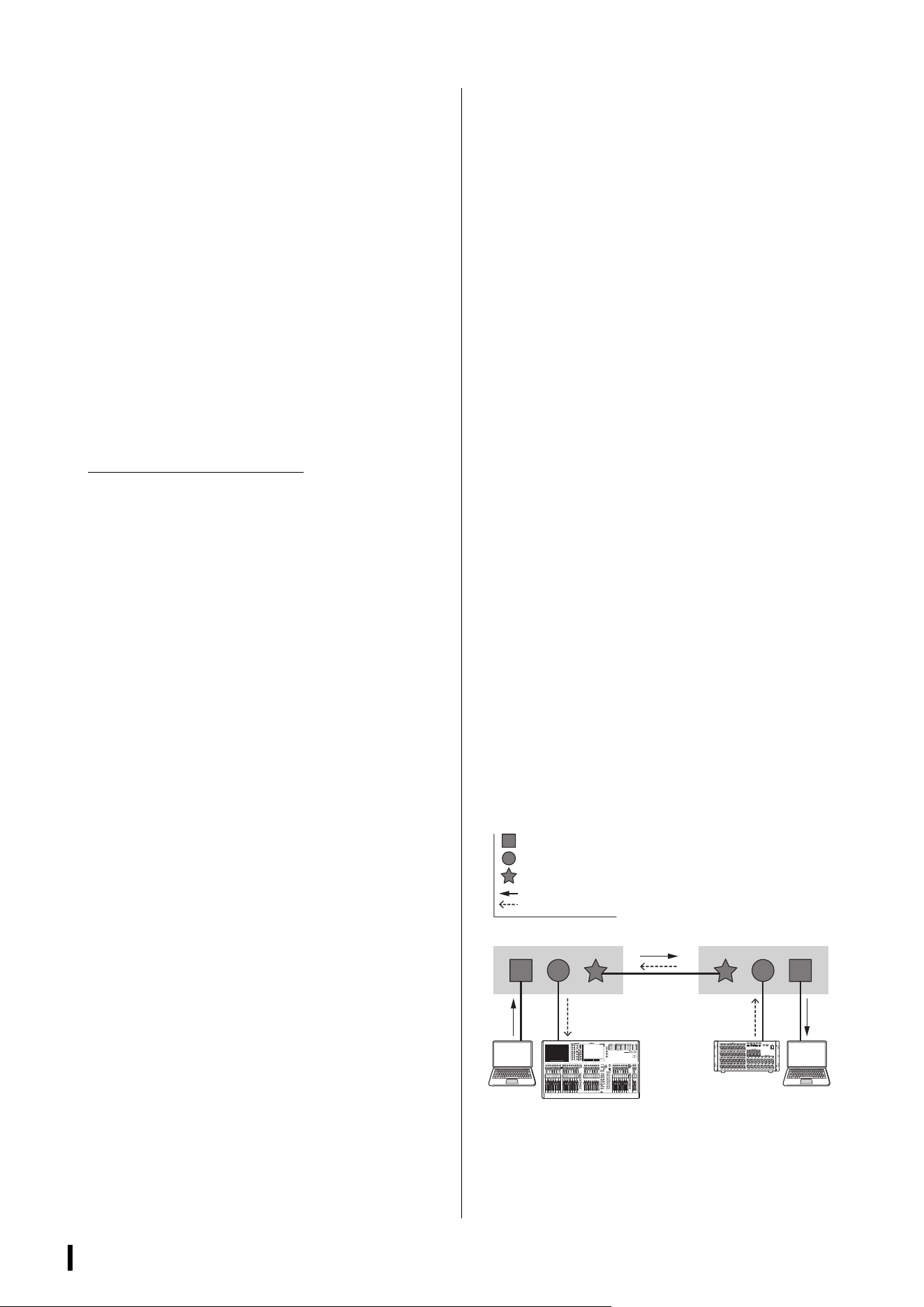
• Trunk
This function adds tags to multiple VLANs so that they
can be transmitted and received via a single
connection. When one SWP2 transmits VLAN 1 data
via the trunk connection, the SWP2 unit that receives
this will transmit the data only to the port that
corresponds to its own VLAN 1.
Communication speed for a metal trunk connection on
the SWP2’s VLAN preset B is 1 Gbps per cable. If
there is only one cable, and the total bandwidth
passing through the trunk connection exceeds
1 Gbps, packets will be delayed or dropped. Some of
the SWP2’s VLAN presets enable link aggregation of
the trunk connection. If the bandwidth will exceed
1 Gbps for a LAN port or 10 Gbps for a 10GBASE-SR/
LR port, or if you want to provide redundancy to guard
against cable breakage, you should use two trunk
cables.
: VLAN 1 port
: VLAN 2 port
: Trunk port
: Data flow
SWP2 Owner’s Manual
11
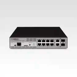
Controls and Functions
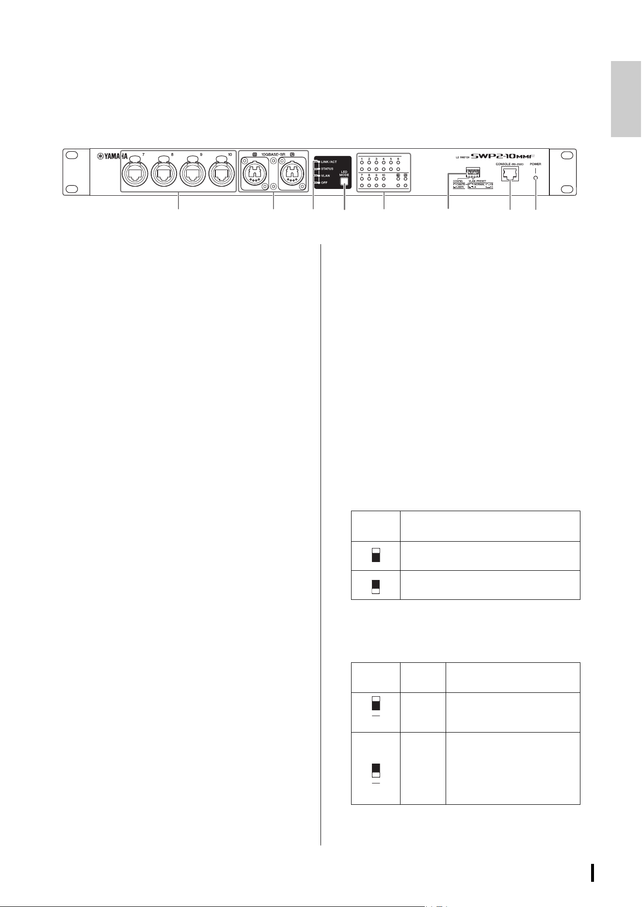
Front panel
The explanation here is based on the SWP2-10MMF.
1 LAN ports
These are etherCON (RJ-45) ports for connecting
Ethernet cables (CAT5e or better is recommended).
A cable with an RJ-45 connector can also be
connected.
All ports support 1000BASE-T, 100BASE-TX, and
10BASE-T.
2 10GBASE-SR ports (SWP2-10MMF)/
10GBASE-LR ports (SWP2-10SMF)
This is an opticalCON DUO port for connecting an
optical fiber cable. LC Duplex connectors can also
be connected.
If you use a cable with an LC Duplex connector,
fasten the dust cap attached to the cable connector
to prevent dust from adhering when the cable is not
in use.
NOTE
• Use an opticalCON DUO optical fiber cable made by
Neutrik Corporation. Since optical fiber cables are
vulnerable to being bent or pulled, you can reduce the
occurrence of problems by using a cable that has a
strong sheath and is equipped with a locking mechanism.
• The SWP2-10MMF can use GI-type multi-mode fiber
cables that have a core diameter of approximately 50 μm
and cladding diameter of approximately 125 μm. The
maximum length between devices is 300 m.
• The SWP2-10SMF can use SM-type single-mode fiber
cables with a core diameter of approximately 9 μm and a
cladding diameter of approximately 125 μm. The
maximum length between devices is 10 km.
• In some cases, the specifications might not be satisfied
because of the optical fiber cables that are used and the
conditions of installation.
• Link up is possible only for 10GBASE-SR/LR between the
same standards. 10GBASE-SR/LR can not link up with
1000BASE optical standards.
Cleaning
Correct communication might not be possible if
debris and/or dust has adhered to the ends of optical
fiber cables or the ports. Clean the equipment
regularly by using commercially available optical
fiber cleaning products.
3 LED mode indicators
This indicates what the status indicators are showing.
4 [LED MODE] button
This switches what the status indicators are showing.
5 Status indicators
These indicate the status of each port. The displayed
content depends on the mode. For details on the
display in each mode, refer to “Status Indicator
Display.”
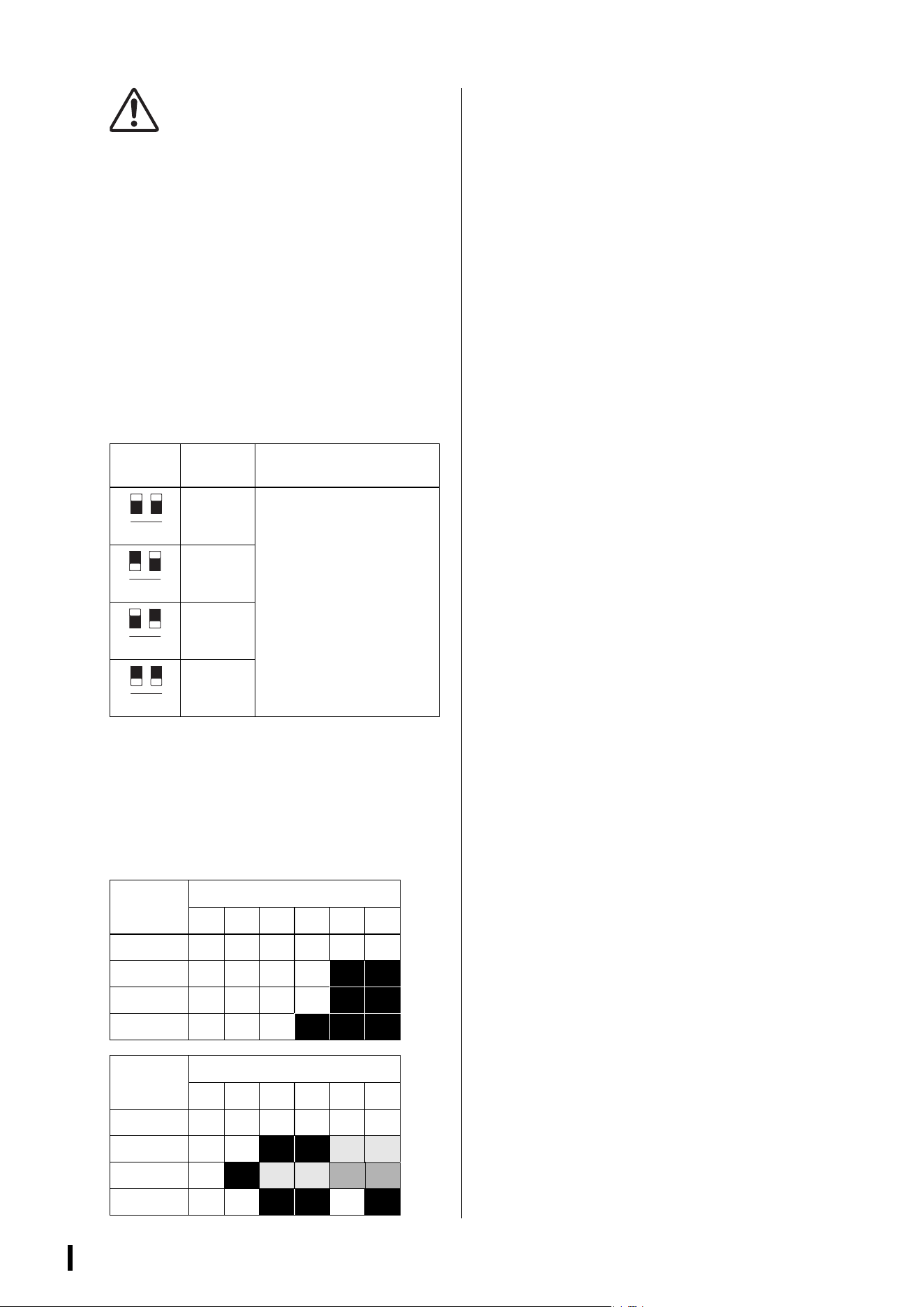
6 DIP switches
These specify startup settings for the unit.
Set the DIP switches when the power is turned off.
The settings are not applied if you change the setting
while the power is on.
The switch illustrations indicate the up/down position
as follows.
• Switch 1 (CONFIG)
Specifies whether the unit’s settings are optimized for
a Dante network or are set by the user.
12345678
Switch
position
Status
Represent a status with switch toggled up.
Represent a status with switch toggled
down.
Switch
position
Option Functions
DANTE
The unit starts up with settings
optimized for a Dante network.
This setting is read only.
USER
The unit starts up with user
settings. This setting can be
read or written; when you
change the setting, the unit
starts up the next time as well
with that setting.
1
1
SWP2 Owner’s Manual
12
Caution when using this unit
together with another
manufacturer’s switch
Dante supports both IGMP V2 and V3, but you must set
all switches in the same network to operate using the
same version.
If the SWP2 starts up with DANTE settings, it operates
using IGMP V3. In this case, if the network includes
even one switch that is operating with IGMP V2,
problems such as dropouts in the sound might occur.
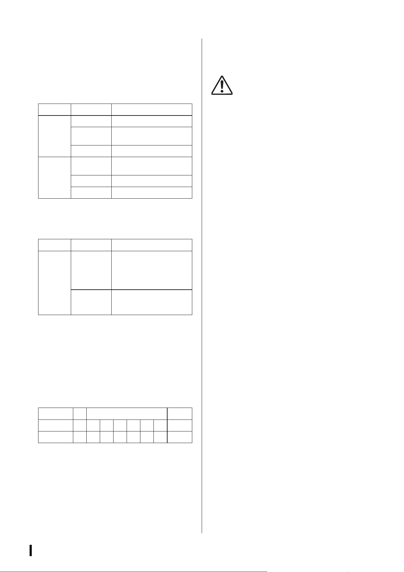
• Switch 2 and 3 (VLAN PRESET)
Specifies the VLAN preset that is used when switch 1
is in the [DANTE] position. This setting is ignored if
switch 1 is set to [USER].
If you change the settings via the web GUI or a
command, the settings are applied temporarily but is
not stored; the next time the unit starts up, it returns
to the VLAN preset setting.
In the tables, “1,” “2,” “Tr1,” and “Tr2” respectively
indicate VLAN 1, VLAN 2, trunk (LAG1), and trunk
(LAG2).
For an explanation of VLAN, trunk, link aggregation,
and LAG, refer to “Terms” on page 10. For details,
you can download technical reference material
(HTML).
(*1) In the VLAN presets, the IGMP Snooping function is
turned on except for VLAN 2 in presets A and B,
preventing multicast communication such as Dante
’s
multicast flow from being forwarded to unnecessary
routes. For this reason, in the case of A or B you
should use the VLAN 1 port for audio signals such as
Dante, and use the VLAN 2 port for control signals.
(*2) If you use setting C, connect the computer that is
using Yamaha Audio Network Monitor to the VLAN 1
port.
7 [CONSOLE (RS-232C)] port
This is an RJ-45 port used to specify commands.
Use an RJ-45/DB-9 console cable to connect this to
the RS-232C port (COM port) of your computer. Use
an RJ-45/DB-9 console cable that is wired as
described in “Specifications.”
8 [POWER] indicator
This is lit when the SWP2 is powered-on.
Switch
position
Option Functions
NORMAL
The following table shows how
the VLAN and trunk are
assigned to ports.
A
B
C
VLAN
PRESET
Rear panel ports
123456
NORMAL 111111
A (*1) 1111
2 2
B (*1) 1111
2 2
C (*2) 111
2 2 2
VLAN
PRESET
Front panel ports
789101112
NORMAL 111111
A (*1) 1 1
2 2 Tr1 Tr1
B (*1) 1
2 Tr1 Tr1 Tr2 Tr2
C (*2) 1 1
2 2 1 2
2 3
2 3
2 3
2 3
SWP2 Owner’s Manual
13
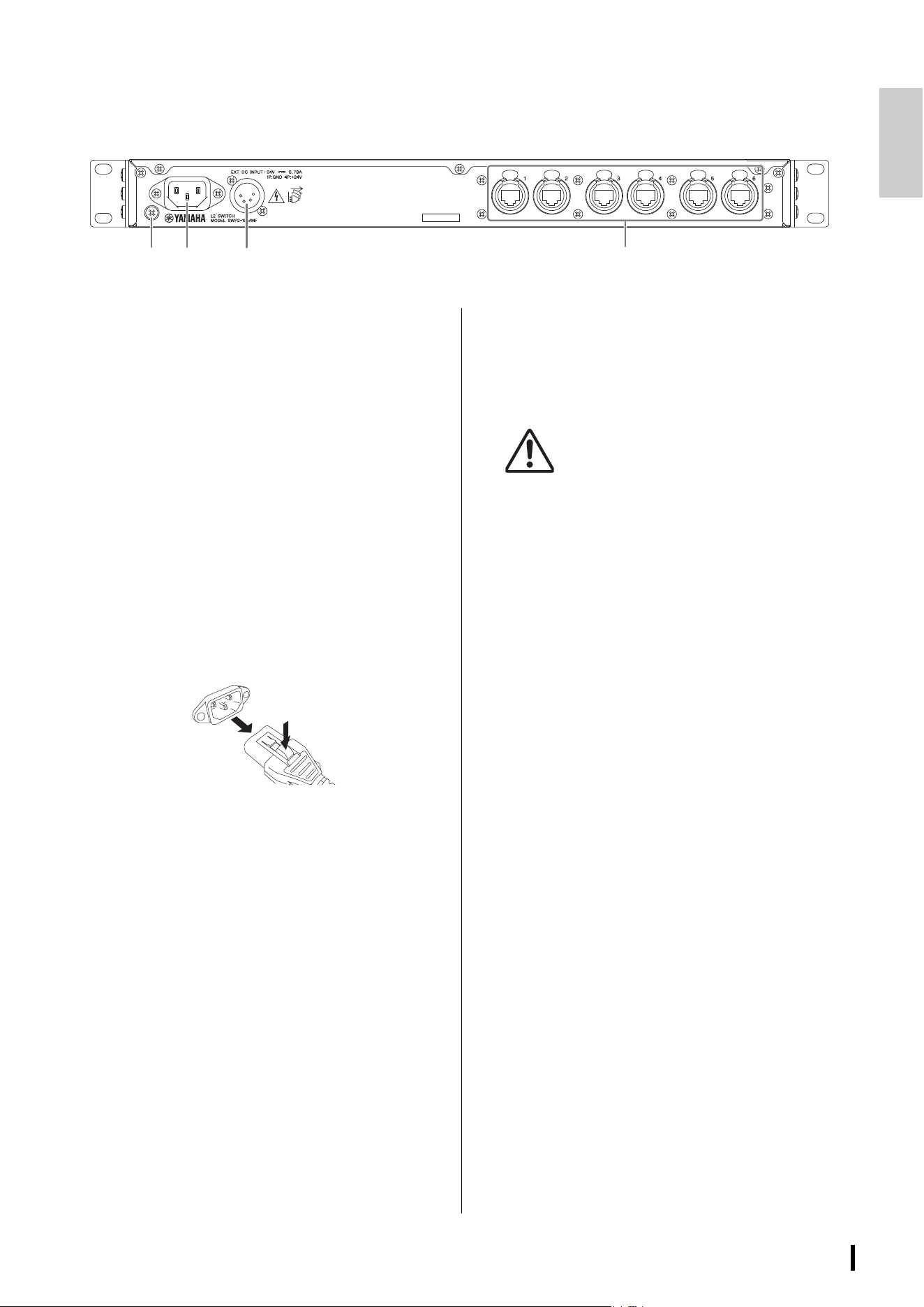
Rear panel
9 Grounding screw
Since the included power cord has a three-pin plug,
this unit will be appropriately grounded if the AC
outlet is grounded. In some cases, you may be able
to reduce hum noise and interference noise by
connecting this screw to ground as well.
) AC IN connector
Connect the included power cord here. First connect
the power cord to this unit, and then connect the
power supply plug to an AC outlet; the SWP2’s
internal power supply turns on.
The supplied AC power cord features a V-lock
mechanism via a latch, which prevents the power
cord from coming off accidentally.
Insert the cable plug all the way until it locks in
securely.
Press the latch button on the plug to disconnect the
power cord.
! [EXT DC INPUT] connector
This is an XLR-4-32 type jack for supplying an
external power supply (+24 V) as a backup for the
SWP2’s internal power supply.
Connect a Yamaha PA-700 AC adaptor or an
equivalent product recommended by Yamaha.
CAUTION
• Before connecting the external power supply, you
must turn off the external power supply. Failing to do
so may cause electrocution or malfunctions.
• EXT DC INPUT connector is intended to be supplied
by Power Supply certified with “Limited Power
Source” or “LPS” and rated 24 Vdc.
NOTE
• If an external power supply is connected, the SWP2 will
operate normally when its internal power supply and the
external power supply are on, as well as when only one is
on.
• If both power supplies are on, and one of them is
interrupted during operation, the unit will continue to
operate normally.
@ LAN ports
These are etherCON (RJ-45) ports for connecting
Ethernet cables (CAT5e or better is recommended).
A cable with an RJ-45 connector can also be
connected.
All ports support 1000BASE-T, 100BASE-TX, and
10BASE-T.
@
9)
!
SWP2 Owner’s Manual
14
Status Indicator Display
If the LED mode is [LINK/ACT]
The status indicators show each port’s link status and
connection status.
If the LED mode is [STATUS]
The status indicators show the loop-related port’s status.
If the LED mode is [VLAN]
The status indicators show the VLAN ID and trunk.
If DIP switch 1 is upward ([DANTE]), VLAN 1 is shown by
the upper indicator and the lower indicator unlit. VLAN 2
is shown by the upper indicator lit green and the lower
indicator unlit. Trunk is shown by upper and lower
indicators lit orange.
–: Unlit, G: Lit green, O: Lit orange
NOTE
• If a number of VLANs that cannot be completely displayed
above is specified, the upper and lower indicators are lit
green.
• If multiple VLAN IDs are specified for the same port, the
upper and lower indicators are lit orange.
If the LED mode is [OFF]
All status indicators are unlit.
SWP2 Initialization
Settings can be reinitialized to factory default settings by
the following three methods.
CAUTION
Do not switch off the SWP2 during initialization. Doing so
could cause a product failure.
NOTICE
• Settings cannot be reinitialized if the administrative
password is still the default setting. Use Web GUI or
command operations to change the administrative
password.
• All communications are temporarily disabled immediately
after reinitialization.
NOTE
• The Web GUI can also be used to export current settings
before they are reinitialized. For more details, refer to
“Technical Data.”
• If reinitialization fails, have the unit inspected by the dealer
that sold the unit or by contacting the Yamaha customer
service support center.
Using the Web GUI to restore
factory settings
1. Log in to the Web GUI via the Yamaha LAN
Monitor.
2. Click the [Management] tab
[Maintenance] [Restart and initialize], in
that order.
The “Restart and initialize” screen is displayed.
3. In the “Initialize” section, click the [Next]
button.
The “Initialize” screen is displayed.
4. Enter the administrative password and
then click the [OK] button.
The “Check executed content” screen is
displayed.
5. Check the settings and then click the
[Execute] button.
The settings are restored to factory settings and
the SWP2 unit is restarted.
Indicator Illumination Status
Upper
Lit green Link is established. (LINK)
Flashing
green
Data is being transferred.
(ACT)
Unlit Link is lost.
Lower
Lit green
Connected with 1000BASE-T
or 10GBASE-SR/LR.
Lit orange Connected with 100BASE-TX.
Unlit Connected with 10BASE-T.
Indicator Illumination Status
Upper
and lower
Flashing
orange
Loop was detected and
communication was halted, or
an abnormality in the
opticalCON light reception
level was detected.
Unlit
Loop not detected. Or loop
was detected, but
communication is not halted.
Indicators
1
VLAN ID low high
Trunk
Upper – GO – – GO O
Lower – – – G O O G O
SWP2 Owner’s Manual
15
Using commands to restore
factory settings
Factory settings can be restored using the [CONSOLE]
port or a Telnet or SSH client. The following describes
how to restore factory settings via the [CONSOLE] port.
Preparing the computer
Terminal software is required for controlling the computer
serial (COM) port. Before starting, configure the terminal
software parameter settings as indicated below.
1. Connect an RJ-45/DB-9 console cable
between the computer and SWP2 unit.
2. Turn on the power to the SWP2 unit.
A startup message is displayed on the computer
console screen.
3. Press the <Enter> key.
The software will wait for the user name to be
entered.
4. Enter the user name and press the <Enter>
key.
The software will wait for the password to be
entered.
5. Enter the password and press the <Enter>
key.
A command prompt will appear when the
password is successfully authenticated.
6. Enter “enable” and press the <Enter> key.
That will enable EXEC mode privileges.
7. Enter “cold start” and press the <Enter>
key.
The software will wait for the administrative
password to be entered.
8. Enter the administrative password and
press the <Enter> key.
The settings are restored to factory settings and
the SWP2 unit is restarted.
Pressing the <I> key during
startup to restore factory
settings
Factory settings can be restored by pressing the
uppercase <I> key during SWP2 startup.
Make sure the terminal software parameter settings are
already configured as indicated in “Using commands to
restore factory settings” above.
1. Connect an RJ-45/DB-9 console cable
between the computer and SWP2 unit.
2. Unplug the SWP2 power cord and plug it
back in.
That restarts the SWP2 unit.
NOTE
The following steps are the same even if the SWP2 unit
was restarted using command operations.
3. Within one second after “BootROM Ver.”
appears on the computer console screen,
press the uppercase <I> key.
The initialization confirmation screen is displayed.
4. Press the <y> key.
The settings are restored to factory settings and
the SWP2 unit is restarted.
Parameter Value
Data transmission speed 9600 bps
Character bit length 8
Parity check None
Number of stop bits 1
Flow control Xon/Xoff
SWP2 Owner’s Manual
16
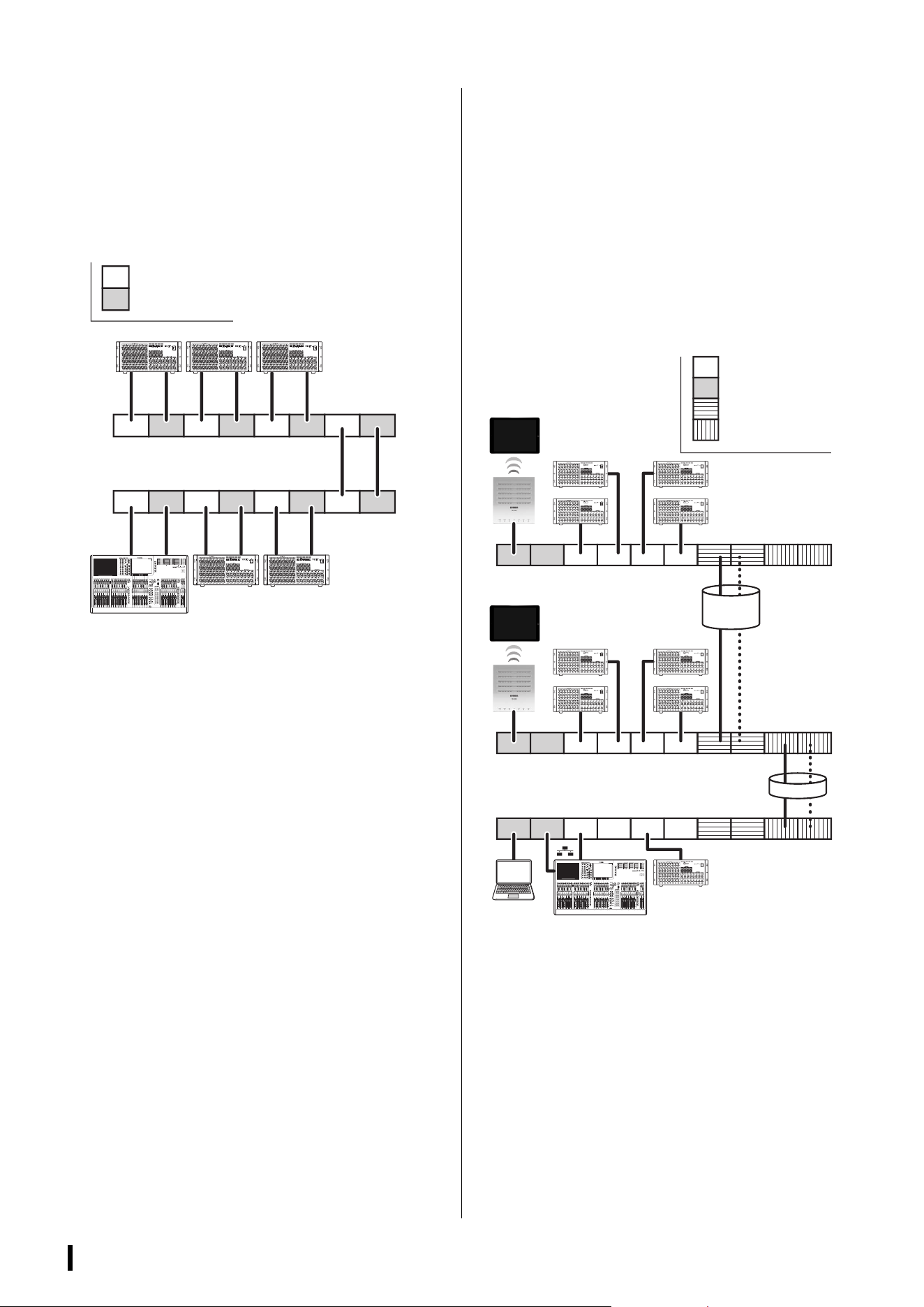
VLAN Use Cases
Redundant Dante connections
This case double the cables between devices as a
safeguard against cable breakage. This diagram shows
a setup using VLAN preset C.
Separating control signals
from audio signals
This case logically separates control signals such as for
Editor or StageMix from Dante’s audio signals, making
the network more stable. This diagram shows a setup
using VLAN preset B.
If VLANs are not used, and control signals and audio
signals flow across the same network, the two will
compete for communication bandwidth. In order to
prevent such an effect, we recommend that you use
VLANs to separate the control signal and audio signal
networks.
PSPSPS
PS PSPS
PS
VLAN 1 (Primary)
VLAN 2 (Secondary)
SWP2
(VLAN
preset
= C)
SWP2
(VLAN
preset
= C)
StageMix
StageMix
VLAN 1 (Audio)
VLAN 2 (Control)
Trunk (LAG1)
Trunk (LAG2)
SWP2
(VLAN preset = B)
SWP2
(VLAN preset = B)
SWP2
(VLAN preset = B)
Editor

SWP2 Owner’s Manual
17
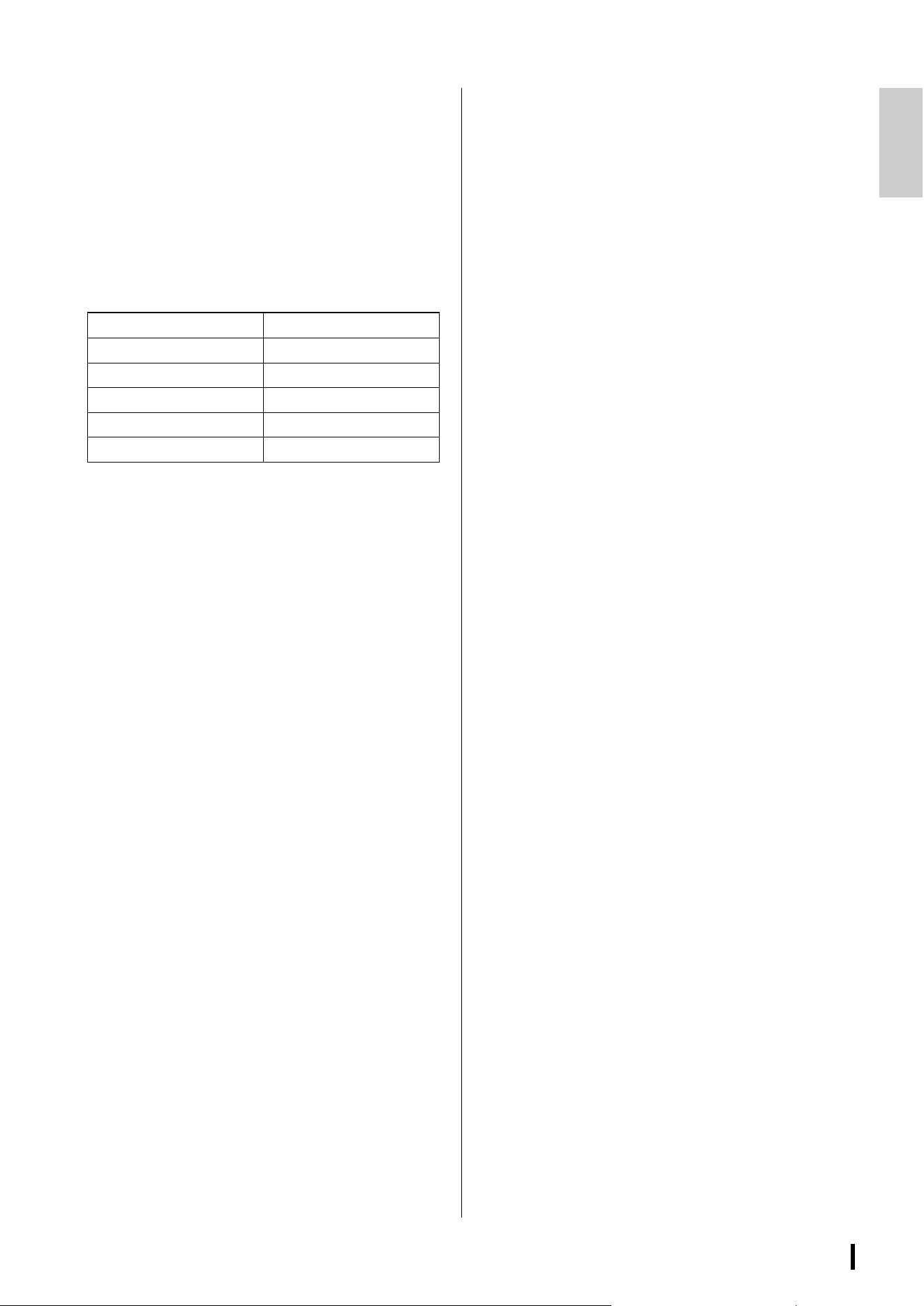
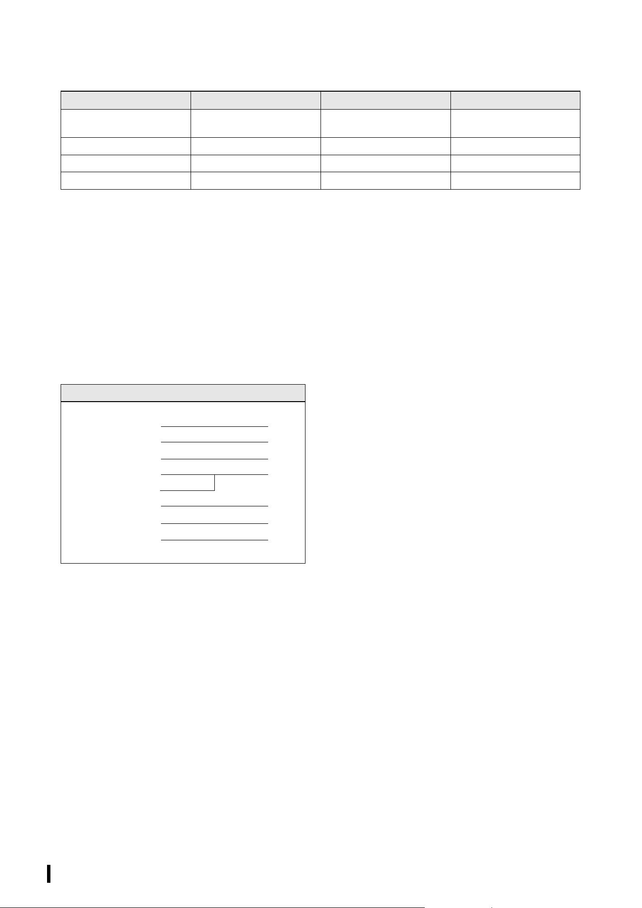
Specifications
General specifications
*1 The LED MODE button allows the PORT indicators to be switched between indicating LINK/ACT-SPEED, STATUS, or VLAN.
Parameter SWP2-10MMF SWP2-10SMF
Number of LAN ports
(1000BASE-T/100BASE-TX/10BASE-T,
etherCON connector)
10
Number of SFP+ ports
(10GBASE-SR, opticalCON DUO connector)
20
Number of SFP+ ports
(10GBASE-LR, opticalCON DUO connector)
02
Console port 1 (RJ-45)
Automatic negotiation Available
Auto MDI/MDI-X Available
DIP switches CONFIG, VLAN PRESET
Indicators (Front) POWER, LED MODE × 4
PORT × 10 × 2
*1
, SFP+ × 2 × 2
Operating temperature range 0 to 40°C
Storage temperature range −20 to 60°C
Power supply (AC IN inlet) AC100 V – 240 V, 50/60 Hz, Internal power supply (no power switch)
Power supply inlet: locking type
Power supply (EXT DC INPUT inlet) 24 VDC±2 V, 0.78 A, XLR-4-32 type Connector
Maximum power consumption
(Wattage, Current)
21 W, 0.35 A
Heat dissipation 18.5 kcal/h
Body material Metal case, no fan
Hazardous substances management RoHS compliant
Dimensions (W x H x D) 480 × 44 × 362 mm (18-7/8" × 1-3/4" × 14-1/4")
Weight (excluding accessories) 4.5 kg (9.9 lbs)
Accessories Power cord, Owner’s manual
Option item PA-700 (AC adaptor)
SWP2 Owner’s Manual
18
Interface specifications
*1 These terminals support AutoMDI/MDI-X
*2 Conforming cable: SWP2-10MMF: GI-type multi-mode fiber cables with a core diameter /cladding diameter of approximately 50 μm/
125 μm. Maximum cable length: 300 m
SWP2-10SMF: SM-type single-mode fiber cables with a core diameter /cladding diameter of approximately 9 μm/
125 μm. Maximum cable length: 10 km
*3 10GBASE-SR: SWP2-10MMF, 10GBASE-LR: SWP2-10SMF
*4 For the pin assignments, refer to “Connector pin assignments”
*5 Pin 4=+24 VDC, pin 1=GND, pins 2 and 3=N.C.
External power supply requirements: 24 VDC±2 V, 0.78 A
Connector pin assignments
CONSOLE (RS-232C)
* These signals are not used on the SWP2.
Terminal Format Level Connector
1-10
*1
IEEE802.3 10BASE-T/100BASE-TX/
1000BASE-T
etherCON CAT5e
11, 12
*2
IEEE802.3ae 10GBASE-SR 10GBASE-LR
*3
opticalCON
CONSOLE (RS-232C) – RS-232C RJ-45
*4
EXT DC INPUT – – XLR-4-32 type
*5
Signal RJ45 D-SUB 9
9
RTS 1 8
DTR 2 6
TxD 3 2
GND 4 5
GND 5
RxD 6 3
DSR* 7 4
CTS* 8 7
1
SWP2 Owner’s Manual
19
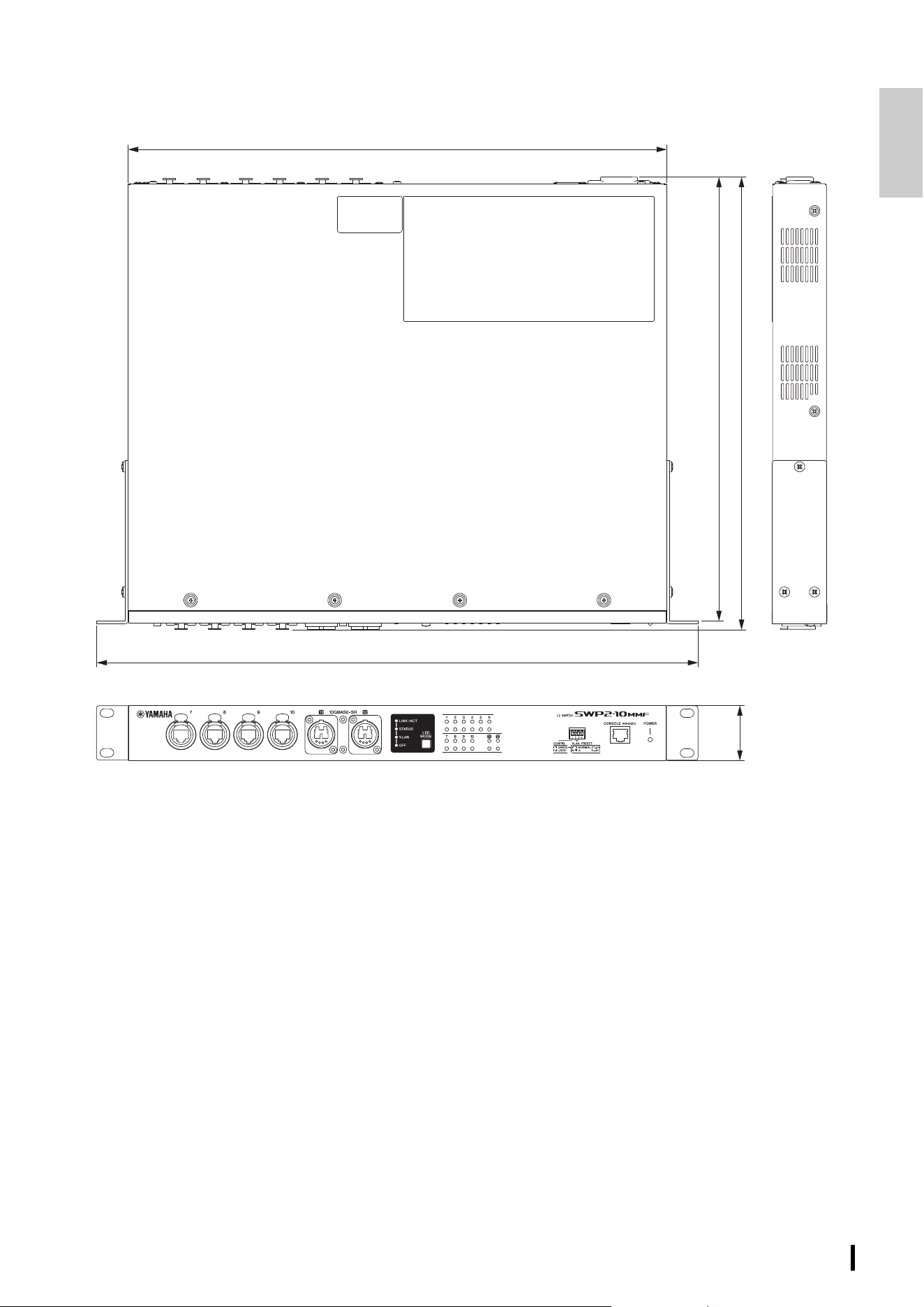
Dimensions
* The contents of this manual apply to the specifications as of the firmware Rev. 2.03.15. To obtain the latest manual, access the Yamaha
website then download the manual file.
480
362
355
430
44
Unit: mm

For detailed guarantee information about this Yamaha product, and Pan-EEA* and Switzerland warranty service, please either visit the website address below (Printable file is available
at our website) or contact the Yamaha representative office for your country. * EEA: European Economic Area
Important Notice: Guarantee Information for customers in EEA* and Switzerland
English
Für nähere Garantie-Information über dieses Produkt von Yamaha, sowie über den Pan-EWR*- und Schweizer Garantieservice, besuchen Sie bitte entweder die folgend angegebene Internetadresse
(eine druckfähige Version befindet sich auch auf unserer Webseite), oder wenden Sie sich an den für Ihr Land zuständigen Yamaha-Vertrieb. *EWR: Europäischer Wirtschaftsraum
Wichtiger Hinweis: Garantie-Information für Kunden in der EWR* und der Schweiz
Deutsch
Pour des informations plus détaillées sur la garantie de ce produit Yamaha et sur le service de garantie applicable dans l’ensemble de l’EEE ainsi qu’en Suisse, consultez notre site Web
à l’adresse ci-dessous (le fichier imprimable est disponible sur notre site Web) ou contactez directement Yamaha dans votre pays de résidence. * EEE : Espace Economique Européen
Remarque importante: informations de garantie pour les clients de l’EEE et la Suisse
Français
Voor gedetailleerde garantie-informatie over dit Yamaha-product en de garantieservice in heel de EER* en Zwitserland, gaat u naar de onderstaande website (u vind een afdrukbaar
bestand op onze website) of neemt u contact op met de vertegenwoordiging van Yamaha in uw land. * EER: Europese Economische Ruimte
Belangrijke mededeling: Garantie-informatie voor klanten in de EER* en Zwitserland
Nederlands
Para una información detallada sobre este producto Yamaha y sobre el soporte de garantía en la zona EEE* y Suiza, visite la dirección web que se incluye más abajo (la version del
archivo para imprimir esta disponible en nuestro sitio web) o póngase en contacto con el representante de Yamaha en su país. * EEE: Espacio Económico Europeo
Aviso importante: información sobre la garantía para los clientes del EEE* y Suiza
Español
Per informazioni dettagliate sulla garanzia relativa a questo prodotto Yamaha e l’assistenza in garanzia nei paesi EEA* e in Svizzera, potete consultare il sito Web all’indirizzo riportato
di seguito (è disponibile il file in formato stampabile) oppure contattare l’ufficio di rappresentanza locale della Yamaha. * EEA: Area Economica Europea
Avviso importante: informazioni sulla garanzia per i clienti residenti nell’EEA* e in Svizzera
Italiano
Para obter uma informação pormenorizada sobre este produto da Yamaha e sobre o serviço de garantia na AEE* e na Suíça, visite o site a seguir (o arquivo para impressão está
disponível no nosso site) ou entre em contato com o escritório de representação da Yamaha no seu país. * AEE: Área Econômica Européia
Aviso importante: informações sobre as garantias para clientes da AEE* e da Suíça
Português
īȚĮȜİʌIJȠȝİȡİȓȢ ʌȜȘȡȠijȠȡȓİȢİȖȖȪȘıȘȢ ıȤİIJȚțȐȝİ IJȠʌĮȡȩȞ ʌȡȠȧȩȞIJȘȢ <DPDKDțĮȚ IJȘȞțȐȜȣȥȘ İȖȖȪȘıȘȢıİ ȩȜİȢIJȚȢ ȤȫȡİȢIJȠȣ ǼȅȋțĮȚIJȘȞǼȜȕİIJȓĮİʌȚıțİijIJİȓIJİIJȘȞʌĮȡĮțȐIJȦ
ȚıIJȠıİȜȓįĮǼțIJȣʌȫıȚȝȘȝȠȡijȒİȓȞĮȚįȚĮșȑıȚȝȘıIJȘȞȚıIJȠıİȜȓįĮȝĮȢȒĮʌİȣșȣȞșİȓIJİıIJȘȞĮȞIJȚʌȡȠıȦʌİȓĮIJȘȢ<DPDKDıIJȘȤȫȡĮıĮȢǼȅȋǼȣȡȦʌĮȧțȩȢȅȚțȠȞȠȝȚțȩȢȋȫȡȠȢ
ȈȘȝĮȞIJȚțȒıȘȝİȓȦıȘȆȜȘȡȠijȠȡȓİȢİȖȖȪȘıȘȢȖȚĮIJȠȣȢʌİȜȐIJİȢıIJȠȞǼȅȋțĮȚǼȜȕİIJȓĮ
ǼȜȜȘȞȚțȐ
För detaljerad information om denna Yamahaprodukt samt garantiservice i hela EES-området* och Schweiz kan du antingen besöka nedanstående webbaddress (en utskriftsvänlig fil
finns på webbplatsen) eller kontakta Yamahas officiella representant i ditt land. * EES: Europeiska Ekonomiska Samarbetsområdet
Viktigt: Garantiinformation för kunder i EES-området* och Schweiz
Svenska
Detaljert garantiinformasjon om dette Yamaha-produktet og garantiservice for hele EØS-området* og Sveits kan fås enten ved å besøke nettadressen nedenfor (utskriftsversjon finnes
på våre nettsider) eller kontakte kontakte Yamaha-kontoret i landet der du bor. *EØS: Det europeiske økonomiske samarbeidsområdet
Viktig merknad: Garantiinformasjon for kunder i EØS* og Sveits
Norsk
De kan finde detaljerede garantioplysninger om dette Yamaha-produkt og den fælles garantiserviceordning for EØO* (og Schweiz) ved at besøge det websted, der er angivet nedenfor (der
findes en fil, som kan udskrives, på vores websted), eller ved at kontakte Yamahas nationale repræsentationskontor i det land, hvor De bor. * EØO: Det Europæiske Økonomiske Område
Vigtig oplysning: Garantioplysninger til kunder i EØO* og Schweiz
Dansk
Tämän Yamaha-tuotteen sekä ETA-alueen ja Sveitsin takuuta koskevat yksityiskohtaiset tiedot saatte alla olevasta nettiosoitteesta. (Tulostettava tiedosto saatavissa sivustollamme.)
Voitte myös ottaa yhteyttä paikalliseen Yamaha-edustajaan. *ETA: Euroopan talousalue
Tärkeä ilmoitus: Takuutiedot Euroopan talousalueen (ETA)* ja Sveitsin asiakkaille
Suomi
$E\GRZLHG]LHüVLĊZLĊFHMQDWHPDWZDUXQNyZJZDUDQF\MQ\FKWHJRSURGXNWXILUP\<DPDKDLVHUZLVXJZDUDQF\MQHJRZFDá\P(2*L6]ZDMFDULLQDOHĪ\RGZLHG]LüZVND]DQąSRQLĪHMVWURQĊLQWHUQHWRZą
3OLNJRWRZ\GRZ\GUXNX]QDMGXMHVLĊQDQDV]HMVWURQLHLQWHUQHWRZHMOXEVNRQWDNWRZDüVLĊ]SU]HGVWDZLFLHOVWZHPILUP\<DPDKDZVZRLPNUDMX(2*²(XURSHMVNL2EV]DU*RVSRGDUF]\
WDĪQHWDUXQNLJZDUDQF\MQHRERZLą]XMąFHZ(2*L6]ZDMFDULL
Polski
3RGUREQp]iUXþQtLQIRUPDFHRWRPWRSURGXNWX<DPDKDD]iUXþQtPVHUYLVXYFHOpP(+6DYHâYêFDUVNXQDOH]QHWHQDQtåHXYHGHQpZHERYpDGUHVHVRXERUNWLVNXMHGRVWXSQêQDQDãLFK
ZHERYêFKVWUiQNiFKQHERVHPĤåHWHREUiWLWQD]DVWRXSHQtILUP\<DPDKDYHVYp]HPL(+6(YURSVNêKRVSRGiĜVNêSURVWRU
'ĤOHåLWpR]QiPHQt=iUXþQtLQIRUPDFHSUR]iND]QtN\Y(+6DYHâYêFDUVNX
ýHVN\
$MHOHQ<DPDKDWHUPpNUHYRQDWNR]yUpV]OHWHVJDUDQFLDLQIRUPiFLyNYDODPLQWD](*7UHpV6YiMFUDNLWHUMHGĘJDUDQFLiOLVV]ROJiOWDWiVWHNLQWHWpEHQNHUHVVHIHOZHEKHO\QNHWD]DOiEEL
FtPHQDZHEKHO\HQQ\RPWDWKDWyIiMOWLVWDOiOYDJ\SHGLJOpSMHQNDSFVRODWEDD]RUV]iJiEDQPĦN|GĘ<DPDKDNpSYLVHOHWLLURGiYDO(*7(XUySDL*D]GDViJL7pUVpJ
)RQWRVILJ\HOPH]WHWpV*DUDQFLDLQIRUPiFLyND](*7WHUOHWpQpV6YiMFEDQpOĘYiViUOyNV]iPiUD
Magyar
7lSVHPDWHDEHVDDPLVHNVVHOOH<DPDKDWRRWHJDUDQWLLQLQJNRJX(XURRSD0DMDQGXVSLLUNRQQDMDâYHLWVLJDUDQWLLWHHQLQGXVHNRKWDNODVWDJHSDOXQYHHELVDLWLDOOMlUJQHYDODDGUHVVLOPHLH
saidil on saadaval prinditav fail) või pöörduge Teie regiooni Yamaha esinduse poole. * EMP: Euroopa Majanduspiirkond
2OXOLQHPlUNXV*DUDQWLLWHDYH(XURRSD0DMDQGXVSLLUNRQQD(03MDâYHLWVLNOLHQWLGHOH
Eesti keel
/DLVDƼHPWXGHWDOL]ƝWXJDUDQWLMDVLQIRUPƗFLMXSDUãR<DPDKDSURGXNWXNƗDUƯJDUDQWLMDVDSNDOSRãDQX((=XQâYHLFƝOnjG]XDSPHNOƝMLHW]HPƗNQRUƗGƯWRWƯPHNƺDYLHWQHVDGUHVLWƯPHNƺD
YLHWQƝLUSLHHMDPVGUXNƗMDPVIDLOVYDLVD]LQLHWLHVDUMnjVXYDOVWLDSNDOSRMRãR<DPDKDSƗUVWƗYQLHFƯEX((=(LURSDV(NRQRPLNDV]RQD
6YDUƯJVSD]LƼRMXPVJDUDQWLMDVLQIRUPƗFLMDNOLHQWLHP((=XQâYHLFƝ
Latviešu
-HLUHLNLD LãVDPLRVLQIRUPDFLMRV DSLHãƳ Ä<DPDKD³SURGXNWą LUMR WHFKQLQĊSULHåLnjUą YLVRMH((( LUâYHLFDULMRMH DSVLODQN\NLWHPnjVǐ VYHWDLQơMHWROLDX QXURG\WXDGUHVX VYHWDLQơMH\UD
VSDXVGLQWLQDVIDLODVDUEDNUHLSNLWơVƳÄ<DPDKD³DWVWRY\EĊVDYRãDOLDL(((±(XURSRVHNRQRPLQơHUGYơ
'ơPHVLRLQIRUPDFLMDGơOJDUDQWLMRVSLUNơMDPV(((LUâYHLFDULMRMH
/LHWXYLǐNDOED
3RGUREQpLQIRUPiFLHR]iUXNHWêNDM~FHVDWRKWRSURGXNWXRGVSRORþQRVWL<DPDKDDJDUDQþQRPVHUYLVHY(+3DâYDMþLDUVNXQiMGHWHQDZHERYHMVWUiQNHXYHGHQHMQLåãLHQDQDãHM
ZHERYHMVWUiQNHMHNGLVSR]tFLLV~ERUQDWODþDOHERVDREUiĢWHQD]iVWXSFXVSRORþQRVWL<DPDKDYRVYRMHMNUDMLQH(+3(XUySVN\KRVSRGiUVN\SULHVWRU
'{OHåLWpXSR]RUQHQLH,QIRUPiFLHR]iUXNHSUH]iND]QtNRYY(+3DâYDMþLDUVNX
6ORYHQþLQD
=DSRGUREQHMãHLQIRUPDFLMHRWHP<DPDKLQHPL]GHONXWHUJDUDQFLMVNHPVHUYLVXYFHORWQHP(*3LQâYLFLRELãþLWHVSOHWQRPHVWRNLMHQDYHGHQRVSRGDMQDWLVOMLYDGDWRWHNDMHQDYROMRQD
QDãHPVSOHWQHPPHVWXDOLVHREUQLWHQD<DPDKLQHJDSUHGVWDYQLNDYVYRMLGUåDYL(*3(YURSVNLJRVSRGDUVNLSURVWRU
3RPHPEQRREYHVWLOR,QIRUPDFLMHRJDUDQFLML]DNXSFHY(*3LQâYLFL
6ORYHQãþLQD
Ɂɚɩɨɞɪɨɛɧɚɢɧɮɨɪɦɚɰɢɹɡɚɝɚɪɚɧɰɢɹɬɚɡɚɬɨɡɢɩɪɨɞɭɤɬɧɚ<DPDKDɢɝɚɪɚɧɰɢɨɧɧɨɬɨɨɛɫɥɭɠɜɚɧɟɜɩɚɧɟɜɪɨɩɟɣɫɤɚɬɚɡɨɧɚɧɚȿɂɉɢɒɜɟɣɰɚɪɢɹɢɥɢɩɨɫɟɬɟɬɟɩɨɫɨɱɟɧɢɹɩɨɞɨɥɭɭɟɛ
ɫɚɣɬɧɚɧɚɲɢɹɭɟɛɫɚɣɬɢɦɚɮɚɣɥɡɚɩɟɱɚɬɢɥɢɫɟɫɜɴɪɠɟɬɟɫɩɪɟɞɫɬɚɜɢɬɟɥɧɢɹɨɮɢɫɧɚ<DPDKDɜɴɜɜɚɲɚɬɚɫɬɪɚɧɚȿɂɉȿɜɪɨɩɟɣɫɤɨɢɤɨɧɨɦɢɱɟɫɤɨɩɪɨɫɬɪɚɧɫɬɜɨ
ȼɚɠɧɨɫɴɨɛɳɟɧɢɟɂɧɮɨɪɦɚɰɢɹɡɚɝɚɪɚɧɰɢɹɬɚɡɚɤɥɢɟɧɬɢɜȿɂɉɢɒɜɟɣɰɚɪɢɹ
Ȼɴɥɝɚɪɫɤɢɟɡɢɤ
3HQWUXLQIRUPDĠLLGHWDOLDWHSULYLQGDFHVWSURGXV<DPDKDúLVHUYLFLXOGHJDUDQĠLH3DQ6((úL(OYHĠLDYL]LWDĠLVLWHXOODDGUHVDGHPDLMRVILúLHUXOLPSULPDELOHVWHGLVSRQLELOSHVLWHXOQRVWUX
VDXFRQWDFWDĠLELURXOUHSUH]HQWDQĠHL<DPDKDGLQĠDUDGXPQHDYRDVWUă6((6SDĠLXO(FRQRPLF(XURSHDQ
1RWLILFDUHLPSRUWDQWă,QIRUPDĠLLGHVSUHJDUDQĠLHSHQWUXFOLHQĠLLGLQ6((úL(OYHĠLD
/LPEDURPkQă
=DGHWDOMQHLQIRUPDFLMHRMDPVWYX]DRYDM<DPDKLQSURL]YRGWHMDPVWYHQRPVHUYLVX]DFLMHOL(*3LâYLFDUVNXPROLPR9DVGDSRVMHWLWHZHEVWUDQLFXQDYHGHQXXQDVWDYNXLOLNRQWDNWLUDWH
RYODãWHQRJ<DPDKLQRJGREDYOMDþDXVYRMRM]HPOML(*3(XURSVNLJRVSRGDUVNLSURVWRU
9DåQDREDYLMHVW,QIRUPDFLMHRMDPVWYX]DGUåDYH(*3DLâYLFDUVNH
Hrvatski
https://europe.yamaha.com/warranty/
URL_5
Important Notice: Guarantee Information for customers in European
Economic Area (EEA) and Switzerland

Published 06/2023 MWES-B0
© 2019 Yamaha Corporation
VGC8720
Yamaha Downloads
https://download.yamaha.com/
Yamaha Pro Audio global website
https://www.yamahaproaudio.com/