
!
USER MANUAL
IP CAMERA
IPC-R-UM-REV07062021
R-series

User Manual
OVERVIEW! 2 .........................................................................................................................................................
Product Description! 2 ..........................................................................................................................................
Technology! 2 ......................................................................................................................................................
Glossary & Defaults! 2 .........................................................................................................................................
IP CAMERA ACCESS! 3 ...........................................................................................................................................
CAMIUS TOOLS! 4 ..................................................................................................................................................
Overview! 4 ........................................................................................................................................................
Device Config Tool! 4 ...........................................................................................................................................
Password & Preview! 5 .........................................................................................................................................
PLAYBACK! 9 ..........................................................................................................................................................
REMOTE SETTING! 10 .............................................................................................................................................
1. Channel! 10 .....................................................................................................................................................
1.1 Live! 10 ......................................................................................................................................................
1.2 Image Control! 10 ......................................................................................................................................
1.3 Video Cover! 12 .........................................................................................................................................
2. Record! 13 ......................................................................................................................................................
2.1 Encode! 13 ................................................................................................................................................
2.2 Record! 14 .................................................................................................................................................
3. Event! 14 .........................................................................................................................................................
3.1 Setup! 14 ...................................................................................................................................................
3.2 Alarm! 17 ..................................................................................................................................................
4. AI! 19 .............................................................................................................................................................
5. Network! 20 ....................................................................................................................................................
5.1 General! 20 ...............................................................................................................................................
5.2 Email! 22 ...................................................................................................................................................
5.3 FTP! 23 ......................................................................................................................................................
5.4 RTSP! 23 ...................................................................................................................................................
5.5 DDNS! 24 .................................................................................................................................................
5.6 HTTPS! 24 ..................................................................................................................................................
5.7 IP Filter! 25 ................................................................................................................................................
6. Device! 26 .......................................................................................................................................................
6.1 Disk! 26 .....................................................................................................................................................
6.2 Audio Setting! 26 .......................................................................................................................................
6.3 Cloud! 27 ..................................................................................................................................................
7. System! 28 .......................................................................................................................................................
7.1 General! 28 ...............................................................................................................................................
7.2 Multi-user! 29 .............................................................................................................................................
7.3 Maintenance! 30 ........................................................................................................................................
7.4 Information! 33 ..........................................................................................................................................
CAMIUS VIEW! 35..................................................................................................................................................
1

User Manual
————————————————————————————————————————————————
OVERVIEW
Product Description
This user manual is applicable to the latest R-series of Camius IP cameras (BoltX5R, Iris5R, Spot8R,
Spot8RS). The list of the IP camera models covered by this user manual will be kept updated periodically.
Camius IP cameras are digital online surveillance cameras embedded with a Web server and capable of
independent operation, giving user access to real-time monitoring through a web browser or surveillance
software from any location.
Camius IP cameras comply with H.264/ H.265 / H.264+ / H.265+ / MJPEG high profile encoding standards.
Authorized remote users can gain access to real-time monitoring using the IP address or hostname or P2P
ID of the IP camera. Camius IP cameras are easy to install and operate.
Remote management allows different authorization levels for users.
The IP camera can be set to detect various events like an object moving in view of the camera or sound
picked up by the built-in microphone and then send an alert to the owner’s smartphone or a snapshot to
their Email address.
Technology
A high-performance single SOC chip is used as the media processor for audio/video acquisition,
compression and transmission/transfer. Standard H.264/ H.265 / H.264+ / H.265+ / MJPEG encoding
algorithms are applied to ensure clear and smooth video representation and transfer performance.
Embedded Web Server offers users access to real-time surveillance and remote control of front-end
camera.
Glossary & Defaults
•
IP camera or IPC or Device refers to the network camera!
•
The default factory IP address for IP camera is 192.168.1.168 unless DHCP is enabled on the
network; in which case the IP camera will be assigned an IP address by the gateway (router), and if
the IP camera was paired with a PoE NVR then it’ll be assigned an IP like 10.10.25.151 and in this
case the NVR manages access to the camera.
•
The default factory administrator username for IP camera is admin (in lowercase), the IP camera
will require the user to setup a password on first browser access, there’s no need to set a password
for a direct PoE connection with the Camius NVR.
•
The default Web port number is 80 and the default media (client) port number is 9988.
•
•
If the IP camera has a hard reset button, you can use it to reset the camera’s password and
settings.
Please note,!in case any of the information in this manual didn’t apply to the product please reach out to us
and we’ll make sure you get the updated information by submitting a support ticket using the following
link:!https://camius.com/support
This manual may change without prior notice as we’re constantly working on developing our products.
2
User Manual
————————————————————————————————————————————————
IP CAMERA ACCESS
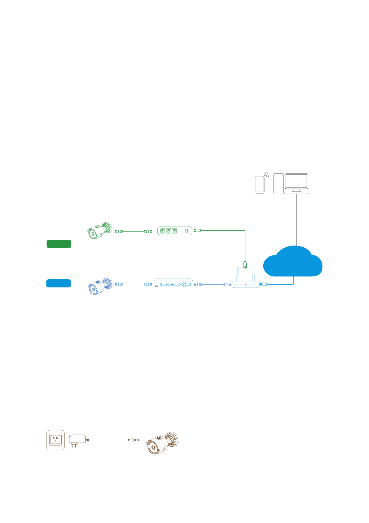
Camius IP cameras can be powered up in one of three methods:
1. (Mode 1) By connecting it into the PoE port on your Camius NVR (Recommended).
2. (Mode 2) By connecting it to a PoE switch or a PoE injector on your network
3. (Mode 3) Using a 12VDC 1-2A power supply
To verify that your IP camera is powered up:
-
Physical check: The Infrared LEDs around the lens illuminate faint red light in the dark while the camera is
on.
-
Search Using the Device Config tool on your PC or Mac.
-
Search Using the VMS Software on your PC or Mac.
-
Search using the Camius View App on your smartphone or tablet.
For direct access to your IP Camera configuration, make sure the camera is powered using Mode 2.
If a PoE switch or a PoE injector is not used, you can power the camera using mode 3:
Plug a UL-listed 12VDC-2AMP power supply into the DC plug on the camera wire, and make sure the
ethernet cable is used between the IP camera and the router or a switch on your local network.
Mode 2 and Mode 3 will allow the user to access the camera directly, giving access to its native settings
using the VMS software or Internet Explorer.
While Mode 1 (direct connection to the PoE on your NVR) will list the camera under the NVRs interface and
camera management can only be done on the NVR.
In order to configure audio on your Camius IP camera
Make sure your IP camera is connected using Mode 2 or 3; navigate to Setup / Device / Audio for audio
settings.
!
PoE IP Camera
Power+Data Out
PoE Port WAN LAN
Router
PoE Switch or
PoE Injector
PC / MacSmartphone
Or Tablet
PoE IP Camera PoE NVR
Mode 1
Mode 2
Internet
Mode 3: Direct DC power
3
User Manual
————————————————————————————————————————————————
CAMIUS TOOLS
Overview
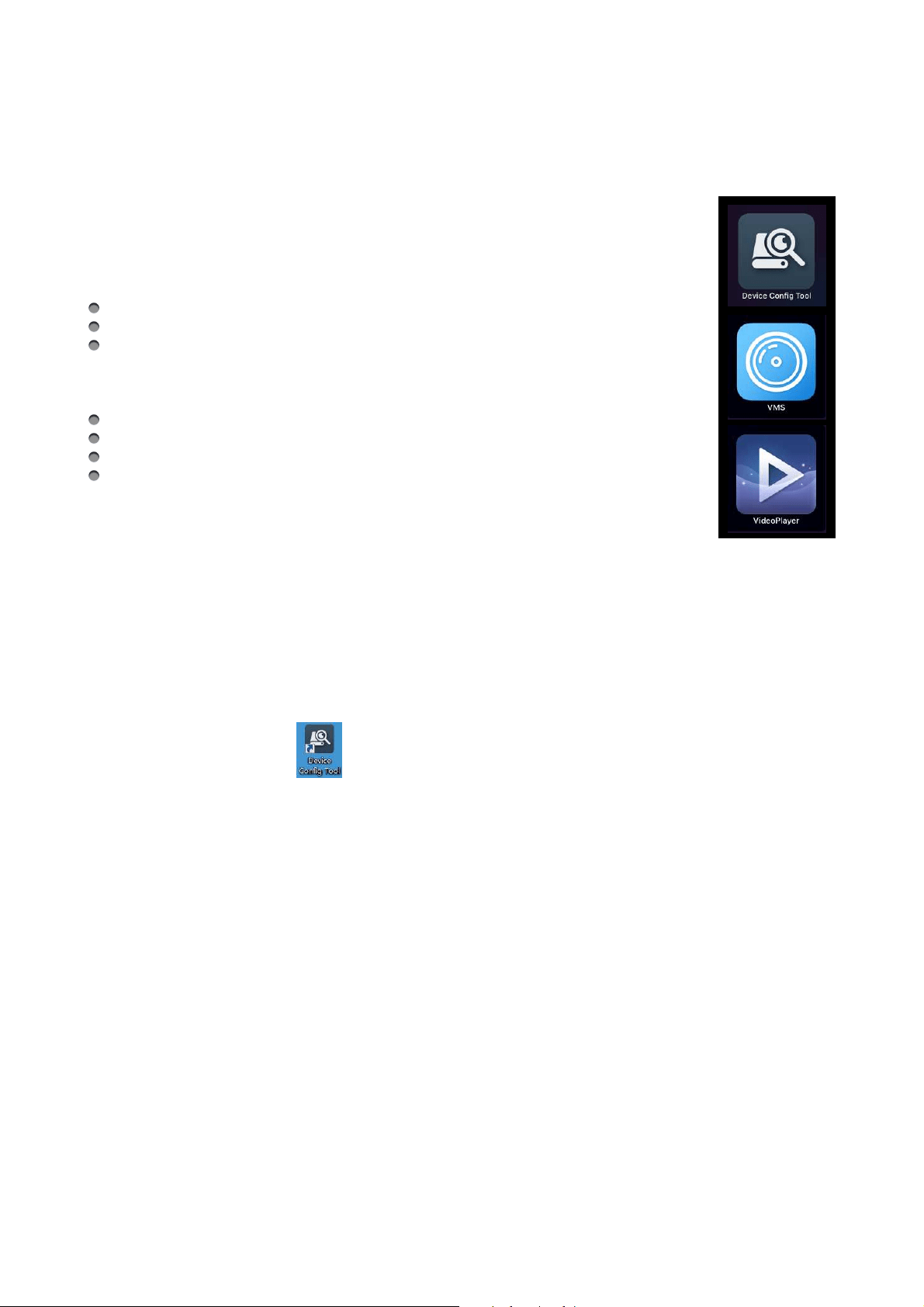
Camius offers tools and software to expand the scope of your smart security system.
Device Config tool!is a lightweight Camius device scanner and configuration tool, usage
scope is as follows:
Find and connect your Camius devices to your PC on your local network LAN
Change your Camius devices network settings
Upgrade Firmware on your Camius devices
Camius VMS Software!turns your PC or Mac into a surveillance station; VMS stands for
Video Management System, with it you can:
Group all of your Camius devices and view them, even from a remote location
Access Device Configuration and change settings
Record locally onto a disk attached to your computer
Playback video and audio, locally and remotely.
"
Video Player Software!plays video/audio files backed up from your recorder on your PC
or Mac. The user has the option to back up footage from the recorder in MP4 or Camius
proprietary format.
Using Video Player, the user can take clear screenshots, trim critical parts of the video file, and play
multiple files simultaneously.
Device Config Tool
Download Device Config Tool from https://camius.com/support and install it on your PC or Mac.
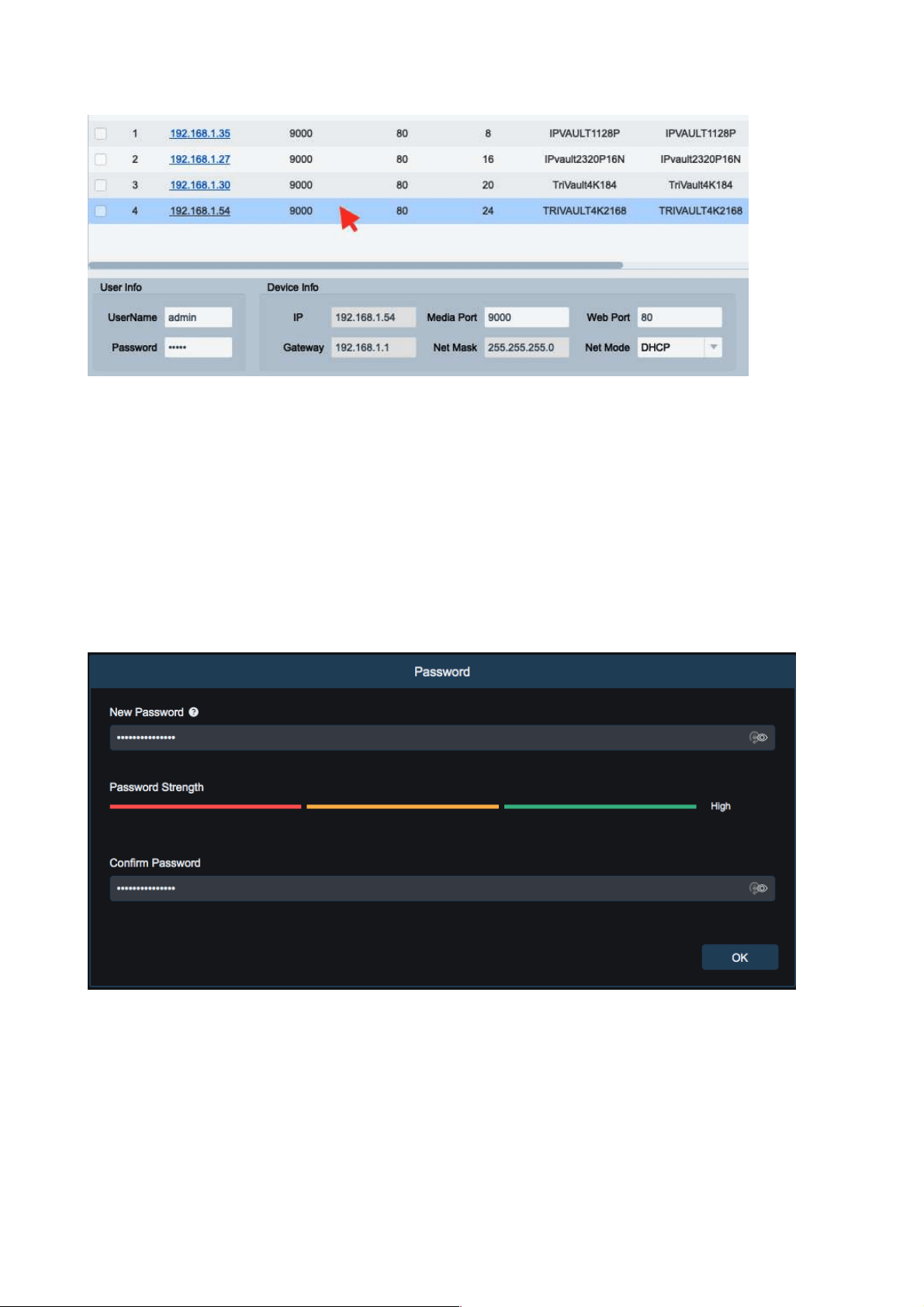
Click on the Search button to find any Camius device connected to your local network.
The search tab allows you to update network settings on your device as follows:
Click to highlight a device.
Choose a Net Mode: DHCP or Static.
To manually adjust network settings, type in the new IP, Gateway, Net Mask, and Media Port.
Type in the password you set for the device earlier and click Modify. Click the search button again in 10
seconds to verify changes.
Browser access
On PC/Mac, click on the IP address of a device or type its IP address in your web browser (IE8,9,10,11,
Chrome 44/lower, Firefox 51/lower, Safari 11/lower).!
4
User Manual
!
About Firmware Upgrade: This tool allows Camius IP cameras firmware upgrade. Please select the IP
camera you wish to upgrade in the left frame. Open the icon to choose the firmware you want, put in the
user name and password, then click the Upgrade button.
Password & Preview
Once you launched your web browser and enter the IP address of the camera (http://192.168.1.168) or
accessed it using the Device Config Tool, for the 1st time access, you’d need to set a password (8 to 15
characters).
!
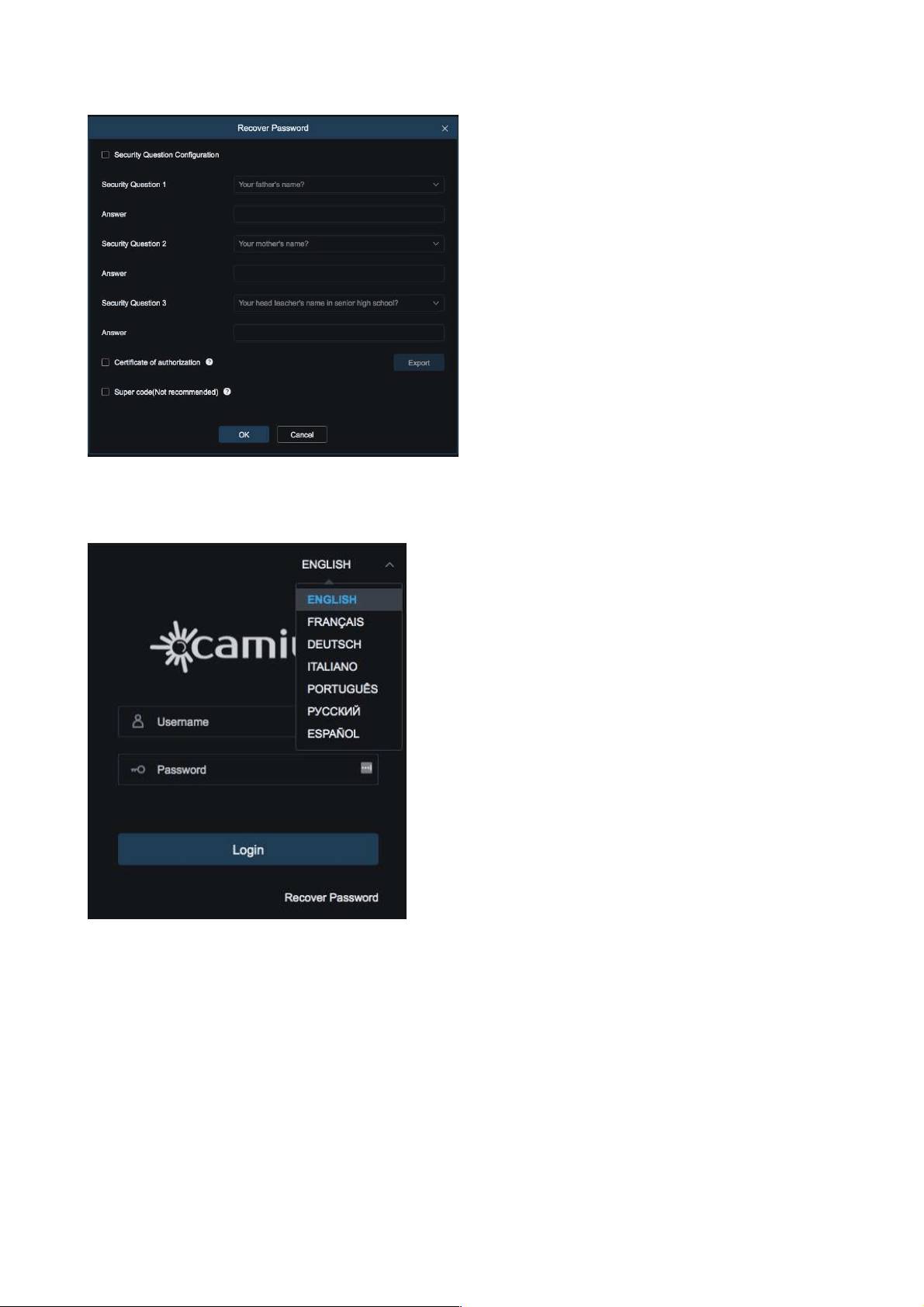
• You will have an option to check a box ‘Security Question Configuration“ if you wish to enable a
‘Recover Password’ function as shown below. If you don’t check the box, the ‘Recover Password
function will be doable and you can contact Camius Support at Camius.com/support for assistance!
5
User Manual
!
• You can also select the preferred language in the same login window.
• If you enable Recover Password feature, just click on the Recover Password button on the right bottom of
the window and it will take you to the security questions.
!
6
User Manual
!
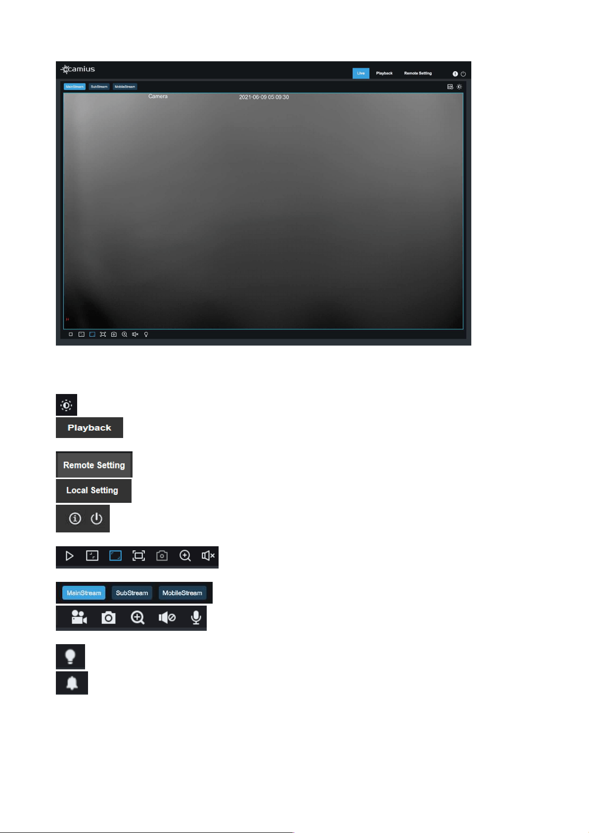
Once you successfully set your device password and logged in, you will see your device Live stream.
The preview window has the following functions:
To set color of the frame (hue, brightness, contrast, saturation, and sharpness)
View the IP camera recording stored to an SD card, playback the footage in the web
browser
Access to device menu to customized settings
For a setting of the snapshot, video file type, and storage path
Information about current user, web browser / Logout button
Play the video file / Original proportions / Stretch / Full Screen /
Capture (Take a snapshot) / Digital Zoom / Audio Volume
Select the device stream
Control buttons: Open Video, Snapshot, Zoom In/Out, Sound On/Off,
Microphone
Enable / Disable Warning Light
Enable / Disable Siren
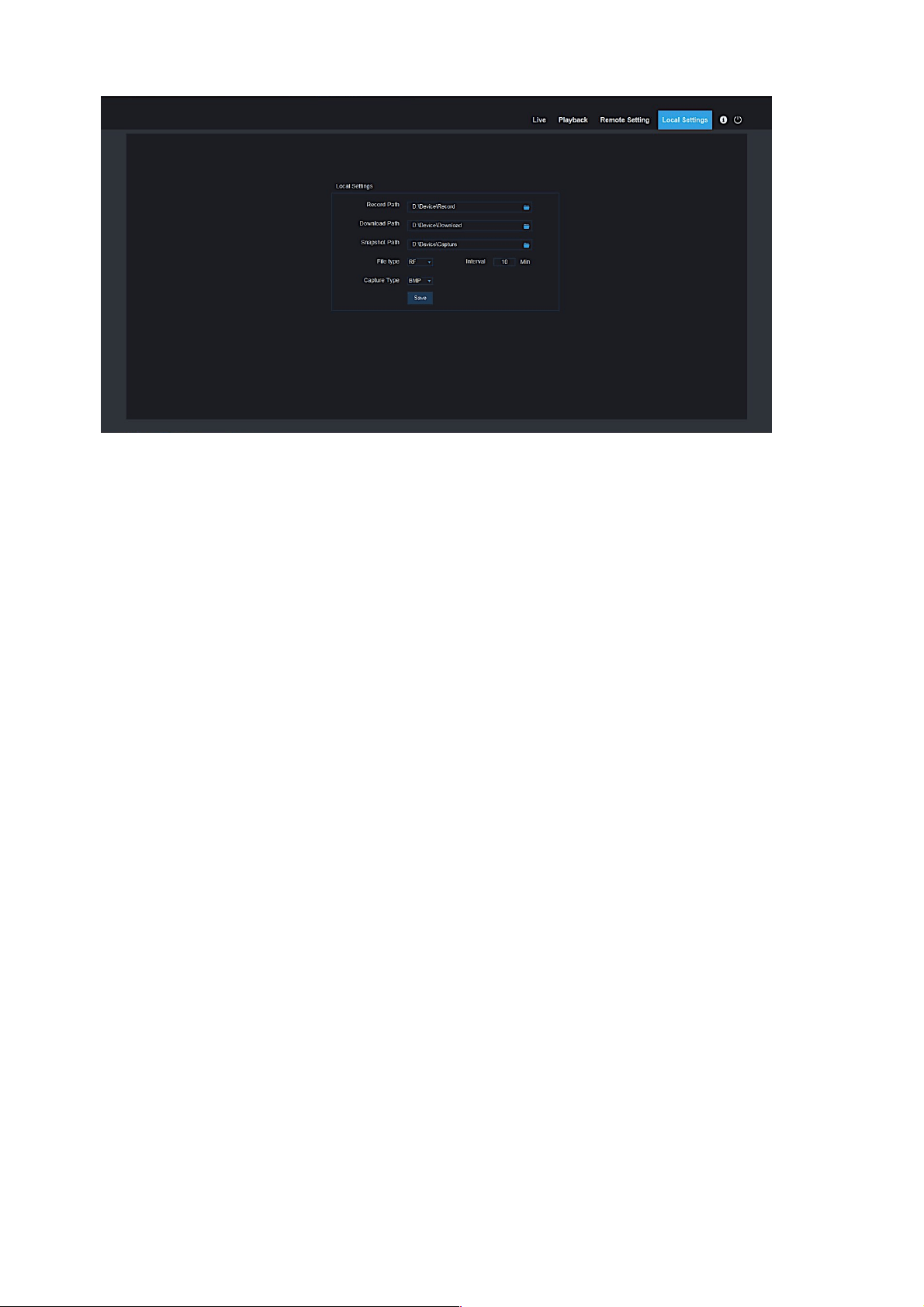
Note: Local Settings is an optional feature and comes only with certain Camius devices. If you need
this feature, please contact us at camius.com/contact prior to a purchase
7
User Manual
Click Path Configuration button to pop up the following dialog box: In this dialog box, you can set
video storage location, paths for download of remote file and storage of image snapshot, file type (RF
by default, in H265 encoding) and video recording duration.
8
User Manual
————————————————————————————————————————————————
PLAYBACK
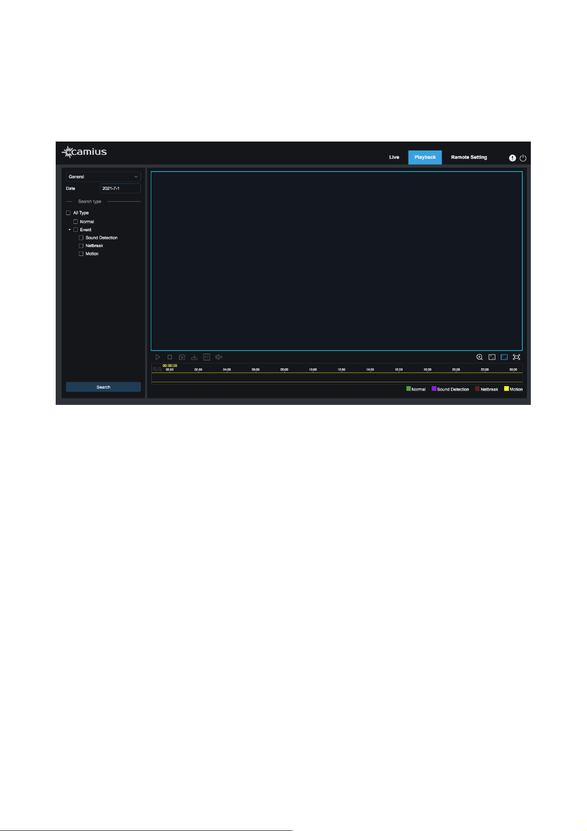
This function comes with only supported devices (IP cameras with onboard SD storage). Click the recorded
file to playback, select the corresponding date, then click the Search to go to the below page.
!
Users can search video by file type and operate the video using a simple toolbar that allows Play/Stop the
video, Bitstream, Record, Capture a snapshot, Download recording, Quick Motion Video playback, and turn
the Sound On/Off. Also, users can use a Digital Zoom, change screen view to Original Proportions, Stretch,
or Full Screen.
9
User Manual
————————————————————————————————————————————————
REMOTE SETTING
1. Channel
In this section you can view the device live, configure the device image control settings, setup the camera\s
video cover, region of interest.
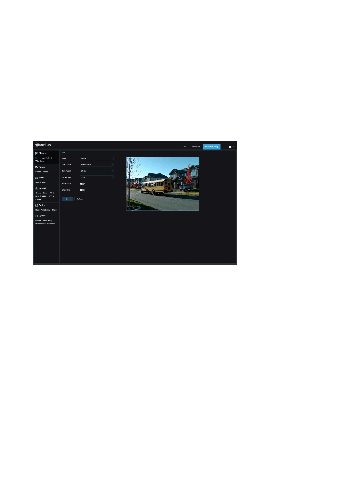
1.1 Live
The device live preview allows you to set the device name, date & time format, select flicker control
between 50Hz & 60Hz, show name and time on the preview screen.
1.2 Image Control
Camius professional IP cameras allow users to tweak each setting of the camera. Users can adjust and
modify multiple parameters to enhance the image and get the best results using its features.
10

User Manual
!
IR-CUT Mode
Infrared!Cut-off filter supports selecting one of 4 modes to improve visibility according to
environment illumination condition:
- Automatic (when the camera automatically switches between color & black white mode)
- Color
- Black White
- Schedule (according to preset schedule to switch mode)
IR-CUT Delay
select value to delay Infrared!Cut-off filter switch in seconds
IR-LED
Manual / SmartIR
Low Beam Light
(optional, with
only supported
devices)
Adjustable levels (it is an optional feature which comes only with supported models such as
SPOT8R, SPOT8RS, etc)
Angle Trad
Select value between 0 or 180 degrees
Mirror
Disable / Vertical / Horizontal / All
Black Light
Disable / DWDR or WDR / HLC / Back Light
• Enable WDR or D-WDR to balance extremely dark and bright lighting conditions to get a better
image.
• HLC [Highlight Compensation] helps to detect bright light spots reducing brightness to improve
overall images
Note: WDR, HLC are available only in certain devices.
WDR coefficient
Adjustable level 0 to 255, available only for supported models only
HLC Strength
Adjustable level 0 to 255, available only for devices with HLC feature
White Balance
Select between Automatic or Manual to adjust color balance to capture a true color image
Shutter
Set it to Automatic or Manual to get a better image of moving and static objects
Time Exposure
Select value between 1/5 (or 1/30 for selected device models) to 1/20000 or select “Flickerless’ to
control the amount of light allowed to fall on the camera’s image sensor. Shorter speed is to
capture moving objects, longer speed - for static objects
11

User Manual
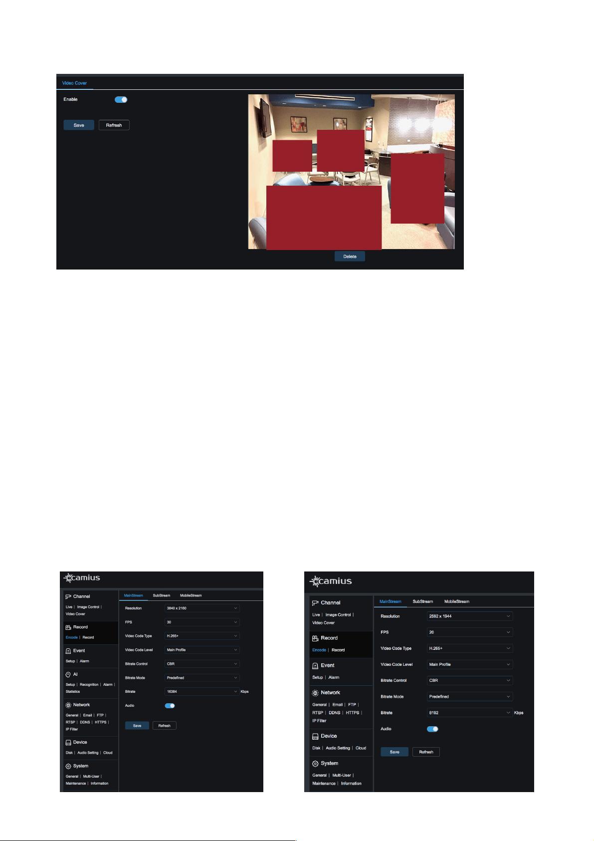
1.3 Video Cover
Use this feature to block out a portion of the camera image for privacy. You can configure up to 4 privacy
areas.
To set a privacy area first tab ‘Enable’ and by! pressing down and holding the left mouse button and drag
out an area for video blocking (up to four areas at one time). Then, click ‘Save’ to enable the video blocking
area.!
Delete:!After clicking Refresh, choose a blocked area by clicking it, then click ‘Delete,’ then ‘Save’ to delete
the privacy area.!
Defog
OFF / Automatic / Manual (Use this feature to get a clearer image when the camera is working
under foggy weather conditions)
3D Noise
Reduction
Automatic / OFF (this feature is used to remove noises from the image in low light conditions more
effectively)
12
User Manual
!
2. Record
In this section, users can select the device resolution encoding settings in different streams, enable
recording, set recording schedule.
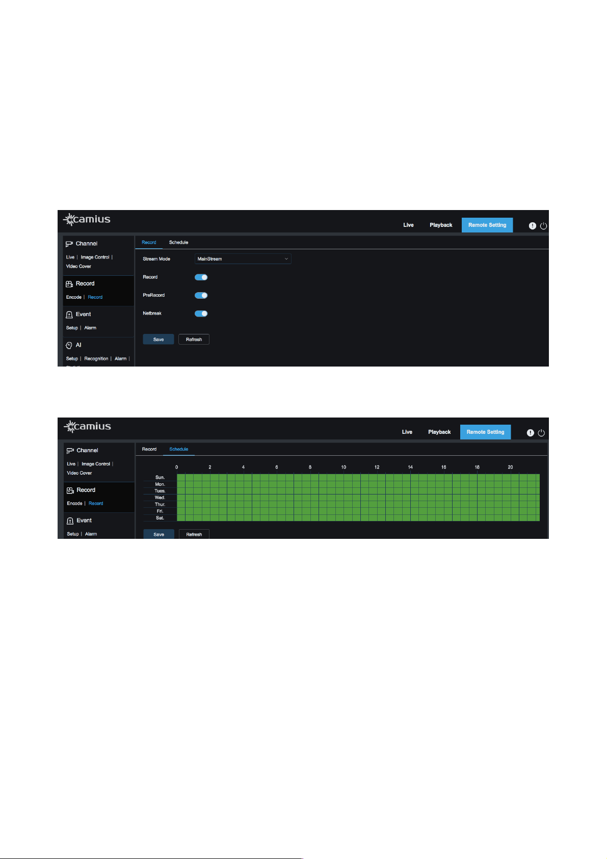
2.1 Encode
This function is to control the device settings in each stream: MainStream, SubStream or MobileStream.
User can configure the video resolution.
• FPS (frames per second): select value between 0 to 30 (depends on the device, stream, video resolution)
• Video code type: H.264, H.264+, H.265, H.265+. SubStream supports MJPEG video codec. More
• Video Code Level: Main Profile / High profile / Baseline
• Bitrate Control: CBR or VBR
• Bitrate Mode: Predefined or User-defined
• Bitrate: Select value between 256 to 8192 or 16384 kbps (kilobyte per second) [values depend on the
device model]
• iFrame Interval: select value between 1 to 80 or 120 [values depend on the device model and selected
stream]
• Audio: if you wish to include Audio in the select encoding settings, enable it
13
This picture is used on the example of Spot8R IP camera.
This picture is used on the example of Iris5R IP camera.
User Manual
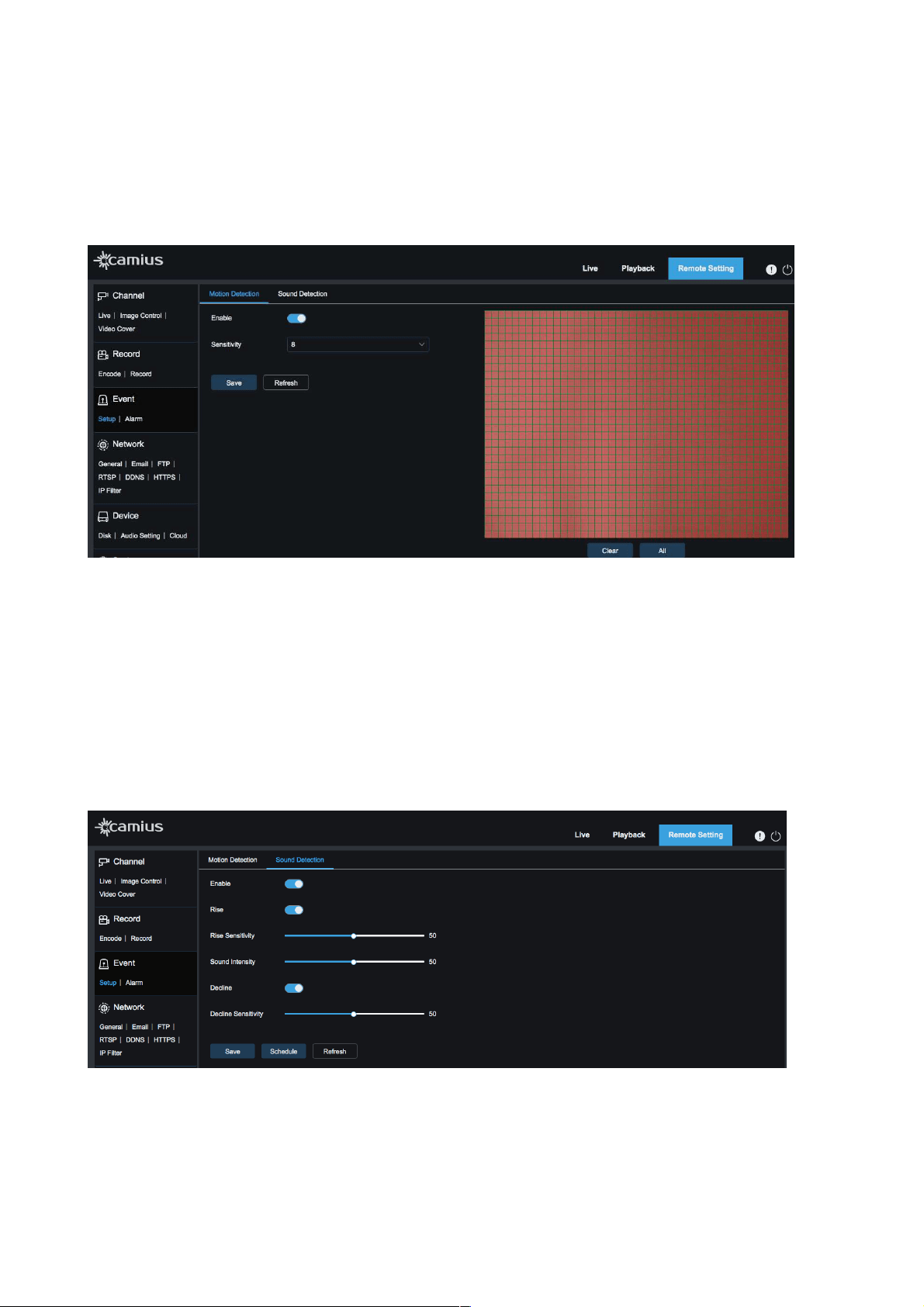
2.2 Record
Select a stream mode between MainStream or Substream, in which you wish to record your device
• Record: Enable it if you wish your device to record
• Pre-record: enable it if you want the device to record 5 seconds before an event occurs, that reduces the
chance of an event not being!recorded.
• Netbreak: When the IP camera is disconnected from the network and only connected to the power
supply, it will automatically record to the camera's onboard SD card (this option is available to the IP
cameras which have an SD storage slot). Click on ‘Netbreak’ toggle to activate move if you wish to
enable it.
!
Tab ‘Schedule’ to select Recording Schedule. Once you selected your schedule, click ‘Save’. One grid in
the table is 30 minutes. Users can customize recording schedule according to their needs.
!
3. Event
3.1 Setup
MOTION DETECTION
Motion Detection [Video Motion Detection] is used to save valuable time while searching for an event or
incident in playback. It allows users to set detection areas under setup for IP cameras, a schedule is
available for detection hours and days. Video motion detection triggers recording and other actions on your
device.
You can set motion recording as the only recording method to save on disk space [SD card or the HDD of
the NVR, if the camera is connected to it] or activate motion recording along with normal 24/7 recording to
record everything while having easy access to video footage triggered by motion.
14
User Manual
1. Check Enable button.
2. Set the sensitivity level between 1 to 8 for motion (higher value indicates higher sensitivity)
3. Click on ‘Save’
4. If you wish to set a specific area of the view to detect Motion, hold your left mouse button and drag out
an area you target.
(Note: When an object moves within the target area, a letter "M" in green color will be displayed on the
preview frame)
SOUND DETECTION
This feature applies only to those IP cameras which support audio function [with a built-in microphone or a
wired audio input to add an external microphone]. Using this feature takes advantage of the onboard
microphone to trigger Alerts and Recording Events based on noise occurring near the camera. It is helpful
if the lens didn't cover the noise source at the time of the event.
1. Click 'Enable' to activate Sound Detection.
2. If you enable the 'Rise' or 'Decline' buttons, the IP camera will trigger alerts or record when the
Sound arises or declines. When you allow these criteria, you will be able to adjust the sensitivity
levels as well.
!
PIR
The “PIR” feature applies only to those IP cameras which are equipped with a built-in PIR sensor. Passive
Infrared or PIR is a better way to detect motion; it is used as an alarm system to detect human movement.
15
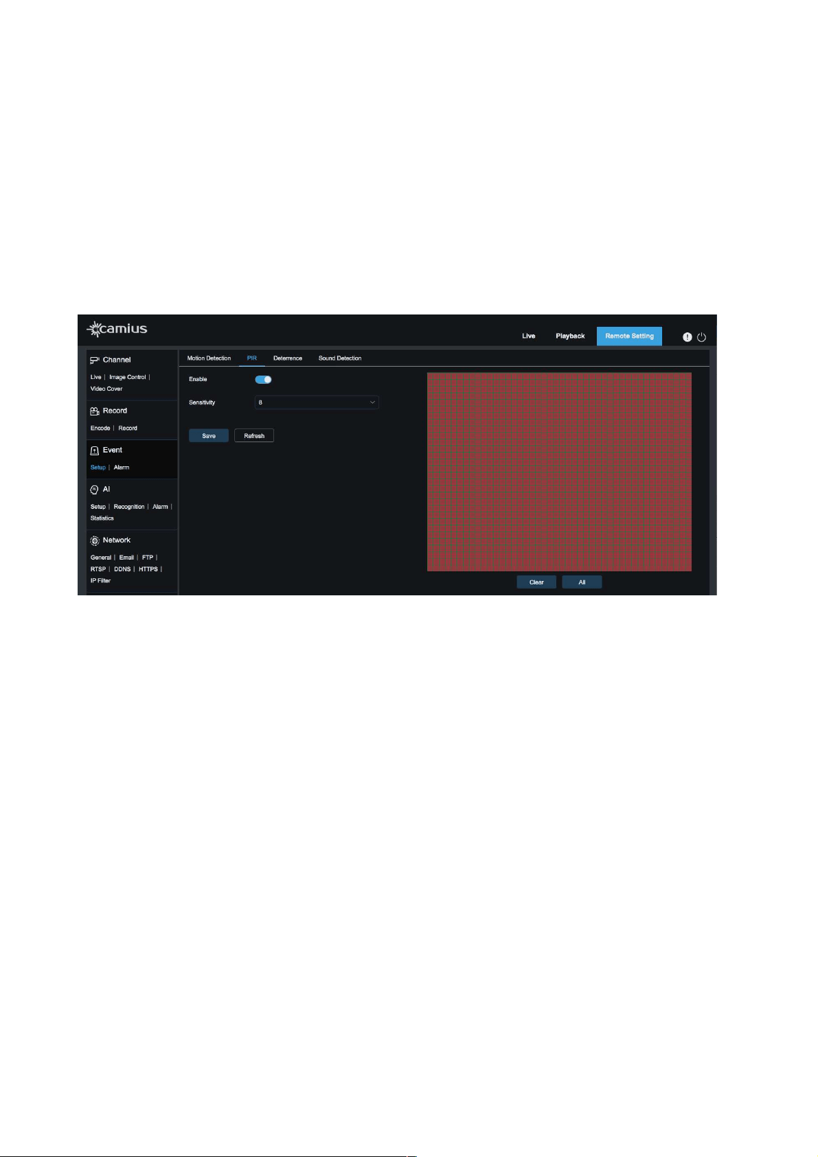
User Manual
The PIR sensor is hard-wired into the camera, which allows for deeper integration with other camera
functions like the spotlight and Siren.
Users can select hours and days of the week for the PIR sensor to work; users can also choose areas
where motion should trigger an alarm.
Users have the option to enable push notifications for PIR triggering on their smartphones.
1. Enable the ‘PIR’ detection button
2. Set the sensitivity level for PIR from 1 to 8 (larger value indicates higher sensitivity)
3. Click ‘Save’
4. If you wish to set a specific area of the view for PIR detection, hold your left mouse button and drag
out an area you target.
!
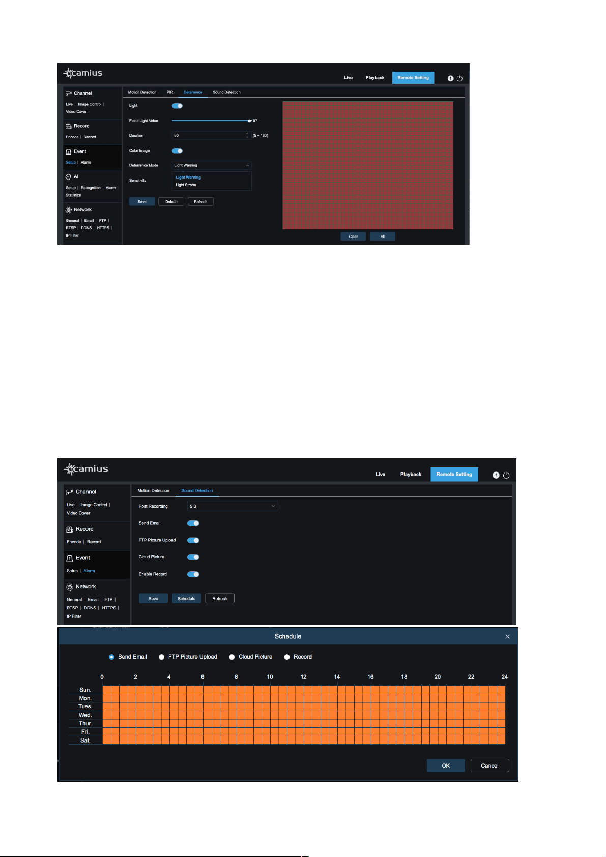
DETERRENCE
This feature applies only to certain IP cameras which have spotlights and / or a siren.
Spotlights and / or a siren provide an essential security feature: deterrence.
Motion Activated Spotlight Cameras illuminate visible and bright light into the scene, proving to deters
crime. Users can also turn the spotlight on and off using the Camius View app. Users can also Schedule
deterrence features to only be active during certain hours and days of the week. The spotlight feature
allows for clear color video in complete darkness; this helps in identifying subjects.
The built-in speaker is used to play a loud siren sound based on conditions set by the user. Volume can be
adjusted under settings so that the Siren is loud enough to do its job without bothering the neighbors. A
schedule option allows the user to define hours and days during which the Siren should be activated.
• Light: On / Off
• Flood Light Value: Select a brightness level between 1 to 100 (higher number means a brighter light)
• Duration: Enter the amount of time [in seconds reagin between 5 to 180] the light will stay on at each
event
• Color image: On / Off
• Deterrence Mode: Select ‘Light Warning’ for solid light, or ‘Light Strobe’ for a flashing light.
If you choose Strobe light mode, you will be to adjust its frequency between Low, Middle and High!
• Siren: Click on the icon to turn on the Siren [applicable only in supported devices]
Area: Set an active area for automatic deterrence. The camera image appears with a grid of red boxes over
the top. The red area is the active area for deterrence. Click or click-and-drag to add/remove boxes from
the active area. Click ‘Save’.
16
User Manual
!
3.2 Alarm
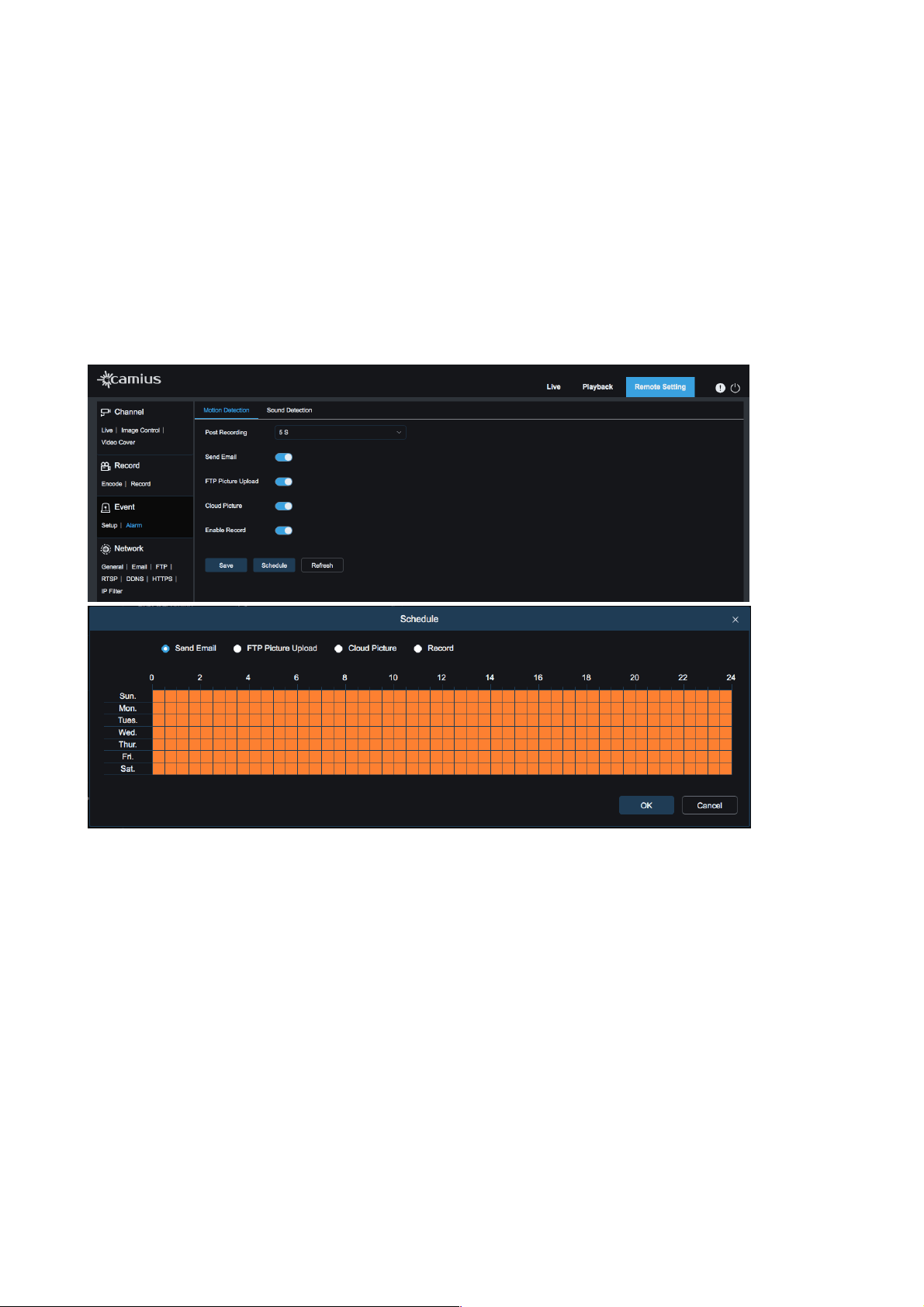
MOTION DETECTION
•
Post Recording: Select between 5, 10, 20, or 30 seconds to keep recording after the alarm has
ended. Select OFF if you do not require post-recording.
•
Send Email: Enable if you wish to send an email alert.
•
FTP Picture Upload: Enable it to upload a picture file to your FTP folder
•
Cloud Picture: Enable if you wish to upload a picture to your Cloud service (currently, it is Dropbox)
•
Enable Record: Enable it to start recording when an alarm is activated.
•
Click on 'Schedule' to set your Motion Detection alerts schedule (each read stand for 30
minutes).!You can select one of the Alarm types: Send Email, FTP Picture Upload, Cloud Picture, or
Record.
!
!
17
User Manual
SOUND DETECTION
• Post Recording: Select between 5, 10, 20, or 30 seconds to keep recording after the alarm has
ended. Select OFF if you do not require post-recording.
• Send Email: Enable if you wish to send an email alert.
• FTP Picture Upload: Enable it to upload a picture file to your FTP folder
• Cloud Picture: Enable if you wish to upload a picture to your Cloud service (currently, it is Dropbox)
• Enable Record: Enable it to start recording when an alarm is activated.
• Click on 'Schedule' to set your Sound Detection alerts schedule (each read stand for 30
minutes).!You can select one of the Alarm types: Send Email, FTP Picture Upload, Cloud Picture, or
Record.
!
!
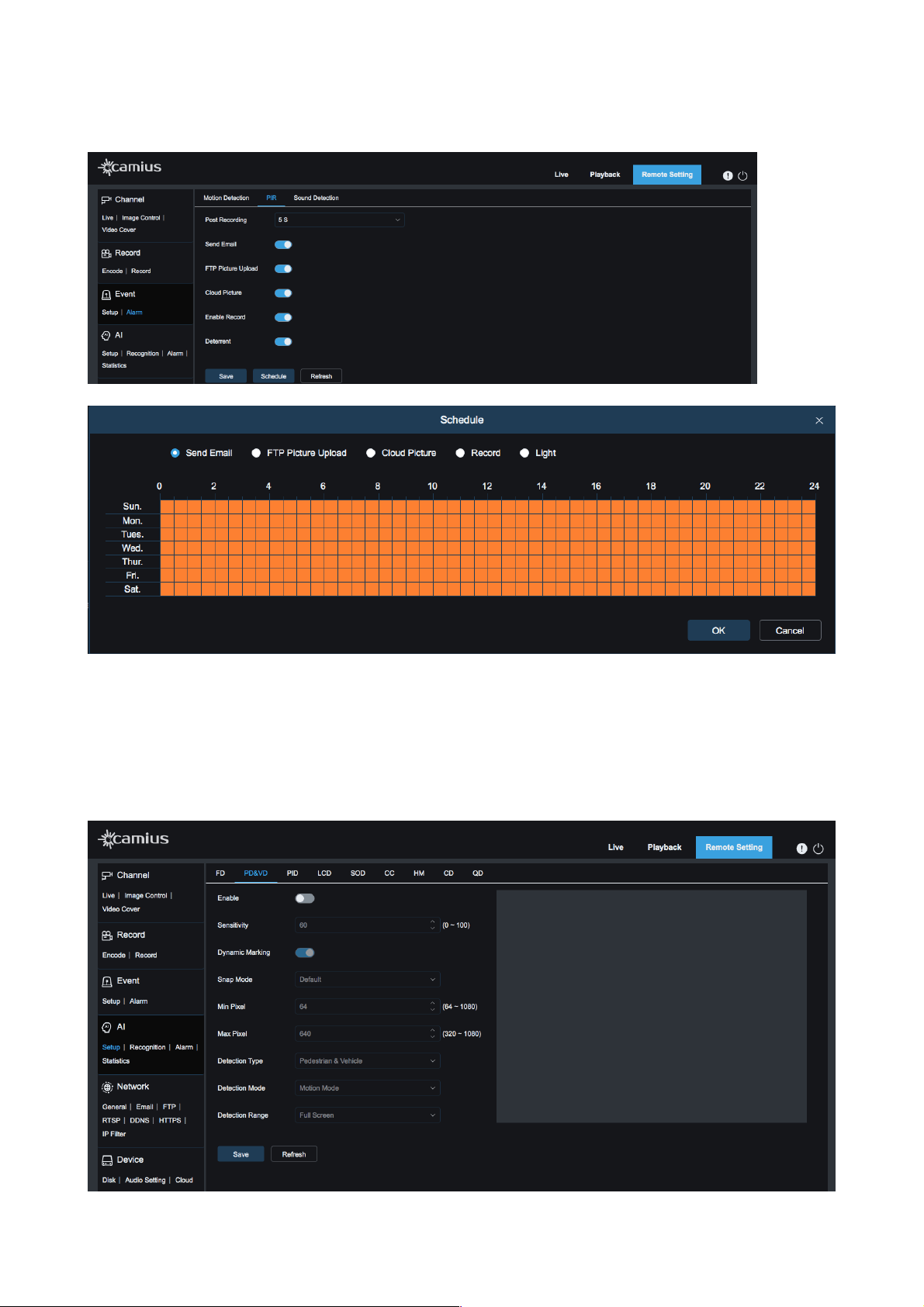
PIR
This function is available for for supported IP cameras with a built-in PIR sensor
• Post Recording: Select between 5, 10, 20, or 30 seconds to keep recording after the alarm has
ended. Select OFF if you do not require post-recording.
• Send Email: Enable if you wish to send an email alert.
• FTP Picture Upload: Enable it to upload a picture file to your FTP folder
• Cloud Picture: Enable if you wish to upload a picture to your Cloud service (currently, it is Dropbox)
• Enable Record: Enable it to start recording when an alarm is activated.
• Click on 'Schedule' to set your Motion Detection alerts schedule (each read stand for 30
minutes).! You can select one of the Alarm types: Send Email, FTP Picture Upload, Cloud Picture,
Record or [turn on ] Light
18
User Manual
4. AI
This section is available only for supported IP cameras with A.I. capabilities, which is beyond Video Motion
Detection as it allows the user to create zones for detecting movement patterns, location, etc.
19
User Manual
Intelligent Detection will trigger Push notifications in addition to video recording in a unique color and tag.
Intelligent Detection includes:
• Face Detection (FD)
• Human & Vehicle Detection (PD&VD)
• Perimeter Intrusion Detection (PID)
• Line Crossing Detection (LCD)
• Stationary Object Detection (SOD)
• Cross Counting (CC)
• Heat Map (HM)
• Crowd Density Detection (CD)
• Queue Length Detection (QD)
We are in constant development and these features are still in Beta. Please contact us at camius.com/
support for assistance and instructions.
5. Network
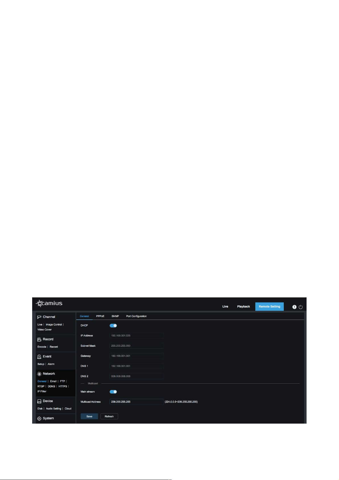
5.1 General
DHCP
DHCP: ON / OFF
DHCP stands for Dynamic Host Configuration Protocol. Enable DHCP to allow your device to automatically
obtain an I.P. address and populate the rest of the network settings. Enable it if you wish your your device
to be found on your local network automatically (Automatically Acquired), Manually Configured
Note, if you don’t enable DHCP protocol, then you need to add manually the following details:
• IP address: IP address of an IP camera
• Subnet Mask: Subnet mask of I an IP camera
• Gateway: Gateway of an IP camera
• DNS 1: Set your primary DNS server and insert the address
• DNS 2: Set your secondary DNS server and insert the address
Multicast: ON/OFF (Enable it to use multicast address for your IP camera)
!
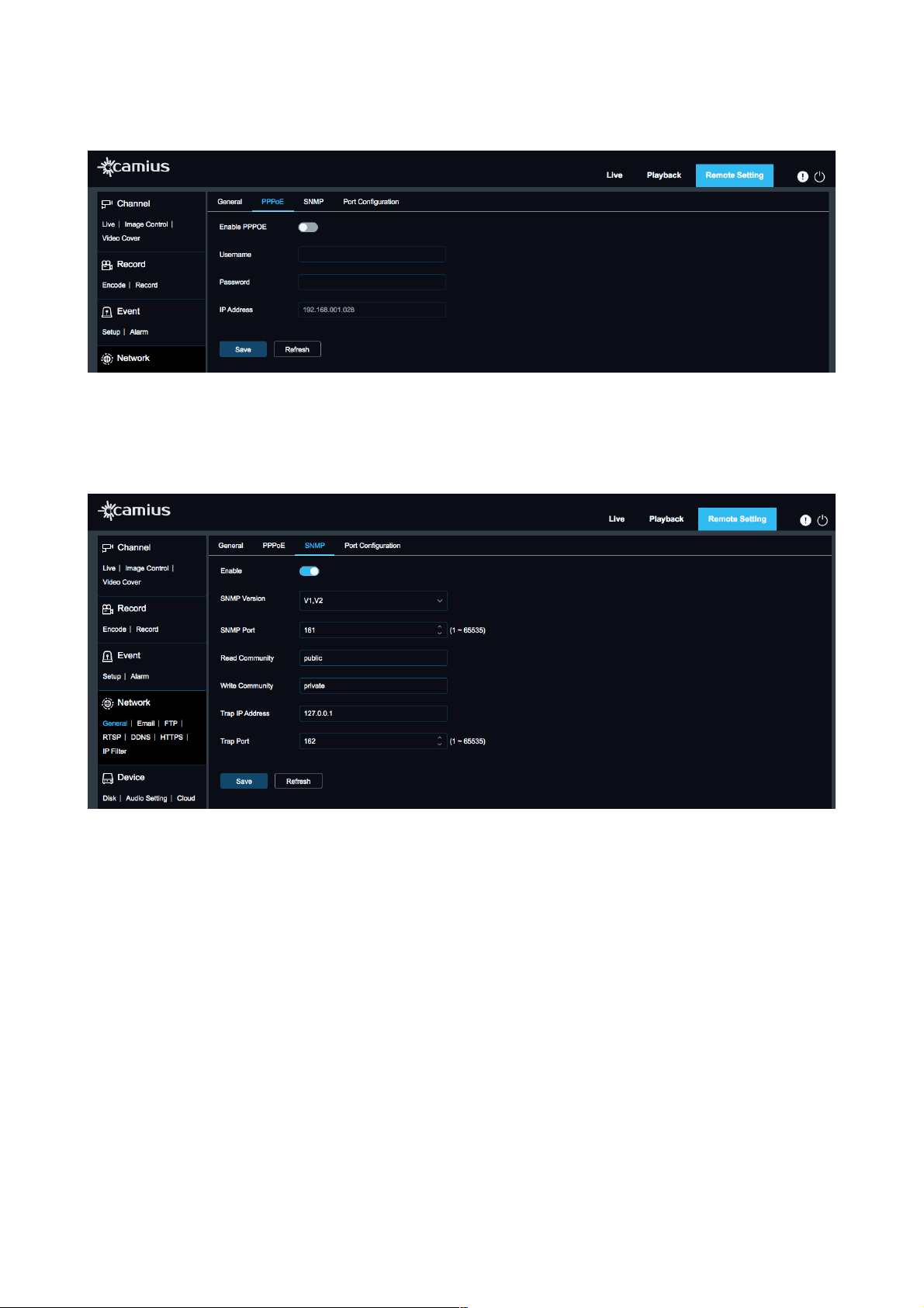
PPPOE
20
User Manual
Enable PPPoE: click on this toggle to activate it
Once you enable it, configure it manually by entering the Username, Password
!
SNMP
Click on ‘Enable’ toggle to activate SNMP
SNMP stands for the Simple Network Management Protocol to help manage cameras that are connected to
the network.
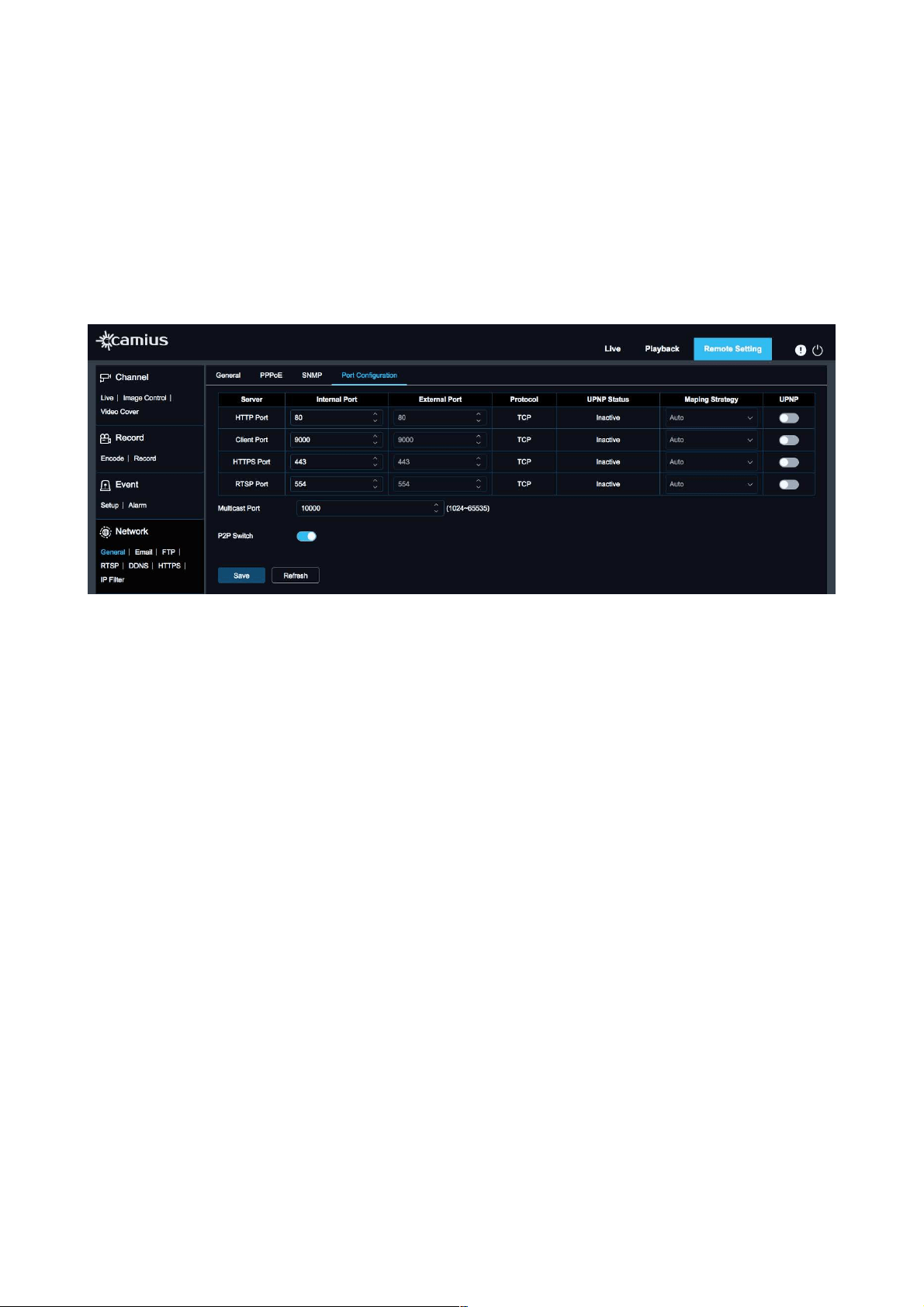
PORT CONFIGURATION:
Here you can configure manually your IP camera server, Internal & External Port, select Maping Strategy,
Enable UPNP
• HTTP Port: HTTP stand for Hypertext Transfer Protocol that!used!to display the!IP camera’s web!interface.
The default port is 80.
• Client Port: IP camera’s media port. The default media (client) port is 9988.
• HTTPS Port: HTTPS [Hypertext Transfer Protocol Secure] is the secure protocol over which data is sent
between your browser and your IP camera, showing that the communication is encrypted. Default HTTPS
port is 443.
• RTSP Port: RTSP stands for The Real-Time Streaming Protocol, and the default port is 554. This protocol
integrates the Camius IP camera with!third-party software or recorders to provide a video stream or live
streaming applications.
• Maping Strategy: One you enable UPNP, you an select between Auto & Manual Mapping Strategy
• UPNP: ON/ OFF. UPNP stands for Universal Plug and Play. By enabling it, you allow all the ports the IP
camera requires are available to it. To have the UPNP work, you need to allow it to on both IP camera and
router.
21
User Manual
Please note, to enable UPNP, the media/web/cell phone port should be set to a value between 1024 and
65535; the media port is used for connection of proprietary cell phone client; cell phone port is used for
connection of the mobile client.
• Multicast Port: select your value between 1024 to 655535
• P2P Switch: ON/OFF.
P2P stands for peer-to-peer network technology used to establish the link between
an!IP!security!camera!and your smartphone device or PC (personal computer) to view!camera!feed locally
and remotely.
!
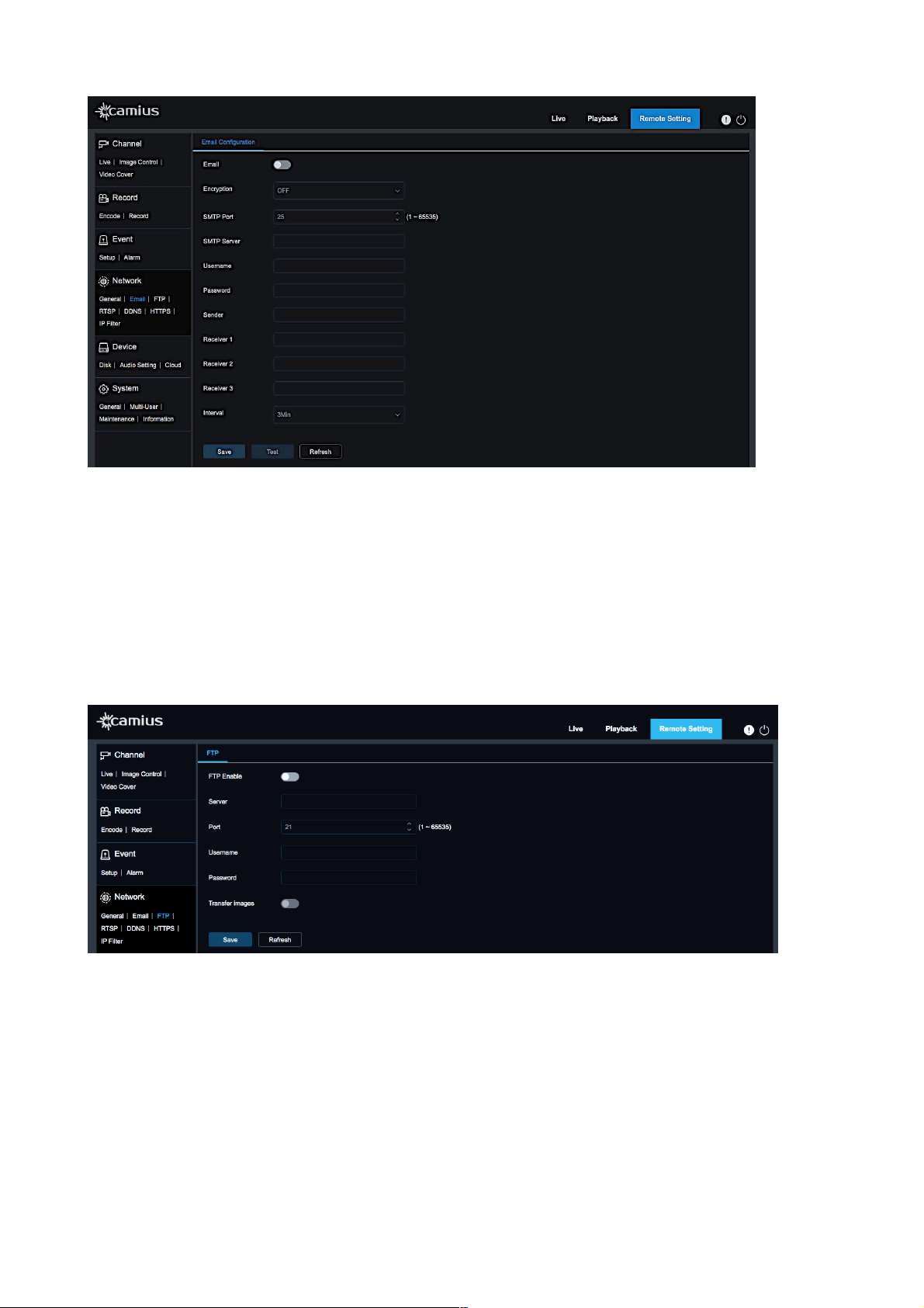
5.2 Email
Setting up a sending Email account allows your device to send you snapshots on motion detection and
other important Email alerts. Sound, PIR detection, or Intelligent video analytics. The type of event
triggering email sending depends on the camera features (Sound, PIR detection, or Intelligent video
analytics). You can configure sending emails to 3 receivers.
Email setup requires an Email account with SMTP.
The following example is for Gmail:
The first step is changing your Gmail Account Security Settings to enable Less Secure App Access, which
allows the use of your Gmail account on a device and not just on an Email client.
On your IP camera settings page, navigate to Network / Email and enter the following:
• Encryption: TLS
• SMTP Port: 587
• SMTP Server: smtp.gmail.com,
• The username: [email protected],
• Password: use the Gmail password.
• Sender: Use [email protected] in the sender field
• Receiver 1, Receiver 2, Receiver 3: add up to 3 email recipients
• Test: click the ‘Test’ button to verify your settings before saving
22
User Manual
5.3 FTP
FTP service setting IS used with alarm function to upload pictures snapped to the FTP server.
FTP: Enable or Disable it
Server: Enter the address of FTP server.
Port: FTP service port number; the default number is 21.
Username: The user name for access to FTP service
Password: The password for access to FTP service
Transfer Image: Check it to enable transferring images
!
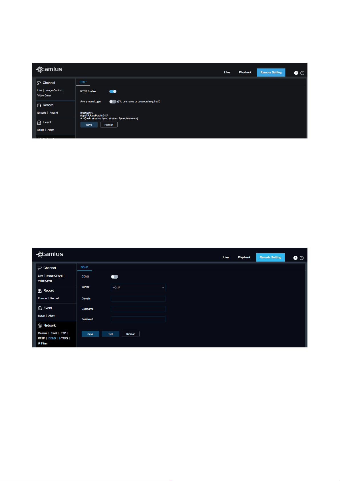
5.4 RTSP
RTSP stands for The Real-Time Streaming Protocol. This protocol integrates the Camius IP camera
with!third-party software or recorders to provide a video stream or live streaming applications.
• RTSP Enable: Enable / Disable
RTSP is enabled by default. After it is disabled, it will not be found with ONVIF.
The default RTSP port number is 554.
• Anonymous Login: Enable it if you wish to access the camera without a username or password. It is
disabled by default.
23
User Manual
• Instruction: use the following URL link template rtsp://IP:RtspPort/ch01/A where:
A: 0(mainstream), 1(Substream), 2(Mobilestream)
!
5.5 DDNS
DDNS! (Dynamic Domain Name System) allows you to access your security IP cameras over the Internet
using Dynamic IP Addresses. Your!DDNS!provider will ask you to select a username and password. In this
section, you can configure Dynamic DNS port forwarding settings used with the server for accessing the
device using the Internet.
• DDNS: ON/OFF (it is off by default)
• Server: You can select one of the following servers DDNS_3322, DYNDNS or NO-IP
• Domain: Enter the name of active server
• Username: enter the username you set with Dynamic DNS
• Password: enter the password you set with Dynamic DNS
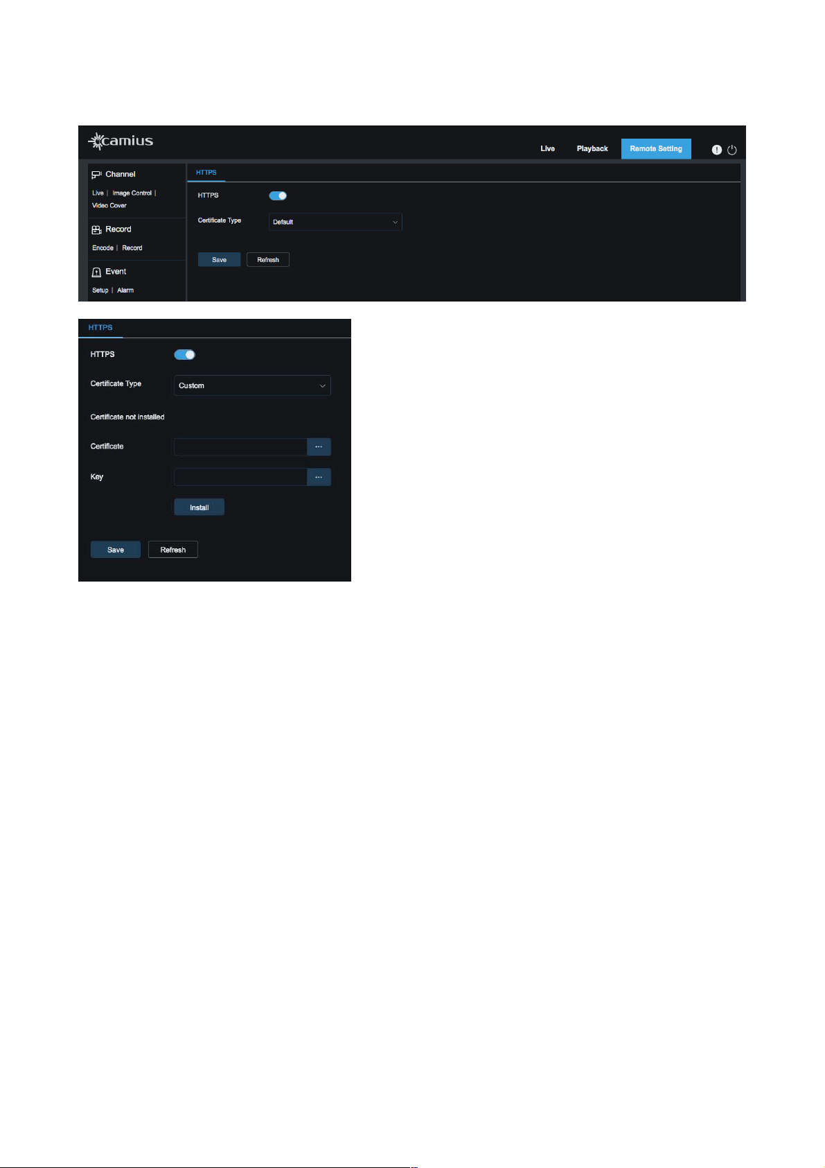
5.6 HTTPS
HTTPS [Hypertext Transfer Protocol Secure] is the secure protocol over which data is sent between your
browser and your IP camera, showing that the communication is encrypted. Default HTTPS port is 443.
• HTTPS: ON / OFF
• Certificate Type: Default / Customs
If you select the customs certificate you need to install it by uploading the certificate and key.
Make sure to Save your new settings
24
User Manual
Certificate Type: Default / Custom
If you select the Custom certificate, you need to install it by uploading the certificate and key.
Make sure to!save!your new settings.
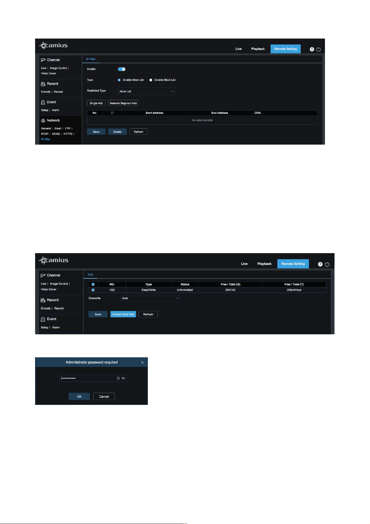
5.7 IP Filter
In this section, you can control which! IP! addresses can connect to your IP! camera. If you enable it, you
have the option to limit!IP!addresses in 2 ways: You can deny or allow access to specific!IP!addresses or a
range of IP addresses.
• Enable: select it if you wish to enable IP filter feature
• Type: select the type of the list you wish to work on
-
Enable Allow List
- Enable Block List
• Single Add: Add a single IP address
• Network Segment Add: Add a range of IP addresses
•
Delete: Delete any IP address added previously
• Make sure to click ‘Save’ once you modify settings
25
User Manual
!
6. Device
6.1 Disk
This feature is available to those IP cameras which have a built-in SD slot for a micro SD. The supported
capacity is 256GB. We recommend using a high-class micro SD.
Once you insert an SD card into the IP camera, the system will auto-detect the total capacity and balance
capacity of SD card, type of the card, the total, and remaining free capacity of time to record.
If the SD card status is displayed as ‘Unformatted’, please click ‘Format Hard Disk’
!
It will prompt you to enter your administrator password. Once the disk is formatted, you will get a message
confirming that the disk formatting was successful.
!
Overwrite: select Auto or OFF. If you choose 'Auto', when the SD card's capacity is 0 (zero), new
recordings will overlap previous recordings (this function is the default). Click Save if you modify Overwrite
settings.
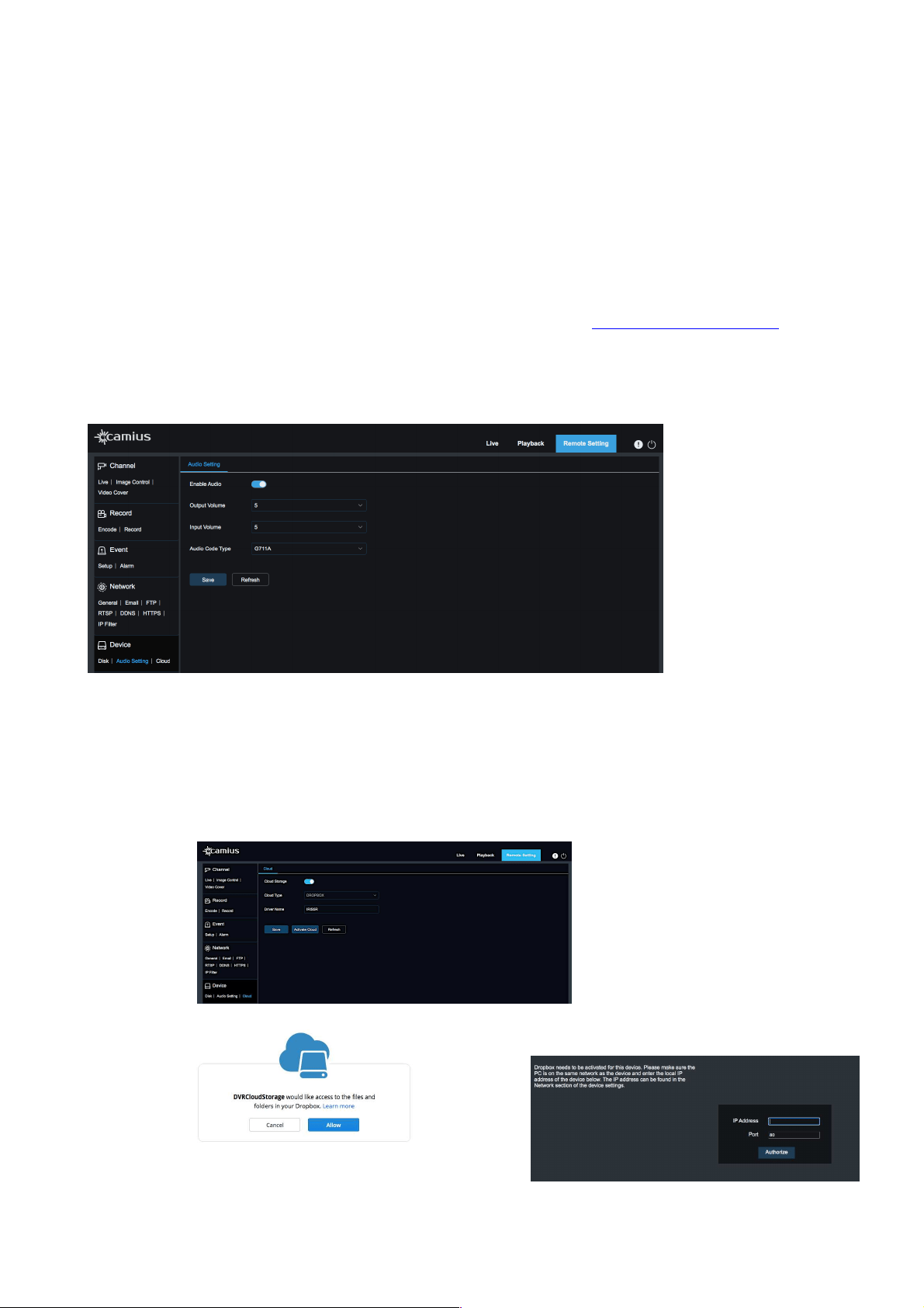
6.2 Audio Setting
On this page, you can control your IP camera's audio settings. You can enable and disable the IP camera's
Audio, adjust the volume, select the!audio code type.
26
User Manual
If an IP camera has only a built-in microphone to record and monitor clear audio, you will control input
volume. However, if the IP camera comes with a built-in speaker to talk (or for the siren sound enabling)
then you can adjust the audio output volume on this page.
Audio can be disabled in the camera settings page, and when enabled, it will be combined and
synchronized with video footage.
• Enable Audio: ON / OFF
Once you enable Audio, click Save and make sure!to access audio settings, set audio input, output volume
(ranging 0~10), and then click!Save again.!
Note: For the application of an audio function, the audio option in the 'Record - Encode - Stream' setting
needs to be enabled
• Input Volume: to adjust a camera's microphone's volume with an adjustable level 0~10
• Output Volume: to adjust a camera's speaker's volume with an adjustable level 0~10
• Audio Code Type: Select between G711A or G711U
!
6.3 Cloud
To activate Cloud Storage first click the Cloud Storage toggle to active mode then click ‘Save' and then
click 'Activate Cloud' (Picture 1) which will redirect you to ‘Dropbox' (Picture 2 & Picture 3) where you'll be
able to sign up or login and confirm access, them you'll be redirected back to the Device Interface to fine-
tune your Cloud Storage preferences.
!
27
Picture 1
Picture 2
Picture 3
User Manual
7. System
7.1 General
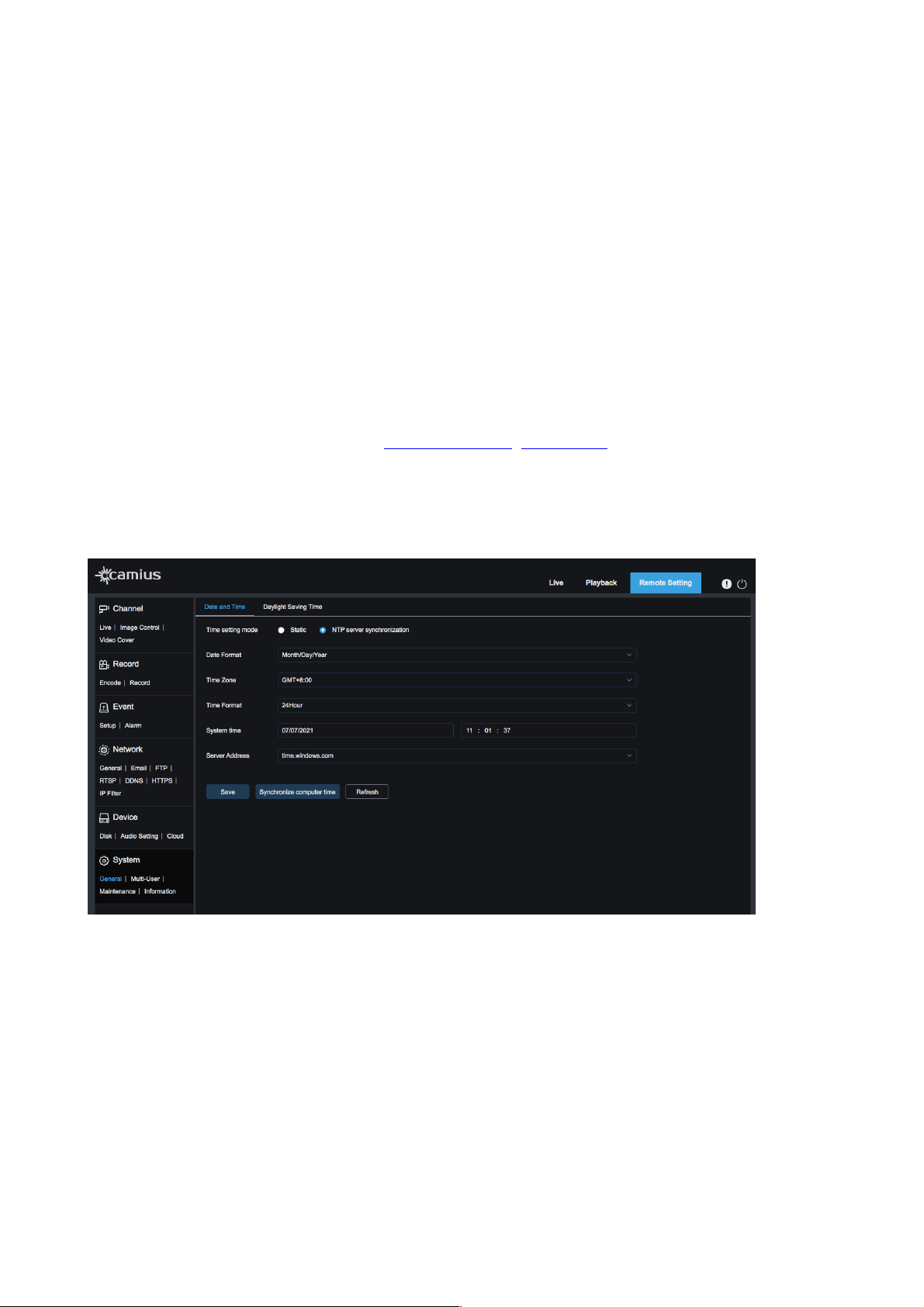
DATE AND TIME
• Time setting mode: There are 2 option to choose from, ‘Static’ or ‘NTP server synchronization’ (the
default is NTP server synchronization). Check Enable NTP option, input the address of time server and
choose a time zone and then save the setting. The system will correct time in accordance with the time
server.
• Date Format: Select format to display the date (Month/Day/Year, Year-Month-Day, or Day/Month/Year)
• Time Zone: select your time zone
• Time Format: 24Hour or 12Hour
• System Time: Set your system time
• Server Address: Select server address (time.windows.com, time.nist.gov, or Define User)
• Save: to save modified setting
• Synchronize Computer Time: click on this tab so your device will use PC as a time server to correct
time.
Please make sure to refresh the page after saving settings.
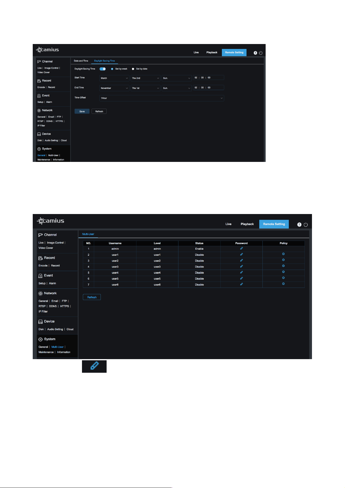
DAYLIGHT SAVING TIME
• Daylight Saving Time: Check Daylight Savings Time (DST) option to enable DST correction.
• Choose to ‘Set by week’ or ‘Set by date’
• Start Time: set the date and end time of Daylight Saving Time
• End Time: set the date and end time of Daylight Saving Time
• Time Offset: select 1Hour or 2Hours
28
User Manual
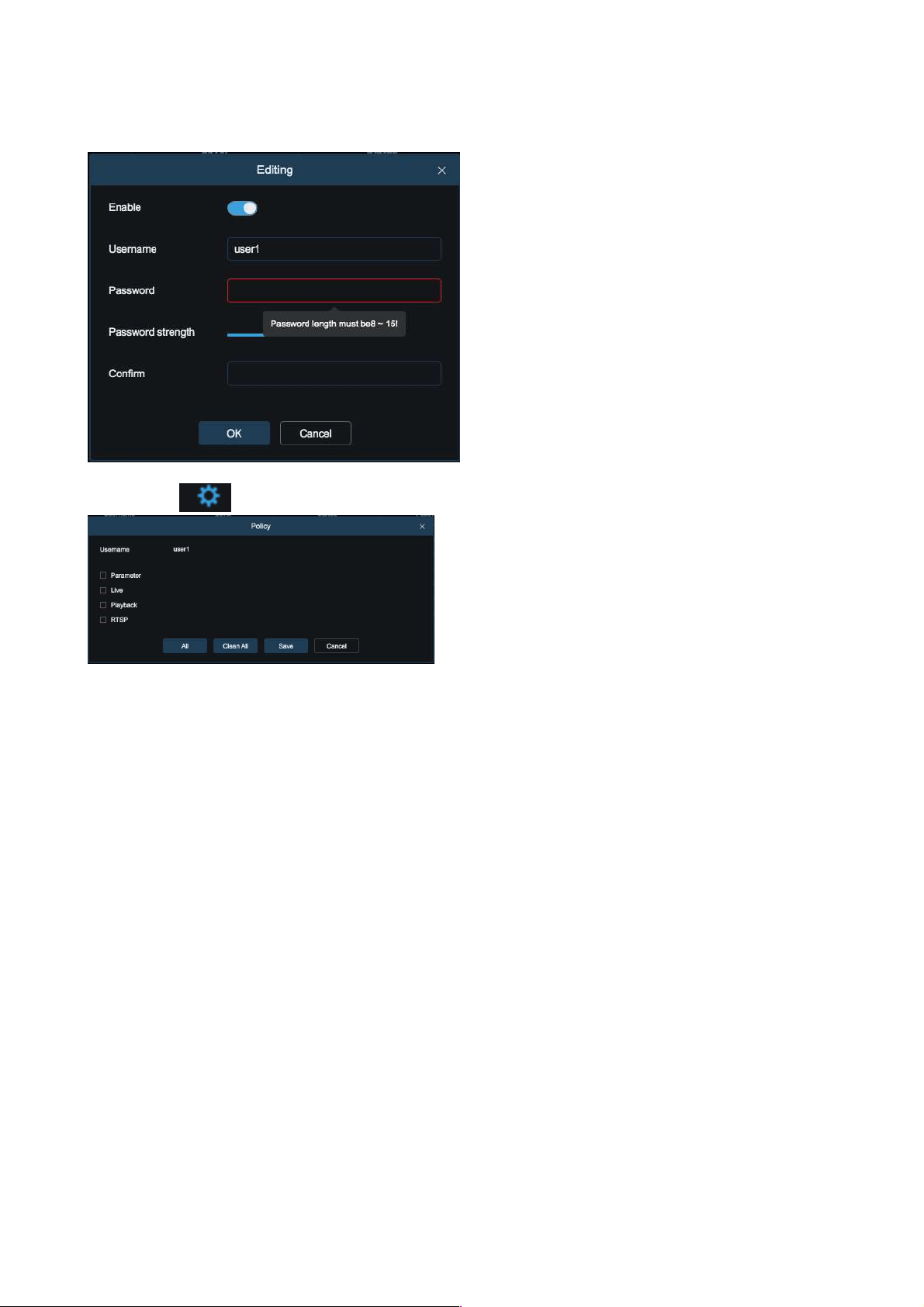
7.2 Multi-user
On this page you, as the administrator, can set user access authority and login password.
Up to 6 users can be added to the system.
Click on this icon which will prompt the below pop-up window allowing the administrator to
enable a user, edit the user's username and password (password length must be between 8 to 15
characters). Next, you will be able to see the strength of the password. Finally, the administrator will be able
to see if the
password is strong enough. Once the password is selected, enter it again in the ‘Confirm” line and click
‘Ok’.
29
User Manual
Click on the icon to edit to what settings the user can access: Parameter, Live, Playback, RTSP.
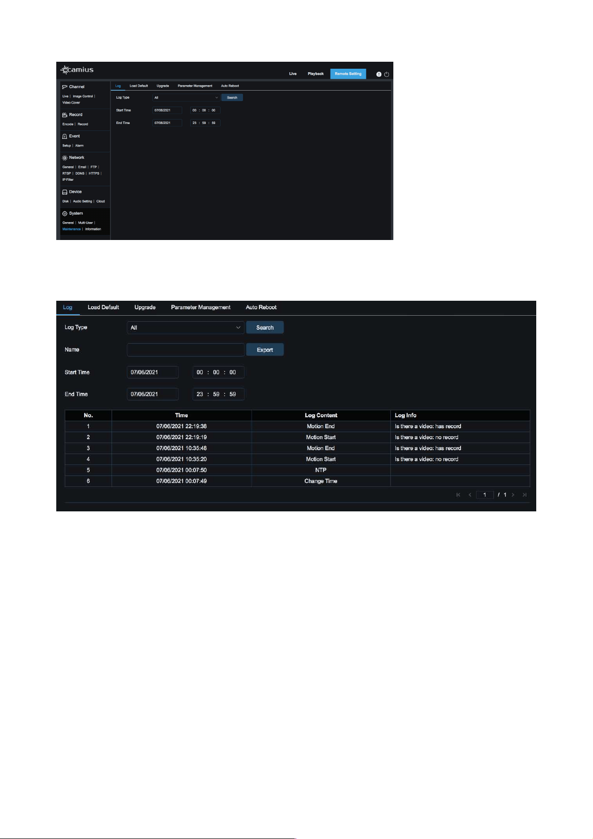
7.3 Maintenance
7.3.1 Log
Log Type - Eight types of logs are available for search:
1. System
2. Configuration
3. Alarm
4. Account
5. Record
6. Storage
7. Network
8. All
30
User Manual
!
Start Time - select the starting date and time for retrieval
End Time - select the ending date and time for retrieval
Click on "Search" to retrieve and display related logs in the table below.
Name: Enter a filename for log file & click ‘Export’ (saves to directory specified in Path)
!
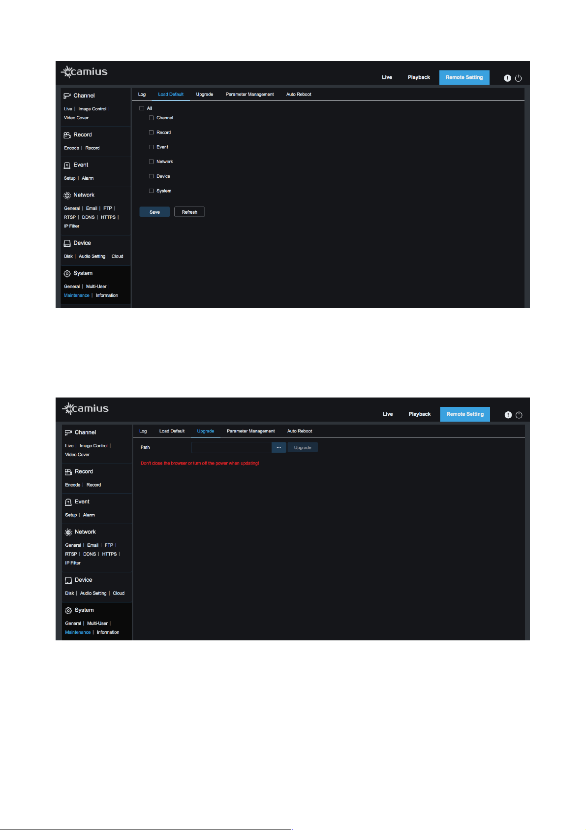
7.3.2 Load Default
Click on 'Load Default' in the System-Maintenance menu to reset your IP camera to default settings. Check
the options you require and click on ‘Save'.
31
User Manual
7.3.3 Upgrade
Firmware Update in Advanced menu allows upgrading the IP camera's firmware. An update will be
unavailable if the update files do not match the selected device.
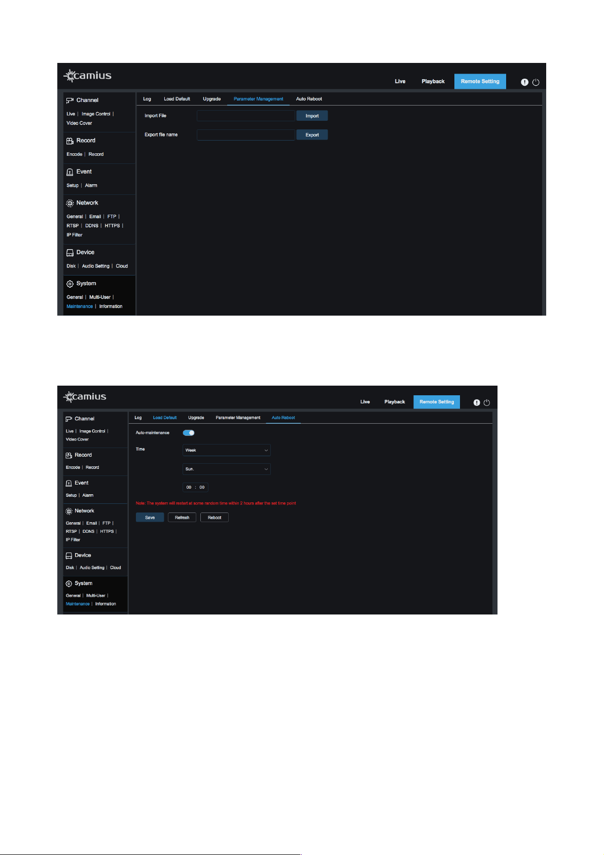
7.3.4 Parameter Management
• Import File: Enter the file location to import a configuration file
• Export File Name: Enter the file location to export a configuration file
32
User Manual
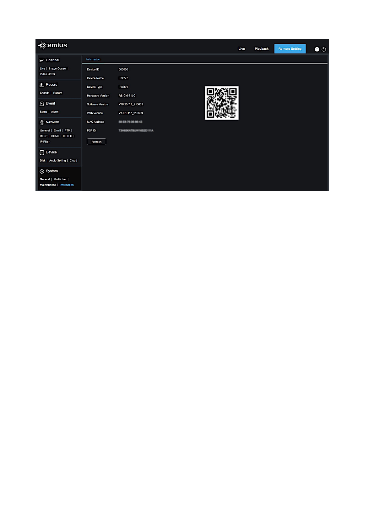
7.3.5 Auto Reboot
Click the ‘Auto-maintenance’ toggle to active mode to to schedule a periodical IP camera restart Weekly/
Daily or Monthly, select the day of the week and time. Or click on ‘Reboot’ to restart it manually.
!
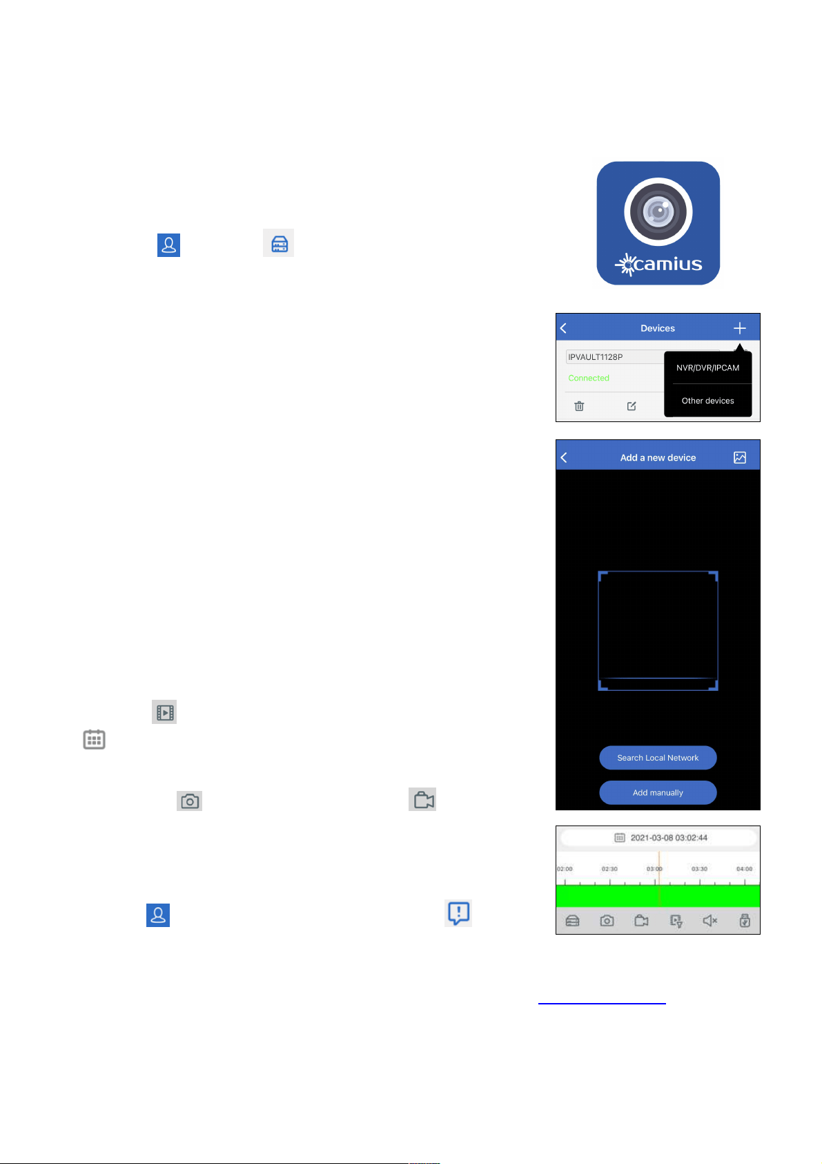
7.4 Information
The device system information is displayed here, including device ID, name, type, hardware, and software
version, web version, MAC address, and P2P ID. You can visit a mobile app through the P2P QR code
instantly by scanning it.
33
User Manual
!
34
User Manual
————————————————————————————————————————————————
CAMIUS VIEW
ADDING YOUR IP CAMERA ON THE CAMIUS VIEW APP FOR SMARTPHONES AND
TABLETS
•
Tap on the icon then on Devices to open the device list page,
tap on the + to add a new device.
• Choose NVR/DVR/IPCAM and then Search Online Network to add
devices on your network.
• On the device page, enter the password you set earlier and save. The
App will confirm once connected.
• There are two other ways to add your device:
-
While you have the QR code scanner active, point your smartphone
camera to the QR code, which is available under the information tab on
your device, you can also scan the code on the label attached to your
device.
-
Adding your Camius device manually.
LIVE VIEW
On the main App View page, tap on a device to view its channels, double-
tap on a channel to zoom in, and again to go back to multi-view.
You can also zoom in a single channel with the spread gesture and zoom
out by pinching.
Switching to landscape mode on your smartphone or tablet gives you a
full-screen view.
PLAYBACK
Tap on the icon to launch playback, then tap on the calendar icon
to pick a day with recordings.
Scroll the bottom colored bar horizontally to pick the time of day for
playback, The icon saves a snapshot, and the icon records on
demand into your smartphone or tablet’s storage.
ENABLING PUSH NOTIFICATIONS
Tap on the icon and then on the Push Notifications icon , select the
device and enable the desired per channel motion detection alerts, disk
error detection alerts, and more.
35
Here at Camius, we are committed to improving our products, therefore user guides, manuals, instructions will be improved along with these developments.
Your feedback is important to us. Please submit your comments and suggestions visiting the following link https://camius.com/contact/
Legal Disclaimer: The information in this document is subject to change without notice and should not be construed as a commitment by Camius.com. Camius assumes no
responsibility for any errors that may appear in this document. In no event shall Camius be liable for incidental or consequential damages arising from the use of this
document or the software and hardware described in this document. This document and parts thereof must not be reproduced or copied without Camius written permission,
and contents thereof must not be imparted to a third party nor be used for any unauthorized purpose.