Loading ...
Loading ...
Loading ...
7
3. Remove the knockouts (if necessary) or use the provided cable clamp.
4. Pull out the four wires marked L1, L2, N, and G.
5. Connect L1 (black) wire from the unit to the L1 (black) from the power supply.
6. Connect L2 (red) and N (white) from the unit to the Neutral (white) from the power supply.
7. Connect the ground wire (green) from the unit to the ground from the power supply.
8. When the unit has been congured for the appropriate power supply voltage, ensure that all connections are tight.
9. Insert all the wiring back into the unit and secure with a cable clamp.
!
IMPORTANT: The unit is factory congured for 208/240V operation.
!
NOTE: Use 2 conductor wires with ground (3 wires total) from the power supply (breaker panel) to the junction box on the
unit.
!
NOTE: All wiring must be completed prior to installing the unit.
!
NOTE: Ensure that the voltage selector switch is in the proper position for the required supply voltage prior to connecting
the unit to the power supply.
!
NOTE: PurireTM will operate without heat in this application.
1. Locate the voltage selector switch inside the exhaust panel on the top right hand corner of the unit. Flip the switch from
240V to 120V conguration. (230 and 115 is printed on switch)
2. Loosen the screw securing the junction box cover and remove the cover.
3. Remove the knockouts (if necessary) or use the provided cable clamp.
4. Pull out the four wires marked L1, L2, N, and G.
5. Connect L1 (black) wire from the unit to the L1 (black) from the power supply.
6. Connect L2 (red) and N (white) from the unit to the Neutral (white) from the power supply.
7. Connect the ground wire (green) from the unit to the ground from the power supply.
8. Locate and separate, by installing a wire nut on the 1 (red) and 2 (red).
9. When the unit has been congured for the appropriate power supply voltage, ensure that all connections are tight.
10. Insert all the wiring back into the unit and secure with a cable clamp.
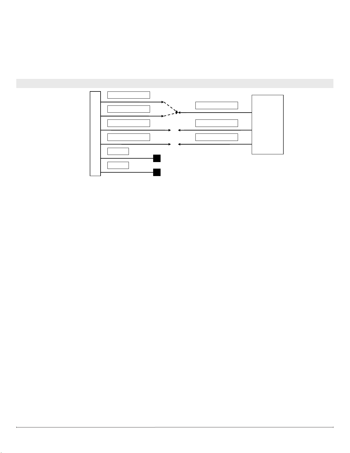
FIREPLACE JUNCTION BOX
120 V
POWER
SUPPLY
(BREAKER
PANEL)
WHITE WIRE - N
RED WIRE – L2
BLACK WIRE – L1
GREEN WIRE - G
WHITE WIRE - N
BLACK WIRE – L1
GROUND WIRE - G
RED - 1
RED - 2
WIRE NUTS
120V INSTALLATION - NO HEAT INSTALLATION
Loading ...
Loading ...
Loading ...