Loading ...
Loading ...
Loading ...
13
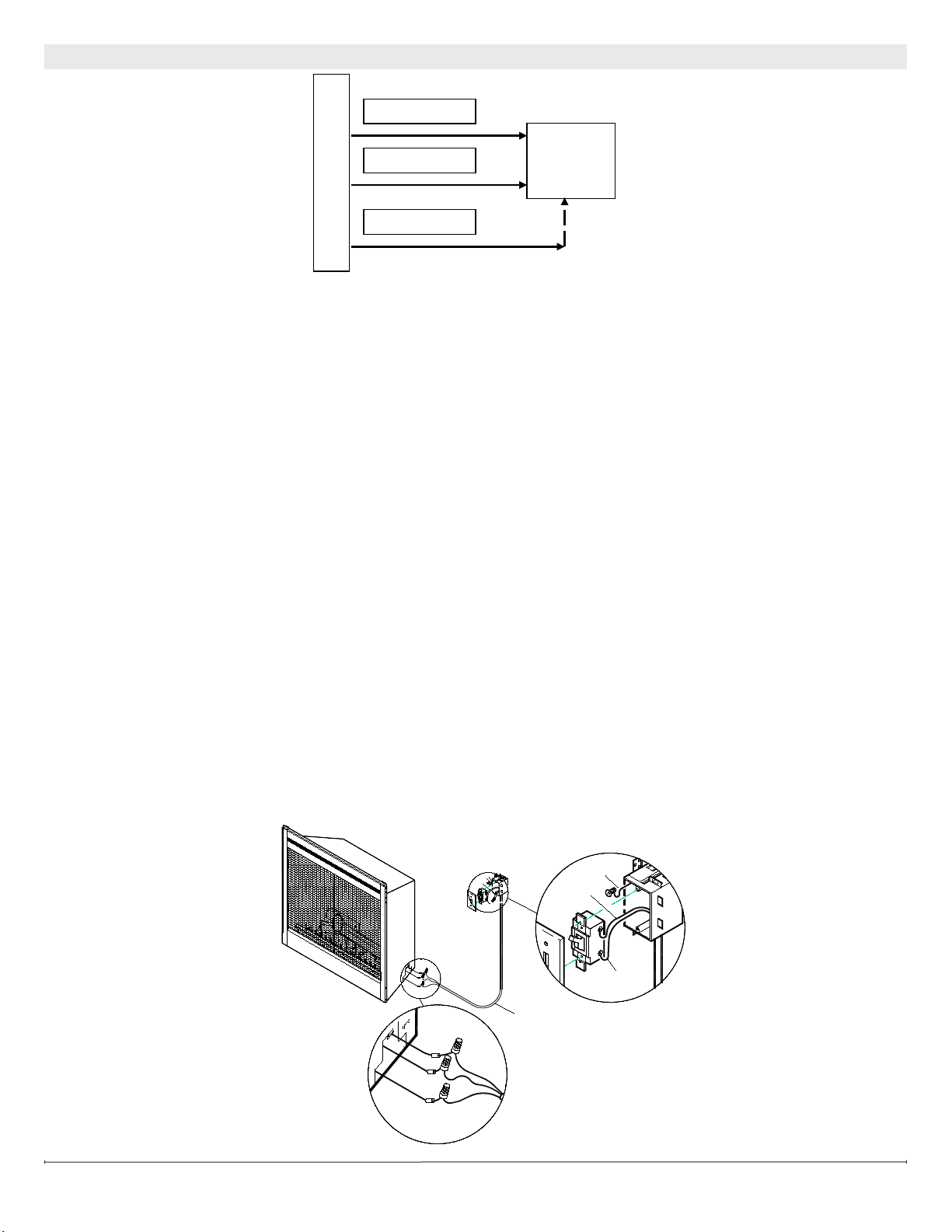
120V/240V WALL MOUNTED FLAME OVERRIDE SWITCH
DO NOT USE WITH NO HEAT INSTALLATIONS
!
NOTE: The replace can be wired to have a wall switch operate the ame independent of the heater.
!
NOTE: Before installing the unit complete the following:
1. Install main power connection with appropriate wiring - directly to the main power or through a wall switch.
2. Install a 2 conductor wire with ground (3 wires total) from the ame override switch wall box to the junction box
on the unit.
!
NOTE: Use a wall switch (On/Off) that is rated for a minimum of 15 amps.
1. Loosen the screw securing the junction box cover and remove the cover.
2. Remove the knockouts (if necessary) or use the provided cable clamp.
3. Pull out the three wires marked 3, 4, and G (blue, blue, and green).
4. Remove the wire connector and separate the wires marked 3 and 4.
5. Connect 3 wire (blue) from the unit to the L1 wire (black) from the ame override wall switch by using a wire connector
(not supplied).
6. Connect the other end of the L1 wire (black) from the ame override wall switch to the L1 terminal of the ame override
wall switch.
7. Connect 4 wire (blue) from the unit to the Neutral wire (white) from the ame override wall switch using a wire connector
(not supplied).
8. Connect the other end of the Neutral wire (white) from the ame override wall switch to the L2 terminal of the ame over-
ride wall switch.
9. Connect the Ground wire (green) from the unit to the Ground wire (green) from the ame override wall switch using a wire
connector (not supplied).
10. Secure the remaining Ground wire (green) with a ground screw in the ame override switch wall box.
11. Ensure that all connections are tight.
12. Insert all the wiring of the heater wall switch into the heater switch wall box.
13. Insert all the wiring back into the unit and secure with a cable clamp.
FIREPLACE JUNCTION BOX
BLUE – 4
WALL
SWITCH
BLUE – 3
GROUND - G
UNIT
FROM FLAME OVERRIDE SWITCH
2
1
G
L1 FROM UNIT
G FROM
POWER SUPPLY
G FROM UNIT
L1 FROM
POWER SUPPLY
NEUTRAL FROM
UNIT AND SUPPLY
UNIT
WIRE 3 FROM
G FROM UNIT
WIRE 4 FROM
G
4
3
2 CONDUCTOR WIRE
!
NOTE: This only illustrates
ame switch connection,
see previous sections for
main power connection
instructions.
Loading ...