Loading ...
Loading ...
3
The BF series replaces have been tested in accordance with the UL 2021 and CSA C22.2 No. 46 standards for xed and
location-dedicated electric room heaters.
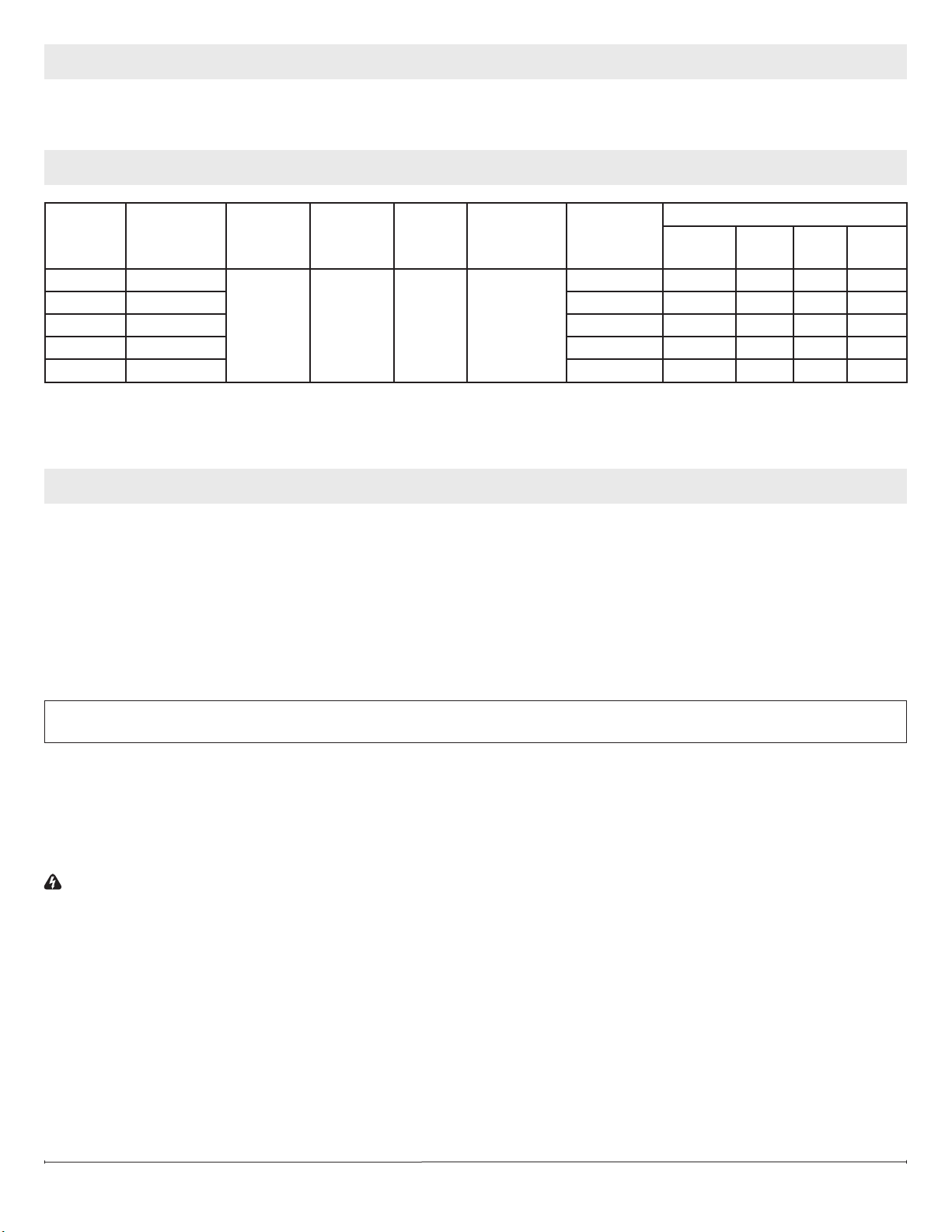
Model
Number
Description Voltage
Rated
Power
(Watts)
Remote
Control
Wall
Thermostat
Refractory
Brick Look
Current Draw (Amps)
No Heat
120V
120V 208V 240V
BF45DXP 45” Deluxe
120/120/
208/240
245/1440/
2100/2700
Optional Optional
Included 2.0 12.0 10.10 11.25
BF39DXP 39” Deluxe Included 2.0 12.0 10.10 11.25
BF39STP 39” Standard N/A 2.0 12.0 10.10 11.25
BF33DXP 33” Deluxe Included 2.0 12.0 10.10 11.25
BF33STP 33” Standard N/A 2.0 12.0 10.10 11.25
!
NOTE: Power ratings shown include the light bulbs and motors (275 watts)
The installation of the fireplace unit must comply with the applicable Local and/or National Electrical Codes and utility require-
ments. This installation should be entrusted to duly qualified personnel where required by law.
MODEL SPECIFICATIONS
LISTING AND CODE APPROVALS
!
NOTE: Please read all instructions before installing.
1. Rough in framing opening following the recommended dimensions located in Section A: Framing Dimensions.
2. Allow 8” (20.3 cm) of service cable for connecting power supply wire to junction box on replace when installing before
nishing wall. Allow up to 4’ (121.9 cm) of service cable for connecting power supply wire to junction box on replace
when installing after nishing wall. Remove the outer jacket and strip the individual conductors ½” (1.3 cm) from the end.
3. Loosen the screw securing the junction box cover and remove the cover.
4. Remove knockouts, if necessary, or use the provided cable clamp.
5. Place unit in position in the framed opening, level with shims if necessary and attach unit to frame using mounting anges
provided (Figure 2).
6. Unit is factory wired for 208/240V power supply. If 120V operation is required, slide the switch and recongure the wiring
(Section C). Wires L1, L2, N & G are attached to the rear of the junction box cable clamp for easy access.
!
NOTE: If wiring unit to operate with NO heat a dedicated circuit may not be required.
7. Wire a dedicated, properly fused circuit with a 15amp rating for the appropriate voltage (120V, 208/240V). See Section C
for factory setting wiring.
8. Make wall switch and or wall mounted thermostat connections as outlined in Section D.
9. Place all connectors inside the unit and secure the junction box cover to unit. Ensure that the cable clamp grips only the
jacket of service cable, thermostat and if applicable wall switch lines.
WARNING: Ensure method of installation does NOT obscure the air intake slots on bottom front of unit in any manner.
(See diagram in Section A)
STEP-BY-STEP INSTALLATION
Loading ...
Loading ...
Loading ...