Loading ...
Loading ...
Loading ...
SECTION4: TRACTORSET-UP
AttachingtheSteeringWheel
ToolsRequired
(1) 1/2" socket wrench
1. The hardware for attaching the steering wheel has
been packed within the steering wheel, beneath
steering wheel cap. Carefully pry off the steering
wheel cap and remove the hardware.
2. With the wheels of the tractor pointing straight
forward, place the steering wheel over the steering
shaft.
3. Place the washer (with the cupped side down) over
the steering shaft and tightly secure with the hex
bolt. See Figure 1.
Cap
........ SteeringShaft
\
,
Figure 1
Place the steering wheel cap over the center of the
steering wheel and push downward until it "clicks"
into place.
AttachingtheBatteryCables
ToolsRequired
(1) 7/16" wrench
WARNING: California Proposition 65
Warning: Battery posts, terminals, and
related accessories contain lead and lead
compounds, chemicals known to the State of
California to cause cancer and reproductive
harm. Wash hands after handling.
NOTE: Your tractor's battery cables may have
already be attached at the factory.
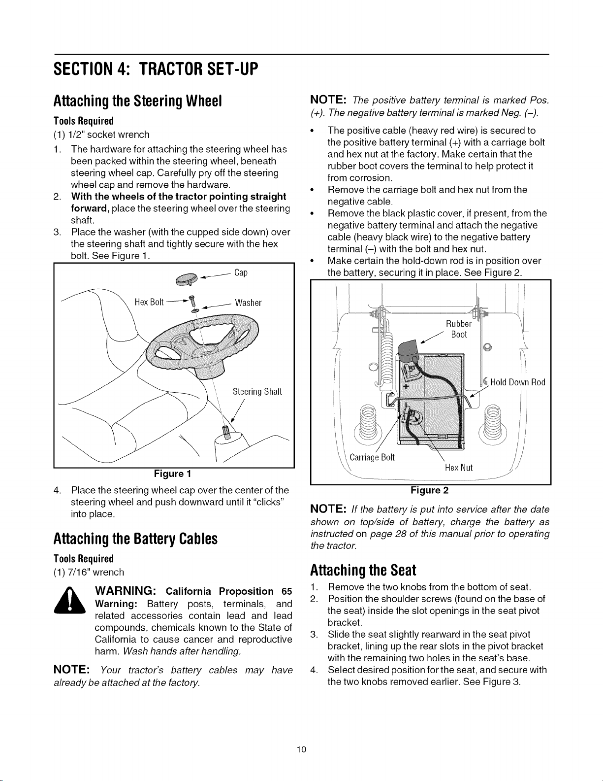
NOTE: The positive battery terminal is marked Pos.
(+). The negative battery terminal is marked Neg. (-).
• The positive cable (heavy red wire) is secured to
the positive battery terminal (+) with a carriage bolt
and hex nut at the factory. Make certain that the
rubber boot covers the terminal to help protect it
from corrosion.
• Remove the carriage bolt and hex nut from the
negative cable.
• Remove the black plastic cover, if present, from the
negative battery terminal and attach the negative
cable (heavy black wire) to the negative battery
terminal (-) with the bolt and hex nut.
• Make certain the hold-down rod is in position over
the battery, securing it in place. See Figure 2.
©
H01dDownRod
CarriageBolt
HexNut
Figure 2
NOTE: If the battery is put into service after the date
shown on top/side of battery, charge the battery as
instructed on page 28 of this manual prior to operating
the tractor.
Attachingthe Seat
1. Remove the two knobs from the bottom of seat.
2. Position the shoulder screws (found on the base of
the seat) inside the slot openings in the seat pivot
bracket.
3. Slide the seat slightly rearward in the seat pivot
bracket, lining up the rear slots in the pivot bracket
with the remaining two holes in the seat's base.
4. Select desired position for the seat, and secure with
the two knobs removed earlier. See Figure 3.
10
Loading ...
Loading ...
Loading ...