U)
0
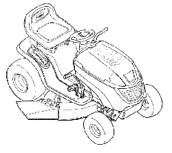
LX466 Lawn Tractor
Model No. 13RT61RH044
Model No. 13RT61RH244
Model No. 13AT61RH048
Register your product at www.Toro.com Original Instructions (EN)
769-03480 (11/27/07)
California Proposition 65 Warning:
WARNING: Engine exhaust, some of its constituents, and certain vehicle components contain or
emit chemicals known to the State of California to cause cancer and birth defects or other
reproductive harm.
TABLEOFCONTENTS
Content Page
Important Safe Operation Practices 3
Slope Gauge 9
Tractor Set-up 10
Know Your Lawn Tractor 13
Operating Your Lawn Tractor 17
Making Adjustments 21
Maintaining Your Lawn Tractor 23
Content Page
Service 27
Off-season Storage 30
Maintenance Chart 31
Troubleshooting 32
Specifications 33
Warranty Information 35
FINDINGMODELNUMBER
This Operator's Manual is an important part of your new lawn tractor. It will help you assemble, prepare and maintain the
unit for best performance. Please read and understand what it says.
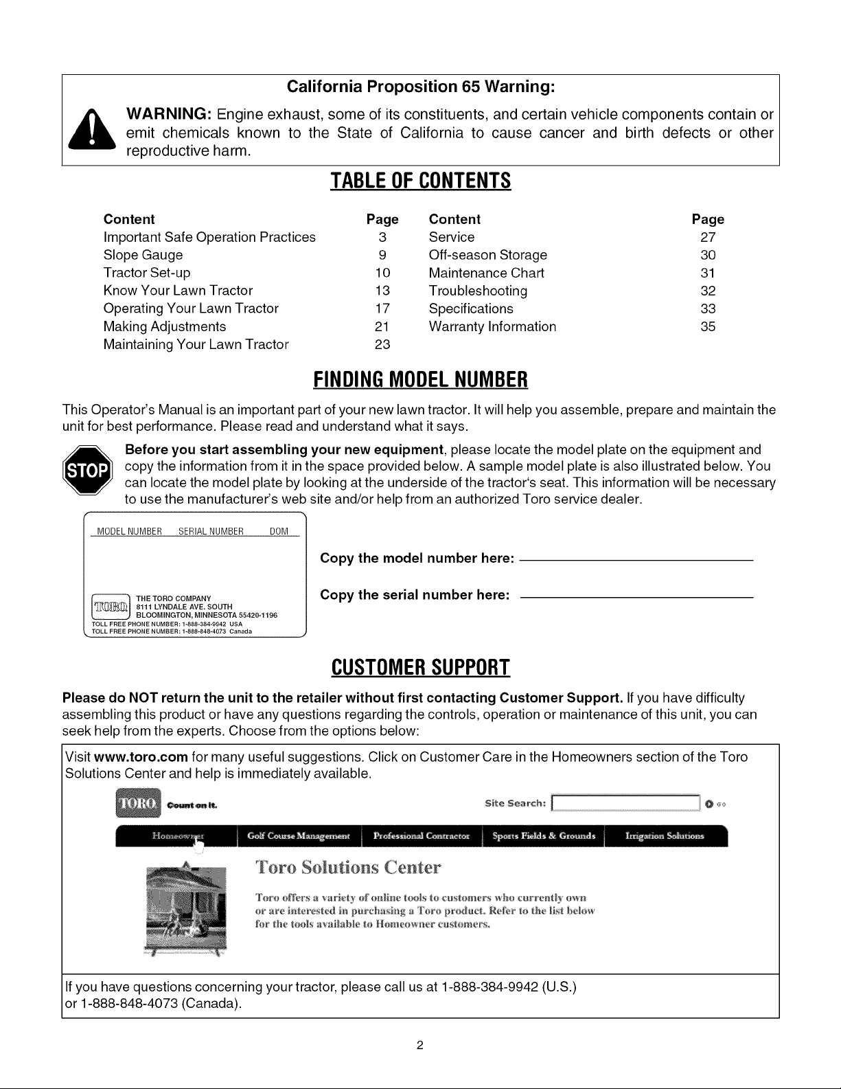
Before you start assembling your new equipment, please locate the model plate on the equipment and
copy the information from it in the space provided below. A sample model plate is also illustrated below. You
can locate the model plate by looking at the underside of the tractor's seat. This information will be necessary
to use the manufacturer's web site and/or help from an authorized Toro service dealer.
MODELNUMBER SERIAL NUMBER DOM
(_ HE TORO COMPANY
8111 LYNDALE AVE. SOUTH
BLOOMINGTON, MINNESOTA 55420-1196
TOLL FREE PHONE NUMBER: 1-888-384-9942 USA
% TOLL FREE PHONE NUMBER: 1-888-848-4073 Canada
Copy the model number here:
Copy the serial number here:
CUSTOMERSUPPORT
Please do NOT return the unit to the retailer without first contacting Customer Support. If you have difficulty
assembling this product or have any questions regarding the controls, operation or maintenance of this unit, you can
seek help from the experts. Choose from the options below:
Visit www.toro.com for many useful suggestions. Click on Customer Care in the Homeowners section of the Toro
Solutions Center and help is immediately available.
N}te Searc;h_ [ @ 8_
If you have questions concerning your tractor, please call us at 1-888-384-9942 (U.S.)
or 1-888-848-4073 (Canada).
SECTION1: IMPORTANTSAFEOPERATIONPRACTICES
WARNING: This symbol points out important safety instructions which, if not followed, could endanger
the personal safety and/or property of yourself and others. Read and follow all instructions in this manual
before attempting to operate this machine. Failure to comply with these instructions may result in personal
injury. When you see this symbol-heed its warning.
DANGER: This machine was built to be operated according to the rules for safe operation in this man-
ual. As with any type of power equipment, carelessness or error on the part of the operator can result in
serious injury. This machine is capable of amputating hands and feet and throwing objects. Failure to
observe the following safety instructions could result in serious injury or death.
WARNING: This unit is equipped with an internal combustion engine and should not be used on or near
any unimproved forest-covered, brush-covered or grass-covered land unless the engine's exhaust system
is equipped with a spark arrester meeting applicable local or state laws (if any). If a spark arrester is used,
it should be maintained in effective working order by the operator. In the State of California the above is
required by law (Section 4442 of the California Public Resources Code). Other states may have similar
laws. Federal laws apply on federal lands.
GENERAL OPERATION
1. Read, understand, and follow all instructions on the
machine and in the manual(s) before attempting to
assemble and operate. Keep this manual in a safe
place for future and regular reference.
2. Be familiar with all controls and their proper
operation. Know how to stop the machine and
disengage PTO/blades quickly.
3. Never allow children under 14 years old to operate
this machine. Children 14 years old and over
should read and understand the operation
instructions and safety rules in this manual and
should be trained and supervised by a parent or
responsible adult.
4. Never allow adults to operate this machine without
proper instruction.
5. To help avoid blade contact or a thrown object
injury, keep bystanders, helpers, children and pets
at least 75 feet from the machine while it is in
operation. Stop machine if anyone enters the area.
6. Thoroughly inspect the area where the equipment
is to be used. Remove all stones, sticks, wire,
bones, toys, and other foreign objects which could
be picked up and thrown by the blade(s). Thrown
objects can cause serious personal injury.
7. Plan your mowing pattern to avoid discharge of
material toward roads, sidewalks, bystanders and
the like. Also, avoid discharging material against a
wall or obstruction which may cause discharged
material to ricochet back toward the operator.
8. Always wear safety glasses or safety goggles
during operation and while performing an
adjustment or repair to protect your eyes. Thrown
objects which ricochet can cause serious injury to
the eyes.
9. Wear sturdy, rough-soled work shoes and close-
fitting slacks and shirts. Loose fitting clothes and
jewelry can be caught in movable parts. Never
operate this machine in bare feet or sandals.
10. Be aware of the mower and attachment discharge
direction and do not point it at anyone. Do not
operate the mower without the discharge cover or
entire grass catcher in its proper place.
11. Do not put hands or feet near rotating parts or
under the cutting deck. Contact with the blade(s)
can amputate hands and feet.
12. A missing or damaged discharge cover can cause
blade contact or thrown object injuries.
13. Stop the blade(s) when crossing gravel drives,
walks, or roads and while not cutting grass.
14. Watch for traffic when operating near or crossing
roadways. This machine is not intended for use on
any public roadway.
15. Do not operate the machine while under the
influence of alcohol or drugs.
16. Mow only in daylight or good artificial light.
17. Never carry passengers.
18. Disengage blade(s) before shifting into reverse.
Back up slowly. Always look down and behind
before and while backing to avoid a back-over
accident.
19. Slow down before turning. Operate the machine
smoothly. Avoid erratic operation and excessive
speed.
20. Disengage blade(s), set parking brake, stop engine
and wait until the blade(s) come to a complete stop
before removing grass catcher, emptying grass,
unclogging chute, removing any grass or debris, or
making any adjustments.
21.Neverleavearunningmachineunattended.
Alwaysturnoffblade(s),placetransmissionin
neutral,setparkingbrake,stopengineandremove
keybeforedismounting.
22.Useextracarewhenloadingorunloadingthe
machineintoatrailerortruck.Thisunitshouldnot
bedrivenupordownramp(s),becausetheunit
couldtipover,causingseriouspersonalinjury.The
unitmustbepushedmanuallyonramp(s)to loador
unloadproperly.
23.Mufflerandenginebecomehotandcancausea
burn.Donottouch.
24.Checkoverheadclearancescarefullybeforedriving
underlowhangingtreebranches,wires,door
openingsetc.,wheretheoperatormaybestruckor
pulledfromtheunit,whichcouldresultinserious
injury.
25.DisengagethePTOandallattachmentclutches,
pressthebrakepedalcompletelyandshiftinto
neutralbeforeattemptingtostartengine.
26.Yourmachineisdesignedtocutnormalresidential
grassofaheightnomorethan10".Donotattempt
to mowthroughunusuallytall,drygrass(e.g.,
pasture)orpilesofdryleaves.Drygrassor leaves
maycontacttheengineexhaustand/orbuildupon
themowerdeckpresentingapotentialfirehazard.
27.Useonlyaccessoriesandattachmentsapproved
forthismachinebythemachinemanufacturer.
Read,understandandfollowallinstructions
providedwiththeapprovedaccessoryor
attachment.
28.Dataindicatesthatoperators,age60yearsand
above,areinvolvedinalargepercentageofriding
mower-relatedinjuries.Theseoperatorsshould
evaluatetheirabilitytooperatetheridingmower
safelyenoughtoprotectthemselvesandothers
fromseriousinjury.
29.If situationsoccurwhicharenotcoveredinthis
manual,usecareandgoodjudgment.Contactan
authorizedToroservicedealerforassistance.
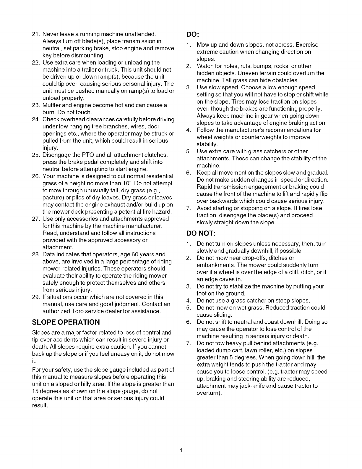
SLOPE OPERATION
Slopes are a major factor related to loss of control and
tip-over accidents which can result in severe injury or
death. All slopes require extra caution. If you cannot
back up the slope or if you feel uneasy on it, do not mow
it.
For your safety, use the slope gauge included as part of
this manual to measure slopes before operating this
unit on a sloped or hilly area. If the slope is greater than
15 degrees as shown on the slope gauge, do not
operate this unit on that area or serious injury could
result.
DO:
1. Mow up and down slopes, not across. Exercise
extreme caution when changing direction on
slopes.
2. Watch for holes, ruts, bumps, rocks, or other
hidden objects. Uneven terrain could overturn the
machine. Tall grass can hide obstacles.
3. Use slow speed. Choose a low enough speed
setting so that you will not have to stop or shift while
on the slope. Tires may lose traction on slopes
even though the brakes are functioning properly.
Always keep machine in gear when going down
slopes to take advantage of engine braking action.
4. Follow the manufacturer's recommendations for
wheel weights or counterweights to improve
stability.
5. Use extra care with grass catchers or other
attachments. These can change the stability of the
machine.
6. Keep all movement on the slopes slow and gradual.
Do not make sudden changes in speed or direction.
Rapid transmission engagement or braking could
cause the front of the machine to lift and rapidly flip
over backwards which could cause serious injury.
7. Avoid starting or stopping on a slope. If tires lose
traction, disengage the blade(s) and proceed
slowly straight down the slope.
DO NOT:
1. Do not turn on slopes unless necessary; then, turn
slowly and gradually downhill, if possible.
2. Do not mow near drop-offs, ditches or
embankments. The mower could suddenly turn
over if a wheel is over the edge of a cliff, ditch, or if
an edge caves in.
3. Do not try to stabilize the machine by putting your
foot on the ground.
4. Do not use a grass catcher on steep slopes.
5. Do not mow on wet grass. Reduced traction could
cause sliding.
6. Do not shift to neutral and coast downhill. Doing so
may cause the operator to lose control of the
machine resulting in serious injury or death.
7. Do not tow heavy pull behind attachments (e.g.
loaded dump cart, lawn roller, etc.) on slopes
greater than 5 degrees. When going down hill, the
extra weight tends to push the tractor and may
cause you to loose control. (e.g. tractor may speed
up, braking and steering ability are reduced,
attachment may jack-knife and cause tractor to
overturn).
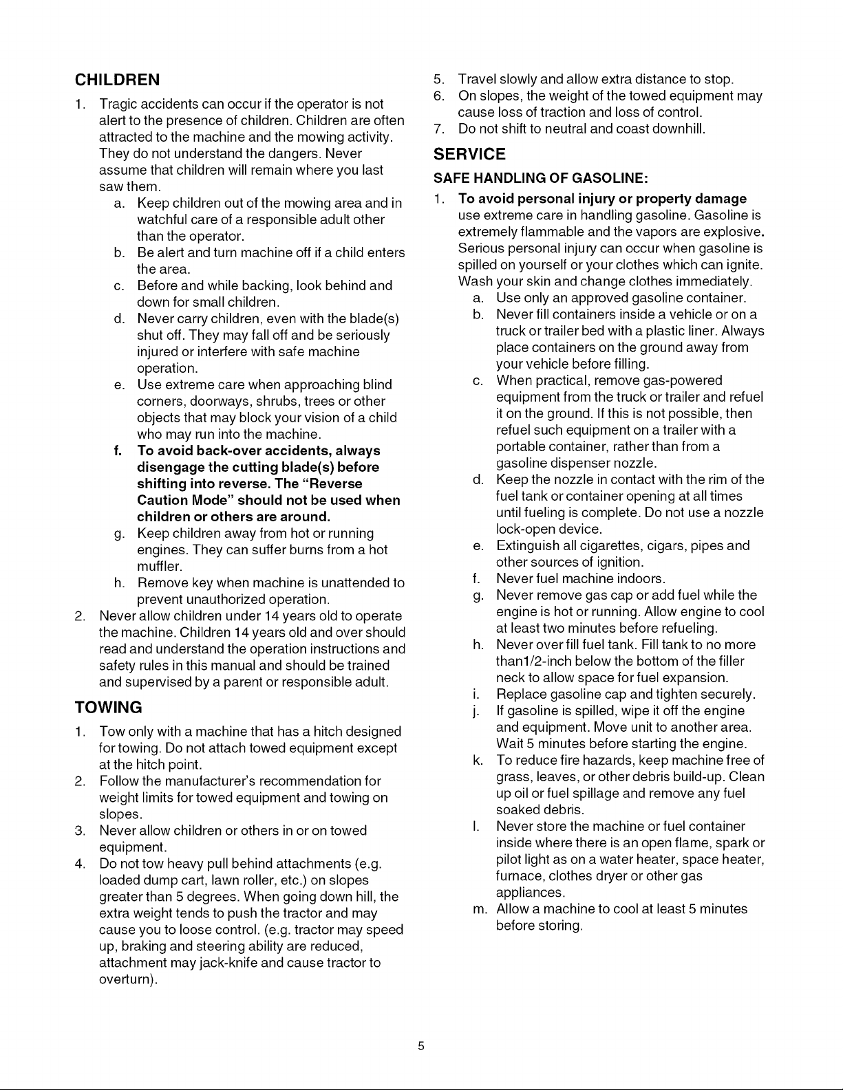
CHILDREN
1. Tragic accidents can occur if the operator is not
alert to the presence of children. Children are often
attracted to the machine and the mowing activity.
They do not understand the dangers. Never
assume that children will remain where you last
saw them.
a. Keep children out of the mowing area and in
watchful care of a responsible adult other
than the operator.
b. Be alert and turn machine off if a child enters
the area.
c. Before and while backing, look behind and
down for small children.
d. Never carry children, even with the blade(s)
shut off. They may fall off and be seriously
injured or interfere with safe machine
operation.
e. Use extreme care when approaching blind
corners, doorways, shrubs, trees or other
objects that may block your vision of a child
who may run into the machine.
f. To avoid back-over accidents, always
disengage the cutting blade(s) before
shifting into reverse. The "Reverse
Caution Mode" should not be used when
children or others are around.
g. Keep children away from hot or running
engines. They can suffer burns from a hot
muffler.
h. Remove key when machine is unattended to
prevent unauthorized operation.
2. Never allow children under 14 years old to operate
the machine. Children 14 years old and over should
read and understand the operation instructions and
safety rules in this manual and should be trained
and supervised by a parent or responsible adult.
TOWING
1. Tow only with a machine that has a hitch designed
for towing. Do not attach towed equipment except
at the hitch point.
2. Follow the manufacturer's recommendation for
weight limits for towed equipment and towing on
slopes.
3. Never allow children or others in or on towed
equipment.
4. Do not tow heavy pull behind attachments (e.g.
loaded dump cart, lawn roller, etc.) on slopes
greater than 5 degrees. When going down hill, the
extra weight tends to push the tractor and may
cause you to loose control. (e.g. tractor may speed
up, braking and steering ability are reduced,
attachment may jack-knife and cause tractor to
overturn).
5. Travel slowly and allow extra distance to stop.
6. On slopes, the weight of the towed equipment may
cause loss of traction and loss of control.
7. Do not shift to neutral and coast downhill.
SERVICE
SAFE HANDLING OF GASOLINE:
To avoid personal injury or property damage
use extreme care in handling gasoline. Gasoline is
extremely flammable and the vapors are explosive.
Serious personal injury can occur when gasoline is
spilled on yourself or your clothes which can ignite.
Wash your skin and change clothes immediately.
a. Use only an approved gasoline container.
b. Never fill containers inside a vehicle or on a
truck or trailer bed with a plastic liner. Always
place containers on the ground away from
your vehicle before filling.
c. When practical, remove gas-powered
equipment from the truck or trailer and refuel
it on the ground. If this is not possible, then
refuel such equipment on a trailer with a
portable container, rather than from a
gasoline dispenser nozzle.
d. Keep the nozzle in contact with the rim of the
fuel tank or container opening at all times
until fueling is complete. Do not use a nozzle
lock-open device.
e. Extinguish all cigarettes, cigars, pipes and
other sources of ignition.
f. Neverfuel machine indoors.
g. Never remove gas cap or add fuel while the
engine is hot or running. Allow engine to cool
at least two minutes before refueling.
h. Never over fill fuel tank. Fill tankto no more
thanl/2-inch below the bottom of the filler
neck to allow space for fuel expansion.
i. Replace gasoline cap and tighten securely.
j. If gasoline is spilled, wipe it off the engine
and equipment. Move unit to another area.
Wait 5 minutes before starting the engine.
k. To reduce fire hazards, keep machine free of
grass, leaves, or other debris build-up. Clean
up oil or fuel spillage and remove any fuel
soaked debris.
I. Never store the machine or fuel container
inside where there is an open flame, spark or
pilot light as on a water heater, space heater,
furnace, clothes dryer or other gas
appliances.
m. Allow a machine to cool at least 5 minutes
before storing.
,
GENERALSERVICE:
1. Never run an engine indoors or in a poorly
ventilated area. Engine exhaust contains carbon
monoxide, an odorless, and deadly gas.
2. Before cleaning, repairing, or inspecting, make
certain the blade(s) and all moving parts have
stopped. Remove the ignition key to prevent
unintended starting.
3. Periodically check to make sure the blades come to
complete stop within approximately five (5)
seconds after operating the blade disengagement
control. If the blades do not stop within the this time
frame, your unit should be serviced professionally
by an authorized Toro service dealer.
4. Check brake operation frequently as it is subjected
to wear during normal operation. Adjust and service
as required.
5. Check the blade(s) and engine mounting bolts at
frequent intervals for proper tightness. Also,
visually inspect blade(s) for damage (e.g.,
excessive wear, bent, cracked).
Replace the blade(s) with the original equipment
manufacturer's (O.E.M.) blade(s) only. Use of parts
which do not meet the original equipment
specifications may lead to improper performance
and compromise safety!
6. Mower blades are sharp. Wrap the blade or wear
gloves, and use extra caution when servicing them.
7. Keep all nuts, bolts, and screws tight to be sure the
equipment is in safe working condition.
8. Never tamper with the safety interlock system or
other safety devices. Check their proper operation
before each use.
9. After striking a foreign object, stop the engine and
remove the ignition key to prevent unintended
starting. Thoroughly inspect the machine for any
damage. Repair the damage before starting and
operating.
10. Never attempt to make adjustments or repairs to
the machine while the engine is running.
11. Grass catcher components and the discharge
cover are subject to wear and damage which could
expose moving parts or allow objects to be thrown.
12. For safety protection, frequently check components
and replace immediately with original equipment
manufacturer's (O.E.M.) parts only. Use of parts
which do not meet the original equipment
specifications may lead to improper performance
and compromise safety!
13. Do not change the engine governor settings or
over-speed the engine. The governor controls the
maximum safe operating speed of the engine.
14. Maintain or replace safety and instruction labels as
necessary (i.e. when scratched, damaged or
missing).
15. Observe proper disposal laws and regulations for
gas, oil, etc. to protect the environment.
WARNING: YOUR RESPONSIBILITY: Restrict the use of this power machine to persons who agree to
read, understand and follow the warnings and instructions in this manual and on the machine.
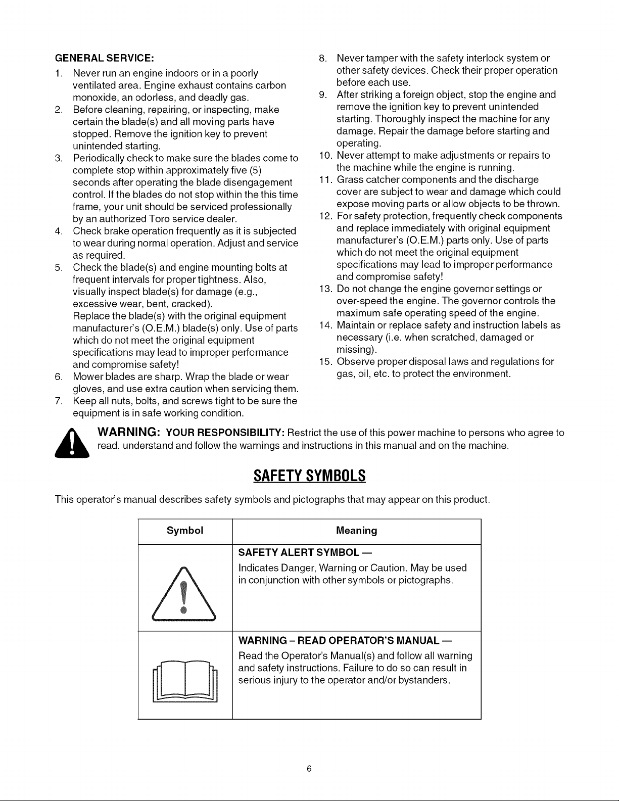
SAFETYSYMBOLS
This operator's manual describes safety symbols and pictographs that may appear on this product.
Symbol Meaning
SAFETY ALERT SYMBOL --
Indicates Danger, Warning or Caution. May be used
in conjunction with other symbols or pictographs.
WARNING - READ OPERATOR'S MANUAL --
Read the Operator's Manual(s) and follow all warning
and safety instructions. Failure to do so can result in
serious injury to the operator and/or bystanders.

SECTION2: SAFETYANDINSTRUCTIONALLABELS
Safety and instructional labels found on your lawn tractor are illustrated below (3/4 actual size). Always follow their
instructions and heed their warnings. If you discover a safety label is scratched, damaged or missing, order a replacement
immediately.
ROTATING BLADES CAUSE
SERIOUS iNJURY OR DEATH
• DONOTM0WWHENCHILDRENOROTHERSARE
AROUND
• HEVERCARRYCHILDREHEVEHWITHBLADE(S)OFF.
• LOOKDOWHAHDDEHIHDBEFOREAHDWHILE
DACI(IH6.
• MOWIHGIHREVERSEISHOTRECOMMEHDED.
®
Part No. 112-1265
PartNo. 112-5958
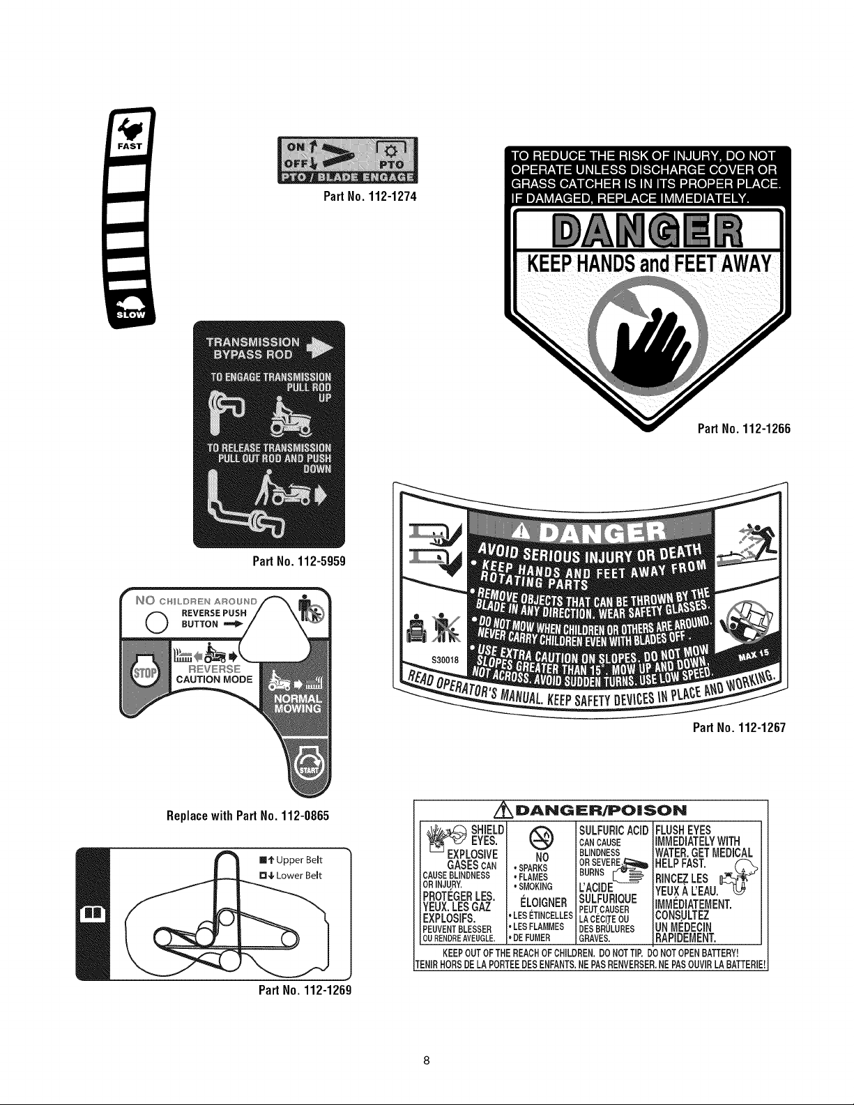
Part No. 112-1274
Pad No. 112-5959
KEEPHANDSandFEETAWAY
Pad No. 112-1266
Q EVERSEPUSH
BUTTON
L KEEPSAFETY
Part No. 112-1267
Replace with Part No. 112-0865
II1_ Upper Belt
D,I, Lower Belt
Pad No. 112-1269
/_ DANGEPJPOISON
SHIELD
EYES.
EXPLOSIVE
GASESCAN
CAUSEBLINDNESS
ORINJURY.
PROTEGERLES.
YEUX.LESGAZ
EXPLOSIFS.
PEUVENTBLESSER
OURENDREAVEUGLE.
SULFURICACID
CANCAUSE
NO BLINDNESS
. SPARKS
,FLAMES
. SMOKING
ELOIGNER SULFURIOUE
PEUTCAUSER
,LESETINCELLESLA CEC[FEOU
,LESFLAMMES DESBRULURES
, DE FUMER GRAVES.
FLUSHEYES
IMMEDIATELYWITH
WATER.GETMEDICAL
HELPFAST. (-__
RINCEZLES _
YEUXA L'EAU. L_#
IMMEDIATEMENT.
CONSULTEZ
UN MEDEClN
RAPIDEMENT.
KEEPOUT OFTHEREACHOF CHILDREN.DO NOTTIP.DO NOTOPENBATTERY!
TENIRHORSDELA PORTEEDESENFANTS.NEPASRENVERSER.NE PASOUVlRLA BATTERIE!
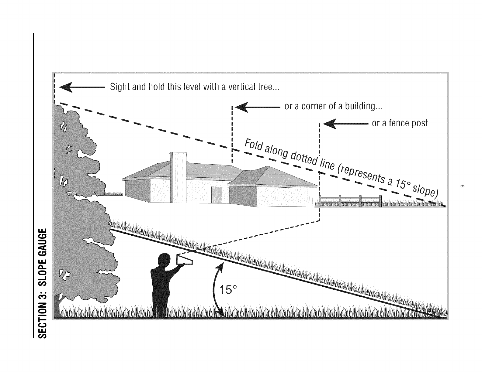
or a corner of a building...
or a fence post
|
|
|
|
15°
Ob
I,,IM
C_
SECTION4: TRACTORSET-UP
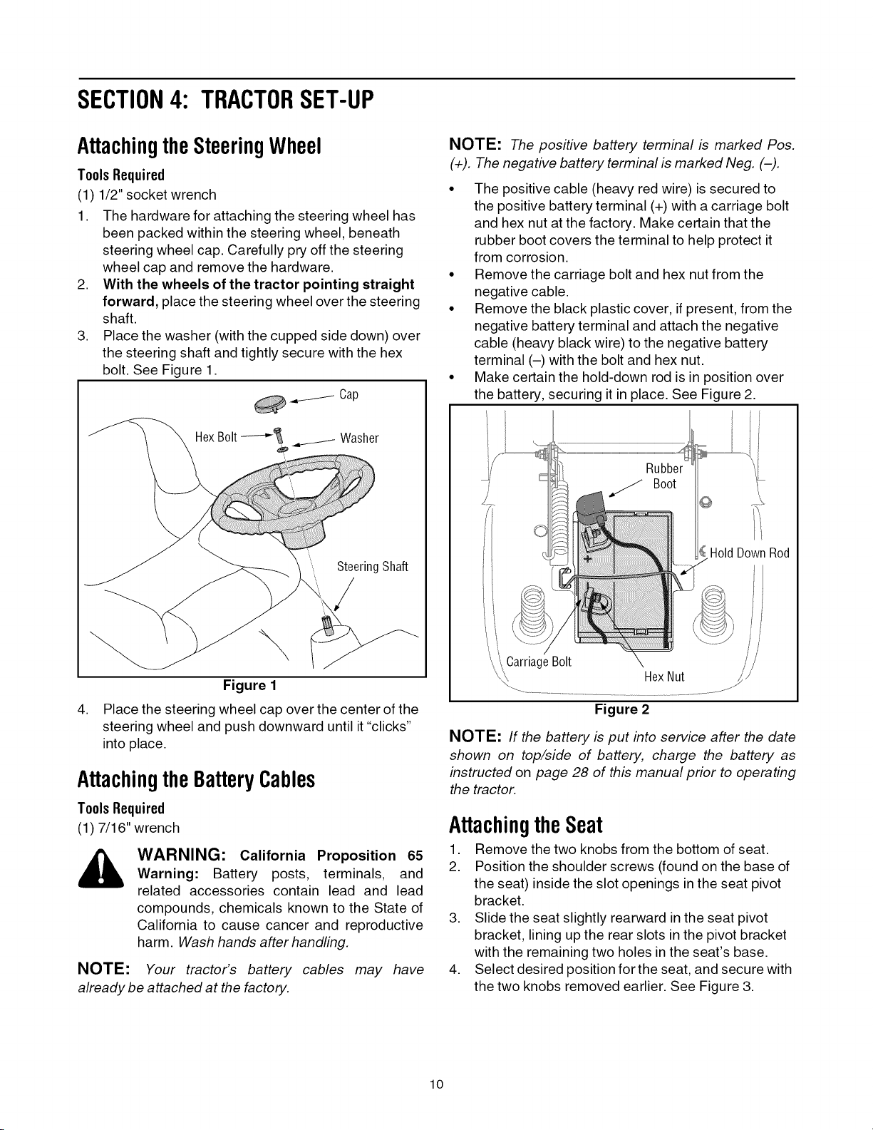
AttachingtheSteeringWheel
ToolsRequired
(1) 1/2" socket wrench
1. The hardware for attaching the steering wheel has
been packed within the steering wheel, beneath
steering wheel cap. Carefully pry off the steering
wheel cap and remove the hardware.
2. With the wheels of the tractor pointing straight
forward, place the steering wheel over the steering
shaft.
3. Place the washer (with the cupped side down) over
the steering shaft and tightly secure with the hex
bolt. See Figure 1.
Cap
........ SteeringShaft
\
,
Figure 1
Place the steering wheel cap over the center of the
steering wheel and push downward until it "clicks"
into place.
AttachingtheBatteryCables
ToolsRequired
(1) 7/16" wrench
WARNING: California Proposition 65
Warning: Battery posts, terminals, and
related accessories contain lead and lead
compounds, chemicals known to the State of
California to cause cancer and reproductive
harm. Wash hands after handling.
NOTE: Your tractor's battery cables may have
already be attached at the factory.
NOTE: The positive battery terminal is marked Pos.
(+). The negative battery terminal is marked Neg. (-).
• The positive cable (heavy red wire) is secured to
the positive battery terminal (+) with a carriage bolt
and hex nut at the factory. Make certain that the
rubber boot covers the terminal to help protect it
from corrosion.
• Remove the carriage bolt and hex nut from the
negative cable.
• Remove the black plastic cover, if present, from the
negative battery terminal and attach the negative
cable (heavy black wire) to the negative battery
terminal (-) with the bolt and hex nut.
• Make certain the hold-down rod is in position over
the battery, securing it in place. See Figure 2.
©
H01dDownRod
CarriageBolt
HexNut
Figure 2
NOTE: If the battery is put into service after the date
shown on top/side of battery, charge the battery as
instructed on page 28 of this manual prior to operating
the tractor.
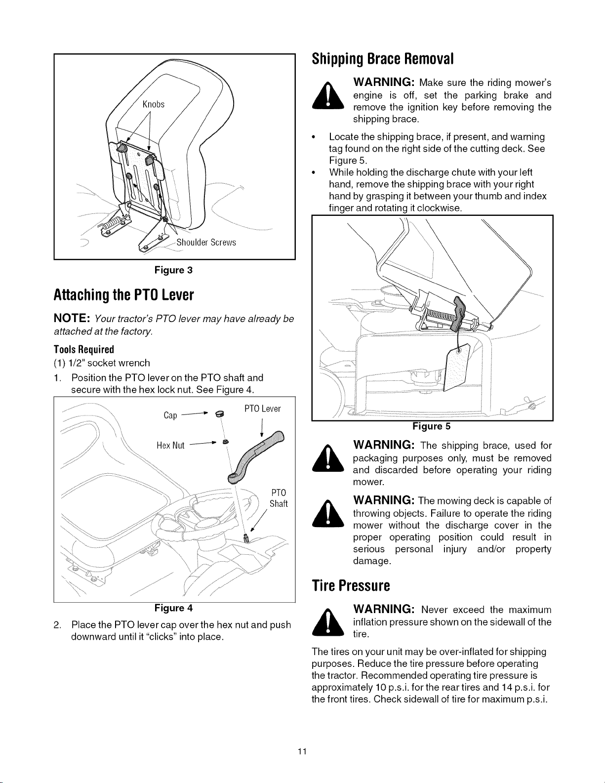
Attachingthe Seat
1. Remove the two knobs from the bottom of seat.
2. Position the shoulder screws (found on the base of
the seat) inside the slot openings in the seat pivot
bracket.
3. Slide the seat slightly rearward in the seat pivot
bracket, lining up the rear slots in the pivot bracket
with the remaining two holes in the seat's base.
4. Select desired position for the seat, and secure with
the two knobs removed earlier. See Figure 3.
10
Screws
Figure 3
AttachingthePTOLever
NOTE: Your tractor's PTO lever may have already be
attached at the factory.
ToolsRequired
(1) 1/2" socket wrench
1. Position the PTO lever on the PTO shaft and
secure with the hex lock nut. See Figure 4.
Cap_
PT0 Lever
HexNut _ _
PTO
Shaft
,
Figure 4
Place the PTO lever cap over the hex nut and push
downward until it "clicks" into place.
ShippingBraceRemoval
_. WARNING: Make sure the riding mower's
engine is off, set the parking brake and
remove the ignition key before removing the
shipping brace.
Locate the shipping brace, if present, and warning
tag found on the right side of the cutting deck. See
Figure 5.
While holding the discharge chute with your left
hand, remove the shipping brace with your right
hand by grasping it between your thumb and index
finger and rotating it clockwise.
Figure 5
WARNING: The shipping brace, used for
packaging purposes only, must be removed
and discarded before operating your riding
mower.
WARNING: The mowing deck is capable of
throwing objects. Failure to operate the riding
mower without the discharge cover in the
proper operating position could result in
serious personal injury and/or property
damage.
Tire Pressure
WARNING: Never exceed the maximum
inflation pressure shown on the sidewall of the
tire.
The tires on your unit may be over-inflated for shipping
purposes. Reduce the tire pressure before operating
the tractor. Recommended operating tire pressure is
approximately 10 p.s.i, for the rear tires and 14 p.s.i, for
the front tires. Check sidewall of tire for maximum p.s.i.
11
SettingtheGaugeWheels
ToolsRequired
(2) 9/16" wrenches
Select the height position of the cutting deck by placing
the deck lift lever in any of the six different cutting height
notches on the right fender.
Adjust the deck wheels so that they are between 1A-inch
and Y2-inchabove the ground as follows.
WARNING: Keep hands and feet away
from the discharge opening of the cutting
deck.
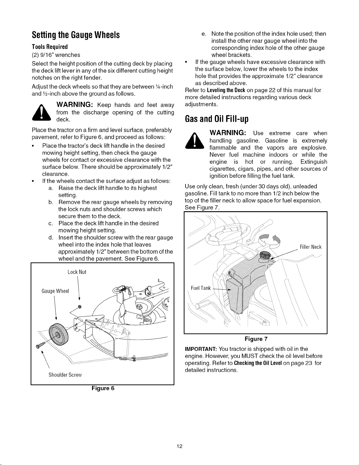
Place the tractor on a firm and level surface, preferably
pavement, refer to Figure 6, and proceed as follows:
• Place the tractor's deck lift handle in the desired
mowing height setting, then check the gauge
wheels for contact or excessive clearance with the
surface below. There should be approximately 1/2"
clearance.
• If the wheels contact the surface adjust as follows:
a. Raise the deck lift handle to its highest
setting.
b. Remove the rear gauge wheels by removing
the lock nuts and shoulder screws which
secure them to the deck.
c. Place the deck lift handle in the desired
mowing height setting.
d. Insert the shoulder screw with the rear gauge
wheel into the index hole that leaves
approximately 1/2" between the bottom of the
wheel and the pavement. See Figure 6.
LockNut
GaugeWheel 1
ShoulderScrew
Figure 6
e. Notethe position of the index hole used; then
install the other rear gauge wheel into the
corresponding index hole of the other gauge
wheel brackets.
• If the gauge wheels have excessive clearance with
the surface below, lower the wheels to the index
hole that provides the approximate 1/2" clearance
as described above.
Refer to LevelingtheDeckon page 22 of this manual for
more detailed instructions regarding various deck
adjustments.
GasandOilFill-up
WARNING: Use extreme care when
handling gasoline. Gasoline is extremely
flammable and the vapors are explosive.
Never fuel machine indoors or while the
engine is hot or running. Extinguish
cigarettes, cigars, pipes, and other sources of
ignition before filling the fuel tank.
Use only clean, fresh (under 30 days old), unleaded
gasoline. Fill tank to no more than 1/2 inch below the
top of the filler neck to allow space for fuel expansion.
See Figure 7.
Filler Neck
FuelTank
\
\\ \
\
\ \ \
\ \\
\\
\
\
\
\
\
\
\
Figure 7
IMPORTANT:You tractor is shipped with oil in the
engine. However, you MUST check the oil level before
operating. Refer to Checkingthe OilLevelon page 23 for
detailed instructions.
12
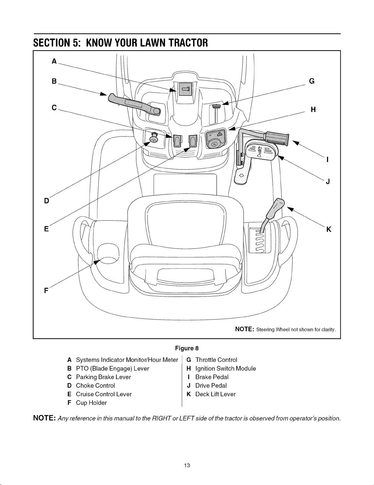
SECTION5: KNOWYOURLAWNTRACTOR
A.
B G
H
J
D
E
F
K
NOTE: Steering Wheel not shown for clarity,
Figure 8
A Systems Indicator Monitor/Hour Meter
B PTO (Blade Engage) Lever
C Parking Brake Lever
D Choke Control
E Cruise Control Lever
F Cup Holder
G Throttle Control
H Ignition Switch Module
I Brake Pedal
J Drive Pedal
K Deck Lift Lever
NOTE: Any reference in this manual to the RIGHT or LEFT side of the tractor is observed from operator's position.
13
ThrottleControlLever
The throttle control lever is
located on the left side of the
tractor's dash panel. This lever
controls the speed of the engine.
When set in a given position, the
throttle will maintain a uniform
engine speed.
IMPORTANT:When operating the
tractor with the cutting deck
engaged, be certain that the
throttle lever is always in the
FAST (rabbit) position.
ChokeControl
The choke control can be found
on the left side of the dash panel
and is activated by pulling the
knob outward. Activating the
choke control closes the choke
plate on the carburetor and aids
in starting the engine. Refer to
StartingThe Engineon page 18 of
this manual for detailed starting
instructions.
BrakePedal
The brake pedal is located on the
right front side of the tractor
above the drive pedal along the
running board. The brake pedal
can be used for sudden stops or
setting the parking brake.
NOTE: The brake pedal must
be fully pressed to activate the
safety interlock switch when
starting the tractor.
DeckLiftLever
Found on your tractor's right
fender, the deck lift lever is used
to change the height of the
cutting deck. To use, move the
lever to the left, then place inthe
notch best suited for your
application.
L
H
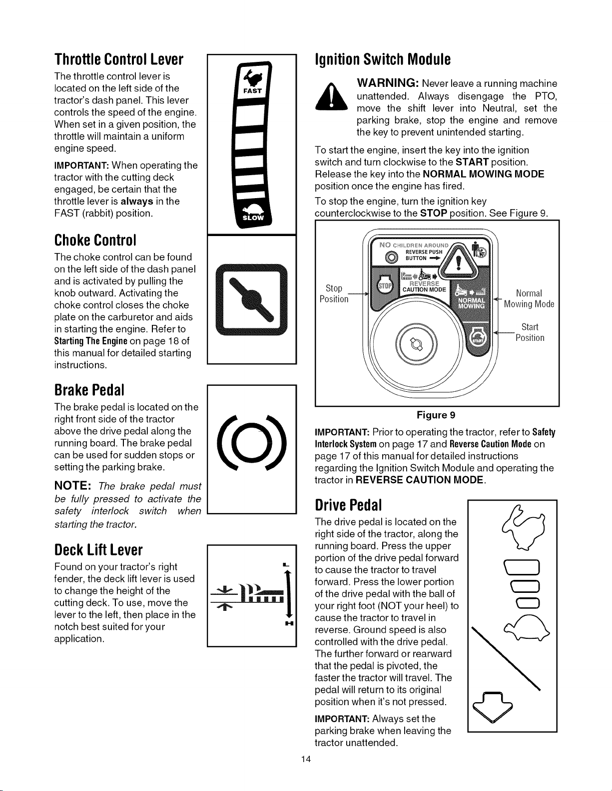
IgnitionSwitchModule
WARNING: Never leave a running machine
unattended. Always disengage the PTO,
move the shift lever into Neutral, set the
parking brake, stop the engine and remove
the key to prevent unintended starting.
To start the engine, insert the key into the ignition
switch and turn clockwise to the START position.
Release the key into the NORMAL MOWING MODE
position once the engine has fired.
To stop the engine, turn the ignition key
counterclockwise to the STOP position. See Figure 9.
Stop
Position
Normal
- Mowing Mode
Start
Position
Figure 9
IMPORTANT:Prior to operating the tractor, refer to Safety
InterlockSystemon page 17 and ReverseCautionModeon
page 17 of this manual for detailed instructions
regarding the Ignition Switch Module and operating the
tractor in REVERSE CAUTION MODE.
DrivePedal
The drive pedal is located on the
right side of the tractor, along the
running board. Press the upper
portion of the drive pedal forward
to cause the tractor to travel
forward. Press the lower portion
of the drive pedal with the ball of
your right foot (NOT your heel) to
cause the tractor to travel in
reverse. Ground speed is also
controlled with the drive pedal.
The further forward or rearward
that the pedal is pivoted, the
faster the tractor will travel. The
pedal will return to its original
position when it's not pressed.
IMPORTANT: Always set the
parking brake when leaving the
tractor unattended.
14
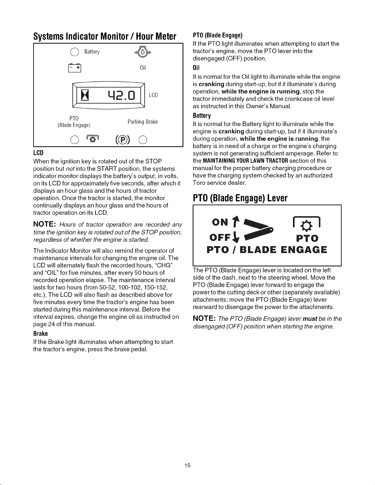
SystemsIndicatorMonitor/ HourMeter
Oil
42.0 I]
PT0
(Blade Engage) Parking Brake
o (®) o
LCD
When the ignition key is rotated out of the STOP
position but not into the START position, the systems
indicator monitor displays the battery's output, in volts,
on its LCD for approximately five seconds, after which it
displays an hour glass and the hours of tractor
operation. Once the tractor is started, the monitor
continually displays an hour glass and the hours of
tractor operation on its LCD.
NOTE: Hours of tractor operation are recorded any
time the ignition key is rotated out of the STOP position,
regardless of whether the engine is started.
The Indicator Monitor will also remind the operator of
maintenance intervals for changing the engine oil. The
LCD will alternately flash the recorded hours, "CHG"
and "OIL" for five minutes, after every 50 hours of
recorded operation elapse. The maintenance interval
lasts for two hours (from 50-52, 100-102, 150-152,
etc.). The LCD will also flash as described above for
five minutes every time the tractor's engine has been
started during this maintenance interval. Before the
interval expires, change the engine oil as instructed on
page 24 of this manual.
Brake
If the Brake light illuminates when attempting to start
the tractor's engine, press the brake pedal.
PTO(Blade Engage)
If the PTO light illuminates when attempting to start the
tractor's engine, move the PTO lever into the
disengaged (OFF) position.
Oil
It is normal for the Oil light to illuminate while the engine
is cranking during start-up, but if it illuminate's during
operation, while the engine is running, stop the
tractor immediately and check the crankcase oil level
as instructed in this Owner's Manual.
Battery
It is normal for the Battery light to illuminate while the
engine is cranking during start-up, but if it illuminate's
during operation, while the engine is running, the
battery is in need of a charge or the engine's charging
system is not generating sufficient amperage. Refer to
the MAINTAININGYOURLAWNTRACTORsection of this
manual for the proper battery charging procedure or
have the charging system checked by an authorized
Toro service dealer.
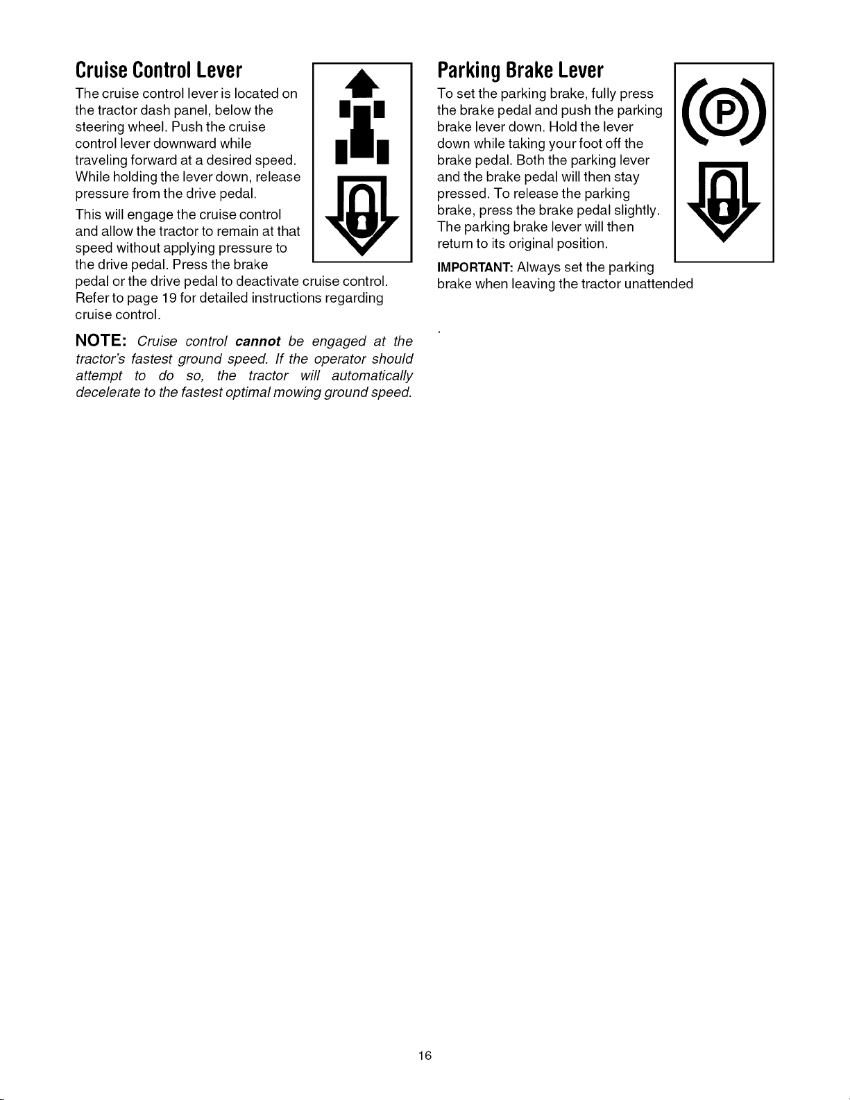
PTO(BladeEngage)Lever
o.1'
OFF
PTO / BLADE
PTO
ENGAGE
The PTO (Blade Engage) lever is located on the left
side of the dash, next to the steering wheel. Move the
PTO (Blade Engage) lever forward to engage the
power to the cutting deck or other (separately available)
attachments; move the PTO (Blade Engage) lever
rearward to disengage the power to the attachments.
NOTE: The PTO (Blade Engage) lever must be in the
disengaged (OFF) position when starting the engine.
15
CruiseControlLever ,A
The cruise control lever is located on
the tractor dash panel, below the _i_1
steering wheel. Push the cruise
control lever downward while
traveling forward at a desired speed.
While holding the lever down, release
pressure from the drive pedal.
This will engage the cruise control
and allow the tractor to remain at that
speed without applying pressure to
the drive pedal. Press the brake
pedal or the drive pedal to deactivate cruise control.
Refer to page 19 for detailed instructions regarding
cruise control.
NOTE: Cruise control cannot be engaged at the
tractor's fastest ground speed. If the operator should
attempt to do so, the tractor will automatically
decelerate to the fastest optimal mowing ground speed.
ParkingBrakeLever
To set the parking brake, fully press
the brake pedal and push the parking
brake lever down. Hold the lever
down while taking your foot off the
brake pedal. Both the parking lever
and the brake pedal will then stay
pressed. To release the parking
brake, press the brake pedal slightly.
The parking brake lever will then
return to its original position.
IMPORTANT:Always set the parking
brake when leaving the tractor unattended
16
SECTION6: OPERATINGYOURLAWNTRACTOR
SafetyInterlockSystem
This tractor is equipped with a safety interlock system
for the protection of the operator. Before each use,
check the safety interlock system for proper operation.
If the interlock system should ever malfunction, do not
operate the tractor. Contact an authorized Toro service
dealer.
• The safety interlock system prevents the engine
from cranking or starting unless the parking brake is
engaged (or the brake pedal fully pressed), and the
PTO (Blade Engage) lever is in the disengaged
(OFF) position. To check for proper operation,
move the PTO (Blade Engage) lever into the
engaged (ON) position and release the parking
brake (or remove your foot from the brake pedal).
Rotate the ignition key into the START position.
The Brake light and the PTO light on the systems
indicator monitor should illuminate, indicating each
control is not in the proper position, and attempts to
start the tractor's engine should fail.
• The engine will automatically shut off if the operator
leaves the seat before engaging the parking brake.
To check for proper operation, start the tractor's
engine, release the parking brake and momentarily
raise yourself from the seat. The engine should
stall.
• The engine will automatically shut off if the operator
leaves the tractor's seat with the PTO (Blade
Engage) lever in the engaged (ON) position,
regardless of whether the parking brake is
engaged. To check for proper operation, start the
tractor's engine, move the PTO (Blade Engage)
lever in the engaged (ON) position and momentarily
raise yourself from the seat. The engine should
stall.
• With the ignition key in the NORMAL MOWING
position, the engine will automatically shut off if the
PTO (Blade Engage) lever is moved into the
engaged (ON) position with the drive pedal in
position for Reverse travel. To check for proper
operation, start the tractor's engine with the ignition
key in the NORMAL MOWING position, move the
PTO (Blade Engage) lever in the engaged (ON)
position, and engage the drive pedal for reverse
travel. The engine should stall.
WARNING: Do not operate the tractor if the
interlock system is malfunctioning. This
system was designed for your safety and
protection.
ReverseCautionMode
The REVERSE CAUTION MODE position of the key
switch module allows the tractor to be operated in
reverse with the blades (PTO) engaged.
IMPORTANT: Mowing in reverse is not recommended.
WARNING: Use extreme caution while
operating the tractor in the REVERSE
CAUTION MODE. Always look down and
behind before and while backing. Do not
operate the tractor when children or others
are around. Stop the tractor immediately if
someone enters the area.
To use the REVERSE CAUTION MODE:
IMPORTANT:The operator MUST be seated in the
tractor seat.
1. Start the engine as previously instructed in this
Operator's Manual.
2. Turn the key from the NORMAL MOWING
(Green) position to the REVERSE CAUTION
MODE (White) position of the key switch module.
See Figure 10.
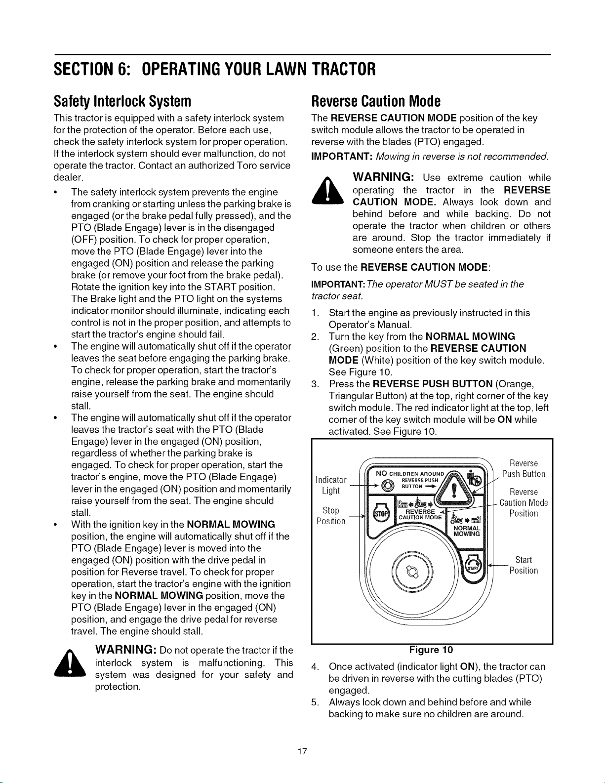
3. Press the REVERSE PUSH BUTTON (Orange,
Triangular Button) at the top, right corner of the key
switch module. The red indicator light at the top, left
corner of the key switch module will be ON while
activated. See Figure 10.
indicator
Light
Stop
Position
NO CHILDREN AROUND
REVERSE PUSH
BUTTON
Reverse
PushButton
Reverse
CautionMode
Position
Start
Position
Figure 10
4. Once activated (indicator light ON), the tractor can
be driven in reverse with the cutting blades (PTO)
engaged.
5. Always look down and behind before and while
backing to make sure no children are around.
17
6. After resuming forward motion, return the key to the
NORMAL MOWING position.
IMPORTANT: The REVERSE CAUTION MODE will
remain activated until:
a. The key is placed in either the NORMAL
MOWING position or STOP position.
b. The operator leaves the seat.
Startingthe Engine
WARNING: Do not operate the tractor if the
interlock system is malfunctioning. This
system was designed for your safety and
protection.
NOTE: Refer to the TRACTORSET-UPon page 10 of this
manual for Gasoline and Oil fill-up instructions.
1. Insert the tractor key into the ignition switch
module.
2. Place the PTO (Blade Engage) lever in the
disengaged (OFF) position.
3. Engage the tractor's parking brake.
4. Activate the choke control.
5. Turn the ignition key clockwise to the START
position. After the engine starts, release the key. It
will return to the NORMAL MOWING position.
IMPORTANT: Do NOT hold the key in the START
position for longer than ten seconds at a time. Doing so
may cause damage to your engine's electric starter.
6. After the engine starts, deactivate the choke
control.
NOTE: Do NOT leave the choke control on while
operating the tractor. Doing so will result in a "rich" fuel
mixture and cause the engine to run poorly.
Stoppingthe Engine
WARNING: If you strike a foreign object,
stop the engine and remove the ignition key.
Thoroughly inspect the machine for any
damage. Repair the damage before restarting
and operating
1. If the blades are engaged, place the PTO/Blade
Engage lever in the disengaged (OFF) position.
2. Position the throttle/choke control between half-
throttle and the FAST (rabbit) position
3. Turn the ignition key counterclockwise to the STOP
position.
4. Remove the key from the ignition switch to prevent
unintended starting.
DrivingTheTractor
WARNING: Avoid sudden starts, ex-
cessive speed and sudden stops.
WARNING: Do not leave the seat of the
tractor without first placing the PTO/Blade
Engage knob in the disengaged (OFF)
position, pressing the brake pedal and
engaging the parking brake. If leaving the
tractor unattended, also turn the ignition key
off and remove the key.
• Briefly press the brake pedal to release the parking
brake. Move the throttle lever into the FAST (rabbit)
position.
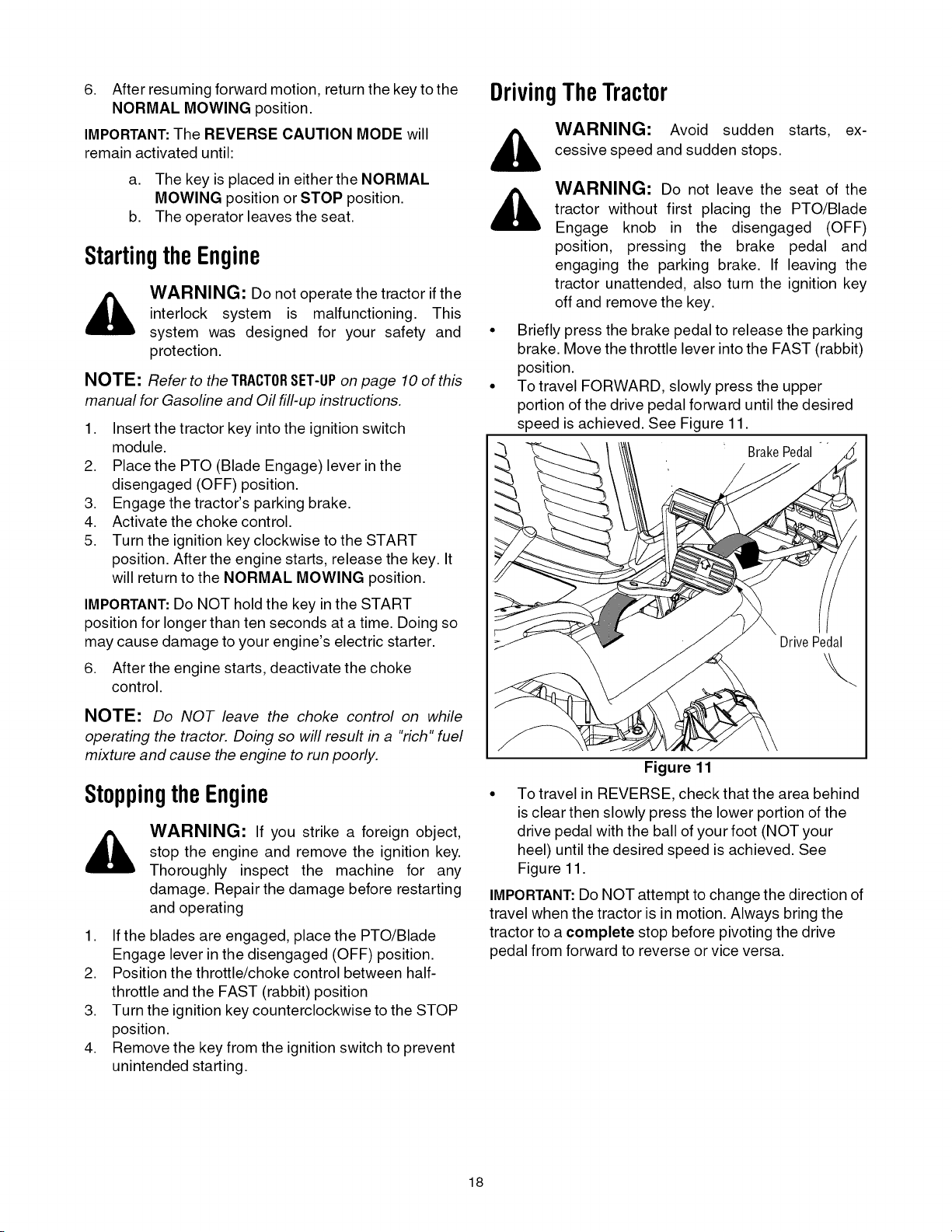
• To travel FORWARD, slowly press the upper
portion of the drive pedal forward until the desired
speed is achieved. See Figure 11.
Brake Pedal
DrivePedal
\
Figure 11
• To travel in REVERSE, check that the area behind
is clear then slowly press the lower portion of the
drive pedal with the ball of your foot (NOT your
heel) until the desired speed is achieved. See
Figure 11.
IMPORTANT: Do NOT attempt to change the direction of
travel when the tractor is in motion. Always bring the
tractor to a complete stop before pivoting the drive
pedal from forward to reverse or vice versa.
18
DrivingOnSlopes
Refer to the SLOPEGAUGEon page 9 to help determine
slopes where you may operate the tractor safely.
_, ARNING: Do not mow on inclines with a
slope in excess of 15 degrees (a rise of
approximately 2-1/2 feet every 10 feet). The
tractor could overturn and cause serious
injury.
• Mow up and down slopes, NEVER across.
• Exercise extreme caution when changing direction
on slopes.
• Watch for holes, ruts, bumps, rocks, or other
hidden objects. Uneven terrain could overturn the
machine. Tall grass can hide obstacles.
• Avoid turns when driving on a slope. If a turn must
be made, turn down the slope. Turning up a slope
greatly increases the chance of a roll over.
• Avoid stopping when driving up a slope. If it is
necessary to stop while driving up a slope, start up
smoothly and carefully to reduce the possibility of
flipping the tractor over backward.
SettingTheCruiseControl
_, ARNING: Never engage cruise control
while traveling in Reverse.
1. Slowly press the drive pedal until the desired speed
is achieved.
2. Lightly press the cruise control lever.
3. While continuing to hold the cruise lever down, lift
your foot from the drive pedal (you should feel the
cruise latch engage).
4. Once engaged, the cruise control lever and the
drive pedal will lock in the "down" position, and the
tractor will maintain the same forward speed.
NOTE: Cruise control can not be set at the tractor's
fastest ground speed. If the operator should attempt to
do so, the tractor will automatically decelerate to the
fastest optimal mowing ground speed.
Disengage the cruise control using one of the following
methods:
• Press the brake pedal to disengage the cruise
control and stop the tractor.
• Lightly press the drive pedal.
To change direction when operating with cruise control,
press the brake pedal to disengage the cruise control
and bring the tractor to a complete stop. Then slowly
press the rear portion of the drive pedal with the ball of
your foot to travel in reverse.
Engagingthe ParkingBrake
To engage the parking brake:
1. Fully press the brake pedal and hold it while gently
pushing the parking brake lever downward.
2. Hold the parking brake lever down while removing
your foot from the brake pedal.
3. Once engaged, the parking brake lever and the
brake pedal will lock in the "down" position.
To disengage the parking brake, slightly press the
brake pedal.
NOTE: The parking brake must be engaged if the
operator leaves the seat with the engine running or the
engine will automatically shut off.
Engagingthe Blades
Engaging the PTO (Blade Engage) transfers power to
the cutting deck or other (separately available)
attachments. To engage the blades, proceed as
follows:
1. Move the throttle/choke control to the FAST (rabbit)
position.
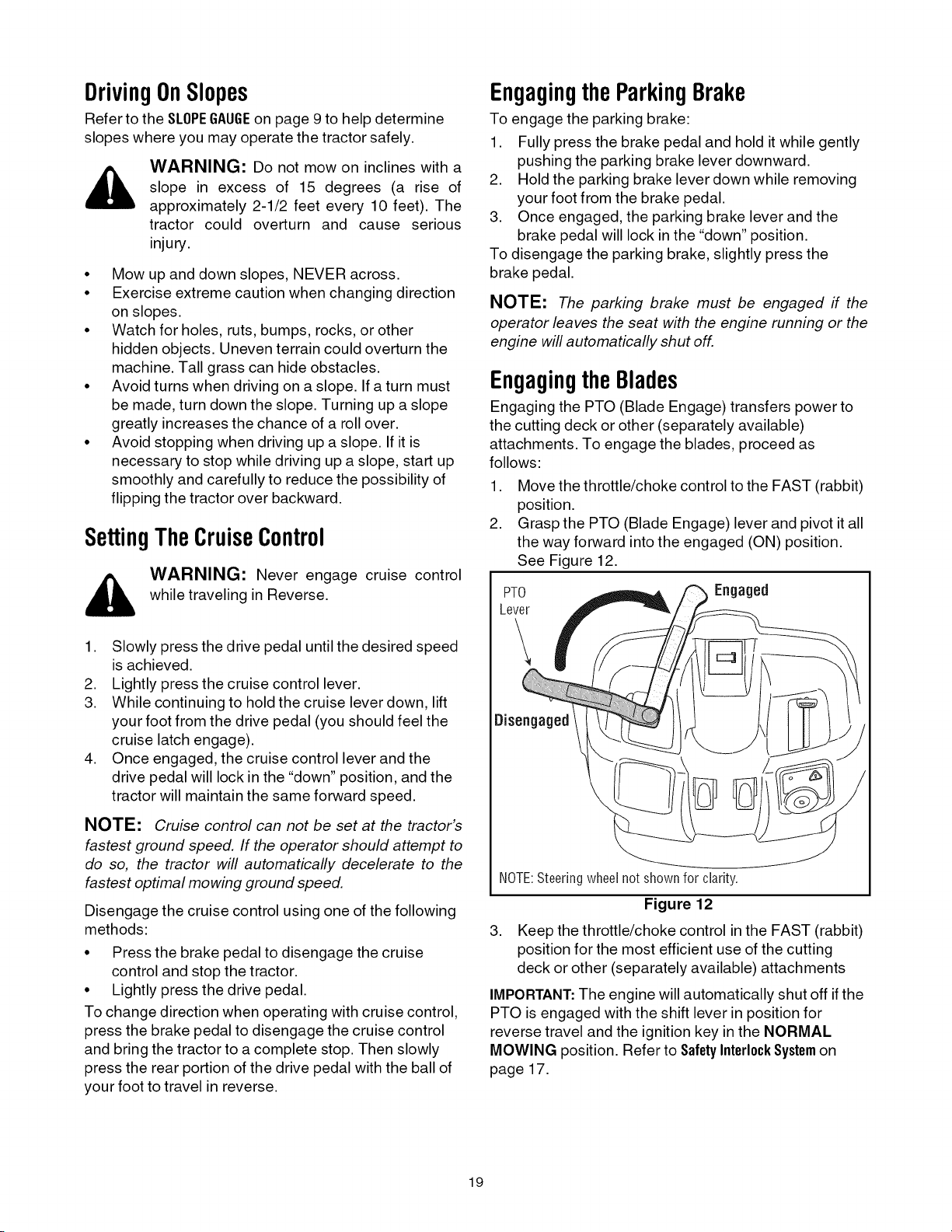
2. Grasp the PTO (Blade Engage) lever and pivot it all
the way forward into the engaged (ON) position.
See Figure 12.
PTO
Lever
\
Engaged
Disengaged
NOTE:Steering wheel not shown for clarity.
Figure 12
3. Keep the throttle/choke control in the FAST (rabbit)
position for the most efficient use of the cutting
deck or other (separately available) attachments
IMPORTANT: The engine will automatically shut off if the
PTO is engaged with the shift lever in position for
reverse travel and the ignition key in the NORMAL
MOWING position. Refer to SafetyInterlockSystemon
page 17.
19
UsingtheDeckLiftLever
To raise the cutting deck, move the deck lift lever to the
left, then place it in the notch best suited for your
application.
Mowing
WARNING: To help avoid blade contact or
a thrown object injury, keep bystanders,
helpers, children and pets at least 75 feet
from the machine while it is in operation. Stop
machine if anyone enters the area.
The following information will be helpful when using the
cutting deck with your tractor.
WARNING: Plan your mowing pattern to
avoid discharge of materials toward roads,
sidewalks, bystanders and the like. Also,
avoid discharging material against a wall or
obstruction which may cause discharged
material to ricochet back toward the operator.
• Do not mow at high ground speed, especially if a
mulch kit or grass collector is installed.
• For best results it is recommended that the first two
laps be cut with the discharge thrown towards the
center. After the first two laps, reverse the direction
to throw the discharge to the outside for the
balance of cutting. This will give a better
appearance to the lawn.
• Do not cut the grass too short. Short grass invites
weed growth and yellows quickly in dry weather.
• Mowing should always be done with the throttle
control in the FAST (rabbit) position.
• Under heavy conditions it may be necessary to go
over the cut area a second time to get a clean cut.
• Do NOT attempt to mow heavy brush and weeds
and extremely tall grass. Your tractor is designed to
mow lawns, NOT clear brush.
• Keep the blades sharp and replace the blades
when worn. Refer to CuttingBladeson page 27 of this
manual for proper blade sharpening instructions.
MovingTheTractorManually
Your tractor's transmission is equipped with a
hydrostatic relief valve for occasions when it is
necessary to move the tractor manually. Opening this
valve permits the fluid in the transmission to bypass its
normal route, allowing the rear tires to "freewheel." To
open the hydrostatic relief valve, proceed as follows:
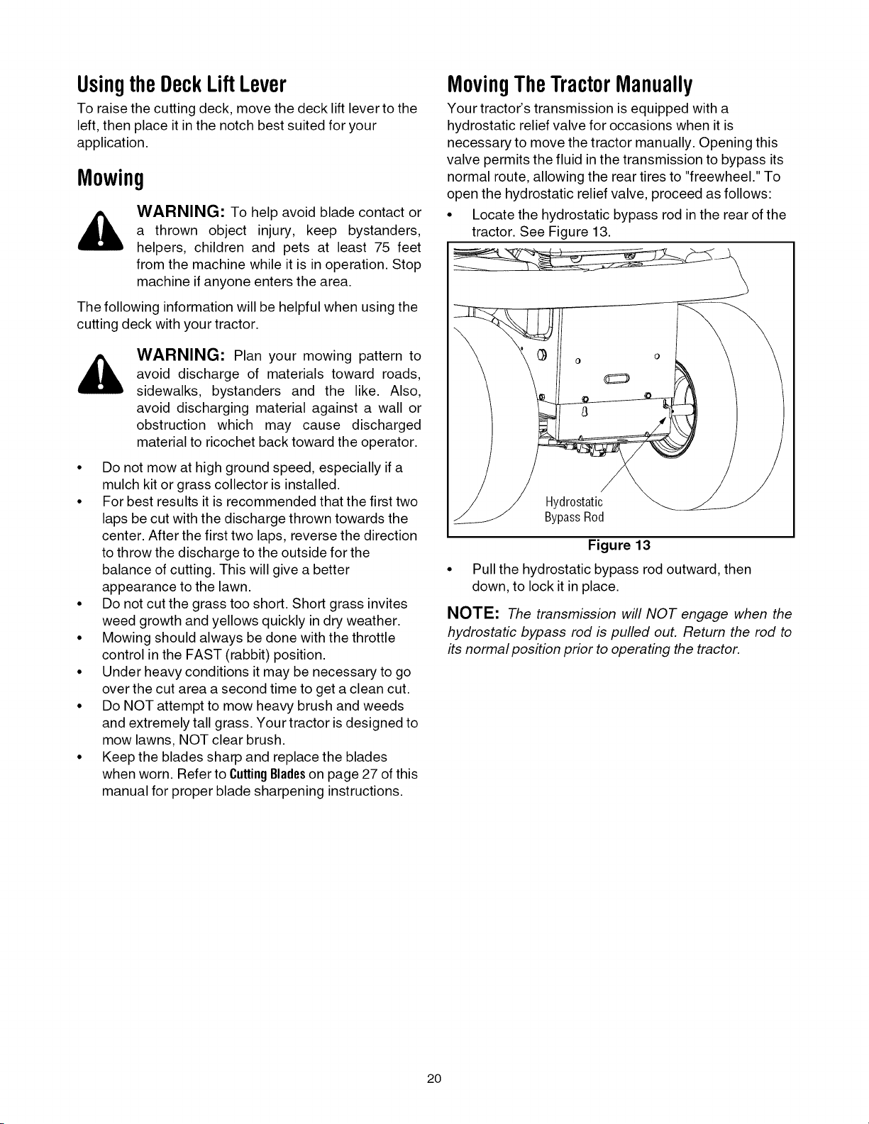
• Locate the hydrostatic bypass rod in the rear of the
tractor. See Figure 13.
Hydrostatic
BypassRod
Figure 13
• Pull the hydrostatic bypass rod outward, then
down, to lock it in place.
NOTE: The transmission will NOT engage when the
hydrostatic bypass rod is pulled out. Return the rod to
its normal position prior to operating the tractor.
20
SECTION7: MAKINGADJUSTMENTS
_, ARNING: Never attempt to make any
adjustments while the engine is running,
LevelingtheDeck
NOTE: Check the tractor's tire pressure before
performing any deck leveling adjustments. Refer to
Tires on page 27 for information regarding tire pressure.
FrontTo Rear
The front of the cutting deck is supported by a stabilizer
bar that can adjusted to level the deck from front to rear.
The front of the deck should be between 1/4-inch and
3/8-inch lower than the rear of the deck. Adjust if
necessary as follows:
1. With the tractor parked on a firm, level surface,
place the deck lift lever in the top notch (highest
position) and rotate the blade nearest the discharge
chute so that it is parallel with the tractor.
2. Measure the distance from the front of the blade tip
to the ground and the rear of the blade tip to the
ground.
3. The first measurement taken should be between
1/4" and 3/8" less than the second measurement.
4. Determine the approximate distance necessary for
proper adjustment and proceed, if necessary, to the
next step.
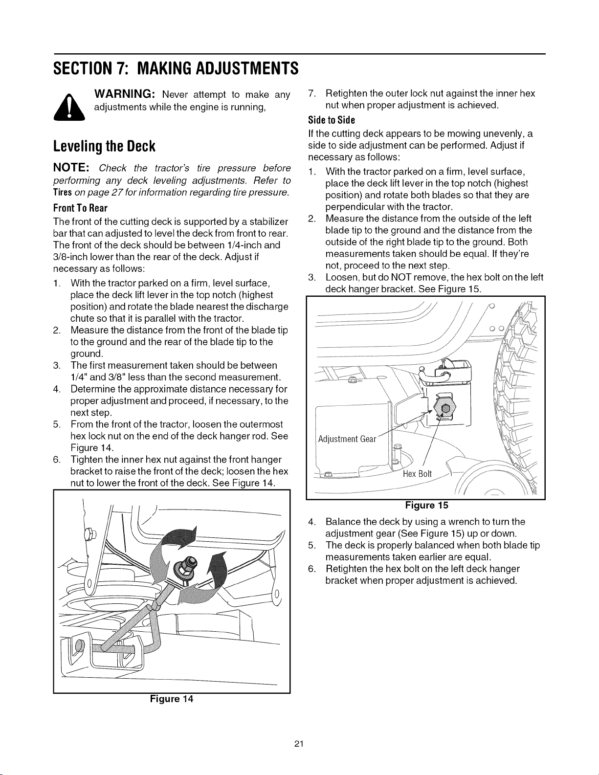
5. From the front of the tractor, loosen the outermost
hex lock nut on the end of the deck hanger rod. See
Figure 14.
6. Tighten the inner hex nut against the front hanger
bracket to raise the front of the deck; loosen the hex
nut to lower the front of the deck. See Figure 14.
7. Retighten the outer lock nut against the inner hex
nut when proper adjustment is achieved.
Sideto Side
If the cutting deck appears to be mowing unevenly, a
side to side adjustment can be performed. Adjust if
necessary as follows:
1. With the tractor parked on a firm, level surface,
place the deck lift lever in the top notch (highest
position) and rotate both blades so that they are
perpendicular with the tractor.
2. Measure the distance from the outside of the left
blade tip to the ground and the distance from the
outside of the right blade tip to the ground. Both
measurements taken should be equal. If they're
not, proceed to the next step.
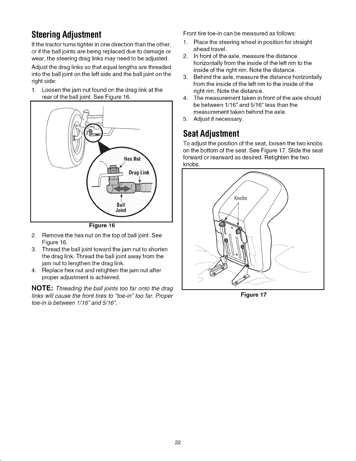
3. Loosen, but do NOT remove, the hex bolt on the left
deck hanger bracket. See Figure 15.
Figure 15
4. Balance the deck by using a wrench to turn the
adjustment gear (See Figure 15) up or down.
5. The deck is properly balanced when both blade tip
measurements taken earlier are equal.
6. Retighten the hex bolt on the left deck hanger
bracket when proper adjustment is achieved.
Figure 14
21
SteeringAdjustment
If the tractor turns tighter in one direction than the other,
or if the ball joints are being replaced due to damage or
wear, the steering drag links may need to be adjusted.
Adjust the drag links so that equal lengths are threaded
into the ball joint on the left side and the ball joint on the
right side:
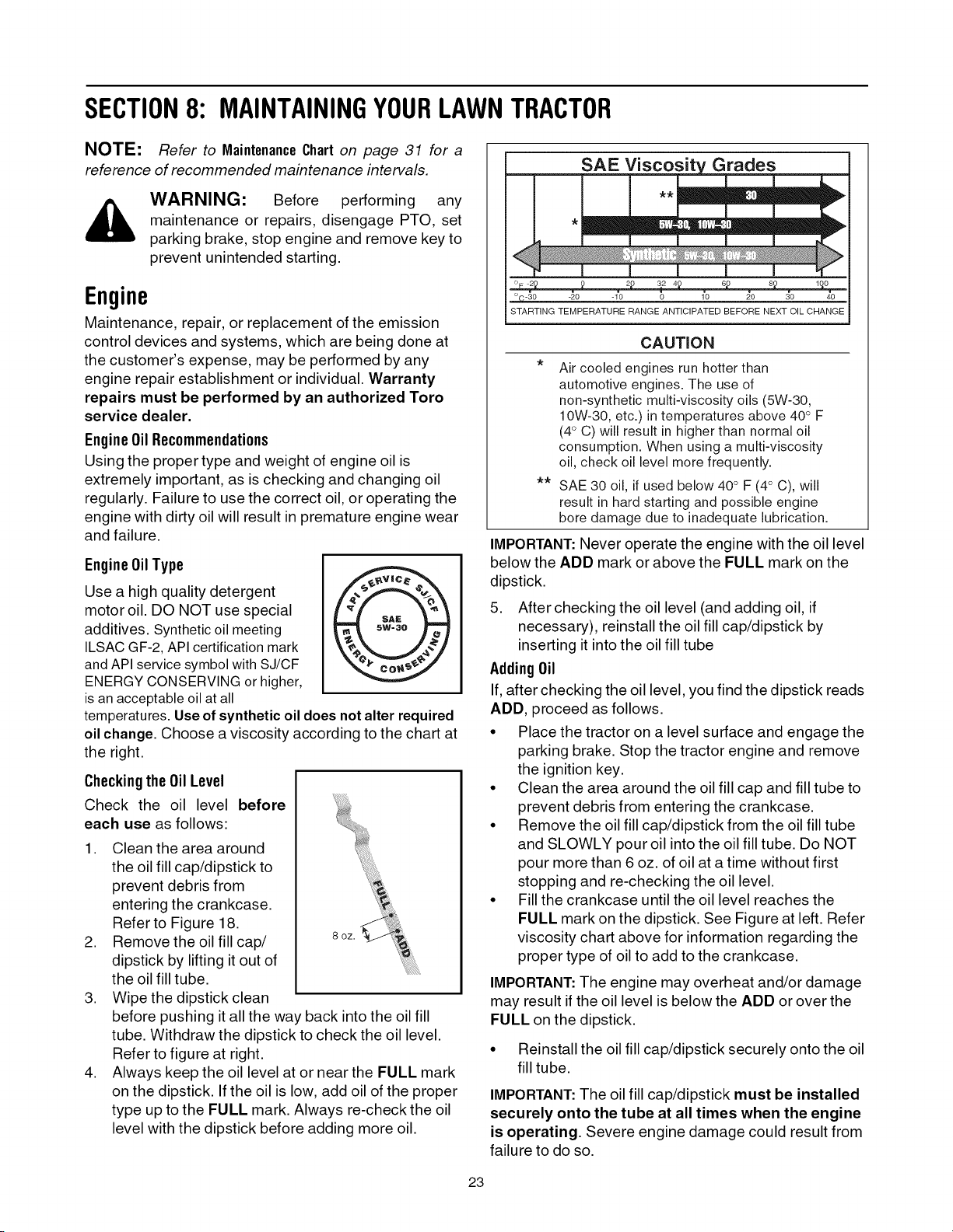
1. Loosen the jam nut found on the drag link at the
rear of the ball joint. See Figure 16.
Front tire toe-in can be measured as follows:
1. Place the steering wheel in position for straight
ahead travel.
2. In front of the axle, measure the distance
horizontally from the inside of the left rim to the
inside of the right rim. Note the distance.
3. Behind the axle, measure the distance horizontally
from the inside of the left rim to the inside of the
right rim. Note the distance.
4. The measurement taken in front of the axle should
be between 1/16" and 5/16" less than the
measurement taken behind the axle.
5. Adjust if necessary.
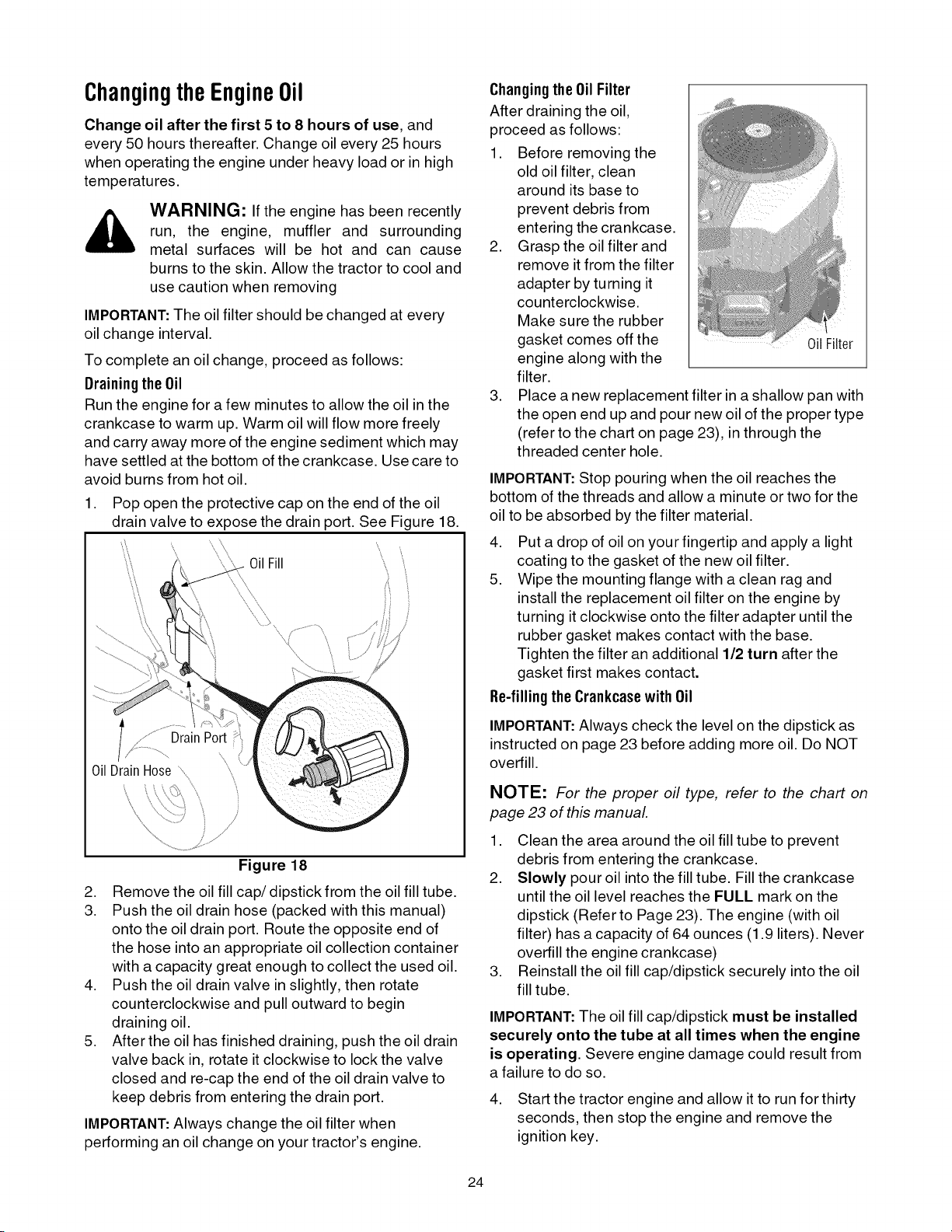
SeatAdjustment
To adjust the position of the seat, loosen the two knobs
on the bottom of the seat. See Figure 17. Slide the seat
forward or rearward as desired. Retighten the two
knobs.
Figure 16
2. Remove the hex nut on the top of ball joint. See
Figure 16.
3. Thread the ball joint toward the jam nut to shorten
the drag link. Thread the ball joint away from the
jam nut to lengthen the drag link.
4. Replace hex nut and retighten the jam nut after
proper adjustment is achieved.
NOTE: Threading the ball joints too far onto the drag
links will cause the front tires to "toe-in" too far. Proper
toe-in is between 1/16" and 5/16".
Figure 17
22
SECTION8: MAINTAININGYOURLAWNTRACTOR
NOTE: Refer to MaintenanceCharton page 31 for a
reference of recommended maintenance intervals.
WARNING: Before performing any
maintenance or repairs, disengage PTO, set
parking brake, stop engine and remove key to
prevent unintended starting.
Engine
Maintenance, repair, or replacement of the emission
control devices and systems, which are being done at
the customer's expense, may be performed by any
engine repair establishment or individual. Warranty
repairs must be performed by an authorized Toro
service dealer.
Engine0il Recommendations
Using the proper type and weight of engine oil is
extremely important, as is checking and changing oil
regularly. Failure to use the correct oil, or operating the
engine with dirty oil will result in premature engine wear
and failure.
Engine0il Type
Use a high quality detergent
motor oil. DO NOT use special
additives. Synthetic oil meeting
ILSAC GF-2, API certification mark
and API service symbol with SJ/CF
ENERGY CONSERVING or higher,
is an acceptable oil at all
temperatures. Use of synthetic oil does not alter required
oil change. Choose a viscosity according to the chart at
the right.
Checkingthe 0il Level
Check the oil level
each use as follows:
1.
before
.
.
.
Clean the area around
the oil fill cap/dipstick to
prevent debris from
entering the crankcase.
Refer to Figure 18.
Remove the oil fill cap/ 8oz.
dipstick by lifting it out of
the oil fill tube.
Wipe the dipstick clean
before pushing it all the way back into the oil fill
tube. Withdraw the dipstick to check the oil level.
Refer to figure at right.
Always keep the oil level at or near the FULL mark
on the dipstick. If the oil is low, add oil of the proper
type up to the FULL mark. Always re-check the oil
level with the dipstick before adding more oil.
SAE Viscosity Grades
__2_ _ 22 32 4# 62 8# 1_0
'_-_0 -_0 40 _ 1"0 _0 _0 _0
STARTING TEMPERATURE RANGE ANTICIPATED BEFORE NEXT OIL CHANGE
CAUTION
Air cooled engines run hotter than
automotive engines. The use of
non-synthetic multi-viscosity oils (5W-30,
10W-30, etc.) in temperatures above 40 ° F
(4° C) will result in higher than normal oil
consumption. When using a multi-viscosity
oil, check oil level more frequently.
SAE 30 oil, if used below 40 ° F (4° C), will
result in hard starting and possible engine
bore damage due to inadequate lubrication.
IMPORTANT: Never operate the engine with the oil level
below the ADD mark or above the FULL mark on the
dipstick.
5. After checking the oil level (and adding oil, if
necessary), reinstall the oil fill cap/dipstick by
inserting it into the oil fill tube
Adding0il
If, after checking the oil level, you find the dipstick reads
ADD, proceed as follows.
• Place the tractor on a level surface and engage the
parking brake. Stop the tractor engine and remove
the ignition key.
• Clean the area around the oil fill cap and fill tube to
prevent debris from entering the crankcase.
• Remove the oil fill cap/dipstick from the oil fill tube
and SLOWLY pour oil into the oil fill tube. Do NOT
pour more than 6 oz. of oil at a time without first
stopping and re-checking the oil level.
• Fill the crankcase until the oil level reaches the
FULL mark on the dipstick. See Figure at left. Refer
viscosity chart above for information regarding the
proper type of oil to add to the crankcase.
IMPORTANT: The engine may overheat and/or damage
may result if the oil level is below the ADD or over the
FULL on the dipstick.
• Reinstall the oil fill cap/dipstick securely onto the oil
fill tube.
IMPORTANT:The oil fill cap/dipstick must be installed
securely onto the tube at all times when the engine
is operating. Severe engine damage could result from
failure to do so.
23
ChangingtheEngineOil
Change oil after the first 5 to 8 hours of use, and
every 50 hours thereafter. Change oil every 25 hours
when operating the engine under heavy load or in high
temperatures.
WARNING: If the engine has been recently
run, the engine, muffler and surrounding
metal surfaces will be hot and can cause
burns to the skin. Allow the tractor to cool and
use caution when removing
IMPORTANT:The oil filter should be changed at every
oil change interval.
To complete an oil change, proceed as follows:
Drainingthe 0il
Run the engine for a few minutes to allow the oil in the
crankcase to warm up. Warm oil will flow more freely
and carry away more of the engine sediment which may
have settled at the bottom of the crankcase. Use care to
avoid burns from hot oil.
,
Pop open the protective cap on the end of the oil
drain valve to expose the drain port. See Figure 18.
0il Fill
Port ?_,
\
OilDrainHose\, '\
/
Figure 18
2. Remove the oil fill cap/dipstick from the oil fill tube.
3. Push the oil drain hose (packed with this manual)
onto the oil drain port. Route the opposite end of
the hose into an appropriate oil collection container
with a capacity great enough to collect the used oil.
4. Push the oil drain valve in slightly, then rotate
counterclockwise and pull outward to begin
draining oil.
5. After the oil has finished draining, push the oil drain
valve back in, rotate it clockwise to lock the valve
closed and re-cap the end of the oil drain valve to
keep debris from entering the drain port.
IMPORTANT: Always change the oil filter when
performing an oil change on your tractor's engine.
Changingthe 0il Filter
After draining the oil,
proceed as follows:
1.
,
,
Before removing the
old oil filter, clean
around its base to
prevent debris from
entering the crankcase.
Grasp the oil filter and
remove it from the filter
adapter by turning it
counterclockwise.
Make sure the rubber
gasket comes off the OilFilter
engine along with the
filter.
Place a new replacement filter in a shallow pan with
the open end up and pour new oil of the proper type
(refer to the chart on page 23), in through the
threaded center hole.
IMPORTANT:Stop pouring when the oil reaches the
bottom of the threads and allow a minute or two for the
oil to be absorbed by the filter material.
4. Put a drop of oil on your fingertip and apply a light
coating to the gasket of the new oil filter.
5. Wipe the mounting flange with a clean rag and
install the replacement oil filter on the engine by
turning it clockwise onto the filter adapter until the
rubber gasket makes contact with the base.
Tighten the filter an additional 1/2 turn after the
gasket first makes contact.
Re-fillingthe Crankcase with Oil
IMPORTANT: Always check the level on the dipstick as
instructed on page 23 before adding more oil. Do NOT
overfill.
NOTE: For the proper oil type, refer to the chart on
page 23 of this manual.
1. Clean the area around the oil fill tube to prevent
debris from entering the crankcase.
2. Slowly pour oil into the fill tube. Fill the crankcase
until the oil level reaches the FULL mark on the
dipstick (Refer to Page 23). The engine (with oil
filter) has a capacity of 64 ounces (1.9 liters). Never
overfill the engine crankcase)
3. Reinstall the oil fill cap/dipstick securely into the oil
fill tube.
IMPORTANT: The oil fill cap/dipstick must be installed
securely onto the tube at all times when the engine
is operating. Severe engine damage could result from
a failure to do so.
4. Start the tractor engine and allow it to run for thirty
seconds, then stop the engine and remove the
ignition key.
24
5. Check the oil level and add oil if necessary. Do not
overfill the engine crankcase.
6. Examine the area around the base of the oil fill
tube, the oil filter adapter, and the oil drain valve for
leaks before operating the tractor.
IMPORTANT: If leaks are present, have your engine
serviced by an authorized Toro service dealer before
operating the tractor.
AirFilter
The engine is equipped with a replaceable, high density
paper air cleaner element and a foam precleaner.
Always examine the air cleaner before starting the
engine. Check for a buildup of dirt and debris around
the air cleaner system. Keep this area clean. Also
check for loose or damaged components. Replace all
bent or damaged air cleaner components.
NOTE: Starting the tractor with loose or damaged air
cleaner components could allow unfiltered air into the
engine causing premature wear and failure.
Service PaperElementand Precleaner
The paper element should be replaced at least once a
season, or every 25 hours of operation. Replace more
frequently if the tractor is operated under extremely
dusty conditions. To replace the paper element,
proceed as follows:
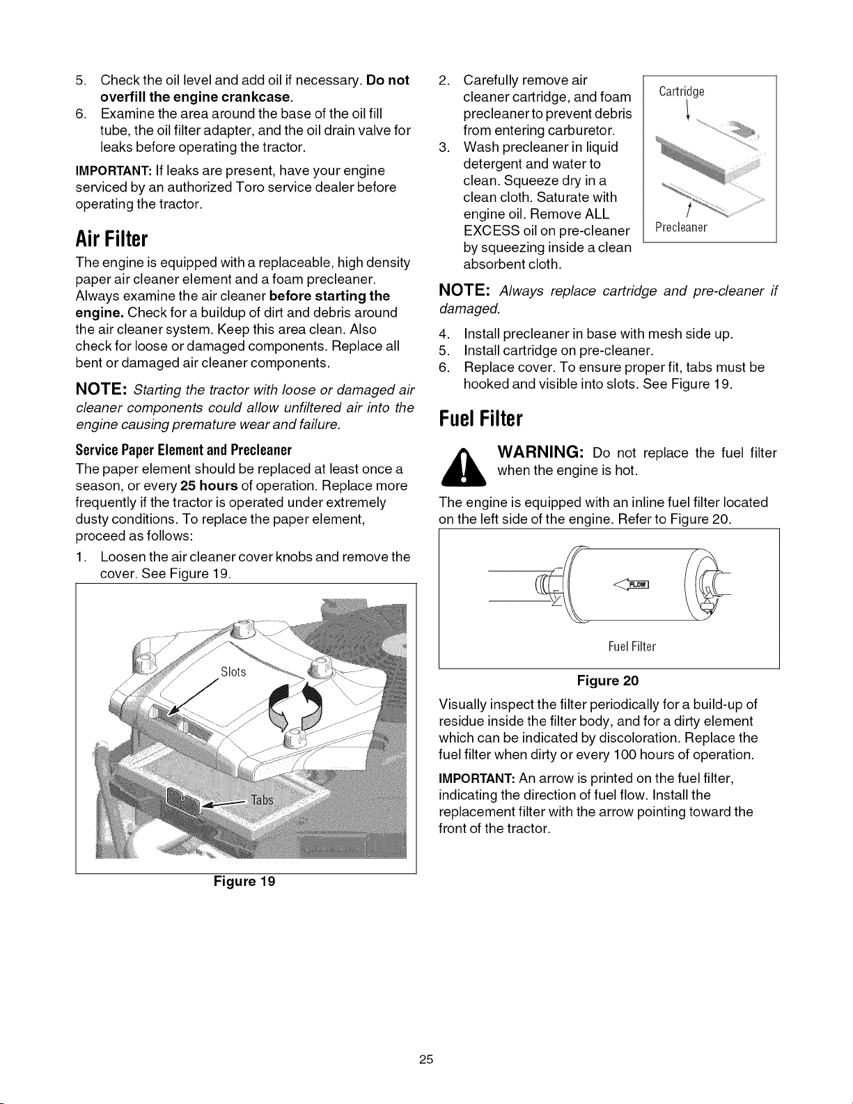
1. Loosen the air cleaner cover knobs and remove the
cover. See Figure 19.
,
,
Carefully remove air
cleaner cartridge, and foam
precleaner to prevent debris
from entering carburetor.
Wash precleaner in liquid
detergent and water to
clean. Squeeze dry in a
clean cloth. Saturate with
engine oil. Remove ALL
EXCESS oil on pre-cleaner
by squeezing inside a clean
absorbent cloth.
Cartridge
Precleaner
NOTE: Always replace cartridge and pre-cleaner if
damaged.
4. Install precleaner in base with mesh side up.
5. Install cartridge on pre-cleaner.
6. Replace cover. To ensure proper fit, tabs must be
hooked and visible into slots. See Figure 19.
FuelFilter
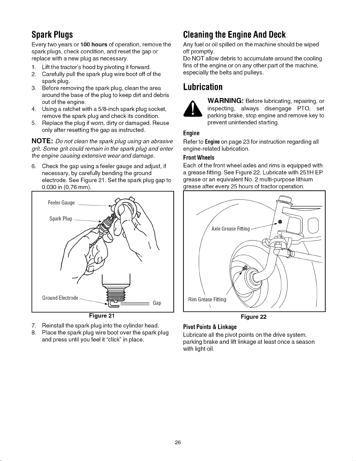
WARNING: Do not replace the fuel filter
when the engine is hot.
The engine is equipped with an inline fuel filter located
on the left side of the engine. Refer to Figure 20.
FuelFilter
Figure 20
Visually inspect the filter periodically for a build-up of
residue inside the filter body, and for a dirty element
which can be indicated by discoloration. Replace the
fuel filter when dirty or every 100 hours of operation.
IMPORTANT:An arrow is printed on the fuel filter,
indicating the direction of fuel flow. Install the
replacement filter with the arrow pointing toward the
front of the tractor.
Figure 19
25
SparkPlugs
Every two years or 100 hours of operation, remove the
spark plugs, check condition, and reset the gap or
replace with a new plug as necessary.
1. Lift the tractor's hood by pivoting it forward.
2. Carefully pull the spark plug wire boot off of the
spark plug.
3. Before removing the spark plug, clean the area
around the base of the plug to keep dirt and debris
out of the engine.
4. Using a ratchet with a 5/8-inch spark plug socket,
remove the spark plug and check its condition.
5. Replace the plug if worn, dirty or damaged. Reuse
only after resetting the gap as instructed.
NOTE: Do not clean the spark plug using an abrasive
grit. Some grit could remain in the spark plug and enter
the engine causing extensive wear and damage.
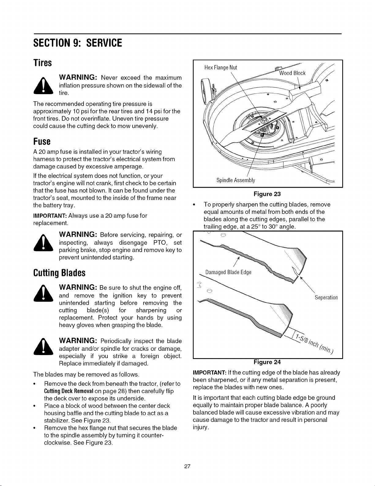
.
Check the gap using a feeler gauge and adjust, if
necessary, by carefully bending the ground
electrode. See Figure 21. Set the spark plug gap to
0.030 in (0.76 mm).
Cleaningthe EngineAndDeck
Any fuel or oil spilled on the machine should be wiped
off promptly.
Do NOT allow debris to accumulate around the cooling
fins of the engine or on any other part of the machine,
especially the belts and pulleys.
Lubrication
WARNING: Before lubricating, repairing, or
inspecting, always disengage PTO, set
parking brake, stop engine and remove key to
prevent unintended starting.
Engine
Refer to Engineon page 23 for instruction regarding all
engine-related lubrication.
Front Wheels
Each of the front wheel axles and rims is equipped with
a grease fitting. See Figure 22. Lubricate with 251H EP
grease or an equivalent No. 2 multi-purpose lithium
grease after every 25 hours of tractor operation.
FeelerGauge
Spark Plug
Ground Electrode
Gap
Figure 21
7. Reinstall the spark plug into the cylinder head.
8. Place the spark plug wire boot over the spark plug
and press until you feel it "click" in place.
RimGreaseFitting
\
Figure 22
PivotPoints& Linkage
Lubricate all the pivot points on the drive system,
parking brake and lift linkage at least once a season
with light oil.
26
SECTION9: SERVICE
Tires
WARNING: Never exceed the maximum
inflation pressure shown on the sidewall of the
tire.
The recommended operating tire pressure is
approximately 10 psi for the rear tires and 14 psi for the
front tires. Do not overinflate. Uneven tire pressure
could cause the cutting deck to mow unevenly.
Fuse
A 20 amp fuse is installed in your tractor's wiring
harness to protect the tractor's electrical system from
damage caused by excessive amperage.
If the electrical system does not function, or your
tractor's engine will not crank, first check to be certain
that the fuse has not blown. It can be found under the
tractor's seat, mounted to the inside of the frame near
the battery tray.
IMPORTANT:Always use a 20 amp fuse for
replacement.
_, ARNING: Before servicing, repairing, or
inspecting, always disengage PTO, set
parking brake, stop engine and remove key to
prevent unintended starting.
CuttingBlades
WARNING: Be sure to shut the engine off,
and remove the ignition key to prevent
unintended starting before removing the
cutting blade(s) for sharpening or
replacement. Protect your hands by using
heavy gloves when grasping the blade.
_, ARNING: Periodically inspect the bladeadapter and/or spindle for cracks or damage,
especially if you strike a foreign object.
Replace immediately if damaged.
The blades may be removed as follows.
• Remove the deck from beneath the tractor, (refer to
CuttingDeckRemovalon page 28) then carefully flip
the deck over to expose its underside.
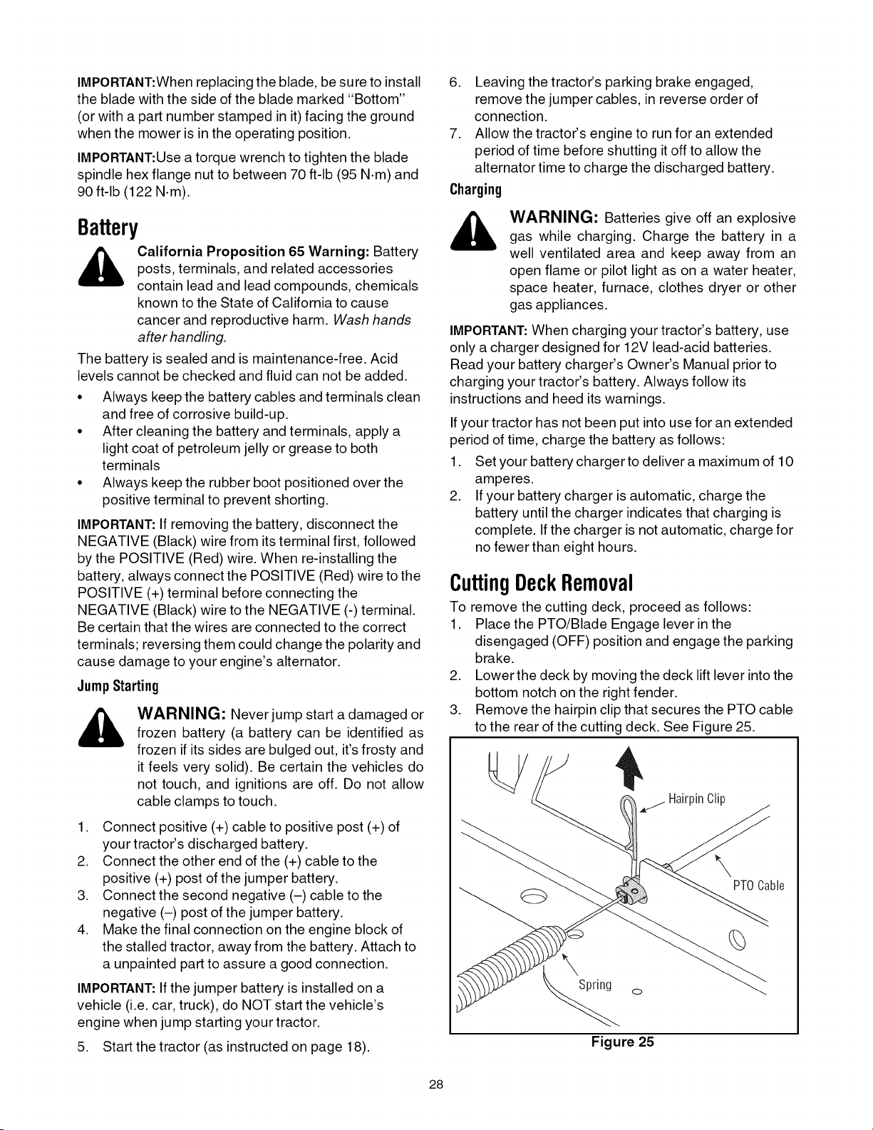
• Place a block of wood between the center deck
housing baffle and the cutting blade to act as a
stabilizer. See Figure 23.
• Remove the hex flange nut that secures the blade
to the spindle assembly by turning it counter-
clockwise. See Figure 23.
HexFlange Nut
Spindle Assembly
Figure 23
To properly sharpen the cutting blades, remove
equal amounts of metal from both ends of the
blades along the cutting edges, parallel to the
trailing edge, at a 25° to 30° angle.
'\\\\
Seperation
Figure 24
IMPORTANT:If the cutting edge of the blade has already
been sharpened, or if any metal separation is present,
replace the blades with new ones.
It is important that each cutting blade edge be ground
equally to maintain proper blade balance. A poorly
balanced blade will cause excessive vibration and may
cause damage to the tractor and result in personal
injury.
27
IMPORTANT:When replacing the blade, be sure to install
the blade with the side of the blade marked "Bottom"
(or with a part number stamped in it) facing the ground
when the mower is in the operating position.
IMPORTANT:Use a torque wrench to tighten the blade
spindle hex flange nut to between 70 ft-lb (95 N.m) and
90 ft-lb (122 N.m).
Battery
California Proposition 65 Warning: Battery
posts, terminals, and related accessories
contain lead and lead compounds, chemicals
known to the State of California to cause
cancer and reproductive harm. Wash hands
after handling.
The battery is sealed and is maintenance-free. Acid
levels cannot be checked and fluid can not be added.
• Always keep the battery cables and terminals clean
and free of corrosive build-up.
• After cleaning the battery and terminals, apply a
light coat of petroleum jelly or grease to both
terminals
• Always keep the rubber boot positioned over the
positive terminal to prevent shorting.
IMPORTANT: If removing the battery, disconnect the
NEGATIVE (Black) wire from its terminal first, followed
by the POSITIVE (Red) wire. When re-installing the
battery, always connect the POSITIVE (Red) wire to the
POSITIVE (+) terminal before connecting the
NEGATIVE (Black) wire to the NEGATIVE (-) terminal.
Be certain that the wires are connected to the correct
terminals; reversing them could change the polarity and
cause damage to your engine's alternator.
Jump Starting
WARNING: Never jump start a damaged or
frozen battery (a battery can be identified as
frozen if its sides are bulged out, it's frosty and
it feels very solid). Be certain the vehicles do
not touch, and ignitions are off. Do not allow
cable clamps to touch.
1. Connect positive (+) cable to positive post (+) of
your tractor's discharged battery.
2. Connect the other end of the (+) cable to the
positive (+) post of the jumper battery.
3. Connect the second negative (-) cable to the
negative (-) post of the jumper battery.
4. Make the final connection on the engine block of
the stalled tractor, away from the battery. Attach to
a unpainted part to assure a good connection.
IMPORTANT: If the jumper battery is installed on a
vehicle (i.e. car, truck), do NOT start the vehicle's
engine when jump starting your tractor.
5. Start the tractor (as instructed on page 18).
6. Leaving the tractor's parking brake engaged,
remove the jumper cables, in reverse order of
connection.
7. Allow the tractor's engine to run for an extended
period of time before shutting it off to allow the
alternator time to charge the discharged battery.
Charging
WARNING: Batteries give off an explosive
gas while charging. Charge the battery in a
well ventilated area and keep away from an
open flame or pilot light as on a water heater,
space heater, furnace, clothes dryer or other
gas appliances.
IMPORTANT: When charging your tractor's battery, use
only a charger designed for 12V lead-acid batteries.
Read your battery charger's Owner's Manual prior to
charging your tractor's battery. Always follow its
instructions and heed its warnings.
If your tractor has not been put into use for an extended
period of time, charge the battery as follows:
1. Set your battery charger to deliver a maximum of 10
amperes.
2. If your battery charger is automatic, charge the
battery until the charger indicates that charging is
complete. If the charger is not automatic, charge for
no fewer than eight hours.
CuttingDeckRemoval
To remove the cutting deck, proceed as follows:
1. Place the PTO/Blade Engage lever in the
disengaged (OFF) position and engage the parking
brake.
2. Lower the deck by moving the deck lift lever into the
bottom notch on the right fender.
3. Remove the hairpin clip that secures the PTO cable
to the rear of the cutting deck. See Figure 25.
HairpinClip
\
Spring
0
\
PTOCable
Figure 25
28
4. Remove the PTO cable and accompanying spring
from the cutting deck.
5. Remove the deck belt from around the tractor's
engine pulley.
6. Looking at the cutting deck from the left side of the
tractor, locate the deck support pin on the rear left
side of the deck.
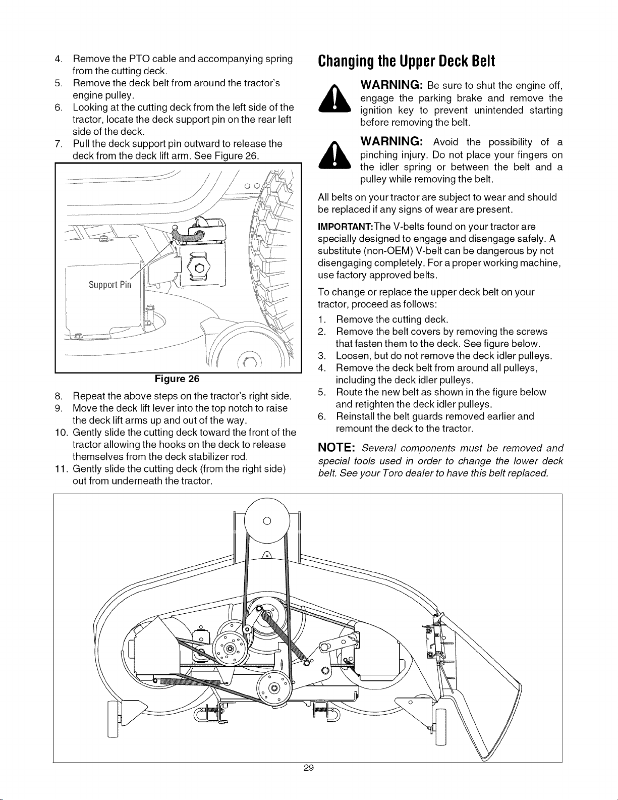
7. Pull the deck support pin outward to release the
deck from the deck lift arm. See Figure 26.
Figure 26
8. Repeat the above steps on the tractor's right side.
9. Move the deck lift lever into the top notch to raise
the deck lift arms up and out of the way.
10. Gently slide the cutting deck toward the front of the
tractor allowing the hooks on the deck to release
themselves from the deck stabilizer rod.
11. Gently slide the cutting deck (from the right side)
out from underneath the tractor.
ChangingtheUpperDeckBelt
WARNING: Be sure to shut the engine off,
engage the parking brake and remove the
ignition key to prevent unintended starting
before removing the belt.
WARNING: Avoid the possibility of a
pinching injury. Do not place your fingers on
the idler spring or between the belt and a
pulley while removing the belt.
All belts on your tractor are subject to wear and should
be replaced if any signs of wear are present.
IMPORTANT:The V-belts found on your tractor are
specially designed to engage and disengage safely. A
substitute (non-OEM) V-belt can be dangerous by not
disengaging completely. For a proper working machine,
use factory approved belts.
To change or replace the upper deck belt on your
tractor, proceed as follows:
1. Remove the cutting deck.
2. Remove the belt covers by removing the screws
that fasten them to the deck. See figure below.
3. Loosen, but do not remove the deck idler pulleys.
4. Remove the deck belt from around all pulleys,
including the deck idler pulleys.
5. Route the new belt as shown in the figure below
and retighten the deck idler pulleys.
6. Reinstall the belt guards removed earlier and
remount the deck to the tractor.
NOTE: Several components must be removed and
special tools used in order to change the lower deck
belt. See your Toro dealer to have this belt replaced.
©
29
SECTION10: OFF-SEASONSTORAGE
Clean and lubricate the tractor as instructed in Section7:
MAINTAININGYOURLAWNTRACTORon page 23 of this
manual before storing for an extended period.
Engine
If the engine will be out of service for two months or
more, use the following storage procedure:
1. Clean the exterior surfaces of the engine.
2. Change the oil and filter while the engine is still
warm from operation. Refer to ChangingEngineOilon
page 24.
3. The fuel system must be completely emptied, or the
gasoline must be treated with a fuel stabilizer such
as STA-BIL®to prevent deterioration. If you choose
to use a stabilizer, follow the manufacturer's
recommendations and add the correct amount for
the capacity of the fuel system. Fill the fuel tank
with clean, fresh gasoline. Run the engine for 2-3
minutes to get stabilized fuel into the carburetor.
To empty the system, run the engine until the tank
and system are empty.
WARNING: Drain fuel only into an
approved container outdoors, away from an
open flame. Allow engine to cool. Extinguish
cigarettes, cigars, pipes, and other sources of
ignition prior to draining fuel.
1. Remove the spark plug. Add one tablespoon of
engine oil into the spark plug hole. Install the plug,
but do not reconnect the plug wire. Crank the
engine two or three revolutions.
2. Store the tractor in a clean, dry place.
WARNING: Never store the machine or
fuel container indoors where there is an open
flame, spark or pilot light such as on water
heater, furnace, clothes dryer or other gas
appliance.
3O

SECTION11: MAINTENANCECHART
Before
Each Use
Every
10 Hours
Every
25 Hours
Every
50 Hours
Every
100 Hours
Every
Season
Prior
to Storing
Check Safety
Interlock System _'
Clean Hood/Dash Louvers _' _'
Check Engine Oil Level _'
Service Air Cleaner _'
Change Engine Oil & Filter _' _'
Clean Battery Terminals _' _'
Lube Front Axles and Rims _' _'
Clean Engine Cooling Fins _' _'
Lube Pedal Pivot Points _' ,_'
Replace Spark Plugs _' _'
31

SECTION12: TROUBLESHOOTING
Trouble
Engine fails to start
Engine runs erratic
Possible Cause(s)
PTO (Blade Engage) lever engaged.
Parking brake not engaged.
Spark plug wire disconnected.
Throttle/choke control not in correct
starting position.
Choke not activated
Fuel tank empty, or stale fuel.
Blocked fuel line.
Faulty spark plug.
Engine flooded.
Unit running with CHOKE activated.
Spark plug wire(s) loose.
Blocked fuel line or stale fuel.
Vent in gas cap plugged.
Water or dirt in fuel system.
Dirty air cleaner.
Engine overheats Engine oil level low.
Air flow restricted.
Engine hesitates at high RPM
Idles poorly
Excessive vibration
Mower will not mulch grass
Spark plug gap too close.
Spark plug fouled, faulty or gap too
wide.
Dirty air cleaner.
Cutting blade loose or unbalanced.
Damaged or bent cutting blade.
Engine speed too low.
Wet grass.
Excessively high grass.
Dull blade.
Uneven cut Deck not balanced properly.
Dull blade.
Uneven tire pressure.
Corrective Action
Place PTO (Blade Engage) lever in (OFF) position.
Engage parking brake.
Connect wire to spark plug.
Move Throttle/Choke Control into CHOKE position.
Move Throttle/Choke Control into CHOKE position.
Fill tank with clean, fresh (less than 30 days old) gas.
Clean fuel line or replace fuel filter.
Clean, adjust gap or replace plug.
Crank engine with throttle in FAST position.
Move Throttle/Choke Control out of CHOKE position.
Connect and tighten spark plug wire(s).
Clean fuel line; fill tank with clean, fresh (less than 30
days old) gasoline. Replace fuel filter, if so equipped.
Clear vent or replace cap if damaged.
Drain fuel tank. Refill with clean, fresh (less than 30
days old) gasoline.
Replace air cleaner paper element or clean foam
precleaner.
Fill crankcase with proper capacity and weight of oil.
Clean grass clippings and debris from around the
engine's cooling fins and blower housing.
Remove spark plug and reset the gap.
Replace spark plug. Set plug gap.
Replace air cleaner element or clean pre-cleaner.
Tighten blade and spindle. Balance blade.
Replace blade.
Place throttle in FAST (rabbit) position.
Do not mow when grass is wet; wait until later to cut.
Mow once at a high cutting height, then mow again at
desired height or make a narrower cutting swath.
Sharpen or replace blade.
Perform side-to-side deck adjustment.
Sharpen or replace blade.
Check tire pressure in all four tires.
32
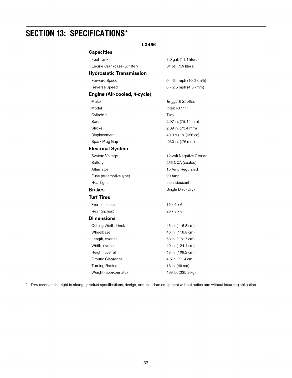
SECTION13: SPECIFICATIONS*
LX466
Capacities
Fuel Tank
Engine Crankcase (w/filter)
Hydrostatic Transmission
Forward Speed
Reverse Speed
Engine (Air-cooled, 4-cycle)
3.0 gal. (11.4 liters)
64 oz. (1.9 liters)
O- 6.4 mph (10.2 km/h)
O- 2.5 mph (4.0 km/h)
Make Briggs & Stratton
Model Intek 407777
Cylinders Two
Bore 2.97 in. (75.44 mm)
Stroke 2.89 in. (73.4 mm)
Displacement 40.0 cu. in. (656 cc)
Spark Plug Gap .030 in. (.76 mm)
Electrical System
System Voltage 12-volt Negative Ground
Battery 235 CCA (sealed)
Alternator 15 Amp Regulated
Fuse (automotive type) 20 Amp
Headlights Incandescent
Brakes Single Disc (Dry)
Turf Tires
Front (inches) 15 x 6 x 6
Rear (inches) 20 x 8 x 8
Dimensions
Cutting Width, Deck 46 in. (116.8 cm)
Wheelbase 46 in. (116.8 cm)
Length, over all 68 in. (172.7 cm)
Width, over all 49 in. (124.4 cm)
Height, over all 43 in. (109.2 cm)
Ground Clearance 4.5 in. (11.4 cm)
Turning Radius 18 in. (46 cm)
Weight (approximate) 498 lb. (225.9 kg)
* Toro reserves the right to change product specifications, design, and standard equipment without notice and without incurring obligation
33
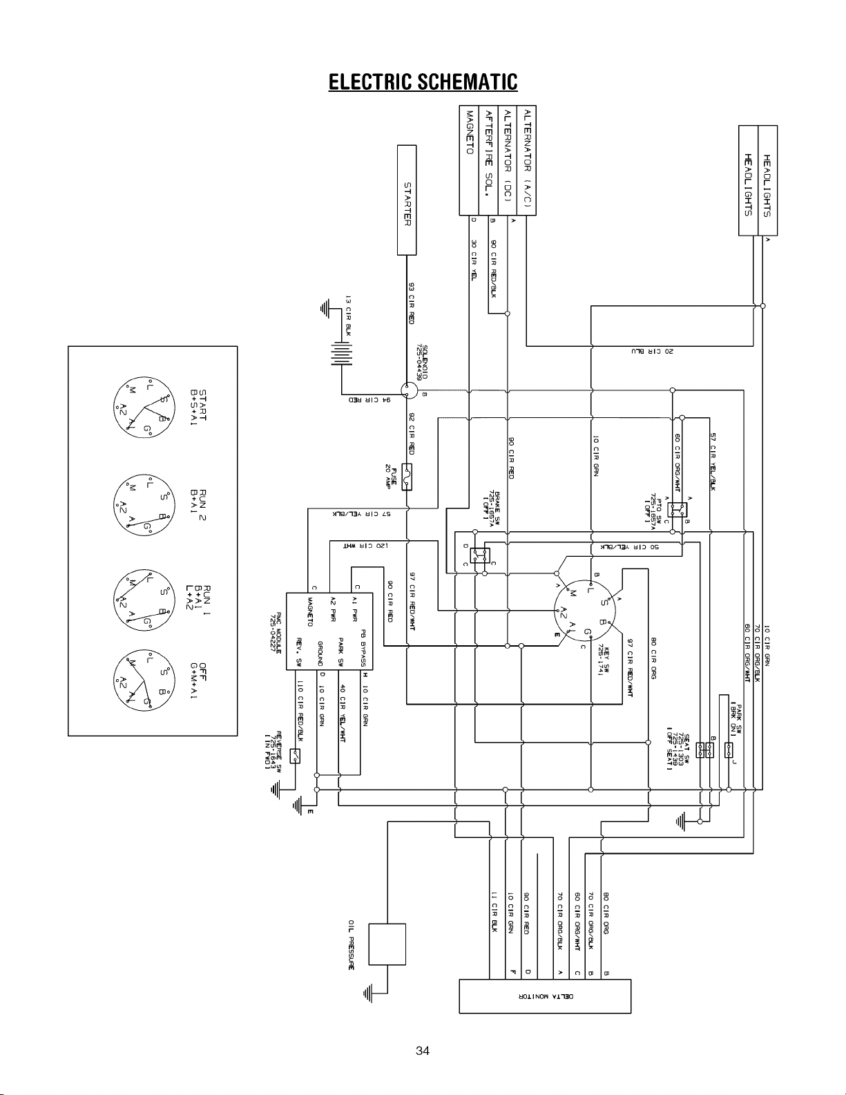
+--I
+_
,>--I
+C
>Z
N
÷÷C
>>Z
630
+.-q
_'-q
+
-_<
r3._,
',IIF
ELECTRICSCHEMATIC
,lll_
ov-]
r-
M
',Ill-
34
CALiFORNiA EMiSSiON CONTROL WARRANTY STATEMENT
YOUR WARRANTY RIGHTS AND OBLiGATiONS
The CaliforniaAir ResourcesBoardandMTDConsumerGroup Inc are pleasedto explainthe evaporativeemissioncontrolsystemwarrantyon your 2007 lawn
mower.In California,new lawnmower mustbe designed,builtand equippedto meetthe State'sstringentanti-smogstandards.MTDConsumerGroupInc must
warrantthe EECSon your lawnmowerfor the periodof time listed below providedthere has been no abuse, neglector impropermaintenanceof your lawnmower.
YourEECSmayincludeparts such asthe carburetor,fuel-injectionsystem,the ignitionsystem,catalyticconverter,fuel tanks,fuel lines,fuel caps, valves,
canisters,filters,vapor hoses,clamps,connectors,and other associatedemission-relatedcomponents.
Where a warrantable condition exists, MTDConsumer Group Inc will repair your lawn mower at no cost toyou includingdiagnosis, partsand labor.
MANUFACTURER'S WARRANTY COVERAGE:
Thisevaporativeemissioncontrol systemis warrantedfor two years. If any evaporativeemission-relatedparton your equipmentis defective,the partwill be
repairedor replacedby MTDConsumerGroupInc.
OWNER'S WARRANTY RESPONSIBILITIES:
Asthe lawn mowerowner,you are responsiblefor performanceof the requiredmaintenancelistedin your owner'smanual. MTDConsumerGroupInc recom-
mendsthat you retain all receiptscoveringmaintenanceon your lawnmower,but MTDConsumerGroupInccannot denywarrantysolelyfor the lackof receipts.
Asthe lawn mowerowner,you shouldhoweverbe awarethat MTDConsumerGroupInc maydeny you warrantycoverageif your lawnmoweror a part has failed
dueto abuse, neglect,or impropermaintenanceor unapprovedmodifications.
Youare responsiblefor presentingyour lawnmowerto MTDConsumerGroupInc'sdistributioncenteror servicecenteras soon asthe problemexists.The
warrantyrepairsshouldbe completedin a reasonableamountof time,not to exceed30 days.If you havea questionregardingyour warrantycoverage,you should
contactthe MTDConsumerGroup IncService Departmentat 1-800-800-7310.
GENERAL EMISSIONS WARRANTY COVERAGE:
MTDConsumerGroup Incwarrantsto the ultimatepurchaserand eachsubsequentpurchaserthat the lawnmower is: Designed,built and equippedso asto
conformwith all applicable regulations;andfree from defectsin materialsand workmanshipthatcausethe failure of a warrantedpartto be identicalin all material
respectsto that part as describedin MTDConsumerGroupInc'sapplicationfor certification.
The warrantyperiodbeginson the datethe lawn moweris deliveredto an ultimatepurchaseror first placedinto service.The warrantyperiodis two years.
Subjectto certain conditionsand exclusionsas stated below,the warrantyon emission-relatedparts is as follows:
1. Any warrantedpart that is not scheduledfor replacementas requiredmaintenanceinthe writteninstructionssupplied, is warrantedfor the warranty period
statedabove. If the partfails duringthe periodof warrantycoverage,the part will be repairedor replacedby MTDConsumerGroupInc accordingto subsection
(4) below.Anysuch part repairedor replacedunderwarrantywillbe warrantedfor the remainderof the period.
2. Any warrantedpart that is scheduledonly for regular inspectioninthe written instructionssuppliedis warrantedfor the warranty periodstated above.Any such
part repairedor replacedunderwarrantywill be warrantedfor the remainingwarrantyperiod.
3. Any warrantedpart that is scheduledfor replacementas requiredmaintenancein the writteninstructionssuppliedis warrantedfor the periodof timebeforethe
first scheduledreplacementdatefor that part. If the part fails beforethe firstscheduledreplacement,the part will be repairedor replacedby MTDConsumer
GroupInc accordingto subsection(4) below.Any such part repairedor replacedunderwarrantywillbe warrantedforthe remainderof the periodprior to the
first scheduledreplacementpointfor the part.
4. Repairor replacementof any warrantedpart underthe warrantyprovisionshereinmust be performedat a warrantystationat no chargeto the owner.
5. Notwithstandingthe provisionsherein,warrantyservicesor repairswill be providedat all of our distributioncentersthat arefranchisedto servicethe subject
enginesor equipment.
6. The lawnmower ownerwill not be chargedfor diagnosticlabor that is directlyassociatedwith diagnosisof a defectke,emission-relatedwarrantedpart,
providedthatsuch diagnostic work is performedat a warrantystation.
7. MTDConsumerGroupInc is liablefor damagesto otherengineorequipmentcomponentsproximatelycausedby a failure underwarrantyof any warranted
part.
8. Throughoutthe lawnmowerwarranty periodstated above,MTDConsumerGroupInc will maintaina supply of warrantedparts sufficientto meet theexpected
demandfor such parts.
9. Any replacementpart may beusedinthe performanceof any warrantymaintenanceor repairsand mustbe providedwithoutchargeto the owner.Such use will
not reducethe warrantyobligationsof MTDConsumerGroupInc.
10.Add-onor modifiedpartsthat are not exemptedby the Air ResourcesBoard may not be used.The use of any non-exemptedadd-onor modifiedparts bythe
ultimatepurchaserwill be groundsfor disallowinga warrantyclaims. MTDConsumerGroupIncwill not be liableto warrantfailuresof warrantedparts caused
bythe use of a non-exemptedadd-onor modifiedpart.
WARRANTED PARTS:
The repairor replacementof anywarrantedpart otherwiseeligiblefor warrantycoveragemay be excludedfrom such warrantycoverageif MTDConsumerGroup
Inc demonstratesthat the lawnmower has been abused,neglected,or improperlymaintained,andthat such abuse, neglect,or impropermaintenancewasthe
directcauseof the need for repairor replacementof the part.That notwithstanding,any adjustmentof a componentthat has afactory installed,and properly
operating,adjustment limitingdevice is still eligiblefor warrantycoverage.Thefollowing emissionwarrantyparts list arecovered: FuelLine,Fuel Line Clamps
The Toro Company
MANUFACTURER'S LIMITED WARRANTY FOR
LAWN & GARDEN TRACTORS
IMPORTANT:To obtainwarrantycoverageownermustpresentan a.
originalproofof purchaseandapplicablemaintenancerecordsto the
servicingdealer.Pleasesee the Operator'sManualfor information
on requiredmaintenanceandserviceintervals, b.
The limitedwarranty set forth below is given by The Toro Company
("Toro") and The Toro Warranty Company, pursuant to an
agreement between them, with respect to new merchandise
purchased or leased and used in the United States and/or its
territories and possessions, and by Toro with respect to new
merchandise purchased or leased and used in Canada and/or its
territories and possession for residential use*.
C.
d.
Torowarrantsthis product(excludingits NormalWear Partsand
Batteriesas describedbelow)againstdefectsin materialand e.
workmanshipfor a periodof two (2) yearscommencingon the
dateof original retailpurchaseor leaseandwill, at its option,repair f.
or replace,free of charge,any partfound to be defectivein materials g.
orworkmanship.
Normal Wear Parts are warranted to be free from defects in material
and workmanship for a period of thirty (30) days from the date of
original purchase or lease. Normal wear parts include, but are not
limited to items such as: belts, blades, blade adapters, grass bags,
rider deck wheels, seats, and tires.
Batteries have a one-year prorated limitedwarranty against defects
in material and workmanship, with 100% replacement during the first
three months. After three months, the battery replacement credit is
based on the months remaining in the twelve (12) month period
dating back to the original date of original sale or lease. Any
replacement battery will be warranted only for the remainder of the
original warranty period.
This limitedwarranty shall only apply if this product has been
operated and maintained in accordance with the Operator's Manual
furnished with the product, and has not been subject to misuse,
abuse, commercial use, neglect, accident, improper maintenance,
alteration, vandalism, theft, fire, water, or damage because of other
peril or natural disaster. Damage resulting from the installation or
use of any part, accessory or attachment not approved by Toro for
use with the product(s) covered by this manual will void your
warranty as to any resulting damage. In addition, Toro may deny
warranty coverage if the hour meter, or any part thereof, is altered,
modified, disconnected or otherwise tampered with.
HOWTO OBTAINSERVICE:Warrantyserviceis available,WITH
PROOFOF PURCHASEAND APPLICABLEMAINTAINCE
RECORDS,throughyourlocalauthorizedservicedealer.To locate
thedealerin your area checkyourYellowPages,or contact;
Customer Care Department,ConsumerDivision
ToroWarrantyCompany
8111LyndaleAvenueSouth
Bloomington,MN55420,1196
In the US 1-888-384-9942(In Canada 1-888-848-4073)
or logon to ourWeb siteat www.toro.com.
Withoutlimitingtheforegoing,this limitedwarrantydoes notprovide
coveragein the followingcases:
The engineor componentpartsthereof. Theseitemsmay
carry a separatemanufacturer'swarranty. Referto
applicablemanufacturer'swarrantyfor terms andconditions.
Routinemaintenanceitemssuchas lubricants,filters, blade
sharpening,tune-ups,brakeadjustments,clutch
adjustments,deck adjustments,andnormaldeteriorationof
theexteriorfinishdue to use or exposure.
Servicecompletedby someoneotherthan an authorized
servicedealer.
Torodoes not extendany warrantyfor productssold or
exportedoutsideof the UnitedStatesand/orCanada,and
their respectivepossessionsandterritories,exceptthose
sold throughToro'sauthorizedchannelsof export
distribution.
Replacementpartsand\oraccessoriesthatare not genuine
Toro parts.
Transportationchargesand servicecalls.
Torodoes notwarrantthis productfor commercialuse*.
There are no impliedwarranties,includingwithout
limitationany impliedwarrantyof merchantabilityor
fitness for a particularpurpose.No warrantiesshallapply
afterthe applicableperiodof expresswrittenwarranty
above.No otherexpresswarrantiesbeyondthose
mentionedabove,givenby anypersonor entity,
includinga dealeror retailer,withrespectto any product,
shallbind Toro. Theexclusiveremedyis repairor
replacementof the productas setforth above.Theterms
of thiswarrantyprovidethe soleand exclusiveremedy
arisingfrom the sale and/orleaseof the products
coveredhereby.Toro shallnot be liablefor any incidental
or consequentiallossordamageincluding,without
limitation,expensesincurredfor substituteor
replacementlawn careservicesor for rentalexpensesto
temporarilyreplacea warrantedproduct.
Somejurisdictionsdo notallowthe exclusionorlimitationof
incidentalor consequentialdamages,or limitationson howlong an
impliedwarrantylasts,so the above exclusionsor limitationsmay
notapplyto you.
In no event shall recovery of any kind be greater than the amount of
the purchase price of the product sold. Alteration of safety
features of the product shall void this warranty. You assume the
risk and liability for loss, damage, or injury to you and your property
and/or to others and their property arising out of the misuse or
inability to use the product.
Thislimitedwarrantyshallnot extendto anyoneotherthan the
originalpurchaserorto the personforwhomit waspurchasedasa
gift.
HOWLOCAL LAWS RELATETOTHISWARRANTY:Thislimited
warrantygivesyou specificlegalrights,and you may alsohaveother
rightsthat varyin differentjurisdictions.
CustomerCare Departmentof the Toro Warranty Company,8111LyndaleAve.South,
Bloomington,MN 55420-1196or call (US)1-888-384-9942,(Canada)1-888-848-4073;www.toro.com
374-0100Rev.C