Loading ...
Loading ...
Loading ...
ASSEMBLY INSTRUCTIONS
STEP 3
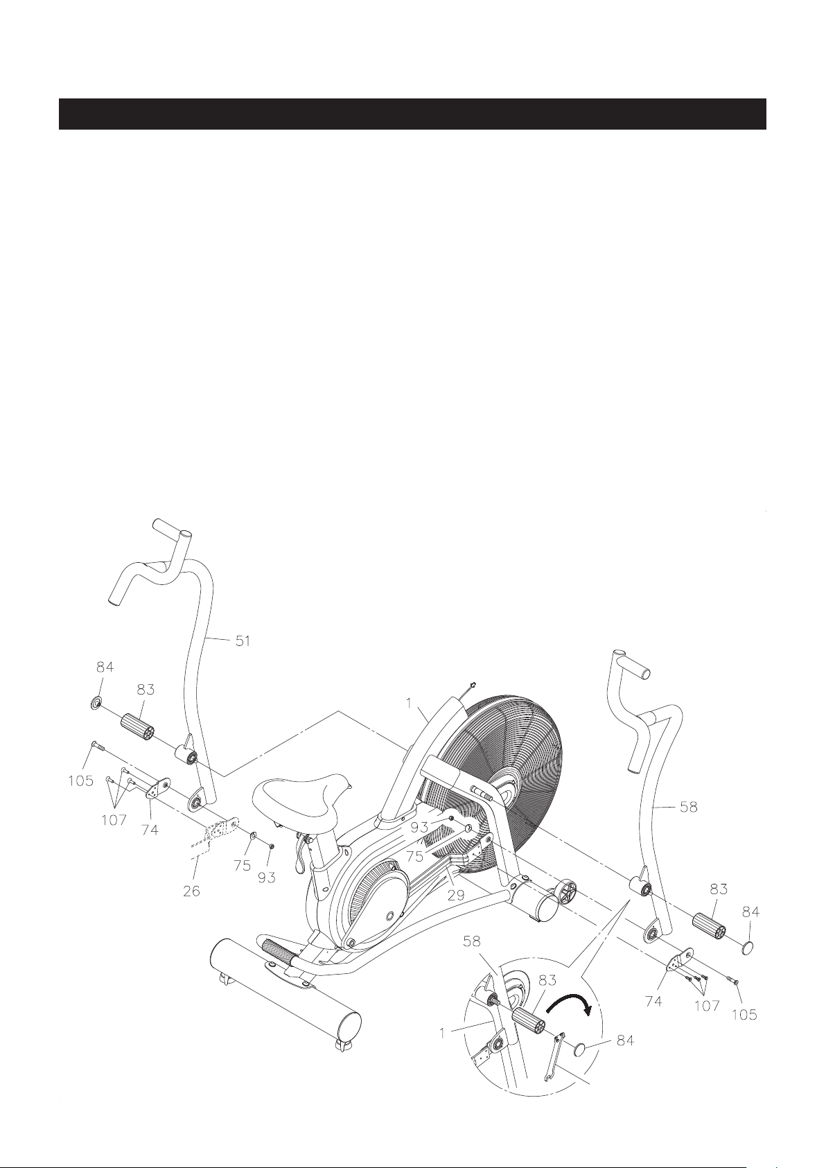
Slide the RIGHT HANDLEBAR(58) onto the shaft on the MAIN FRAME(1), then secure by screwing
the FOOTREST(83) onto the shaft. Refer to the inset drawing. Use the customized wrench to securely
tighten the FOOTREST(83). Press one DECORATIVE PLUG(84) into the end of the FOOTREST(83).
STEP 4
Attach the RIGHT LINKAGE(29) to the lower end of the RIGHT HANDLEBAR(58) with the FIXING
PLATE(74), DISC SPACER(75), FLAT SOCKET HEAD BOLT(M8x1.25x30mm)(105), and NYLOCK
NUT(M8x1.25)(93).
Do Not Securely Tighten The Bolt Until Step 5.
STEP 5
Attach the FIXING PLATE(74) to the RIGHT LINKAGE(29) with FLAT SOCKET HEAD BOLTS
(M6x1x15mm)(107). Securely Tighten All Of The Bolts.
Do the same way from Step 3 to Step 5 to attach the LEFT HANDLEBAR(51), and connect the LEFT
LINKAGE(26).
8
Customized Wrench
Loading ...
Loading ...
Loading ...