Loading ...
Loading ...
Loading ...
page 9
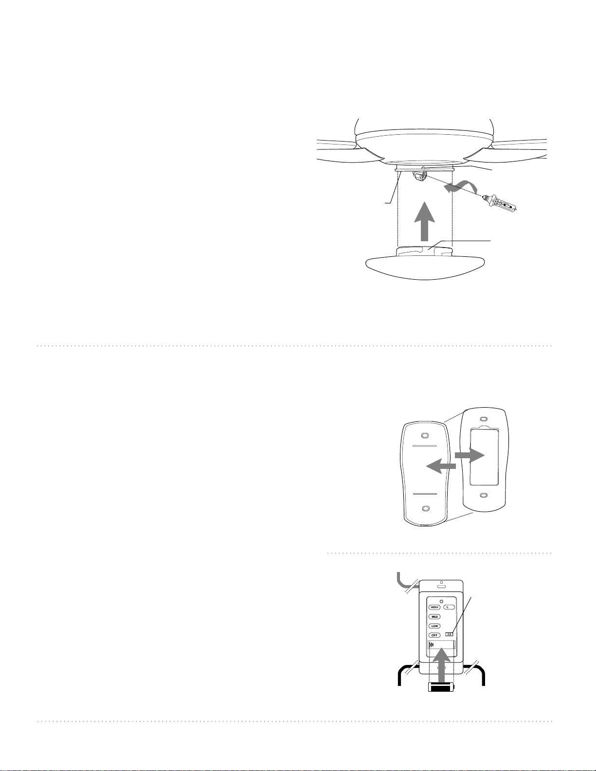
9. Light Kit Assembly. (cont.)
Install one 75 watt max. halogen bulb, type
JD E11 (included).
Tip: Do not touch glass portion of bulb with
fingers or hands. Oil from skin can cause bulb to
overheat and go out prematurely. Use cardboard
box or foam wrapping bulb was packed with to
layer around glass portion of bulb.
Locate grooves on glass shade and align with
nodules on inside of light kit fitter. Push up
gently on glass shade. Turn glass shade in a
clockwise direction until it slides into place. Pull
down VERY GENTLY on glass shade to make sure
that glass shade is secure.
IMPORTANT: When you need to replace the
bulb, please allow bulb and glass shade to cool
down before touching, keeping in mind not to
touch the bulb itself as described above
(see "Tip").
glass shade
motor
housing
nodule
groove
bulb
light kit
fitter
10. Handheld Remote Control Assembly.
IN ORDER TO USE THE HANDHELD REMOTE
CONTROL, PLEASE CONTINUE WITH SECTION 10
for remote control assembly instructions. If you
have already installed the wall control but do not
wish to use the handheld remote control, please
proceed to Section 11.
Gently pull on remote control cover to separate
top and bottom parts. [Refer to diagram 1.]
In order to use wall control as a handheld
remote control, cut each wire on wall control
(that was not previously used)--use wire cutters
to cut off each wire as close to the wall control
as possible. [Refer to diagram 2.]
Install one 12-volt battery (included) in wall
control. [Refer to diagram 2.]
The dimmer switch (labeled DIM and ON) has
been pre-set to the "ON" position (DIM). If you
do not wish to have dimming capability, please
move the switch to the "OFF" position (ON).
[Refer to diagram 2.]
(top)
(bottom)
remote control
cover
diagram 1
dimmer
switch
wall control
wire
wire
wire
12V battery
11
-
DIM ON
diagram 2
Loading ...
Loading ...
Loading ...