Loading ...
Loading ...
Loading ...
INSTALLATION
Check the appliance is electrically safe when you have nished.
30
ArtNo.280-0045 Burner Knob
A
L1
L2
P
9
L3
A
L1
L2
P
9
L3
A
L1
L2
P
9
L3
A
L1
L2
P
9
L3
A
L1
L2
P
9
L3
M
150°
200°
250°
300°
350°
400°
450°
F°
ArtNo.280-0053 Door Knob Screw to Door
A
L1
L2
P
9
L3
A
L1
L2
P
9
L3
A
L1
L2
P
9
L3
A
L1
L2
P
9
L3
A
L1
L2
P
9
L3
M
150°
200°
250°
300°
350°
400°
450°
F°
150°
200°
250°
300°
350°
400°
450°
F°
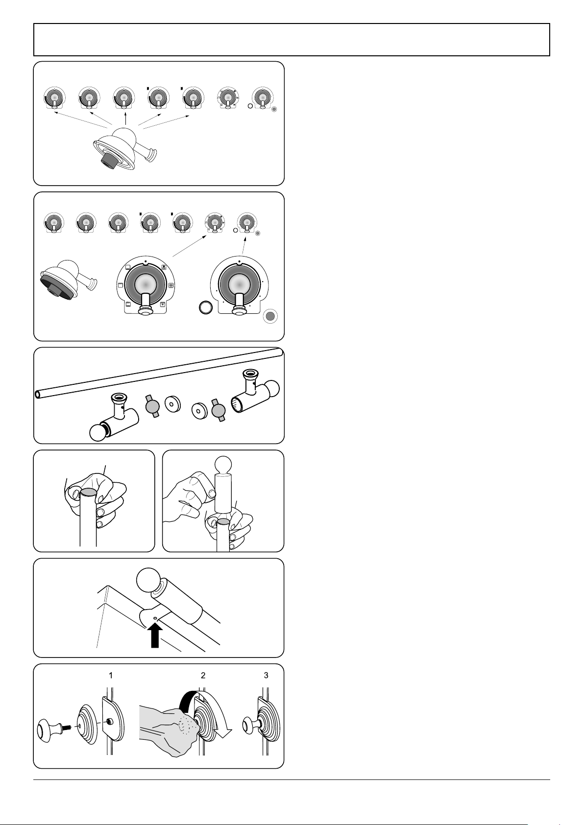
Installing the control knobs
The range is supplied with 5 cooktop control knobs. These are
for the induction controls to the left of the control panel
(Fig. 10.16).
There are also 2 oven control knobs (Fig. 10.17).
Push the multi-function oven selector knob and temperature
knob on to the control spindles at the right-hand side of the
control panel.
Installing the handrail
Components (Fig. 10.18)
• 1x Hand rail tube
• 2x End cap with Allen fixing screw
• 2x Plastic friction cup
Hold a friction cup by the tabs on one end of the tube
(Fig. 10.19).
Line up one of the end caps to the tube and push it on the
tube over the friction cup (Fig. 10.20).
Turn the tube over and push on the other end cap using the
second friction cup, making sure that you DO NOT scratch or
damage the rst end piece and conrm the two end pieces
are lined up correctly.
The Allen screws should be on the underside (Fig. 10.21).
Installing the door handle
Attach the door knob to the door knob base and screw it to
the mounting on the oven door. Hand tighten only – DO NOT
use any tools (Fig. 10.22).
Installing the toe kick
Remove the 3 screws for the toe kick mounts along the
bottom front edge of the range. Fasten the toe kick using
these screws (alternative color screws can be found in the
loose parts pack).
Side panel extension kit (optional extra)
Two side extension panels are supplied with the range. These
can be installed where the side of the range is exposed,
preferably during the installation of the appliance.
Procedure
1. Loosen the 2 screws in the rear edge of the range side
panel.
2. Using the cut-outs, site the side extension onto the
protruding screw heads (Fig. 10.23).
3. Push the side extension up so that the tab in the bottom
of the ue extension ts into the slot at the top
(Fig. 10.24).
4. Hold the side extension in place and tighten the screws
to secure.
Fig. 10.16
Fig. 10.17
Fig. 10.18
Fig. 10.19 Fig. 10.20
Fig. 10.21
Fig. 10.22
Ensure the graphics around the knob match those on the fascia
Loading ...
Loading ...
Loading ...