Loading ...
Loading ...
Loading ...
aXis CONTROLLER HOME STANDBY GENERATOR
INSTALLATION
39
3. Press TEST button.
4. The engine will start and the ATS will transfer.
5. The aXis Controller screen will indicate that the generator is
now suppling power to the home.
WARNING
The manufacturer recommends that a licensed electrician or
an individual with complete knowledge of electricity perform
these tests.
6. With rated load applied, check voltage and frequency across
ATS GENERATOR SUPPLY terminals L1 and L2. Voltage must
be greater than 216 Volts.
7. Frequency should be greater than 58 Hertz.
8. Verify that the gas pressure remains within the acceptable
parameters as listed in the manual, provided that you placed
a Manometer in line prior to starting this test.
9. In test mode, the HSB will run under load for 15 minutes at
which time it will conclude the test and shut off automatically.
With the unit running listen for unusual noises, inspect for
vibrations or other unusual items that might reflect a problem.
10. To stop the test prior to automatic shut off, press the Test
Button in the ATS a second time.
11. The HSB will run through a cool down cycle, shut down and
return to standby mode.
The test is now complete and the system is in standby mode.
Checking Automatic Operation
To check the HSB system for proper automatic operation, proceed
as follows:
1. Turn the ATS utility side breaker OFF.
2. Engine will start and the ATS will transfer.
3. Allow the system to go through a complete cycle.
(Approximately 7 minutes)
4. To conclude Automatic Operation Check, turn the ATS utility
side breaker ON.
5. The HSB will run through a cool down cycle, shut off, and
return to standby mode.
6. Replace covers on ATS and HSB that were removed for HSB
Test and Checking Automatic Operation. This check is now
complete.
Installing Standby Generator to non-aXis
Controller ™ ATS
OTE: N This section is only for those looking to install their aXis
Controller™ HSB to a non-aXis Controller™ ATS that
supports a two-wire HSB start/stop signal. Please refer to
the ATS installation manual for instructions on how to wire
the ATS.
If the aXis Controller™ HSB is being connected to a non-
aXis Controller™ ATS, it will be necessary to use a two-wire
connection shown below to control the on/off operation of this
HSB. Note that this will disable some of the aXis Controller™
features such as load management, WiFi connectivity, and
wireless exercise programming.
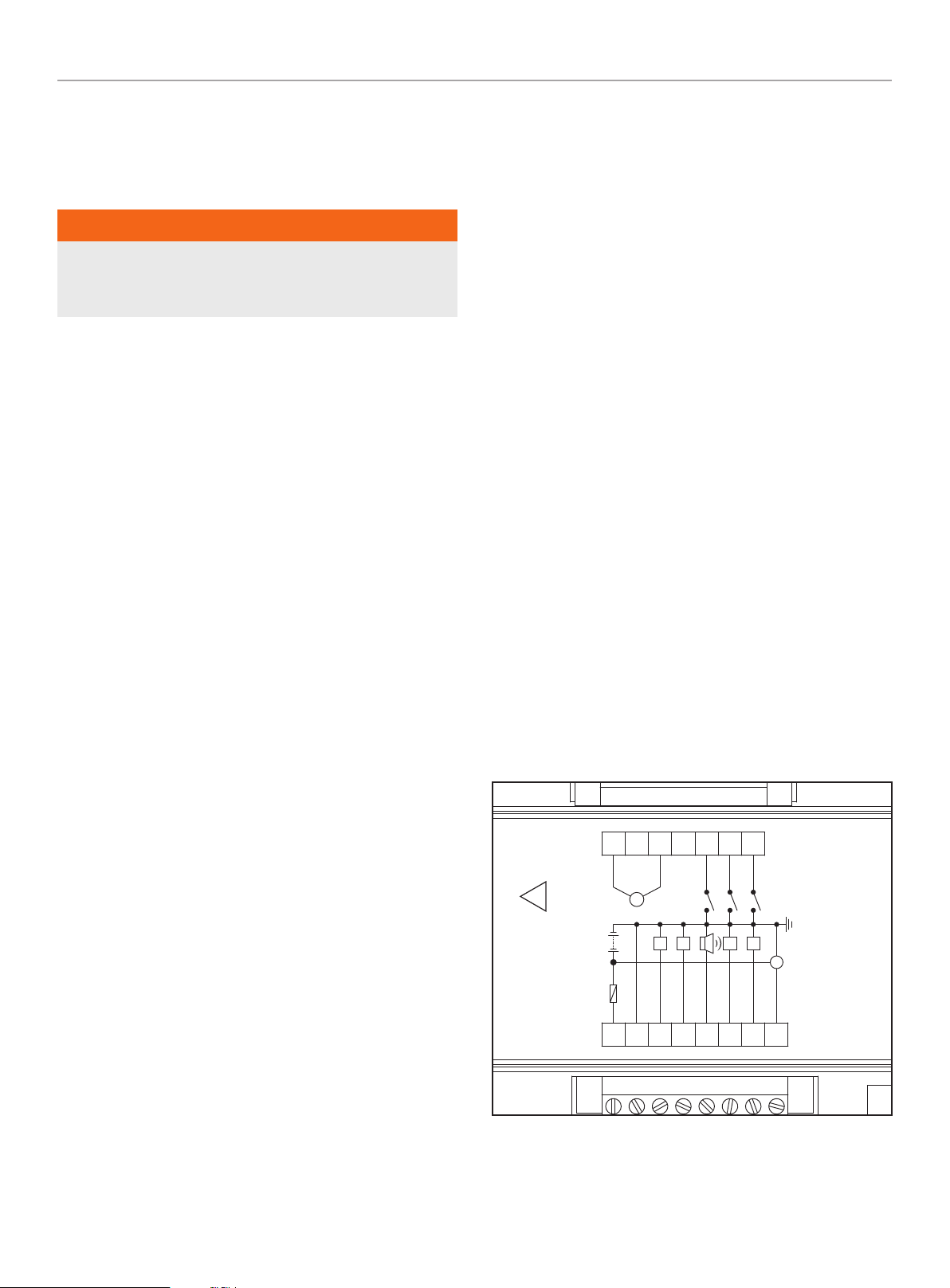
TWO-WIRE CONNECTION
A two-wire connection refers to a signal circuit that runs between
the non-aXis Controller™ ATS and the HSB. When installed in this
configuration, the HSB will turn on and off based on the signal it is
receiving from the ATS.
The aXis Controller™ HSB uses pin 2 and pin 11 on the back of
the aXis Controller™ to control two-wire starting. When pin 11
(normally 5VDC) is connected to pin 2 (ground), the generator will
start and will continue to run until pin 11 is disconnected from pin
2 (ground). When pin 11 is disconnected from pin 2 (ground), the
HSB will start the cool-down cycle and stop.
To wire the HSB to be controlled by the two-wire start signal, tap
into the wires for pin 2 and pin 11 on the HSB and run them to a
relay (not provided) that will close the circuit when the ATS wants
the generator to run. Refer to the ATS instructions for the ATS
logic on how to create the circuit.
CRANKFQ2
I_AUX
I_LOP
I_HWT
FQ1
B-
ALARM
STOP
PREHEAT
FUEL
CHARGER
(D+)
B+
~
Rated Supply:
8~36 VDC (5A Max,)
(Terminal 13 and 15)
MAX WORKING
VOLTAGE
300 VAC
!
1
9151011
12
1314
8765432
ON
91108765432
Loading ...
Loading ...
Loading ...