Loading ...
Loading ...
Loading ...
aXis CONTROLLER HOME STANDBY GENERATOR
INSTALLATION
29
2. Connector #2 (center), has 2 leads. The top lead is BROWN,
when connected it runs to pre-boost/magnetized pin #7 on
the Engine Controller Module. The bottom lead is GREEN and
runs to ground.
3. Connector #3 (far right connector), has 2 leads. A RED lead
(top) that runs to the positive side of the brush assembly, and
a BLACK lead (bottom) that runs to the negative side of the
brush assembly. The brush assembly provides flow through
of excitation current to the rotating rotor. Brushes are made
of long lasting material that seldom wear out or fail. The
contact points of the brush assembly are with two slip rings
attached to the rotor. These slip rings can become tarnished
or exhibit a glaze, which can create a resistance to the flow
of electricity. This can occur when the HSB is not exercised or
ran over long periods of storage.
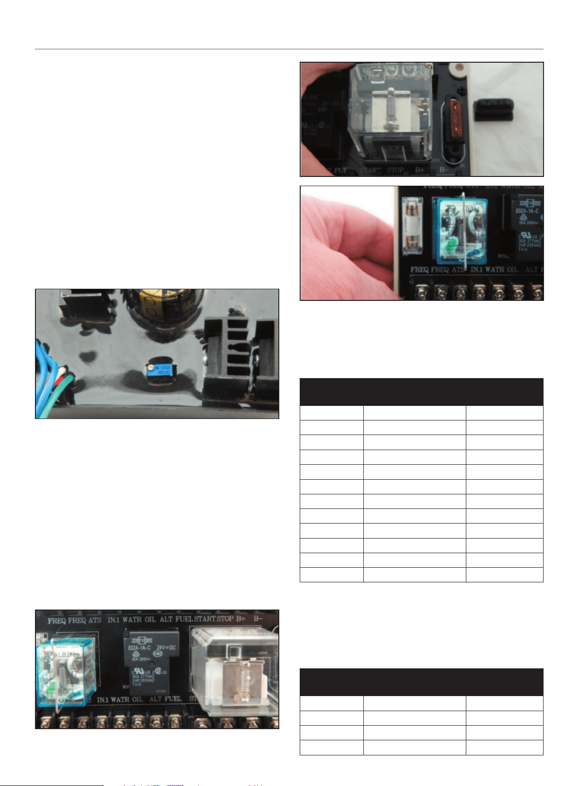
Slotted potentiometer is factory set to the correct voltage and
should not require adjustment.
Engine Relay Module
This module is the interface between the Engine Controller, ATS
Controller, alternator, hour meter and battery charger. It is the
interface for all on board communications in the HSB.
The module has two (2) fuses built into the board. On the left
side of the module there is a 250VAC 5A mini fuse protecting
the system from an over voltage between the alternator and the
relays.
The second fuse, is an automotive style fuse, 40A (Orange), which
protects the system from an excessive transfer voltage output
when the ATS relays transfer between Utility to Genset and Genset
to Utility modes.
TOP ROW
There are 12 wire land points in the top row, the connection points
are all the same size. The following are the wire land points,
function and wire color, this is viewed left to right.
Wire Land
Points
Function Wire Color
Position #1 Frequency R (Red)
Position #2 Frequency B (BLACK)
Position #3 Not connected Empty
Position #4 Not connected Empty
Position #5 High engine temperature BR (brown)
Position #6 Low oil level/pressure Y (yellow)
Position #7 Not connected Empty
Position #8 Fuel supply valve G/B (green/black)
Position #9 Starter B/W (black/white)
Position #10 Stop L/B (blue/black)
Position #11 B+ W (white)
Position #12 B- G (green)
BOTTOM ROW
There are 12 wire land points in the bottom row, 8 are the same
size, the remaining 4 points are larger, viewed left to right. The
following are the wire land points, function and wire color, this is
viewed left to right.
Wire Land
Points
Function Wire Color
Position #1 Frequency R (red)
Position #2 Frequency B (black)
Position #3 Not connected Empty
Position #4 Not connected Empty
Loading ...
Loading ...
Loading ...