Loading ...
Loading ...
Loading ...
Place a combination square against face of fence
and table surface. The fence and table must be at
90° to each other. If not, loosen tilting handle, loosen
hex nut and turn shaft with a screw driver until fence
is square. Secure in position by tightening hex nut.
Use a bevel gauge or protractor to check 45° inward
and outward limit stops. The 45 ° inward stop is the
hex head bolt located beneath the shaft. The 45 °
outward stop is located at the top of the fence. If
adjustment is needed, loosen hex nut, turn hex head
bolt to proper position and secure in place with hex
nut.
Block
Limit Plate._l k
Hex Nut
45 ° Stop
Figure 4 - Limit Stops
INSTALL DUST CHUTE
Refer to Figure 25, page 16.
• Insert pan head screw (Key No. 19) through tabs on
dust chute (Key No. 18). Slide dust chute onto end of
chip exhaust (Key No. 17). Tighten pan head screw.
INSTALLING THE HALF BAG DUST
COLLECTION SET
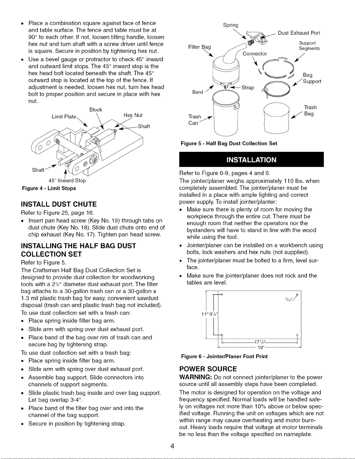
Refer to Figure 5.
The Craftsman Half Bag Dust Collection Set is
designed to provide dust collection for woodworking
tools with a 21/2'' diameter dust exhaust port. The filter
bag attachs to a 30-gallon trash can or a 30-gallon x
1.3 mil plastic trash bag for easy, convenient sawdust
disposal (trash can and plastic trash bag not included).
To use dust collection set with a trash can:
• Place spring inside filter bag arm.
• Slide arm with spring over dust exhaust port.
• Place band of the bag over rim of trash can and
secure bag by tightening strap.
To use dust collection set with a trash bag:
• Place spring inside filter bag arm.
• Slide arm with spring over dust exhaust port.
• Assemble bag support. Slide connectors into
channels of support segments.
• Slide plastic trash bag inside and over bag support.
Let bag overlap 3-4".
• Place band of the filter bag over and into the
channel of the bag support.
• Secure in position by tightening strap.
Filter Bag
Spring
""-.. _-__...-- Dust Exhaust Port
Support
Segments
Connector
Bag
Strap _ _//Support
___ Trash
Bag
Figure 5 - Half Bag Dust Collection Set
4
Refer to Figure 6-9, pages 4 and 6.
The jointer/planer weighs approximately 110 Ibs. when
completely assembled. The jointer/planer must be
installed in a place with ample lighting and correct
power supply. To install jointer/planter:
• Make sure there is plenty of room for moving the
workpiece through the entire cut. There must be
enough room that neither the operators nor the
bystanders will have to stand in line with the wood
while using the tool.
• Jointer/planer can be installed on a workbench using
bolts, lock washers and hex nuts (not supplied).
• The jointer/planer must be bolted to a firm, level sur-
face.
• Make sure the jointer/planer does not rock and the
tables are level.
11" 9W'
[
171/4,,
19"
Figure 6 - Jointer/Planer Foot Print
%,,j/_
POWER SOURCE
WARNING: Do not connect jointer/planer to the power
source until all assembly steps have been completed.
The motor is designed for operation on the voltage and
frequency specified. Normal loads will be handled safe-
ly on voltages not more than 10% above or below spec-
ified voltage. Running the unit on voltages which are not
within range may cause overheating and motor burn-
out. Heavy loads require that voltage at motor terminals
be no less than the voltage specified on nameplate.
Loading ...
Loading ...
Loading ...