Assembly instructions © 2017
© 2017 Char-Broil, LLC Columbus, GA 31902
Printed in China
06/07/17 • G466-016-150801
.
Date Purchased
IMPORTANT: Fill out the product record information below.
See rating label on unit for serial number.
For support with your new barbecue, please call us at:
Amalgamated Hardware Merchants
Ph: 07 3208 1233
Email: [email protected]
Note: Sales docket must be kept as proof of
purchase date.
For use with propane gas only ● For Outdoor Use Only
DO NOT USE INDOORS.
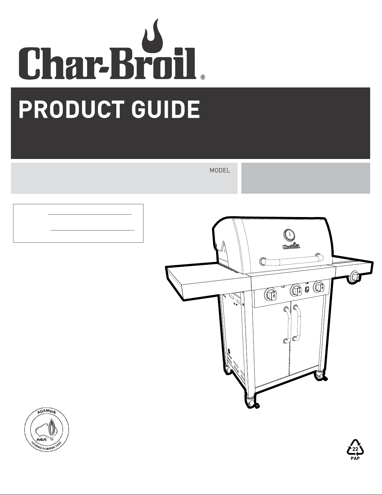
467790317, 467791317
Professional 3 Burner
Gas Grill
AGA 8544 G
2
1.Do not store or use petrol or other
flammable liquids or vapors in the vicinity of
this or any other appliance.
2.A gas cylinder not connected for use shall not
be stored in the vicinity of this or any other
appliance.
WARNING
CAUTION
For residential use only. Do not use for commercial
cooking.
DANGER
DANGER: Indicates an imminently hazardous situation
which, if not avoided, will result in death or serious injury.
WARNING
WARNING: Indicates an potentially hazardous situation
which, if not avoided, could result in death or serious injury.
CAUTION
CAUTION: Indicates a potentially hazardous situation or
unsafe practice which, if not avoided, may result in minor
or moderate injury.
Safety Symbols
The symbols and boxes shown below explain what each heading
means. Read and follow all of the messages found throughout
the manual.
DANGER
If you smell gas:
1.Shut off gas to the appliance, if possible.
2.Extinguish any open flame.
3.Open lid.
4.If odor continues, keep away from the
appliance and immediately call your gas
supplier or your fire department.
THIS BARBECUE IS FOR OUTDOOR USE ONLY.
CAUTION:
Read and follow all safety statements, assembly
instructions, and use and care directions before attempting
to assemble and cook.
INSTALLER/ASSEMBLER:
Leave this manual with consumer.
CONSUMER:
Keep this manual for future reference.
WARNING:
Failure to follow all manufacturer’s instructions could result
in serious personal injury and/or property damage.
CAUTION:
Some parts may contain sharp edges – especially as noted
in the manual! Wear protective gloves if necessary.
FOR YOUR SAFETY
2
TABLE OF CONTENTS
WARNING
DO NOT MODIFY THIS APPLIANCE.
IF THIS APPLIANCE REQUIRES SERVICING,
THE SERVICE MUST BE CARRIED OUT BY
AUTHORIZED PERSONNEL ONLY.
NEVER OPERATE THIS BARBECUE FOR
MORE THAN 15 MINUTES WITH THE LID
CLOSED.
For Your Safety..........................................................................2-3
Use and Care.........................................................................4-10
Limited Warranty.........................................................................11
Parts List.....................................................................................12
Parts Diagram.............................................................................13
Assembly................................................................................14-33
Troubleshooting......................................................................36-37

3
WARNING
The barbecue has been evaluated for safety only with one
griddle plate. Use of more may create an unsafe condition.
Gas Installation Codes
The appliance is certified
To AS 5263.0 and 5263.1.7 by AGA
Barbecue must be used in accordance with the
installation requirements of your local gas supply
authority, and the appropriate installation standard
AS 5601.
Gas Connection Requirements.
The regulator supplied with the barbecue must be used.
The regulator is supplied with a POL cylinder connection
for connection to a 9 kg gas cylinder.
The regulator supplied has a outlet pressure of 2.75 kPa
This pressure is preset and cannot be adjusted.
USE OF BARBECUE UNDER OVERHEAD
While acceptable locations to use the barbecue are shown
on page 6. Char-Broil recommends not to use the barbecue
under any overhead. The smoke from cooking, especialy
with IR cooking, contains grease particles which will deposit
on the overhead.
Specification
3 main burners at 8.43 MJ/h each
1 side burner at 13.7 MJ/h
Total 39.0 MJ/h
Gas consumption @ 2.75 kPA
Injector size
Main burners - 0.82 mm
Injector size
Side burner - 1.07 mm
Check that "o" ring seal between the appliance
and the gas container are in place and in good
condition before connecting the gas container
Do not use this appliance if it has damaged or
worn "o" ring seal.
Each time prior to connecting regulator to
cylinder verify “o” - ring is in position as shown
below.
If damaged or missing replace prior to use.
WARNING
Leak check the regulator cylinder connection at
each use as shown on page 5.
Recommended Maintenance
Each Use
Clean and oil cooking grate assemblies
Clean/Inspect firebox
Clean grease tray
Check gas supply hose for cracks/leaks
Check gas regulator for leaks
Check that all gas fittings are tight
Every 6 months
Clean/Inspect burners and venturis
Check burners for corrosion
Others
Leak checks as specified in guide
Seal
O-Ring
4
USE AND CARE
Gas Cylinder Removal, Transport and Storage
•Turn OFF all control knobs and gas cylinder valve. Turn coupling
nut clockwise to disconnect. Lift gas cylinder up and out of trolley.
Do not store a gas cylinder in enclosed spaces
such as a carport, garage, porch, covered
patio or other building. Never leave a gas cylinder
inside a vehicle which may become overheated
by the sun.
• Do not store a gas cylinder in an area where children play.
LPG (Liquefied Petroleum Gas including Propane)
• LPG is nontoxic, odorless and colorless when produced. For
Your Safety, LPG has been given an odor (similar to rotten
cabbage) so that it can be smelled.
• LPG is highly flammable and may ignite unexpectedly when
mixed with air.
Gas Cylinder Filling or Exchange
• Use only licensed and experienced gas dealers or exchange
• A frosty regulator indicates gas overfill. Immediately close gas
cylinder valve and call local gas dealer for assistance.
• Do not release liquid propane gas into the atmosphere.
This is a hazardous practice.
• To remove gas from cylinder, contact a gas dealer or call a
local fire department for assistance.
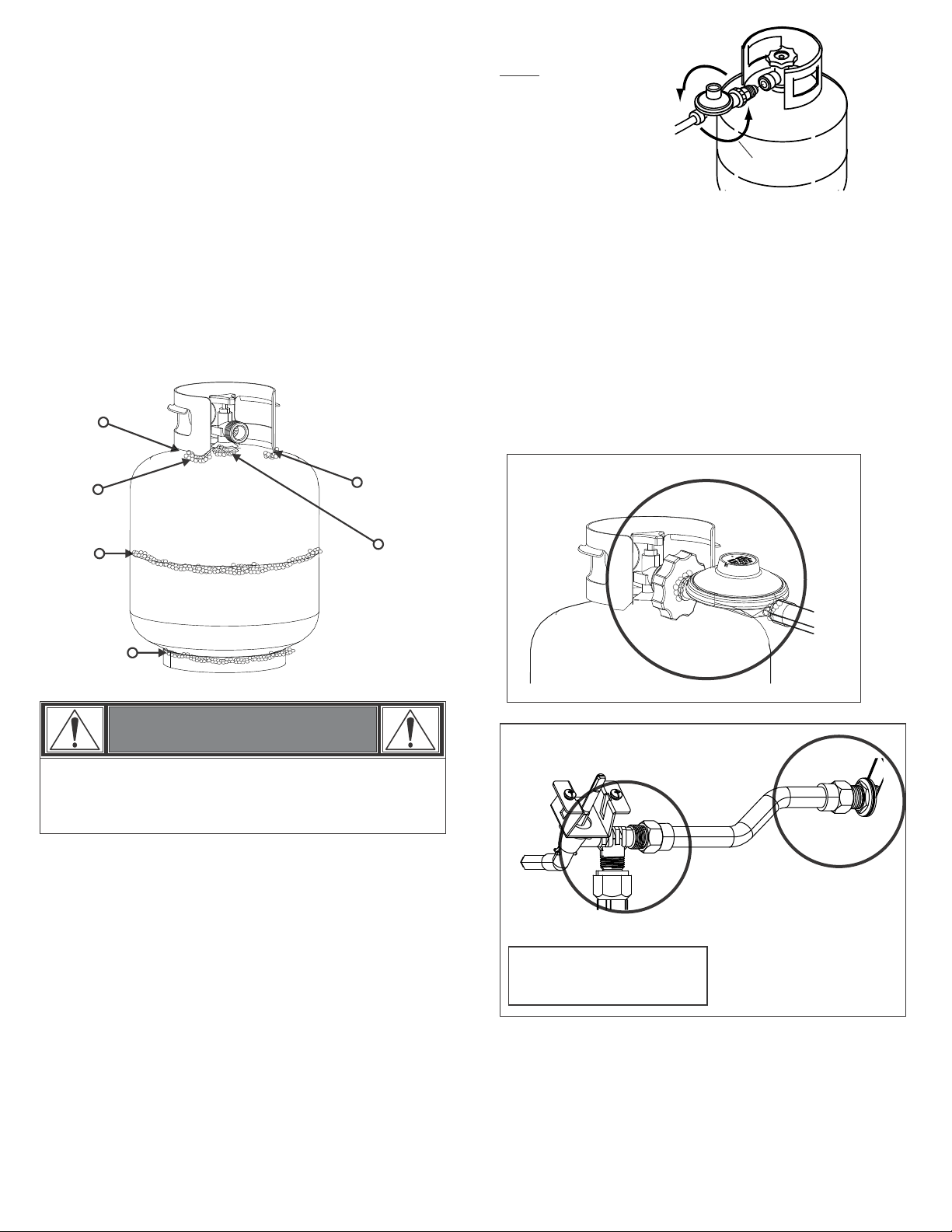
Cylinder Valve
Gas Cylinder
• The gas cylinder used with your barbecue must meet the
following requirements:
• Use gas cylinders only with these required measurements:
30.5 cm diameter x 45.7 cm tall with 9 kg. capacity maximum.
Gas cylinder must be arranged for vapor withdrawal and include
collar to protect gas cylinder valve. Always keep gas cylinders in
upright position during use, transit or storage.
Gas cylinder in upright position for vapor withdrawal
Ensure gas cylinder conforms to Australian Standard
AS2469 and is less than 10 years old, or re-certified
if older than 10 years.
•
•
Do not subject gas cylinder to excessive heat.
•
at a reputable cylinder exchange outlet.
•Outdoor gas appliance is not intended to be installed
in or on a boat.
•Outdoor gas appliance is not intended to be installed
in or on a caravan.
•Never attempt to attach this barbecue to the self-
contained gas system of a caravan.
•Do not use barbecue until leak-tested.
•If a leak is detected at any time, STOP.
•
If you cannot stop a gas leak, immediately close
gas cylinder valve and call gas supplier or your fire
department!
WARNING
• Always disconnect regulator from cylinder, never disconnect
hose from barbecue. Gas hoses are factory fitted and
leak tested.
•
This is the minimum cylinder that can be used.
facility provided.
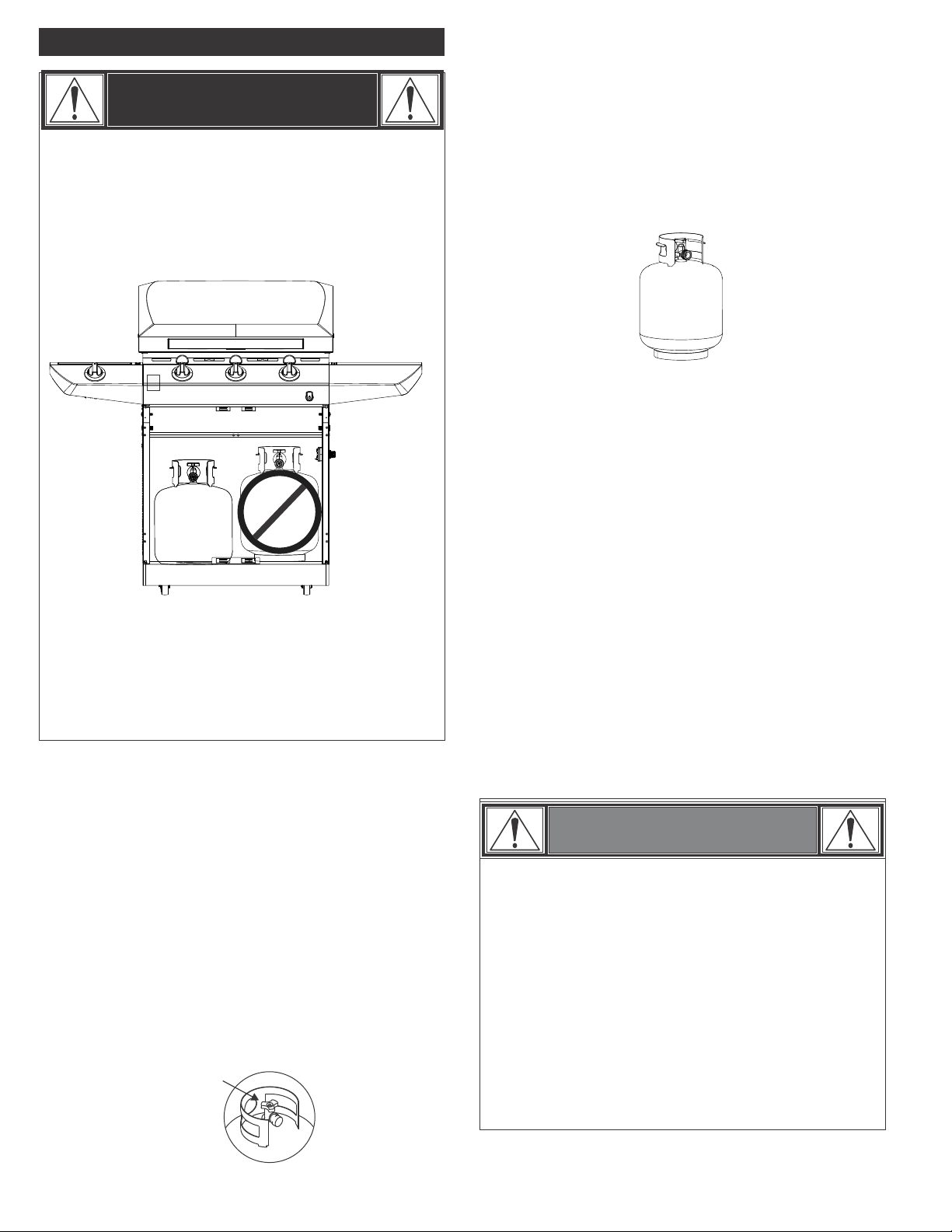
If this warning is not followed, a fire causing
injury or damage may occur.
•
•
Do not store spare gas cylinder/s in this compartment
or near this appliance; use only the cylinder storage
•If you see, smell or hear gas escaping,
immediately get away from the gas
cylinder/appliance and call your fire department.
WARNING
5
WARNING
If “growing” bubbles appear do not use or move the gas
cylinder. Contact a gas supplier or your fire
department!
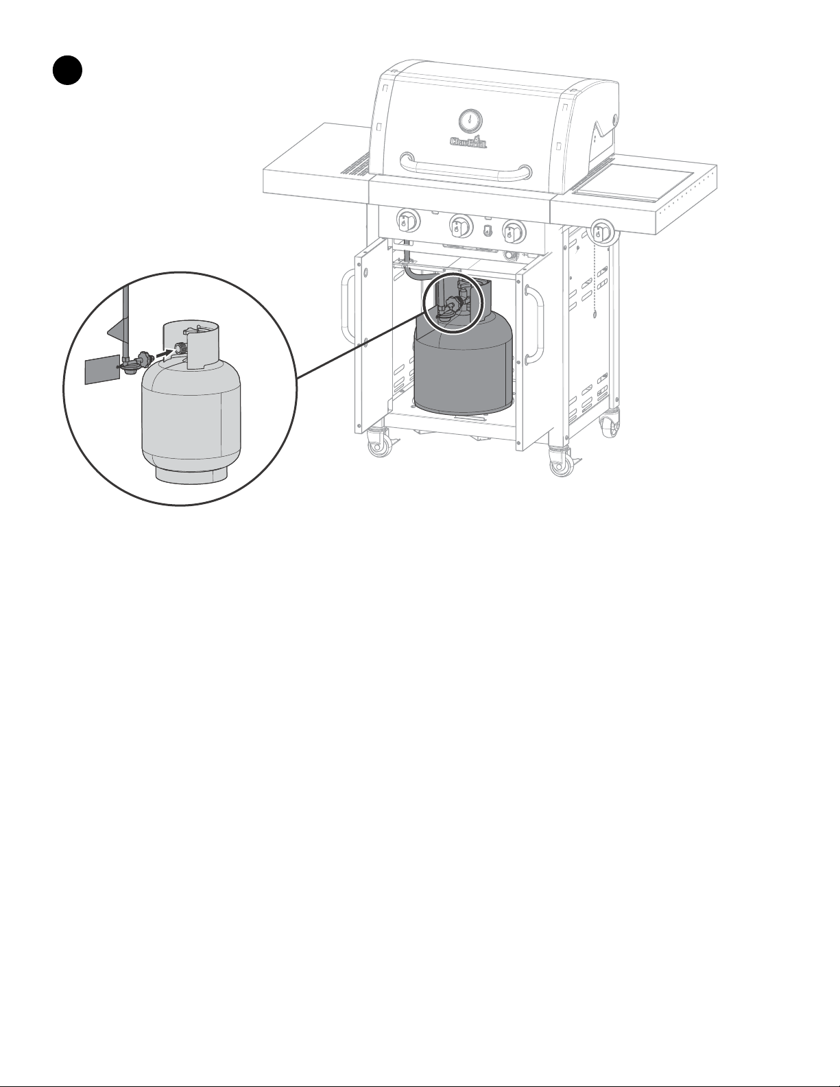
Connecting Regulator to the Gas Cylinder
1.Gas cylinder must be properly secured onto barbecue. (Refer to
assembly section.)
2.Turn all control knobs to the OFF position.
3.Turn gas cylinder OFF by turning hand wheel clockwise to a
full stop.
Gas Cylinder Leak Test
For your safety
• Leak test must be repeated each time gas cylinder is exchanged
or refilled.
• Do not smoke during leak test.
• Do not use an open flame to check for gas leaks.
• Barbecue must be leak tested outdoors in a well-ventilated area,
away from ignition sources such as gas fired or electrical
appliances. During leak test, keep barbecue away from open flames
or sparks.
• Use a clean paintbrush and a 50/50 mild soap and water
solution.
Do not use household cleaning agents. Damage to gas
train components can result.
Brush soapy solution onto areas indicated by arrows
in figure below.
5. Hold regulator and insert nipple into
cylinder valve. Tighten the
coupling nut, holding regulator in a
straight line with gas cylinder
valve so as not to cross-thread the connection.
NOTE:
The connection to
the gas cylinder is an
‘ANTI-CLOCKWISE connection.’
Ensure the connection
is tightened firmly. Normally
only 1-1
1
/
2
threads of the hose
assembly connection should
remain visible.
Direction for
tightening
Leak Testing Valves, Hose and Regulator
1.Turn all barbecue control knobs to OFF.
2.Be sure regulator is tightly connected to gas cylinder.
3.Completely open gas cylinder valve by turning hand wheel
counterclockwise. If you hear a rushing sound, turn gas off
immediately. There is a major leak at the connection. Correct
before proceeding.
4.Brush soapy solution onto areas circled below, or other similar
5.If “growing” bubbles appear, there is a leak. Close gas
cylinder valve immediately and retighten connections. If leaks
cannot be stopped do not try to repair. Call for replacement
parts.
6.Always close gas cylinder valve after performing leak test by
turning hand wheel clockwise.
fittings on your barbecue.
4. Prior to connecting check o ring on regulator nipple
for damage. Replace if damaged.
•
NOTE: Sideburner shelf
fascia and other parts not
shown for clarity.
6
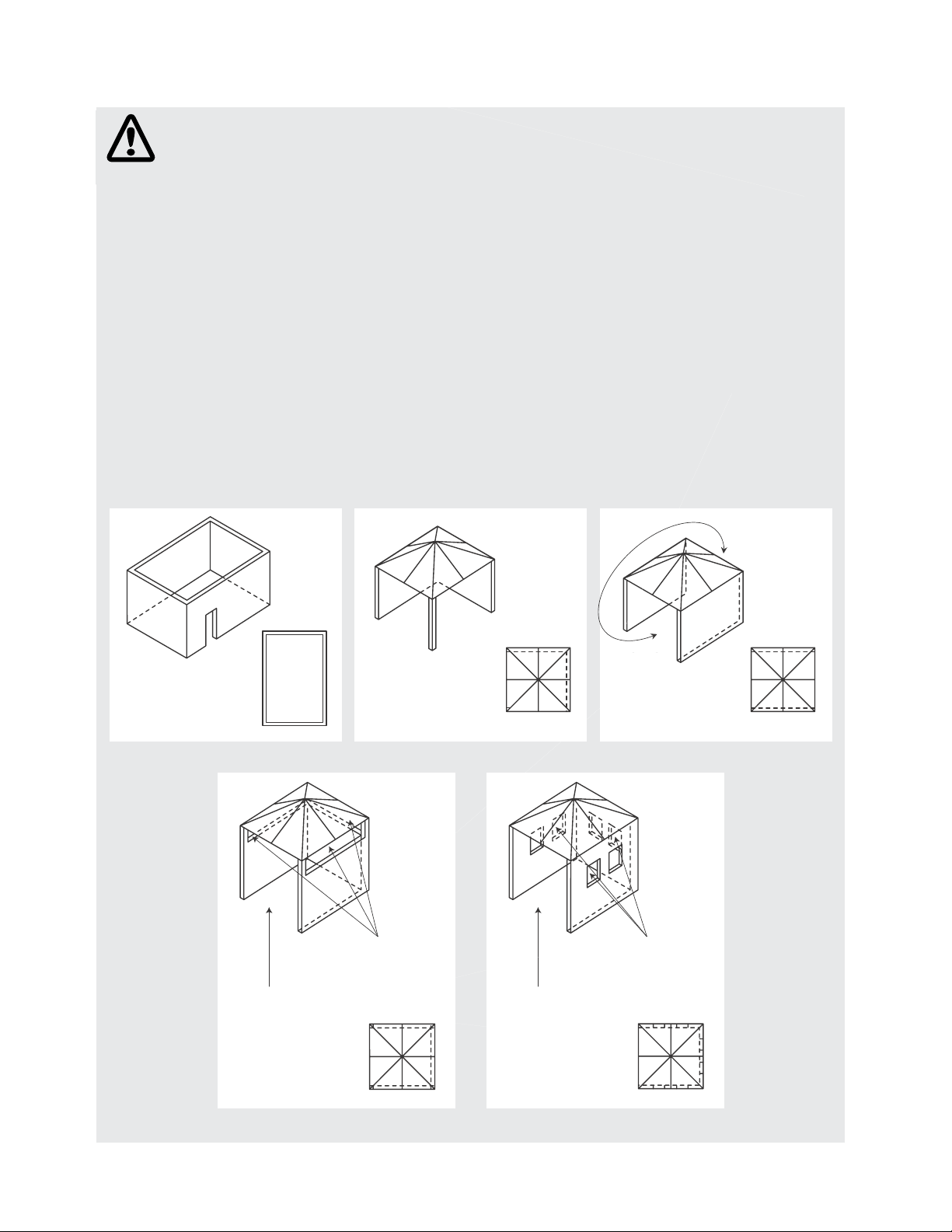
The following diagrams are examples of outdoor areas.
These same principles apply to canopy or shaded cloth areas.
THIS APPLIANCE SHALL ONLY BE USED IN AN ABOVE GROUND OPEN AIR SITUATION WITH NATURAL
VENTILATION, WITHOUT STAGNANT AREAS, WHERE GAS LEAKAGE AND PRODUCTS OF COMBUSTION
ARE RAPIDLY DISPERSED BY WIND AND NATURAL CONVECTION.
ANY ENCLOSURE IN WHICH THE APPLIANCE IS USED SHALL COMPLY WITH ONE OF THE FOLLOWING:
•AN ENCLOSURE WITH WALLS
ON ALL SIDES, BUT AT LEAST
ONE PERMANENT OPENING AT
GROUND LEVEL AND NO
OVERHEAD COVER
•WITHIN A PARTIAL
ENCLOSURE THAT INCLUDES
AN OVERHEAD COVER AND NO
MORE THAN TWO WALLS
•WITHIN A PARTIAL
ENCLOSURE THAT INCLUDES
AN OVERHEAD COVER AND
MORE THAN TWO WALLS, THE
FOLLOWING SHALL APPLY:
(i) AT LEAST 25% OF THE TOTAL
WALL AREA IS COMPLETELY
OPEN: AND
(ii) AT LEAST 30% OF THE
REMAINING WALL AREA IS
OPEN AND UNRESTRICTED
•IN THE CASE OF BALCONIES,
AT LEAST 20% OF THE TOTAL
OF THE SIDE, BACK AND FRONT
WALL AREAS SHALL BE AND
REMAIN OPEN AND
UNRESTRICTED
•DO NOT USE YOUR BARBECUE
IN GARAGES, PORCHES,
BREEZEWAYS, SHEDS OR
OTHER ENCLOSED AREAS.
YOUR BARBECUE IS TO BE
USED OUTDOORS ONLY.
Refer below.
•THE BARBECUE IS NOT
INTENDED TO BE INSTALLED IN
OR USED ON RECREATIONAL
VEHICLES AND/OR BOATS AND
SHOULD NOT BE PLACED
ADJACENT TO OR UNDER ANY
SURFACE THAT WILL BURN.
•DO NOT OBSTRUCT THE FLOW
OF COMBUSTION AND
VENTILATION AIR AROUND
THE BARBECUE HOUSING
WHILST IN USE.
Both ends
open
30% or more in total of
the remaining wall area
is open and unrestricted
30% or more in total of
the remaining wall area
is open and unrestricted
Open side at
least 25% of total
wall area
Open side at
least 25% of total
wall area
7
WARNING
For Safe Use of Your Grill and to Avoid Serious Injury:
• Do not let children operate or play near barbecue.
• Keep barbecue area clear and free from materials that burn.
• Do not block holes in sides or back of barbecue.
• Check burner flames regularly.
• Do not use lump charcoal or ceramic briquettes in
• Use barbecue only in well-ventilated space. NEVER use in
enclosed space such as carport, garage, porch, covered
patio, or under an overhead structure of any kind.
• Do not cover grates with aluminum foil or any other
material. This will block burner ventilation and create a
potentially dangerous condition resulting in property
damage and/or personal injury.
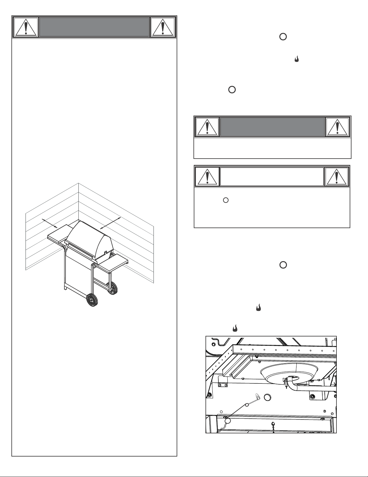
• Use barbecue at least 3 ft. from any wall or surface. Maintain
10 ft. clearance to objects that can catch fire or sources of
ignition such as pilot lights on water heaters, live electrical
appliances, etc.
• Apartment Dwellers:
Check with management to learn the requirements and fire
codes for using an LP gas barbecue in your apartment complex.
If allowed, use outside on the ground floor with a three (3)
foot clearance from walls or rails. Do not use on or under
balconies.
• NEVER attempt to light or re-light burner with lid
closed. A buildup of non-ignited gas inside a closed
barbecue is hazardous.
• Never operate barbecue with LP cylinder out of correct
position specified in assembly instructions.
• Always close LP cylinder valve and remove coupling nut
Before moving LP cylinder from specified operation
position.
3 ft.
3 ft.
a gas barbecue.
ŸDO NOT SPRAY AEROSOLS IN THE VICINITY OF THIS
APPLIANCE WHILE IT IS IN OPERATION.
ŸDO NOT USE OR STORE FLAMMABLE MATERIALS IN OR
NEAR THIS APPLIANCE.
ŸDO NOT PLACE ARTICLES ON OR AGAINST THIS
APPLIANCE. DO NOT MODIFY THIS APPLIANCE.
• Do not lean over grill while lighting.
1. Turn gas burner control valves to (off).
2. Open lid during lighting or re-lighting.
3. Turn ON gas at LP cylinder.
Ignitor Lighting
Match-Lighting
If ignition does NOT occur in 5 seconds, turn the burner
controls off, wait 5 minutes and repeat the lighting
procedure. If the burner does not ignite with the valve
open, gas will continue to flow out of the burner and
could accidently ignite with risk of injury.
Turn controls and gas source or tank OFF when not
in use.
4. Place match into match holder (hanging from side panel of
grill). Light match; then light burner by placing match through
the match light hole on side of grill. Immediately push in and
turn burner knob to the HIGH position. Be sure burner lights
and stays lit.
CAUTION
WARNING
• Do not lean over grill while lighting.
1. Turn gas burner control valves to (off).
2. Open lid during lighting or re-lighting.
3. Turn ON gas at LP cylinder.
4. To ignite, push and turn burner knob to HIGH. Immediately,
push and hold ELECTRONIC IGNITOR button until the burner
lights.
5. If ignition does NOT occur in 5 seconds, turn the burner
controls off , wait 5 minutes and repeat the lighting
procedure.
6. Repeat steps 4 and 5 to light other main burners.
5. Light adjacent burners in sequence by pushing knobs in and
turning to the HIGH position.
8
• Before each use, check to see if hoses are cut or worn or
Kinked. Replace damaged hoses before using barbecue. Use only
valve/hose/regulator specified by manufacturer.
Hose Check
• Important: Make sure gas is off at LP cylinder before
checking valves. Knobs lock in off position. To check valves,
first push in knobs and release, knobs should spring back. If
knobs do not spring back, replace valve assembly before using
Barbecue. Turn knobs to LOW position then turn back to off position.
Valves should turn smoothly.
Valve Check
• Turn gas off at LP cylinder. Press and hold electronic ignitor
button. "Click" should be heard and spark seen each time in
each collector box or between burner and electrode. See
"Troubleshooting" if no click or spark.
Ignitor Check
• Turn all knobs to the off position. Turn LP cylinder off by
turning hand-wheel clockwise to a full stop.
Turning Grill Off
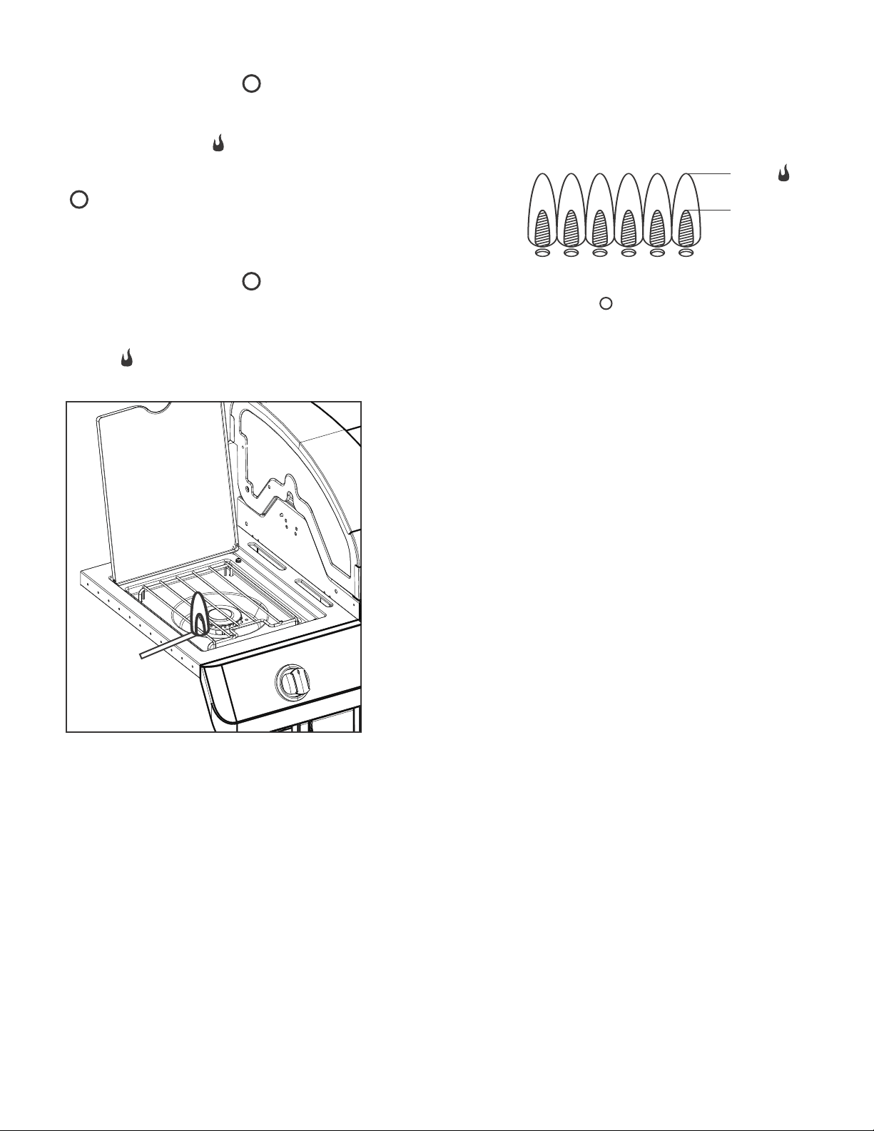
• Remove cooking grates and heat tents. Light burners, rotate
knobs from HIGH to LOW. You should see a smaller flame in
LOW position than seen on HIGH. Perform burner flame check
on side burner, also. Always check flame prior to each use. If
only low flame is seen refer to "Sudden drop or low flame" in
the Troubleshooting Section.
HIGH
LOW
Burner Flame Check
Storing Your Grill
• Clean cooking grates.
• Store in dry location.
• When LP cylinder is connected to barbecue, store outdoors in a
well-ventilated space and out of reach of children.
•
Cover barbecue if stored outdoors. Choose from a variety of barbecue
covers offered by Char-Broil at charbroil.com.
• Store barbecue indoors ONLY if LP cylinder is turned off and
Disconnected, removed from barbecue and stored outdoors.
• When removing barbecue from storage, follow “Cleaning the
Burner Assembly” instructions before starting barbecue.
Sideburner Ignitor Lighting
• Do not lean over grill while lighting.
4. Turn sideburner knob to the HIGH position, push and hold
ELECTRONIC IGNITOR button.
5. If sideburner does NOT light within 5 seconds, turn knob
to off, wait 5 minutes, then repeat lighting procedure.
Sideburner Match Lighting
4. Place lit match near burner. Immediately turn sideburner
knob to the HIGH position. Be sure burner lights and stays
lit.
2. Open lid during lighting or re-lighting.
• Do not lean over grill while lighting.
3. Turn ON gas at LP cylinder.
1. Turn gas burner control valves to (off).
2. Open lid during lighting or re-lighting.
3. Turn ON gas at LP cylinder.
1. Turn gas burner control valves to (off).

9
Storing Your barbecue
•Clean cooking grates.
•Store in dry location.
•When gas cylinder is connected to barbecue, store outdoors in a well-
ventilated space and out of reach of children.
•Cover barbecue if stored outdoors. Choose from a variety of barbecue
covers offered by manufacturer.
•Store barbecue indoors ONLY if gas cylinder is turned off and
Disconnected, removed from barbecue and stored outdoors.
•When removing barbecue from storage, follow “Cleaning the Burner
Assembly” instructions before starting barbecue.
General barbecue Cleaning
•Do not mistake brown or black accumulation of grease and
smoke for paint. Interiors of gas barbecues are not painted at the
factory (and should never be painted). Apply a strong solution
of detergent and water or use a barbecue cleaner with scrub brush
on insides of barbecue lid and bottom. Rinse and allow to completely
air dry. Do not apply a caustic barbecue/oven cleaner to painted
surfaces.
• Plastic parts: Wash with warm soapy water and wipe dry.
Do not use citrisol, abrasive cleaners, degreasers or a
concentrated barbecue cleaner on plastic parts. Damage to and
failure of parts can result.
•Porcelain surfaces: Because of glass-like composition, most
residue can be wiped away with baking soda/water solution or
specially formulated cleaner. Use nonabrasive scouring powder
for stubborn stains.
•Painted surfaces: Wash with mild detergent or nonabrasive
cleaner and warm soapy water. Wipe dry with a soft
nonabrasive cloth.
•Stainless steel surfaces: To maintain your barbecue’s high quality
appearance, wash with mild detergent and warm soapy water
and wipe dry with a soft cloth after each use. Baked-on grease
deposits may require the use of an abrasive plastic cleaning
pad. Use only in direction of brushed finish to avoid damage.
Do not use abrasive pad on areas with graphics.
• Cooking surfaces: If a bristle brush is used to clean any of
the barbecue cooking surfaces, ensure no loose bristles remain on
cooking surfaces prior to barbecueing. It is not recommended to
clean cooking surfaces while barbecue is hot.
•Turn gas off at gas cylinder. Press and hold electronic ignitor
button. "Click" should be heard and spark seen each time
between each collector box or burner and electrode. See
"Troubleshooting" if no click or spark.
Valve Check
•Important: Make sure gas is off at gas cylinder before
checking valves. Knobs lock in position. To check
valves, first push in knobs and release, knobs should spring
back. If knobs do not spring back, replace valve assembly
position. Valves should turn smoothly.
Hose Check
•Before each use, check to see if hoses are cut or worn.
Replace damaged hoses before using barbecue. Use only
valve/hose/regulator specified by manufacturer.
OFF
OFF
before using barbecue. Turn knobs to LOW position then turn back to
Ignitor Check
MAINTENANCE
It is your responsibility to properly maintain your barbecue.
The frequency of the maintenance will depend on the level
you use the barbecue. Cooking grates and hot plates should
be cleaned after or just prior to each use. At least once a year
you need to clean the cooking chamber and inspect the burners
for corrosion. More frequent cleaning will be needed with
heavy use.
It is recommended that an annual inspection be made by a
qualified technician.
Following are recommend items to check at each use and
general cleaning instructions.
CAUTION
SPIDER ALERT!
SPIDER AND WEBS
INSIDE BURNER
If your barbecue is getting hard to light or
the flame is weak, check and clean the
venturis and burners.
Special Operating Instructions
Never operate this barbecue for more than 8 minutes on
high with hood closed.
10
3.Remove carryover tubes and burners.
4.
5.Carefully lift each burner up and away from valve openings.
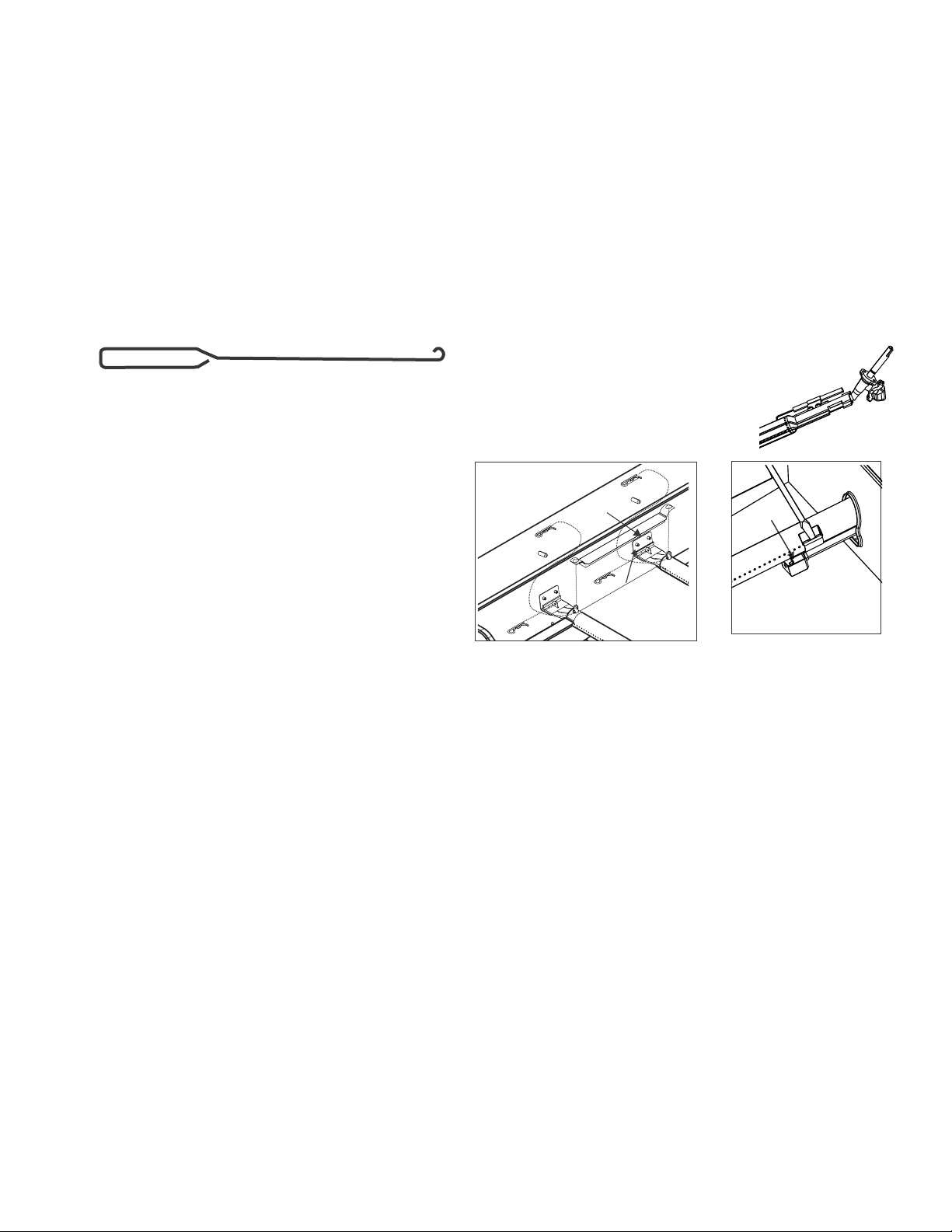
We suggest three ways to clean the burner tubes. Use the one
easiest for you.
(A)Bend a stiff wire (a light weight coat hanger works well)
into a small hook. Run the hook through each burner
tube several times.
(B)Use a narrow bottle brush with a flexible handle (do not
use a brass wire brush), run the brush through each
burner tube several times.
(C)Wear eye protection: Use an air hose to force air into
the burner tube and out the burner ports. Check each
port to make sure air comes out each hole.
6.Wire brush entire outer surface of burner to remove food
residue and dirt.
7.Clean any blocked ports with a stiff wire such as an open
paper clip.
8.Check burner for damage, due to normal wear and corrosion
some holes may become enlarged. If any large cracks or
holes are found replace burner.
VERY IMPORTANT: Burner tubes must reengage valve
openings. See illustrations at right.
9.Attach electrode to burner.
10.Carefully replace burners.
11.Attach burners to brackets on firebox.
12.Reposition carryover tubes and attach
to burners. Replace flame tamers and
cooking grates.
Correct
burner-to-valve
engagement
Detach electrode from burner.
Cleaning the Burner Assembly
Follow these instructions to clean and/or replace parts of burner
assembly or if you have trouble igniting barbecue.
1. Turn gas off at control knobs and gas cylinder.
2.
Remove cooking grates and flame tamers.
Firebox
Carryover tube
Firebox burner
bracket
Pry off
electrode with
a flat blade
screwdriver
Electrode
11
MANUFACTURER’S WARRANTY STATEMENT
The benefits under this manufacturer's warranty are in addition to other rights and remedies
under law in relation to goods. Our goods come with guarantees that cannot be excluded
under the Australian Consumer Law. You are entitled to a replacement or refund for a
major failure and for compensation for any other reasonably foreseeable loss or damage.
You are also entitled to have the goods repaired or replaced if the goods fail to be of
acceptable quality and the failure does not amount to a major failure.
The Manufacturer warrants that this product shall be free from defects in workmanship and
materials at the time of purchase. The manufacturer reserves the right to require that any
product, or portion of a product, that is claimed as defective to be returned for inspection.
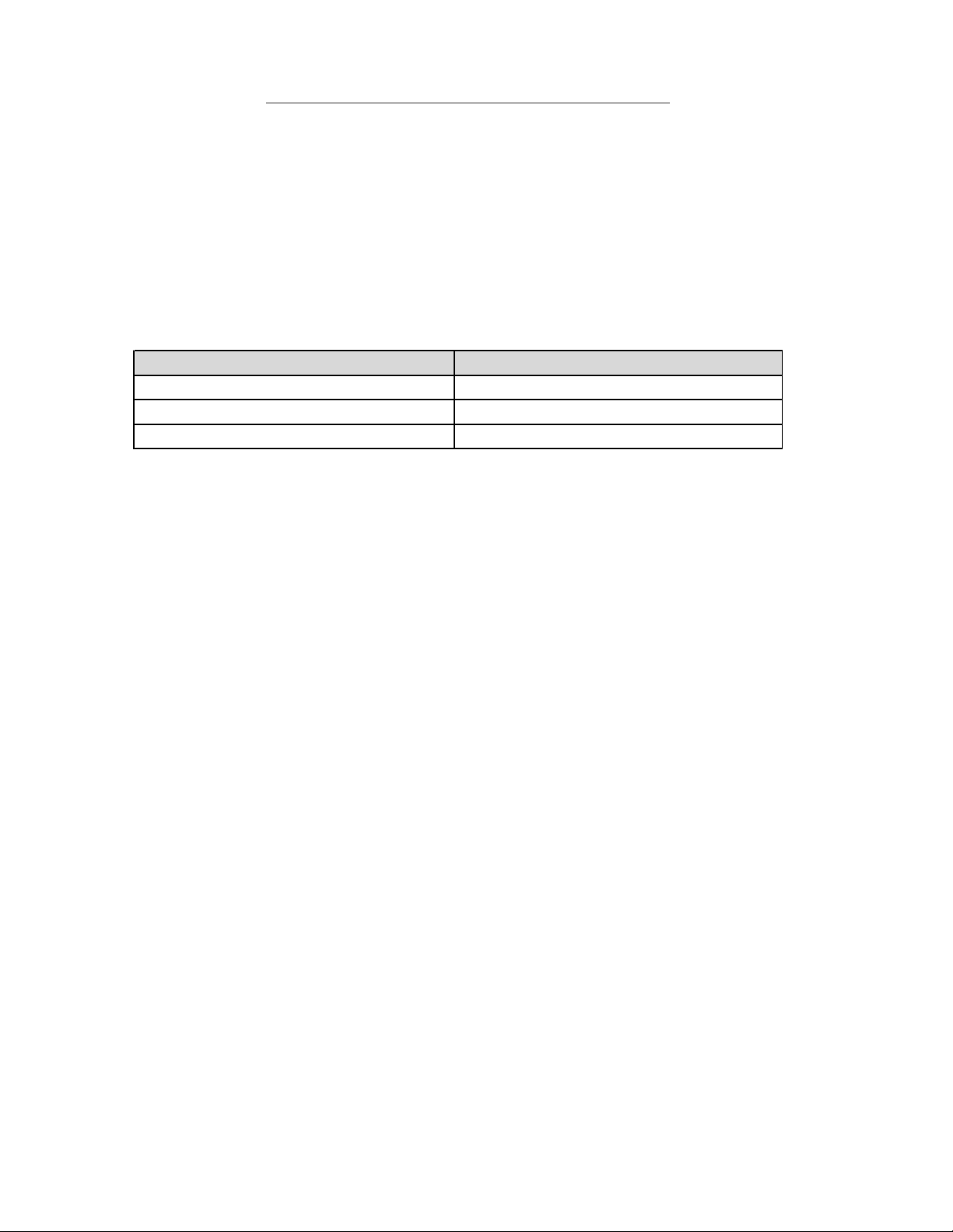
The Manufacturer’s Warranty applies to the parts of your product as per the below table:
To claim under this Manufacturer’s Warranty, you will be required to produce proof of
purchase of your product that clearly states the date of purchase.
The Manufacturer’s Warranty does not include:
1. Transport costs for replacement parts, or for the purpose of returning parts for
inspection.
2. The cost of in-home service calls or works undertaken on your behalf without
the Manufacturer’s authorisation.
3. Loss of food, fuel or other consumables as a result of a fault of the product.
4. Any other form of loss or damage as a result of a fault of the product.
This Manufacturer’s Warranty shall not cover faults or defects that are in the
Manufacturer’s assessment caused by:
1. Improper or incorrect installation or assembly of the product.
2. Alteration or retrofitting of the product in form or function.
3. Usage in a commercial context or uses other than domestic use.
4. Neglect, mistreatment or other acts inconsistent with a reasonable standard
of care for the product.
5. Fair wear and tear, including naturally occurring processes such as
oxidisation causing rust.
The maximum liability assumed under this Manufacturer’s Warranty is limited to the
provision of replacement product or replacement parts for your product.
How to claim under the Manufacturer’s Warranty:
There are two methods of obtaining service under this warranty:
1. Contact your place of purchase.
2. Contact the Australian Distributor:
Amalgamated Hardware Merchants
By mail: Unit 4 – Compton Plaza 126-130 Compton Road WOODRIDGE,
QLD 4114 By phone: (07) 3208 1233
By email: [email protected]
PRODUCT PART DESCRIPTIONPERIOD OF COVERAGE
Stainless Burner2 years fron date of purchase
Firebox and Lid2 years fron date of purchase
All other Parts1 years fron date of purchase
12
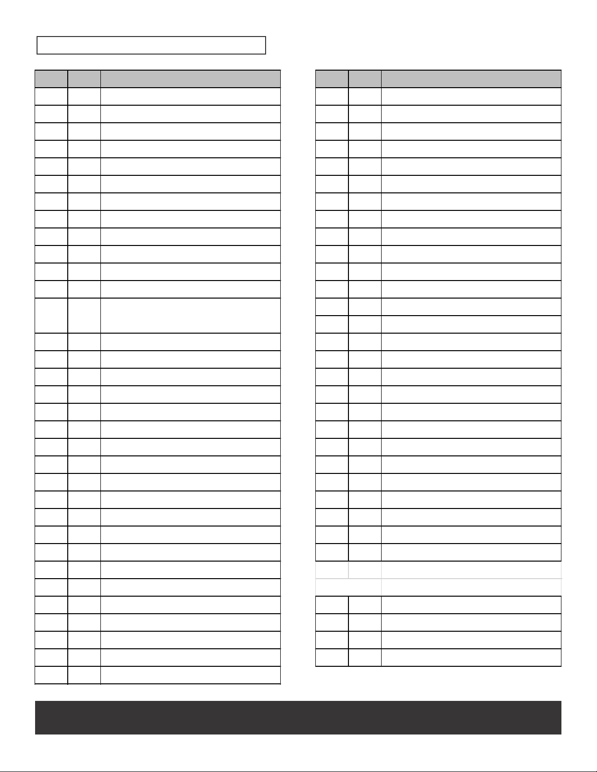
PARTS LIST
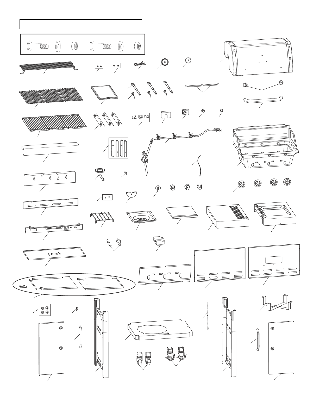
NOTE: Some grill parts shown in the assembly steps may differ slightly in appearance from
those on your particular grill model. However, the method of assembly remains the same.
KeyQtyDescription
11TOP LID
21TEMPERATURE GAUGE
31BEZEL, F/ TEMP GAUGE
41LOGO PLATE
51HANDLE F/ TOP LID
62BEZEL, F/ HANDLE
72RUBBER BUMPER, W/ HOLE, F/ TOP LID
82RUBBER BUMPER, ROUND
91TOP LID HARDWARE
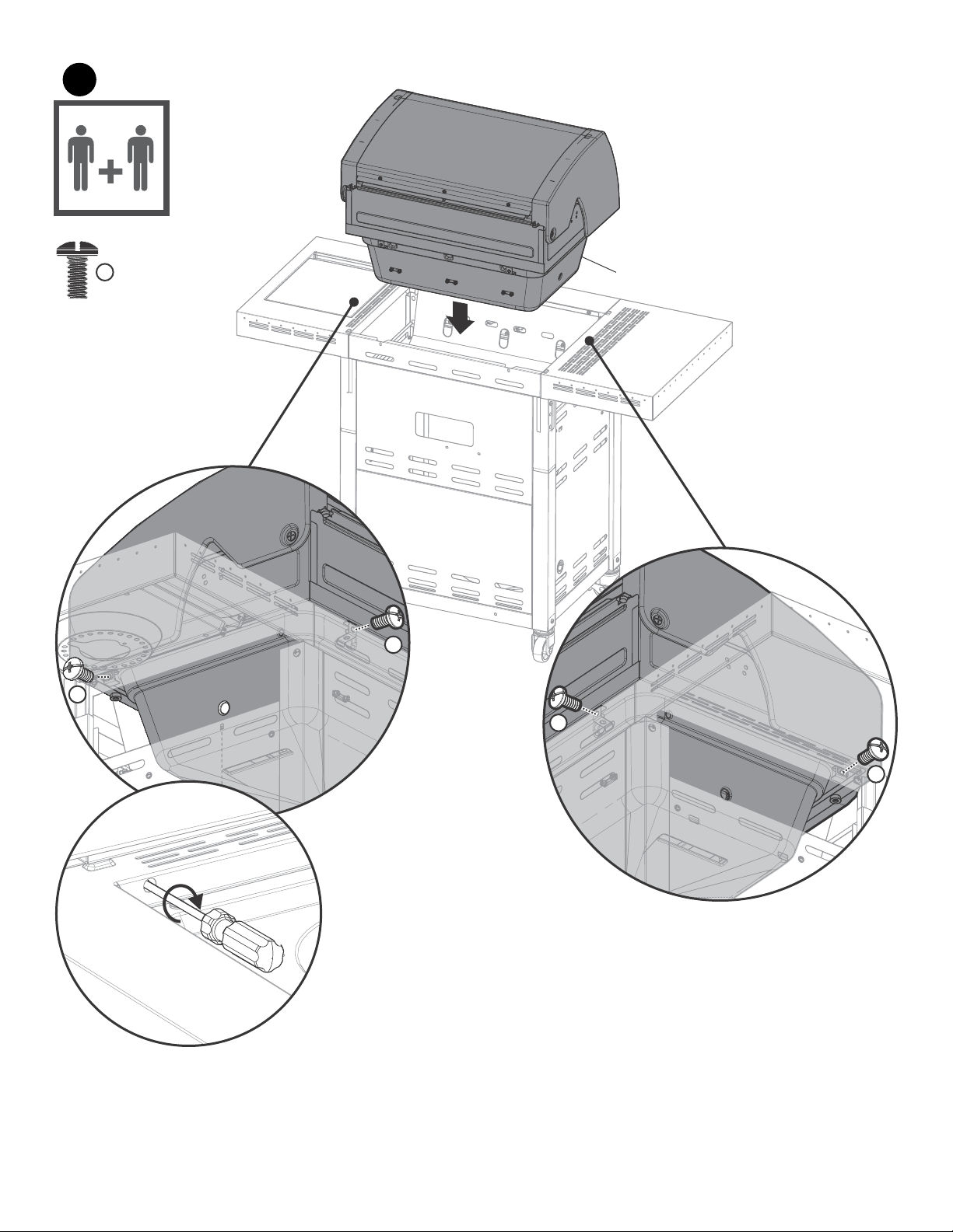
101FIREBOX
113BURNER BRACE
123MAIN BURNER TUBE, NO ELECTRODE
133
ELECTRODE SET, F/ MAIN BURNER
142FLAME CARRY OVER TUBE
151MAIN CONTROL PANEL, TOP
161MAIN CONTROL PANEL, BOTTOM
171HOSE VALVE REGULATOR
184CONTROL KNOB
194BEZEL, KNOB
201IGNITER SWITCH MODULE
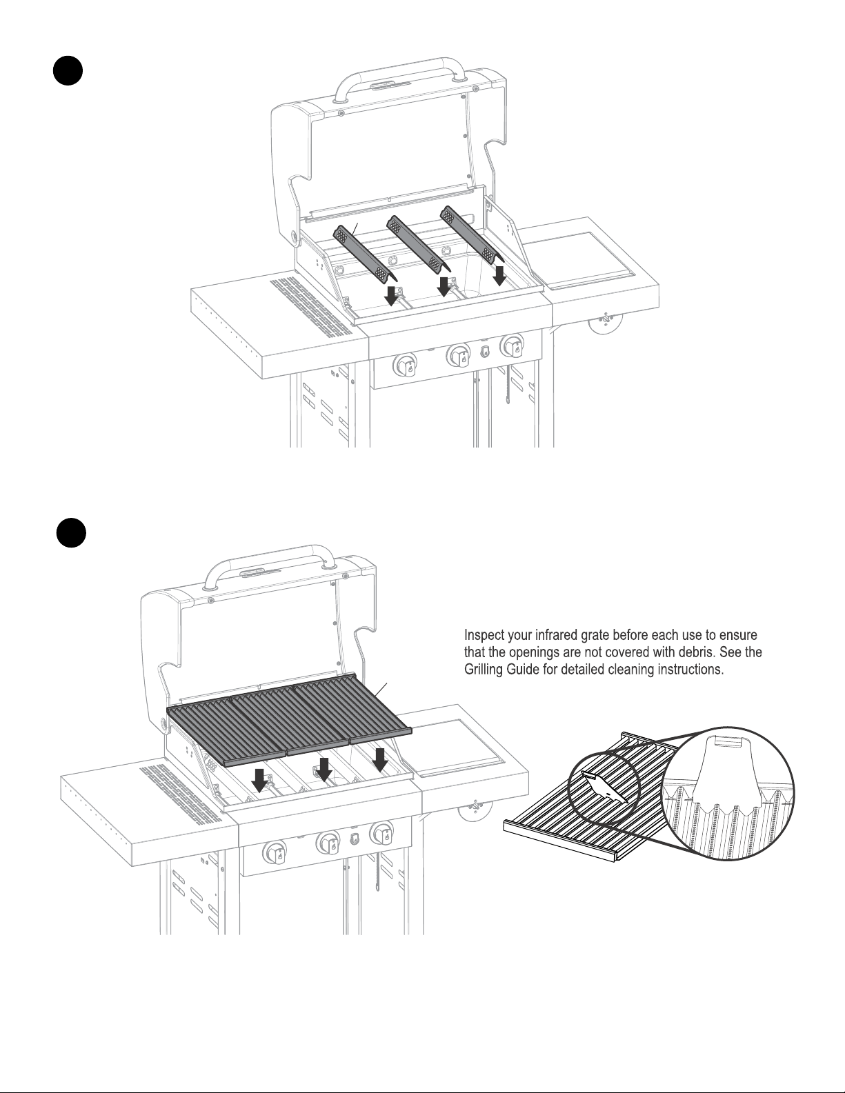
213HEAT TENT
221WARMING RACK
233COOKING GRATE
243COOKING GRATE, INFRARED EMITTER
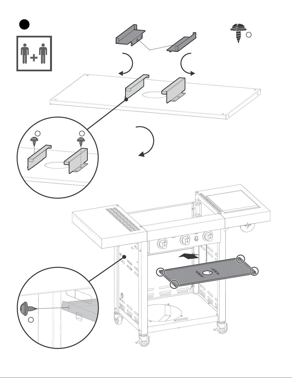
251BOTTOM SHELF
262TANK SUPPORT
272CASTER, LOCKING
282CASTER, FIXED
291LEFT TROLLEY ASSEMBLY
301MATCH HOLDER
311RIGHT TROLLEY ASSEMBLY
321GROMMET
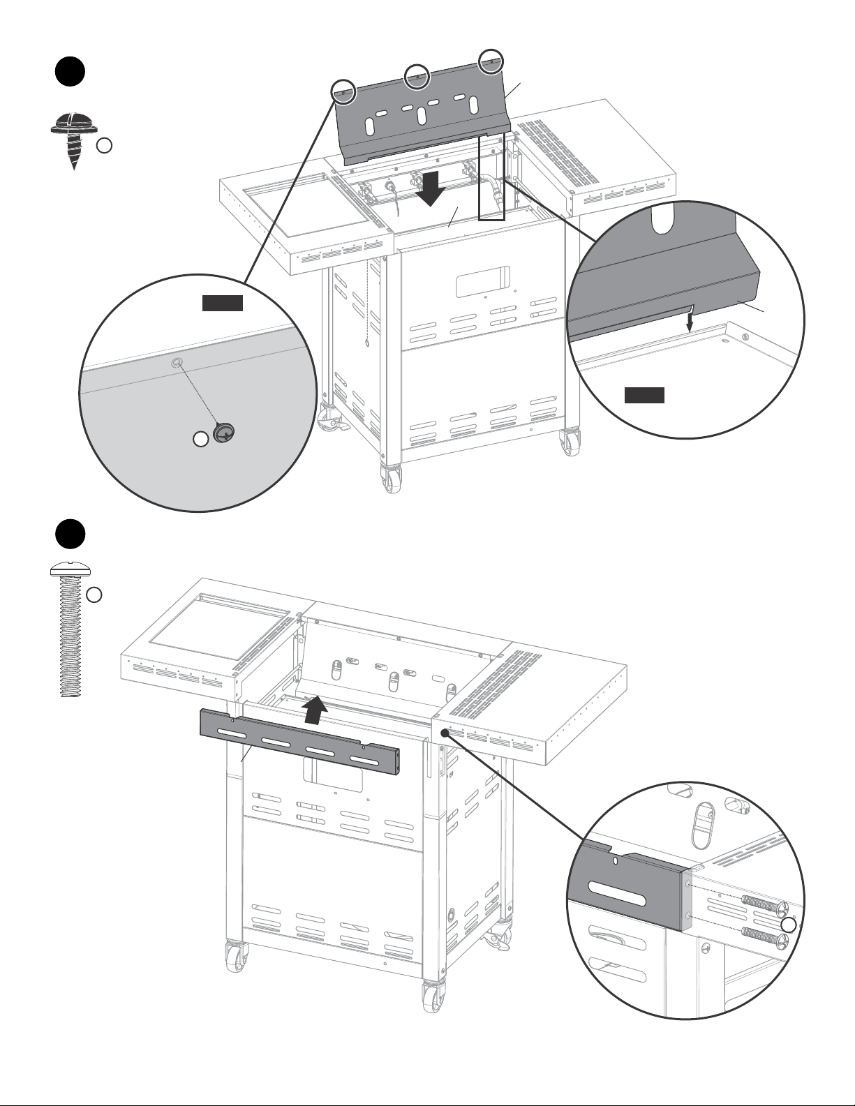
331REAR TROLLEY PANEL A
KeyQtyDescription
341REAR TROLLEY PANEL B
351UPPER REAR TROLLEY PANEL
361FRONT DOOR BRACE
374SIDE SHELF CONNECTION BRACE
382RAIL, F/ GREASE TRAY
391GREASE TRAY
401LEFT DOOR, NO HANDLE
411RIGHT DOOR, NO HANDLE
422HANDLE, F/ DOOR
434DOOR BUSHING, F/ HANDLE
441LEFT SIDE SHELF
451HOT PLATE SHELF
461DRIP PAN, F/ HOT PLATE
472SILICONE RUBBER BUMPER, F/ HOT PLATE
481HOT PLATE LID
491CONTROL PANEL, F/ HOT PLATE SHELF
501HOT PLATE
511ELECTRODE, F/ HOT PLATE
521WIRE, F/ HOT PLATE ELECTRODE
531HEAT SHIELD, FIREBOX
541HEAT SHIELD, F/ TANK
551GRATE, F/ HOT PLATE
561ELECTRONIC IGNITION MODULE
571CAP, F/ EI MODULE
581HEAT SHIELD, F/ IGNITION MODULE
591HOT PLATE
601FIREBOX SEPARATOR
NOT Pictured
…2MAGNET
…1PRODUCT GUIDE, AUSTRALIA
…1HARDWARE PACK
…1IR CLEANING TOOL
13
PARTS DIAGRAM
#9
#6
#5
#20
#57
#14
#1
#2
#3
#4
#7
#12
#13
#11
#58
#56
#21
#59
#8
#22
#23
#24
#15
#16
#50
#51
#17
#10
#19
#18
#49
#47
#35
#36
#55
#46
#48
#44
#39#38
#54
#43
#32
#42
#40
#29
#28
#27
#25
#53
#34
#30
#31
#41
#42
#26
#33
#45
#37
#52
#60
14
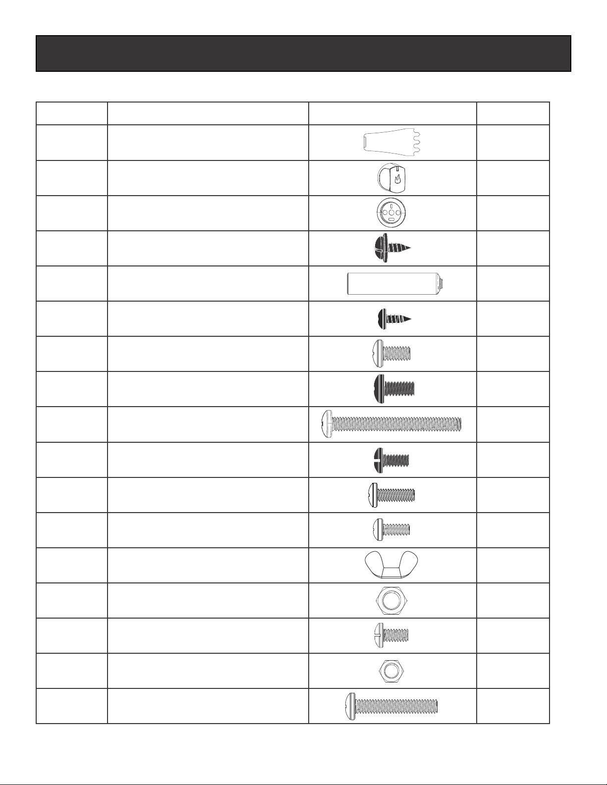
HARDWARE LIST
Hardware is shown actual size. You may have spare hardware after assembly is complete.
KeyDescriptionPictureQty
A
B
C
D
E
F
G
H
K
P
1/4-20x1 ½” Screw
1/4-20x1/2” Screw
1/4" Nut
#8-32x3/8” Screw
#8x3/8" self-tapping Screw
M4 Wing Nut
L
J
Knob
Bezel, Knob
4
20
4
4
2
9
1
1
8
3
1
M
1
Cleaning Tool
1/4-20x2-3/8” Screw
6
#10-24x3/8” Screw
N
#10-24 Nut
1
R
#10-24x3/4” Screw4
#10-24x3/8” Screw(Black)
1/4-20x1/2” Screw(Black)
#8x3/8" self-tapping Screw(Black)
T
14
S
1
AA Battery
-
+
15
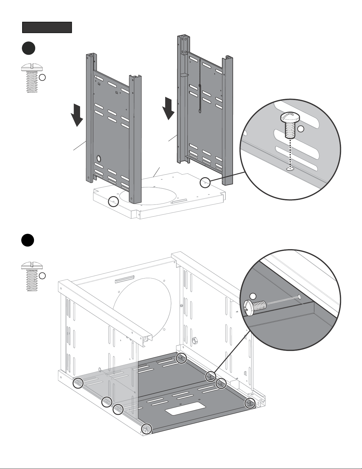
ASSEMBLY
2
1
G
x2
G
x8
G
G
#31
#25
#29
#33
#34
16
33
1ST
2ND
R
x1
S
x1
G
x4
R
S
G
#26
#26
#25
#25
#26
17
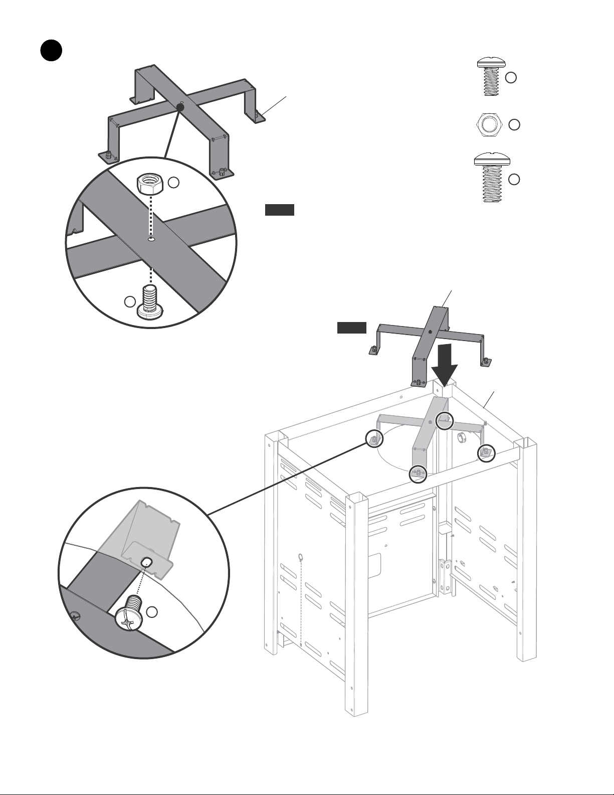
4
5
#28
P
x4
J
x4
J
P
H
x4
H
#28
#28
#27
#27
#37
#37
18
6
7
1ST
2ND
R
x2
J
x2
G
x6
R
R
G
G
G
J
#45
#49
#45
#44
#16
#15
#17
#15
#16
19
8
D
x6
D
D
D
#38
#54
20
9
10
2ND
1ST
D
x3
D
T
x4
T
#53
#54
#53
#53
#54
#35
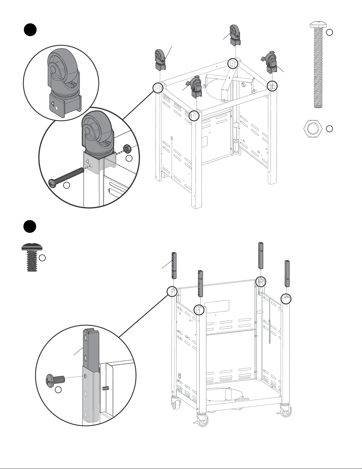
21
11
K
x4
#10
#10
#10
#45
#44
#45
K
K
K
K

22
12
1ST
2ND
3RD
Before
After
WARNING
Burner must properly engage valve as
shown. Failure to engage valve as shown
may result in personal injury and/or
property damage.
#12
#13
#14
23
13
14
#21
#24
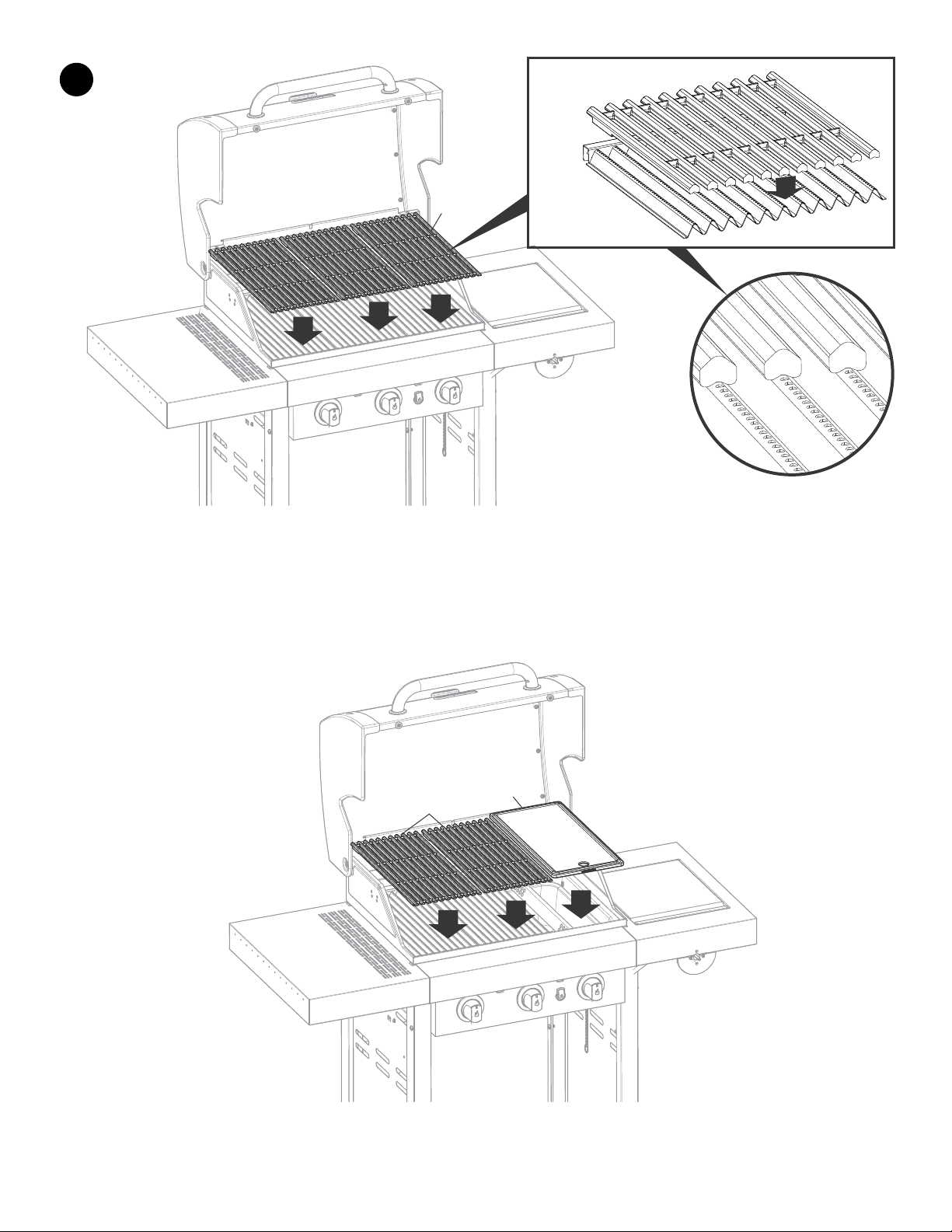
24
15
OR
#23
#23
#59
25
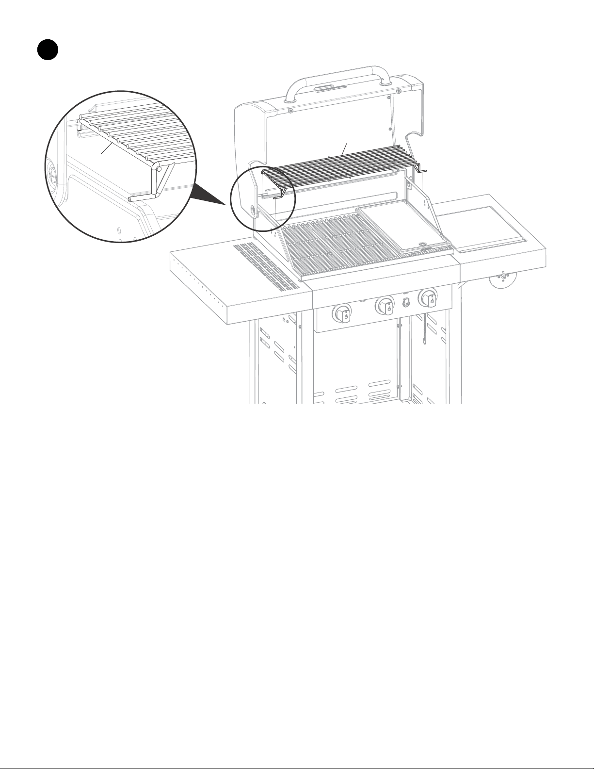
16
#22
#22
#10
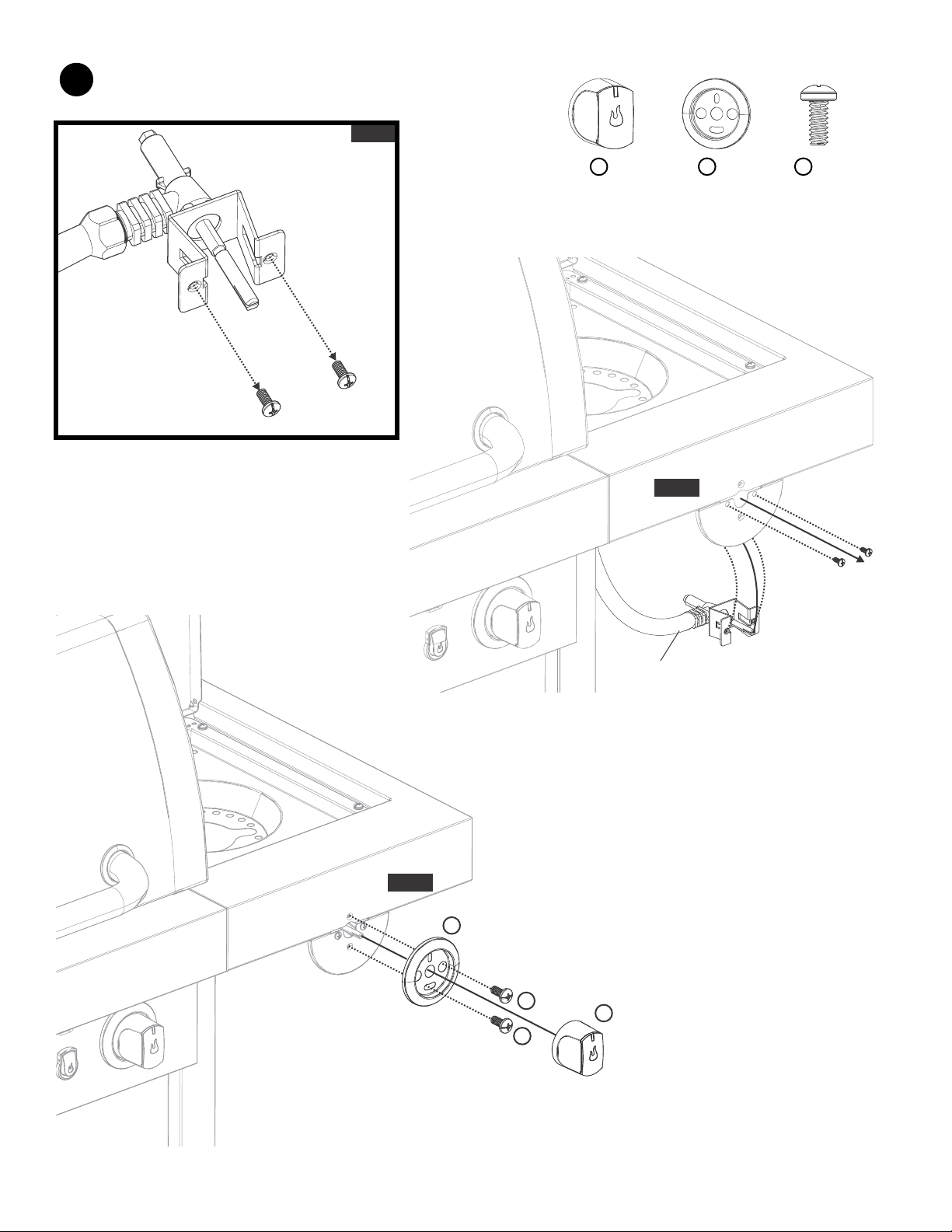
26
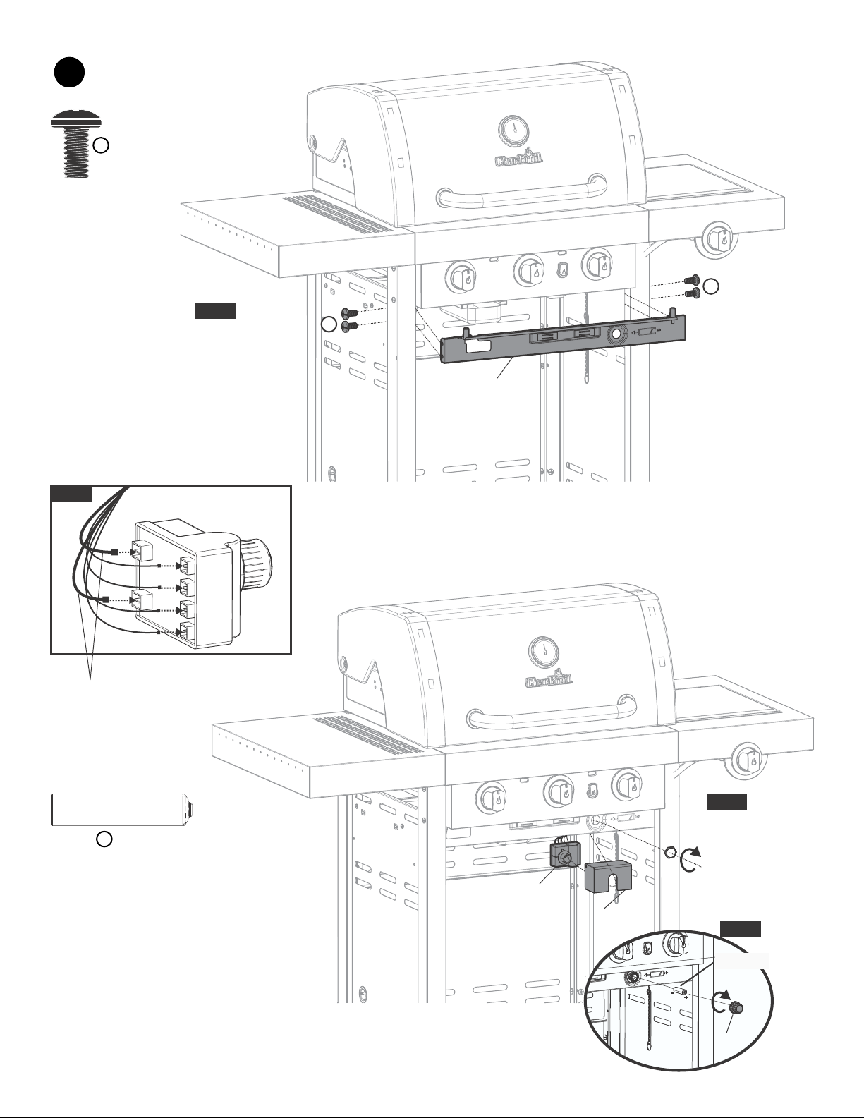
B
x1
C
x1
M
x2
17
2ND
3RD
1ST
Remove screws and washers
Enlevez les vis et rondelles
Retire los tornillos y arandelas
#17
B
C
M
M
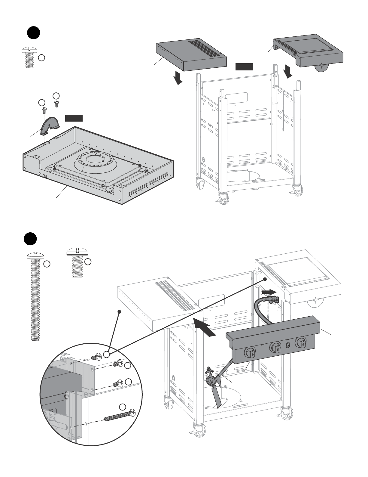
27
18
19
N
x1
N
#50
#51
#50
#51
#55
28
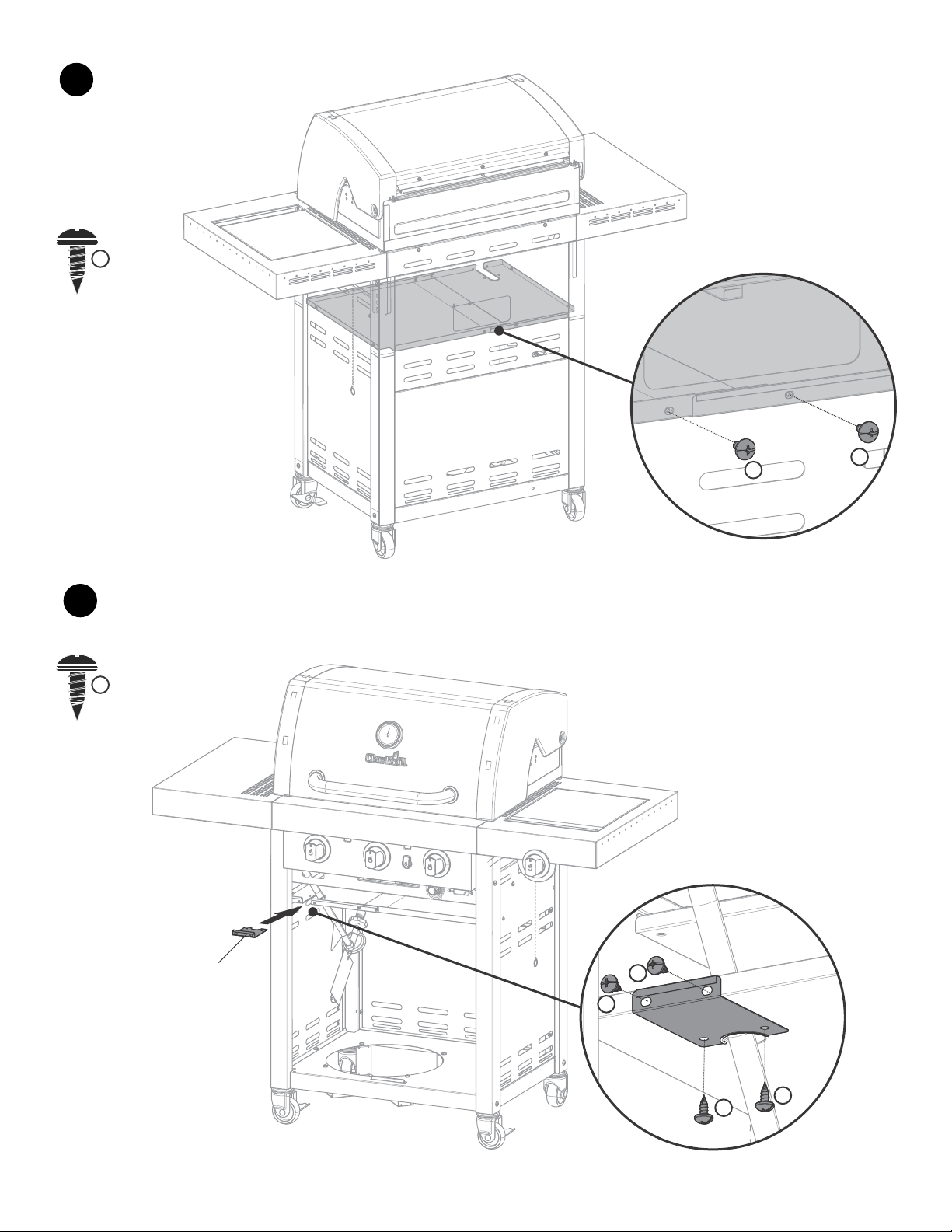
20
H
x4
-
+
E
x1
20
1ST
3RD
2ND
H
H
#36
#56
#58
#20
#57
AA Battery
4TH

29
21
22
1ST
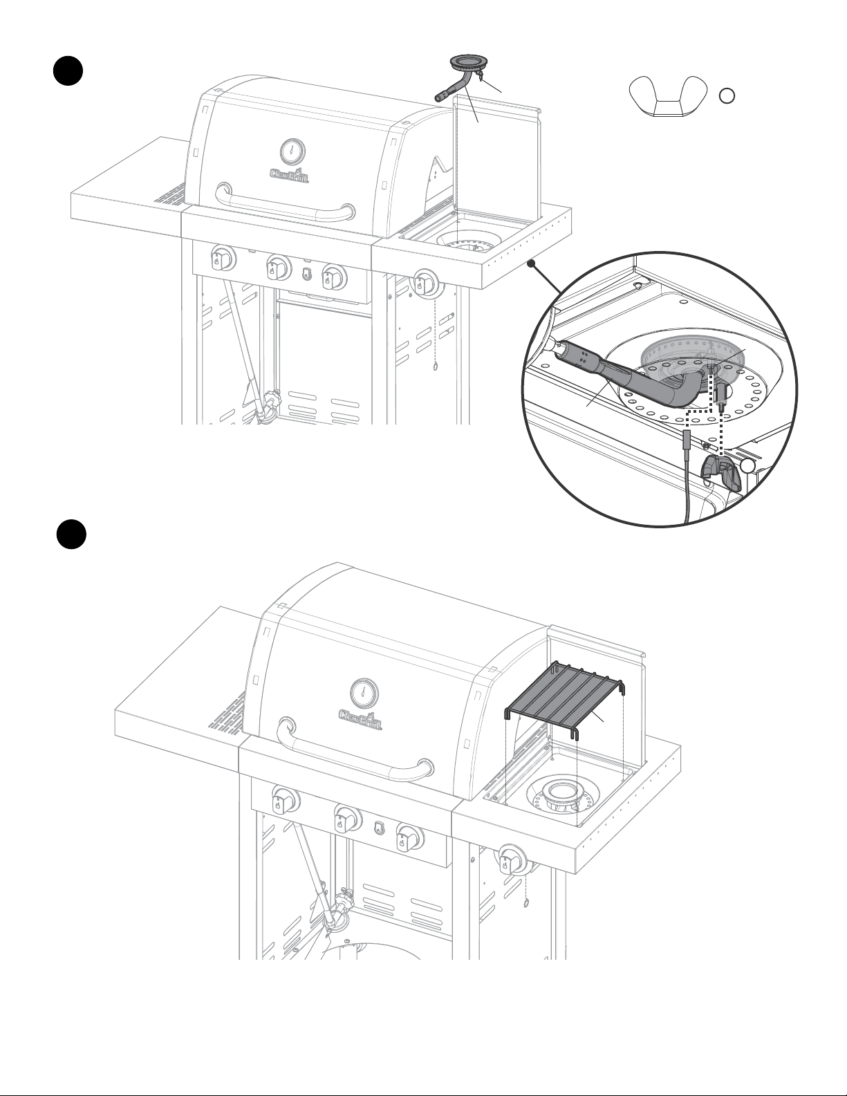
2ND
F
x2
F
x6
3RD
#60
#60
F
F
F
F
F
F
F
F
30
23
24
F
x2
F
x4
F
F
#60
F
F
F
F
31
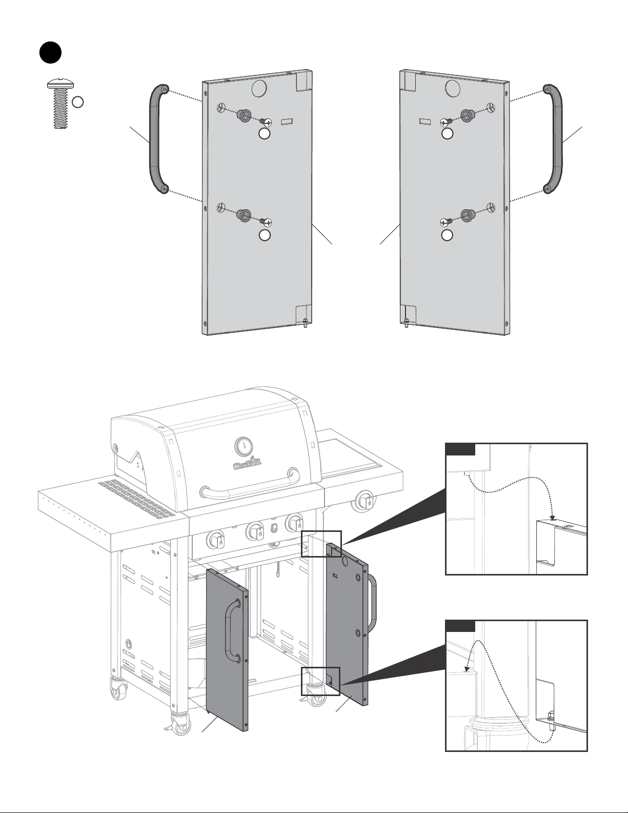
25
1ST
2ND
L
L
#42
#41
L
x4
#41
#40
L
L
#42
#40
32
26
27
A
x1
A
#39
33
28
34
NATURAL GAS CONVERSION
TO BE INSTALLED ONLY ON OR IN A NON-
COMBUSTIBLE ENCLOSURE
Note: Recommended clearances must be maintained,
see page 4.
1.
Servicing Instructions
Appliances should be serviced at least annually and
servicing must only be carried out by a Licensed Plumber
or Authorised Person.
Clean the Burner Ports and top with a Soft Brush.
Inspect and clean all combustion air inlets, then replace
the Burner ensuring it is firmly secured.
NATURAL GAS CONVERSION ONLY TO BE DONE
BY AN AUTHORISED PERSON OR LICENSED
PLUMBER.
Improper installation, adjustment, alteration, service
or maintenance can cause injury or property damage.
Read the instructions thoroughly before installing or
servicing this equipment.
This appliance must not be installed or used indoors.
The authorised person will provide a certificate of
compliance.
An AGA approved natural gas pressure regulator
must be installed in the pipeline and be set at 1 kPa.
WARNING
4. Installation of a drip leg if required in the supply line
must conform to AS5601.
Warning: Improper installation, adjustment, alteration,
service or maintenance can cause injury or property
damage. Read the instructions thoroughly before
installing or servicing this equipment.
6. Installation of 1/8” NPT plugged tapping, accessible
for test gauge connections, is required upstream of
the gas supply connection.
5. When checking for gas leaks, do not use an open
flame. Use a soap and water solution and check for
bubbles indicating gas leakage.
3. All gas pipe connections must be sealed with a
gas pipe compound resistant to Natural Gas.
2. Check with local and state plumbing and heating
codes regarding sizing of the gas lines.
(b) Where it is not practical to install solid tube
AGA certified stainless steel braided hose can
be installed. This hose assembly must comply
with AS5601 Gas Installations, pipe sizing
tables and shall not exceed 3 metres in length.
The internal diameter of the hose must not be
less than the 10mm.
(a) A minimum pipe diameter of 15mm is required
for inlet piping. A lever operated shut-off valve
should be installed within 1 metre of the
appliance for servicing the unit.
Gas Piping
(c) Chain or wire of adequate strength must be
fixed to the appliance. Only one end to the
appliance, the other end to be securely
anchored to wall or floor. The length of the
chain or wire is not to exceed 80% of the length
of the gas assembly.
(d) Tools are required to assemble the
Conversion Kit.
2 adjustable spanners
7 mm scoket
Specification Natural Gas
Gas consumption @ 1.0kPA
Injector sizeInjector size
Main burners - 1.43 mm
Side burner - 1.90 mm
3 main burners at 8.43 MJ/h each
1 side burner at 13.7 MJ/h
Total 39.0 MJ/h

35
Appliance conversion - Main Burners
1.Remove cooking grate, hot plate, and heat tents.
2.Remove clips retaining flame carryover tubes and burners.
3.Remove flame carryover tubes and burners.
4.Using a 7 mm nut drive remove LP orifices and save in case barbecue needs to be converted
back to LP.
5.Remove control knobs and screws and washers (Shown below). Only do one
control knob at a time.
6.Install NG bezel plates supplied in hardware pack using screws and washer removed In step 5
and replace control knobs (shown below).
7.Replace burners, flame carryover tubes, retaining clips, heat tents, cooking grate and hot plate.
Appliance conversion - Side Burner
1.Remove side burner.
2.Using a 7 mm nut drive remove LP orifices and save in case barbecue needs to be converted
back to LP.
3.Remove control knobs and screws and washers (Shown below).
4.Install NG bezel plates supplied in hardware pack using screws and washer removed in step 3
and replace control knobs (shown below).
5.Replace side burner.
NG Bezel
TEST OPERATION OF APPLIANCE BEFORE LEAVING
Remove knob and screws/washers
Install NG Bezel, screws/washers and knob
36
EMERGENCIES: If a gas leak cannot be stopped, or a fire occurs due to gas leakage, call the fire department.
Emergencies
Problem
Gas leaking from
cracked/cut/burned hose.
Gas leaking from LP cylinder.
Gas leaking from LP
cylinder valve.
Gas leaking between LP
cylinder and regulator
connection.
Fire coming through control
panel.
Grease fire or continuous
excessive flames above
cooking surface.
Burner(s) will not light
using ignitor.
(See Electronic Ignition
Troubleshooting also)
Continued on next page.
Possible Cause
Possible Cause
• Damaged hose.
• Mechanical failure due to rusting or mishandling.
• Failure of cylinder valve from mishandling or
mechanical failure.
• Fire in burner tube section of burner due to blockage.
• Too much grease buildup in burner area.
GAS ISSUES:
• Trying to light wrong burner.
• Burner not engaged with control valve.
• Obstruction in burner.
• No gas flow.
• Coupling nut and LP cylinder valve not fully
connected.
ELECTRICAL ISSUES:
• Electrode cracked or broken; “sparks at crack.”
• Electrode tip not in proper position.
(Does not apply to SUREFIRE.)
• Wire and/or electrode covered with cooking residue.
• Wires are loose or disconnected.
• Wires are shorting (sparking) between ignitor and
electrode.
• Dead battery.
Prevention/Solution
Prevention/Solution
• Replace LP cylinder.
• Turn off LP cylinder valve. Return LP cylinder to gas supplier.
• Turn off control knobs and LP cylinder valve. Leave lid open to allow flames to die
down. After fire is out and grill is cold, remove burner and inspect for spider nests or
rust. See Natural Hazard and Cleaning the Burner Assembly pages.
• Turn off control knobs and LP cylinder valve. Leave lid open to allow flames to die
down. After cooling, clean food particles and excess grease from inside firebox area,
grease tray, and other surfaces.
• See instructions on control panel and in Use and Care section.
• Make sure valves are positioned inside of burner tubes.
• Ensure burner tubes are not obstructed with spider webs or other matter. See
cleaning section of Use and Care.
• Make sure LP cylinder is not empty. If LP cylinder is not empty, refer to
“Sudden drop in gas flow.”
• Turn the coupling nut approximately one-half to three-quarters additional turn until
solid stop. Tighten by hand only - do not use tools.
• Replace electrode(s).
Main Burners:
• Tip of electrode should be pointing toward gas port opening on burner. The
distance should be 1/8” to 1/4”. Adjust if necessary.
Sideburner:
• Tip of electrode should be pointing toward gas port opening on burner. the
distance should be 1/8” to 3/16”. Adjust if necessary.
• Clean wire and/or electrode with rubbing alcohol and clean swab.
• Reconnect wires or replace electrode/wire assembly.
• Replace ignitor wire/electrode assembly.
• Replace with a new alkaline battery.
Troubleshooting
Burner(s) will not match light.
ELECTRONIC IGNITION:
• No spark, no ignition noise.
• No spark, some ignition noise.
• Sparks, but not at electrode or at full strength.
• See “GAS ISSUES:” .
• Match will not reach.
• Improper method of match-lighting.
• See Section I of Electronic Ignition System.
• See Section II of Electronic Ignition System.
• See Section III of Electronic Ignition System.
• Use long-stem match (fireplace match).
• See “Match-Lighting” section of Use and Care.
•Turn off gas at LP cylinder or at source on natural gas systems. Discontinue use of
product and replace hose/regulator. Once hose/regulator is replaced conduct
complete leak check per manual.
• Improper installation, connection not tight, and/or
failure of rubber seal in clyinder valve.
•Turn off LP cylinder valve. Remove regulator from cylinder and visually inspect rubber
seal in cylinder valve for damage. If damage or cannot correct leak replace cylinder.
See LP Cylinder Leak Test and Connecting Regulator to the LP Cylinder.
37
Troubleshooting (continued)
Problem
Sudden drop in gas flow or
low flame.
Flames blow out.
Flare-up.
Persistent grease fire.
Flashback (fire in
burner tube(s)).
One burner does not light
from other burner(s).
Possible Cause
• Out of gas.
• Excess flow valve tripped.
• Vapor lock at coupling nut/LP cylinder connection.
• High or gusting winds.
• Low on LP gas.
• Excess flow valve tripped.
• Grease buildup.
• Excessive fat in meat.
• Excessive cooking temperature.
• Grease trapped by food buildup around
burner system.
• Burner and/or burner tubes are blocked.
• Grease buildup or food particles in end(s) of
carryover tube(s).
Prevention/Solution
• Check for gas in LP cylinder.
• Turn off knobs, wait 30 seconds and light grill. If flames are still low, turn off knobs
and LP cylinder valve. Disconnect regulator. Reconnect regulator and leak-test. Turn
on LP cylinder valve, wait 30 seconds and then light grill.
• Turn off knobs and LP cylinder valve. Disconnect coupling nut from cylinder.
Reconnect and retry.
• Refill LP cylinder.
• Refer to “Sudden drop in gas flow” above.
• Clean burners and inside of grill/firebox.
• Trim fat from meat before grilling.
• Adjust (lower) temperature accordingly.
• Turn knobs to OFF. Turn gas off at LP cylinder. Leave lid in position and let fire
burn out. After grill cools, remove and clean all parts.
• Turn knobs to OFF. Clean burner and/or burner tubes. See burner cleaning
section of Use and Care.
• Clean carry-over tube(s) with wire brush.
Troubleshooting - Electronic Ignition
Problem (Ignition)
SECTION I
No sparks appear at any
electrodes when Electronic
Ignition Button is pressed;
no noise can be heard from
spark module.
SECTION II
SECTION III
Sparks are present but not at
all electrodes and/or not at
full strength
Possible Cause
• Battery not installed properly.
• Dead battery.
• Button assembly not
installed properly.
• Faulty spark module.
• Output lead connections not
connected.
• Output lead connections not
connected.
• Arcing to grill away from
burner(s).
• Weak battery.
• Electrodes are wet.
• Electrodes cracked or broken
“sparks at crack”.
Check Procedure
• Check battery orientation.
• Has battery been used previously?
• Check to insure threads are properly
engaged. Button should travel up and
down without binding.
• If no sparks are generated with new
battery and good wire connections,
module is faulty.
• Are output connections on and tight?
• Are output connections on and tight?
• If possible, observe grill in dark
location. Operate ignition system and
look for arcing between output wires
and grill frame.
• All sparks present but weak or at
slow rate.
• Has moisture accumulated on electrode
and/or in burner ports?
• Inspect electrodes for cracks.
Prevention/Solution
• Install battery (make sure that “+” and “–” connectors are
oriented correctly, with “+” on cap end.)
• Replace battery with new alkaline battery.
• Unscrew button cap assembly and reinstall, making sure
threads are aligned and engaged fully.
• Replace spark module assembly.
• Remove and reconnect all output connections at module and
electrodes.
• Remove and reconnect all output connections at module and
electrodes.
• If sparks are observed other than from burner(s), wire insulation
may be damaged. Replace wires.
• Replace battery with a new alkaline battery.
• Use paper towel to remove moisture.
• Replace cracked or broken electrodes.
No sparks appear at any
electrodes when Electronic
Ignition Button is pressed;
noise can be heard from spark
module.
•Turn front of grill to face wind or increase flame height by turning gas valve to a
higher postion.

38

39

40
.
For use with propane gas only ● For Outdoor Use Only
DO NOT USE INDOORS.
AGA 8544 G
For support with your new barbecue, please call us at:
Amalgamated Hardware Merchants
Ph: 07 3208 1233
Email: [email protected]