Owner's Manual
CRRFTSMRN°
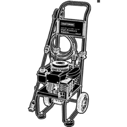
5.5 HORSEPOWER
2,000 PSI
2.0 GPM
HIGH PRESSUR
Model No. 580.768210
WASHER
HOURS: Mon.- Fri. 8 a.m. to 5 p.m. (CT)
CAUTION" Before using this product,
read this manual and follow all Safety
Rules and Operating Instructions.
• Safety
• Assembly
• Operation
• Maintenance
• Parts
• Espafiol
SEARS, ROEBUCK and CO., Hoffman Estates, IL 60179 U.S.A.
Visit our Craftsman website: www.sears.com/craftsman
Part No. B5655 Draft 3 (6/2/2000)
WARRANTY ................................... 2
SAFETY RULES .............................. 2-3
ASSEMBLY .................................. 4-5
OPERATION ................................. 6-9
MAINTENANCE ............................. 9-12
SPECIFICATIONS ............................. 10
STORAGE ................................... 13
TROUBLESHOOTING .......................... 14
REPLACEMENT PARTS ...................... 16-23
EMISSION CONTROL WARRANTY ................ 24
ESPANOL ................................. 25-39
HOW TO ORDER PARTS ............... BACK PAGE
LIMITED WARRANTY ON CRAFTSMAN HIGH PRESSURE WASHER
For one year from the date of purchase, when this Craftsman pressure washer is maintained and operated
according to the instructions in the owner's manual, Sears will repair, free of charge, any defect in material and
workmanship.
If this washer is used for commercial purposes, this warranty applies for only 90 days from the date of purchase.
If this high pressure washer is used for rental purposes, this warranty applies for only 30 days after date of
purchase.
This warranty does not cover:
• Expendable items such as spark plugs or air filters, which become worn during normal use.
• Repairs necessary because of operator abuse or negligence, including damage resulting from no water being
supplied to pump or failure to maintain the equipment according to the instructions contained in the owner's
manual.
Warranty service is available by returning the high pressure washer to the nearest Sears service center or dealer
in the United States.
This warranty gives you specific legal rights and you may also have other rights, which vary from state to state.
Sears, Roebuck and Co., Dept. 817WA, Hoffman Estates, IL 60179
The engine exhaust from this product contains
chemicals known to the State of California to
cause cancer, birth defects, or other
reproductive harm.
CAUTION! When setting up, transporting,
adjusting or making repairs to your high
pressure washer, always disconnect the spark
plug wire from the spark plug and place the wire
where it cannot contact spark plug.
DANGER! Engine exhaust gases contain
DEADLY carbon monoxide gas. This dangerous
gas, if breathed in sufficient concentrations, can
cause unconsciousness or even death. Operate
this equipment only in the open air where
adequate ventilation is available.
,_ DANGER! Gasoline is highly FLAMMABLE
and its vapors are EXPLOSIVE. Do Not permit
smoking, open flames, sparks or heat in the
vicinity while handling gasoline. Avoid spilling
gasoline on a hot engine. Allow unit to cool
before refueling. Comply with all laws regulating
storage and handling of gasoline.
Read this manual carefully and become familiar
with your pressure washer. Know its applications,
its limitations, and any hazards involved.
• Locate this pressure washer in areas away from
combustible materials, combustible fumes or dust.
• The high pressure equipment is designed to be
used with Sears authorized parts ONLY. If you use
this equipment with parts that do not comply with
minimum specifications, the user assumes all risks
and liabilities.
• Somechemicalsordetergentsmaybeharmfulif
inhaledor ingested,causingseverenausea,
faintingor poisoning.Theharmfulelementsmay
causepropertydamageorsevereinjury.
• DoNotallowCHILDRENtooperatethepressure
washerat anytime.
• Operateengineonlyatgovernedspeed.Running
theengineatexcessivespeedsincreasesthe
hazardof personalinjury.DoNottamperwithparts
whichmayincreaseordecreasethegoverned
speed.
• DoNotwearlooseclothing,jewelryoranything
thatmaybecaughtin thestarterorotherrotating
parts.
• Beforestartingthepressurewasherincold
weather,checkall partsoftheequipmentandbe
sureicehasnotformedthere.
• Neverusea spraygunwhichdoesnothavea
triggerlockortriggerguardin placeandinworking
order.
• Keepthehoseconnectedto machineorthespray
gunwhilethesystemispressurized.Disconnecting
thehosewhiletheunitispressurizedisdangerous.
• Unitswithbrokenor missingparts,orwithout
protectivehousingorcovers,shouldNeverbe
operated.
• Checkthefuelsystemforleaksorsignsof
deterioration,suchaschafedorspongyhose,
looseormissingclamps,ordamagedtankorcap.
Correctalldefectsbeforeoperatingthepressure
washer.
• DoNotsprayflammableliquids.
• Usea respiratorormaskwheneverthereisa
chancethatvaporsmaybeinhaled.Readall
instructionswithmasksoyouarecertainthemask
willprovidethenecessaryprotectionagainst
inhalingharmfulvapors.
• Neveraimthespraygunat people,animalsor
plants.Thehighpressurestreamofwaterthatthis
equipmentproducescanpierceskinandits
underlyingtissues,leadingto seriousinjuryand
possibleamputation.
• Neverallowanypartofthebodytocomein
contactwiththefluidstream.DoNotcomein
contactwithafluidstreamcreatedbyaleakinthe
highpressurehose.
• Alwaysweareyeprotectionwhenyouusethis
equipmentorwhenyouareinthevicinitywhere
theequipmentisinuse.
• Highpressurespraycancausepaintchipsorother
particlesto becomeairborne.
• DoNotoperatethepressurewasherabovethe
ratedpressure.
• Nevermovethemachinebypullingonthehigh
pressurehose.Usethehandleprovidedonthe
unit.
• Alwaysbecertainthespraygun,nozzlesand
accessoriesarecorrectlyattached.
• DoNotsecurethesprayguninthe(open)
position.
• Highpressurespraymaydamagefragileitems
includingglass.DoNotpointspraygunat glass
wheninthejetspraymode.
• Holdthespraygunfirmlyinyourhandbeforeyou
starttheunit.Failureto dosocouldresultinan
injuryfromawhippingspraygun.Do Notleavethe
spraygununattendedwhilethemachineis
running.
• Thecleaningareashouldhaveadequateslopes
anddrainageto reducethepossibilityofafalldue
to slipperysurfaces.
• Keepwatersprayawayfromelectricwiringorfatal
electricshockmayresult.
• DoNotby-passanysafetydeviceonthis
machine.
• Themufflerandengineheatupduringoperation
andremainhotimmediatelyaftershuttingitdown.
Avoidcontactwithahotmufflerorengineasyou
couldbeseverelyburned.
• Operateandstorethisunitona stablesurface.
• Highpressurehosecandevelopleaksfromwear,
kinking,abuse,etc.Watersprayingfroma leakis
capableof injectingmaterialintoskin.Inspecthose
eachtimebeforeusingit.Checkallhosesforcuts,
leaks,abrasionsorbulgingof cover,ordamageor
movementof couplings.Ifanyof theseconditions
exist,replacehoseimmediately.Neverrepairhigh
pressurehose.Replaceitwithanotherhosethat
meetsmaximumpressureratingofyourunit.
• Themufflerandaircleanermustbeinstalledandin
goodconditionbeforeoperatingthepressure
washer.Thesecomponentsactassparkarresters
iftheenginebackfires.
IntheStateof Californiaa sparkarresterisrequired
bylaw(Section4442oftheCaliforniaPublic
ResourcesCode).Otherstatesmayhavesimilarlaws.
Federallawsapplyonfederallands.
NOTE:Ifyouequipthemufflerwitha sparkarrester,it
mustbemaintainedin effectiveworkingorder.You
canordera sparkarresterthroughyourauthorized
Searsservicedealer.
,_ THIS IS THE SAFETY ALERT SYMBOL. IT IS USED TO ALERT YOU TO POTENTIAL
PERSONAL INJURY HAZARDS. OBEY ALL SAFETY MESSAGES THAT FOLLOW THIS
SYMBOL TO AVOID POSSIBLE INJURY OR DEATH.
Your pressure washer requires some assembly and is
ready for use only after it has been properly serviced
with the recommended oil and fuel.
If you have any problems with the assembly of
your pressure washer, please call the pressure
washer helpline at 1-800-222-3136.
IMPORTANT: Any attempt to run the engine before it
has been serviced with the recommended oil will result
in an engine failure.
REMOVE PRESSURE WASHER
FROM CARTON
• Open carton and slice two corners opposite guide
handle from top to bottom so the panel can be
folded down flat.
• Remove fillers and parts box shipped with your
pressure washer.
• Roll the pressure washer out the open end of the
carton.
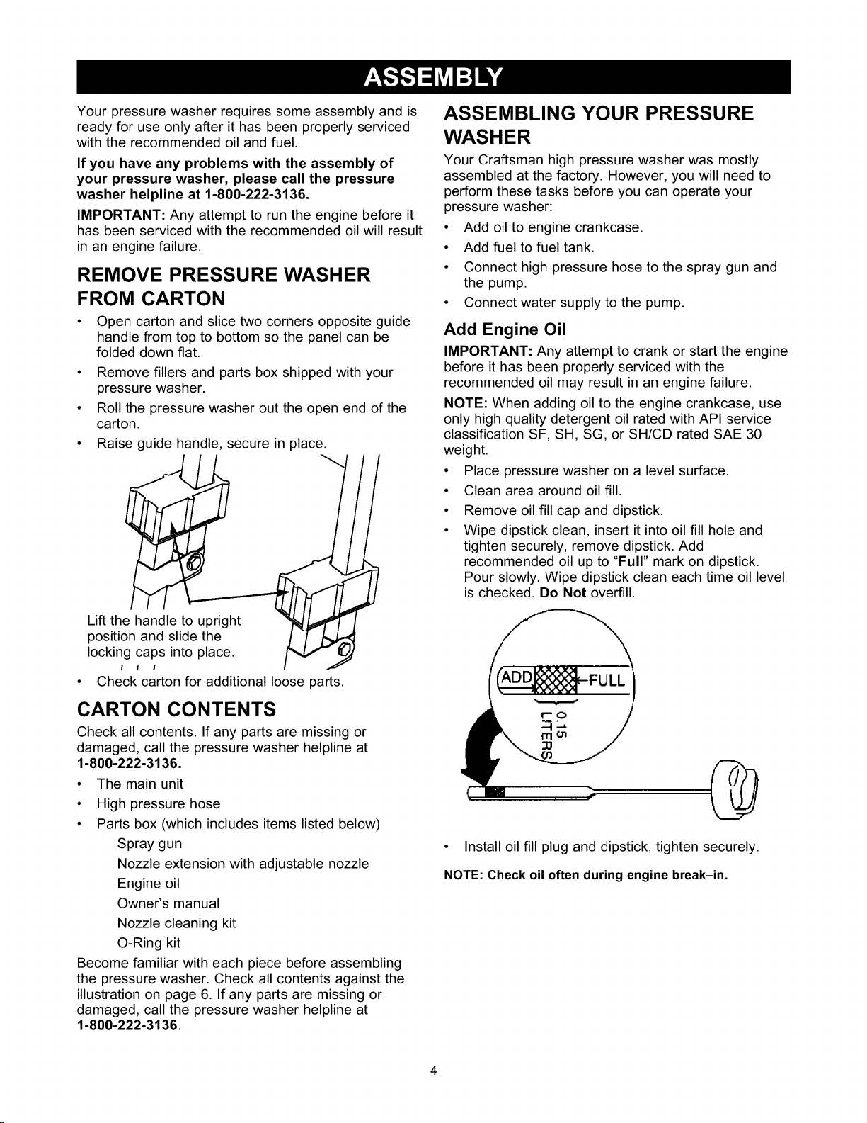
• Raise guide handle, secure in place.
Lift the handle to upright
position and slide the
locking caps into place.
I I I
• Check carton for additional loose parts.
CARTON CONTENTS
Check all contents. If any parts are missing or
damaged, call the pressure washer helpline at
1-800-222-3136.
• The main unit
• High pressure hose
• Parts box (which includes items listed below)
Spray gun
Nozzle extension with adjustable nozzle
Engine oil
Owner's manual
Nozzle cleaning kit
O-Ring kit
Become familiar with each piece before assembling
the pressure washer. Check all contents against the
illustration on page 6. If any parts are missing or
damaged, call the pressure washer helpline at
1-800-222-3136.
ASSEMBLING YOUR PRESSURE
WASHER
Your Craftsman high pressure washer was mostly
assembled at the factory. However, you will need to
perform these tasks before you can operate your
pressure washer:
• Add oil to engine crankcase.
• Add fuel to fuel tank.
• Connect high pressure hose to the spray gun and
the pump.
• Connect water supply to the pump.
Add Engine Oil
IMPORTANT: Any attempt to crank or start the engine
before it has been properly serviced with the
recommended oil may result in an engine failure.
NOTE: When adding oil to the engine crankcase, use
only high quality detergent oil rated with API service
classification SF, SH, SG, or SH/CD rated SAE 30
weight.
• Place pressure washer on a level surface.
• Clean area around oil fill.
• Remove oil fill cap and dipstick.
• Wipe dipstick clean, insert it into oil fill hole and
tighten securely, remove dipstick. Add
recommended oil up to "Full" mark on dipstick.
Pour slowly. Wipe dipstick clean each time oil level
is checked. Do Not overfill.
• Install oil fill plug and dipstick, tighten securely.
NOTE: Check oil often during engine break-in.

Add Gasoline
_ DANGER! Never fill fuel tank indoors. Never
fill fuel tank when engine is running or hot. Do
Not smoke when filling fuel tank.
_ ARNING! Never fill fuel tank completely full.
Provide space for fuel expansion. Wipe away
any fuel spillage from engine and equipment
before starting.
• Use fresh, clean unleaded automotive gasoline and
store in approved, clean, covered containers. Use
clean fill funnels. Never use "stale" gasoline left
over from last season or gasoline stored for long
periods.
• Clean area around fuel fill cap, remove cap.
• Slowly add "UNLEADED" regular gasoline to fuel
tank. Use a funnel to prevent spillage. Slowly fill
tank to about 1/2" below the bottom of the filler
neck.
/ 1/2" Air Space Tank
• Install fuel cap and wipe up any spilled gasoline.
Connect Hose and Water Supply to Pump
IMPORTANT: You must attach all hoses before you
start engine. Starting engine without all hoses
connected and water supplied will damage pump.
• Uncoil high pressure hose and attach one end of
hose to the base of the spray gun. Tighten by
hand.
• Attach other end of high pressure hose to the high
pressure outlet on the pump. Tighten by hand.
• Before you connect your garden hose to the water
inlet, inspect the inlet screen. Clean the screen if it
contains debris or have it replaced if damaged. Do
Not run the pressure washer if the inlet screen
is damaged.
• Connect garden hose to water inlet. Tighten by
hand.
_ ARNING! There MUST be at least ten feet of
unrestricted garden hose between the pressure
washer inlet and any flow shut off device, such
as a 'Y' shut-off connector or other
convenience-type water shut-off valve. Damage
to pressure washer resulting from disregarding
this warning will not be covered by the warranty.
• Turn ON the water (open supply valve completely).
_ AUTION! Before starting the pressure
washer, be sure you are wearing adequate
eye protection.
CHECKLIST BEFORE STARTING
ENGINE
Review the unit to ensure you have performed all of
the following:
• Check that oil has been added to proper level in
engine crankcase.
• Add proper gasoline to fuel tank.
• Check for properly tightened hose connections
(high pressure and water supply) and that there are
no kinks, cuts, or damage to the high pressure
hose.
• Provide proper water supply (not to exceed 140°F).
• Be sure to read "Safety Rules" and "Operation"
sections before using the pressure washer.
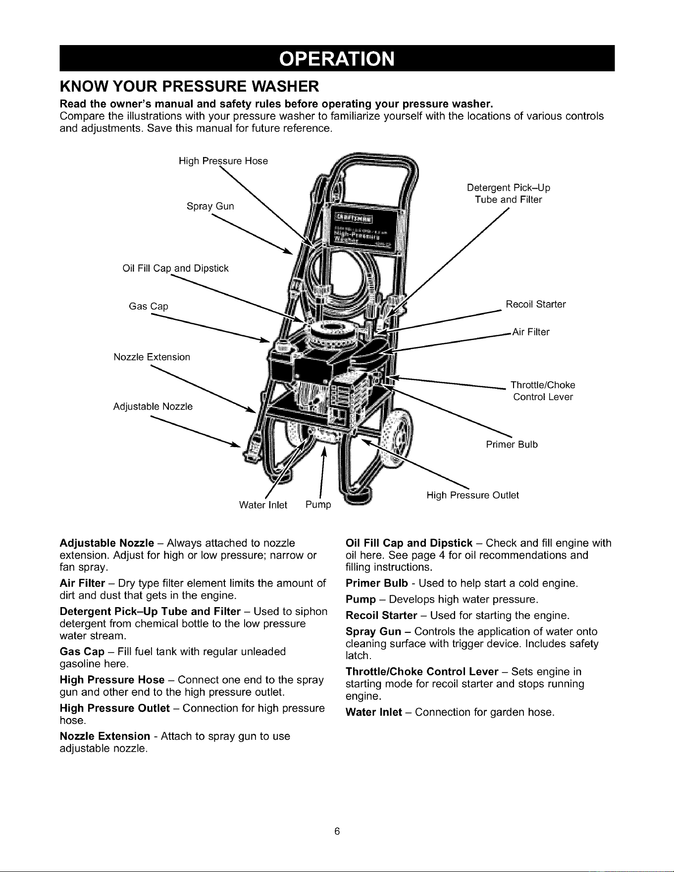
KNOW YOUR PRESSURE WASHER
Read the owner's manual and safety rules before operating your pressure washer.
Compare the illustrations with your pressure washer to familiarize yourself with the locations of various controls
and adjustments. Save this manual for future reference.
High Pressure Hose
Spray Gun
Oil Fill Cap and Dipstick
Detergent Pick-Up
Tube and Filter
Gas Cap
Nozzle Extension
Recoil Starter
Filter
Adjustable Nozzle
Water Inlet Pump
Throttle/Choke
Control Lever
Primer Bulb
High Pressure Outlet
Adjustable Nozzle- Always attached to nozzle
extension. Adjust for high or low pressure; narrow or
fan spray.
Air Filter - Dry type filter element limits the amount of
dirt and dust that gets in the engine.
Detergent Pick-Up Tube and Filter- Used to siphon
detergent from chemical bottle to the low pressure
water stream.
Gas Cap - Fill fuel tank with regular unleaded
gasoline here.
High Pressure Hose - Connect one end to the spray
gun and other end to the high pressure outlet.
High Pressure Outlet - Connection for high pressure
hose.
Nozzle Extension - Attach to spray gun to use
adjustable nozzle.
Oil Fill Cap and Dipstick - Check and fill engine with
oil here. See page 4 for oil recommendations and
filling instructions.
Primer Bulb - Used to help start a cold engine.
Pump - Develops high water pressure.
Recoil Starter- Used for starting the engine.
Spray Gun - Controls the application of water onto
cleaning surface with trigger device. Includes safety
latch.
Throttle/Choke Control Lever - Sets engine in
starting mode for recoil starter and stops running
engine.
Water Inlet - Connection for garden hose.
HOW TO USE YOUR PRESSURE
WASHER
If you have any problems operating your pressure
washer, please call the pressure washer helpline at
1-800-222-3136.
To Start Your Pressure Washer
To start your engine-powered pressure washer for the
first time, follow these instructions step-by-step. This
starting information also applies whenever you start
the engine after you have let the pressure washer sit
idle for at least a day.
• Place the pressure washer in an area close
enough to an outside water source capable of
supplying water at a flow rate greater than
2.2 gallons per minute.
• Check that the high pressure hose is tightly
connected to the spray gun and to the pump. See
"Assembling Your Pressure Washer" for
illustrations.
• Make sure unit is in a level position.
• Connect the garden hose to the water inlet on the
pressure washer pump. Turn ON the water.
,_ CAUTION: Do Not run the pump without the
water supply connected and turned on. You
must follow this caution or the pump will be
damaged.
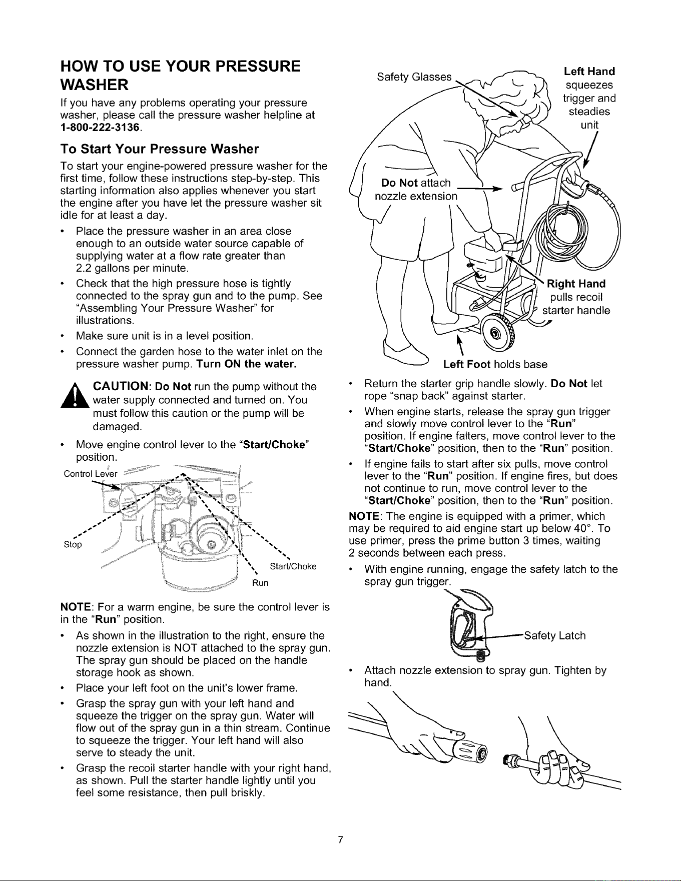
• Move engine control lever to the "Start/Choke"
position.
Control Lever :'_::_:_;_:"_..........
NOTE: For a warm engine, be sure the control lever is
in the "Run" position.
• As shown in the illustration to the right, ensure the
nozzle extension is NOT attached to the spray gun.
The spray gun should be placed on the handle
storage hook as shown.
• Place your left foot on the unit's lower frame.
• Grasp the spray gun with your left hand and
squeeze the trigger on the spray gun. Water will
flow out of the spray gun in a thin stream. Continue
to squeeze the trigger. Your left hand will also
serve to steady the unit.
• Grasp the recoil starter handle with your right hand,
as shown. Pull the starter handle lightly until you
feel some resistance, then pull briskly.
Safety Glasses
Left Hand
squeezes
trigger and
steadies
unit
Right Hand
pulls recoil
starter handle
Left Foot holds base
• Return the starter grip handle slowly. Do Not let
rope "snap back" against starter.
• When engine starts, release the spray gun trigger
and slowly move control lever to the "Run"
position. If engine falters, move control lever to the
"Start/Choke" position, then to the "Run" position.
• If engine fails to start after six pulls, move control
lever to the "Run" position. If engine fires, but does
not continue to run, move control lever to the
"Start/Choke" position, then to the "Run" position.
NOTE: The engine is equipped with a primer, which
may be required to aid engine start up below 40 °. To
use primer, press the prime button 3 times, waiting
2 seconds between each press.
• With engine running, engage the safety latch to the
spray gun trigger.
Latch
• Attach nozzle extension to spray gun. Tighten by
hand.

How to Stop Your Pressure Washer
• Move control lever to "Stop" position.
• Squeeze trigger on the spray gun to relieve
pressure in the hose.
NOTE: A small amount of water will squirt out when
you release the pressure.
How To Use the Adjustable Nozzle
You now should know how to START your pressure
washer and how to STOP it. The information in this
section will tell you how to adjust the spray pattern
and apply detergent or other cleaning chemicals.
_ DANGER! Never adjust spray pattern when
spraying. Never put hands in front of nozzle to
adjust spray pattern.
Your spray gun is equipped with an adjustable nozzle
that permits you to change the spray pressure and the
spray pattern, as follows:
• Pushing the nozzle forward changes the spray
pressure from high to low pressure. Pulling the
nozzle back changes the pressure from low to high.
Slide nozzle backward for
high pressure mode.
Slide nozzle forward for
low pressure mode and
detergent application.
Twist nozzle counter-
clockwise for fan pattern.
Twisting the nozzle adjusts the spray pattern from
a narrow pattern to a fan pattern.
Twist nozzle clockwise for
narrow spray pattern.
Point the nozzle toward the ground, disengage the
safety latch, and press the trigger to test the
pattern.
vv
• For most effective cleaning, keep the spray nozzle
between 8 to 24 inches away from cleaning
surface.
• If you get the spray nozzle too close, especially
using high pressure mode, you may damage the
surface being cleaned.
• Do Not get closer than 8 inches when cleaning
tires.
Applying Detergent with the Adjustable
Nozzle
IMPORTANT: Use chemicals designed specifically for
pressure washers. Household detergents could
damage the pump.
IMPORTANT: You must attach all hoses before you
start the engine. Starting the engine without all the
hoses connected and without the water turned ON will
damage the pump.
To apply detergent, follow these steps:
• Review the use of the adjustable nozzle.
• Prepare detergent solution as required by the job.
• Hang the detergent solution container on the hook
attached to the handle.
• Place the filter end of the detergent siphoning tube
into the detergent container.
_ AUTION! When inserting the filter into the
detergent container, route the tube so as to
keep it from inadvertently contacting the hot
muffler.
• Make sure the garden hose is connected to the
water inlet. Check that the high pressure hose is
connected to the spray gun and the pump. Start
the engine.
• Attach the nozzle extension to the spray gun. Slide
the adjustable nozzle forward to low pressure
mode. Detergent cannot be applied with the nozzle
in high pressure position.
• Apply detergent to a dry surface, starting from the
bottom and working up.
• Allow the detergent to "soak in" for 3-5 minutes
before rinsing. Reapply as needed to prevent
surface from drying.
• Start at lower portion of area to be washed and
work upward, using even overlapping strokes.
IMPORTANT: You must flush the chemical injection
system after each use by placing the filter into a clean
bucket of water and running the pressure washer in
low pressure for 1-2 minutes.
Pressure Washer Rinsing
WARNING! Be extremely careful if you use the
pressure washer from a ladder, scaffolding or
any other relatively unstable location. Pressure
in a running washer builds as you climb. When
you press the trigger, the recoil from the initial
spray could cause you to fall. The high pressure
spray could also cause you to fall if you are too
close to the cleaning surface.
For Rinsing:
• Slide the nozzle backward to high pressure, press
the trigger and wait for the detergent to clear.
NOTE: You can also stop detergent flow by removing
detergent siphoning tube from container.
• Keep the spray gun a safe distance from the area
you plan to spray.
• Apply a high pressure spray to a small area, then
check the surface for damage. If no damage is
found, it is okay to continue cleaning.
• Start at the top of the area to be rinsed, working
down with same overlapping strokes as you used
for washing and applying detergent.
Automatic Cool Down System
(Thermal Relief)
Ifyou run the engineon your pressure washer for
3-5 minutes withoutpressing the triggeron the spray gun,
circulating water in the pump can reach temperatures
between 140-145°F. The automatic cool down system
cools the pump by discharging the warm water onto the
ground, preventing internal pump damage.
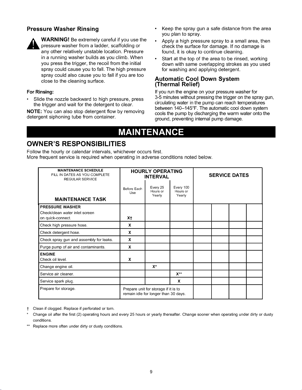
OWNER'S RESPONSIBILITIES
Follow the hourly or calendar intervals, whichever occurs first.
More frequent service is required when operating in adverse conditions noted below.
MAINTENANCE SCHEDULE
FILLIN DATES AS YOU COMPLETE
REGULAR SERVICE
MAINTENANCE TASK
PRESSURE WASHER
Check/clean water inlet screen
on quick-connect.
Check high pressure hose.
Check detergent hose.
Check spray gun and assembly for leaks.
Purge pump of air and contaminants.
ENGINE
Check oil level.
Change engine oil.
Service air cleaner.
Service spark plug.
Prepare for storage.
HOURLY OPERATING
INTERVAL
Before Each Every 25
Use Hours or
Yearly
xt
X
X
X
X
X
X*
X**
X
Prepare unit for storage if it is to
remain idle for longer than 30 days.
Every 100
Hours or
Yearly
SERVICE DATES
1 Clean if clogged. Replace if perforated or torn.
* Change oil after the first (2) operating hours and every 25 hours or yearly thereafter. Change sooner when operating under dirty or dusty
conditions.
** Replace more often under dirty or dusty conditions.
PRODUCT SPECIFICATIONS
Pressure Washer Specifications
Pressure ................... 2,000 PSI
Flow Rate .................. 2.0 GPM
Chemical Mix ............... Use as directed
Water Supply Temperature ..... Not to Exceed 140°F
Engine Specifications
Rated Horsepower ........... 5.5 HP
Spark Plug
Type: ................ Champion RJ-19LM
Set Gap To: ........... 0.030inch (0.76mm)
Gasoline Capacity ............ 1.5 Quarts
Oil
General Purpose ...... SAE 30
GENERAL RECOMMENDATIONS
The pressure washers warranty does not cover items
that have been subjected to operator abuse or
negligence. To receive full value from the warranty,
the operator must maintain pressure washer as
instructed in this manual.
Some adjustments will need to be made periodically to
properly maintain your pressure washer.
All service and adjustments should be made at least
once each season. Follow the requirements in the
"Maintenance Schedule" chart above.
NOTE: Once a year you should clean or replace the
spark plug and replace the air filter. A new spark plug
and clean air filter assure proper fuel-air mixture and
help your engine run better and last longer.
BEFORE EACH USE
• Check engine oil level.
• Check water inlet screen for damage.
• Check in-line filter for damage.
• Check high pressure hose for leaks.
• Check chemical filters for damage.
• Check spray gun and nozzle extension assembly
for leaks.
• Purge pump of air and contaminants.
PRESSURE WASHER
MAINTENANCE
Check and Clean Inlet Screen
Examine garden hose inlet screen. Clean if it is
clogged or replace ifit is torn.
Check High Pressure Hose
High pressure hoses can develop leaks from wear,
kinking, or abuse. Inspect hose before each use.
Check for cuts, leaks, abrasions, bulging of cover, or
damage or movement of couplings. If any of these
conditions exist, replace hose immediately.
_ ANGER! Never repair a high pressure hose.
Replace with hose that exceeds the maximum
pressure rating of your pressure washer.
Check Spray Gun and Nozzle Extension
Examine hose connection to spray gun and make sure
it is secure. Test trigger by pressing it and making
sure it springs back into place when you release it.
Engage safety latch and test trigger. You should not
be able to press trigger. Replace spray gun
immediately if it fails any of these tests.
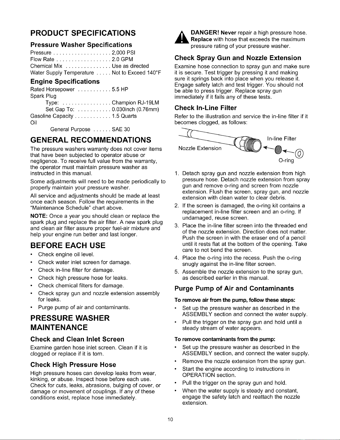
Check In-Line Filter
Refer to the illustration and service the in-line filter if it
becomes clogged, as follows:
Nozzle Extension
In-line Filter
O-ring
1. Detach spray gun and nozzle extension from high
pressure hose. Detach nozzle extension from spray
gun and remove o-ring and screen from nozzle
extension. Flush the screen, spray gun, and nozzle
extension with clean water to clear debris.
2. If the screen is damaged, the o-ring kit contains a
replacement in-line filter screen and an o-ring. If
undamaged, reuse screen.
3. Place the in-line filter screen into the threaded end
of the nozzle extension. Direction does not matter.
Push the screen in with the eraser end of a pencil
until it rests flat at the bottom of the opening. Take
care to not bend the screen.
4. Place the o-ring into the recess. Push the o-ring
snugly against the in-line filter screen.
5. Assemble the nozzle extension to the spray gun,
as described earlier in this manual.
Purge Pump of Air and Contaminants
To remove air from the pump, follow these steps:
• Set up the pressure washer as described in the
ASSEMBLY section and connect the water supply.
• Pull the trigger on the spray gun and hold until a
steady stream of water appears.
To remove contaminants from the pump:
• Set up the pressure washer as described in the
ASSEMBLY section, and connect the water supply.
• Remove the nozzle extension from the spray gun.
• Start the engine according to instructions in
OPERATION section.
• Pull the trigger on the spray gun and hold.
• When the water supply is steady and constant,
engage the safety latch and reattach the nozzle
extension.
10
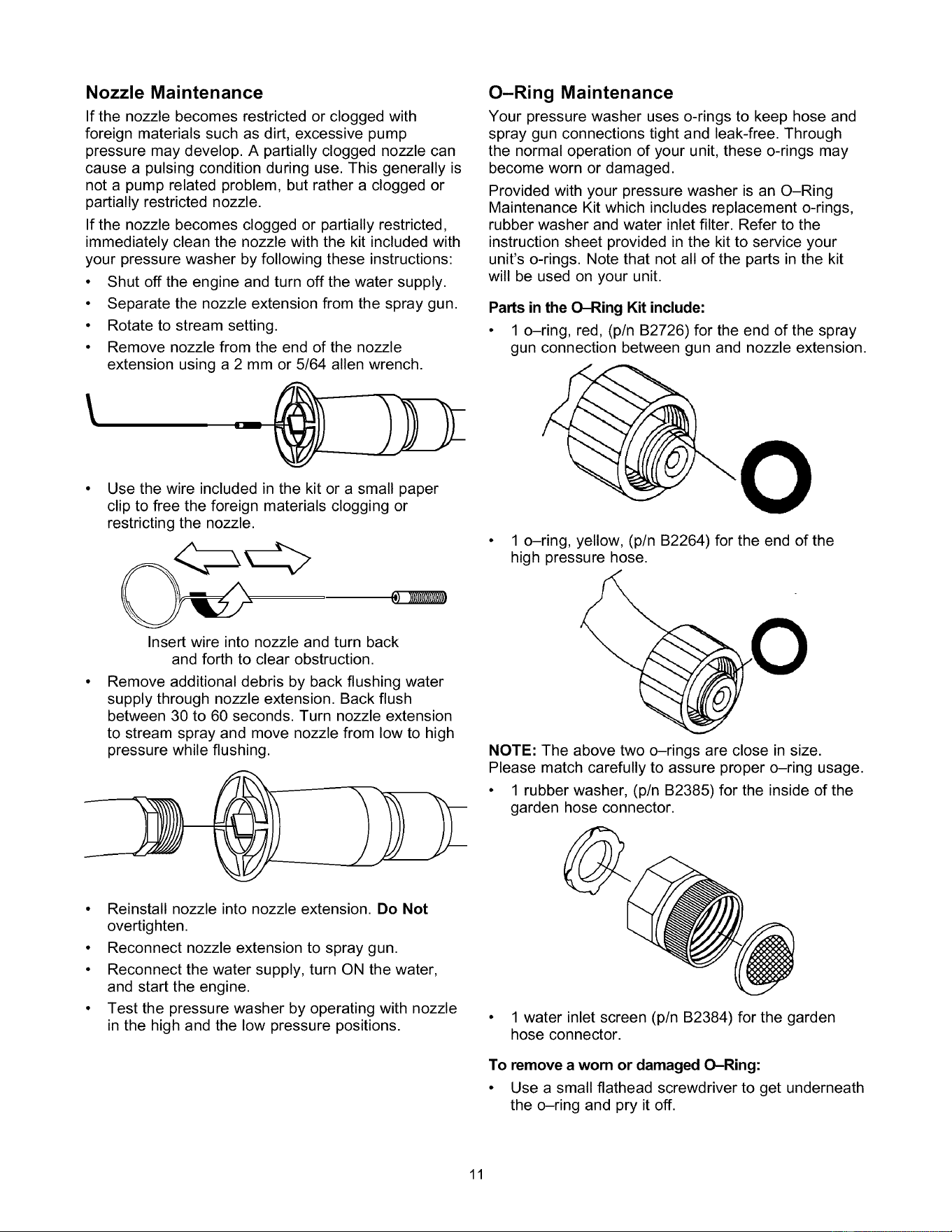
Nozzle Maintenance
If the nozzle becomes restricted or clogged with
foreign materials such as dirt, excessive pump
pressure may develop. A partially clogged nozzle can
cause a pulsing condition during use. This generally is
not a pump related problem, but rather a clogged or
partially restricted nozzle.
If the nozzle becomes clogged or partially restricted,
immediately clean the nozzle with the kit included with
your pressure washer by following these instructions:
• Shut off the engine and turn off the water supply.
• Separate the nozzle extension from the spray gun.
• Rotate to stream setting.
• Remove nozzle from the end of the nozzle
extension using a 2 mm or 5/64 allen wrench.
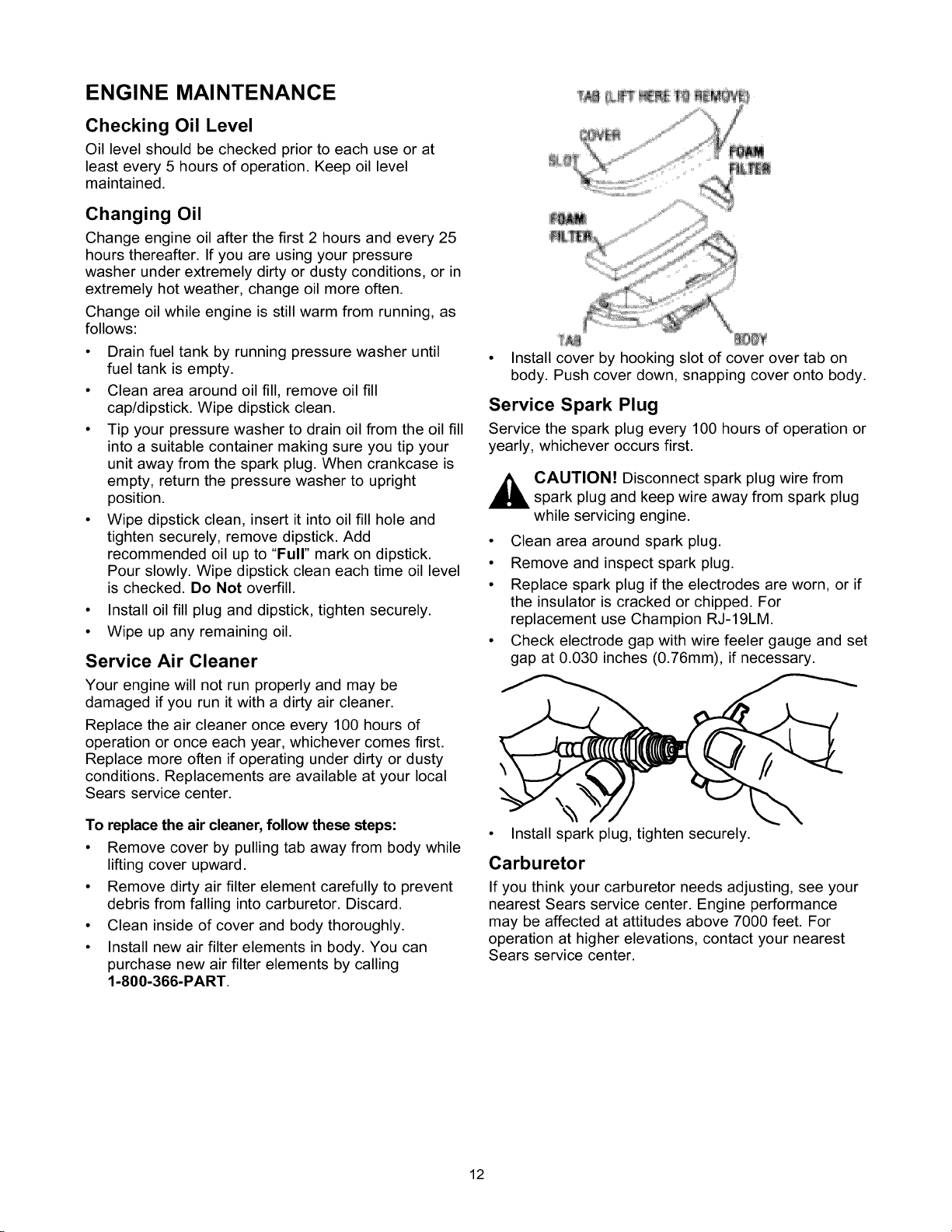
O-Ring Maintenance
Your pressure washer uses o-rings to keep hose and
spray gun connections tight and leak-free. Through
the normal operation of your unit, these o-rings may
become worn or damaged.
Provided with your pressure washer is an O-Ring
Maintenance Kit which includes replacement o-rings,
rubber washer and water inlet filter. Refer to the
instruction sheet provided in the kit to service your
unit's o-rings. Note that not all of the parts in the kit
will be used on your unit.
Parts in the O-Ring Kit include:
• 1 o-ring, red, (p/n B2726) for the end of the spray
gun connection between gun and nozzle extension.
Use the wire included in the kit or a small paper
clip to free the foreign materials clogging or
restricting the nozzle.
O
1 o-ring, yellow, (p/n B2264) for the end of the
high pressure hose.
Insert wire into nozzle and turn back
and forth to clear obstruction.
Remove additional debris by back flushing water
supply through nozzle extension. Back flush
between 30 to 60 seconds. Turn nozzle extension
to stream spray and move nozzle from low to high
pressure while flushing. NOTE: The above two o-rings are close in size.
Please match carefully to assure proper o-ring usage.
• 1 rubber washer, (p/n B2385) for the inside of the
garden hose connector.
• Reinstall nozzle into nozzle extension. Do Not
overtighten.
• Reconnect nozzle extension to spray gun.
• Reconnect the water supply, turn ON the water,
and start the engine.
• Test the pressure washer by operating with nozzle
in the high and the low pressure positions.
• 1 water inlet screen (p/n B2384) for the garden
hose connector.
To remove a worn or damaged O-Ring:
• Use a small flathead screwdriver to get underneath
the o-ring and pry it off.
11
ENGINE MAINTENANCE
Checking Oil Level
Oil level should be checked prior to each use or at
least every 5 hours of operation. Keep oil level
maintained.
Changing Oil
Change engine oil after the first 2 hours and every 25
hours thereafter. If you are using your pressure
washer under extremely dirty or dusty conditions, or in
extremely hot weather, change oil more often.
Change oil while engine is still warm from running, as
follows:
• Drain fuel tank by running pressure washer until
fuel tank is empty.
• Clean area around oil fill, remove oil fill
cap/dipstick. Wipe dipstick clean.
• Tip your pressure washer to drain oil from the oil fill
into a suitable container making sure you tip your
unit away from the spark plug. When crankcase is
empty, return the pressure washer to upright
position.
• Wipe dipstick clean, insert it into oil fill hole and
tighten securely, remove dipstick. Add
recommended oil up to "Full" mark on dipstick.
Pour slowly. Wipe dipstick clean each time oil level
is checked. Do Not overfill.
• Install oil fill plug and dipstick, tighten securely.
• Wipe up any remaining oil.
Service Air Cleaner
Your engine will not run properly and may be
damaged if you run it with a dirty air cleaner.
Replace the air cleaner once every 100 hours of
operation or once each year, whichever comes first.
Replace more often if operating under dirty or dusty
conditions. Replacements are available at your local
Sears service center.
To replace the air cleaner, follow these steps:
• Remove cover by pulling tab away from body while
lifting cover upward.
• Remove dirty air filter element carefully to prevent
debris from falling into carburetor. Discard.
• Clean inside of cover and body thoroughly.
• Install new air filter elements in body. You can
purchase new air filter elements by calling
1-800-366-PART.
• Install cover by hooking slot of cover over tab on
body. Push cover down, snapping cover onto body.
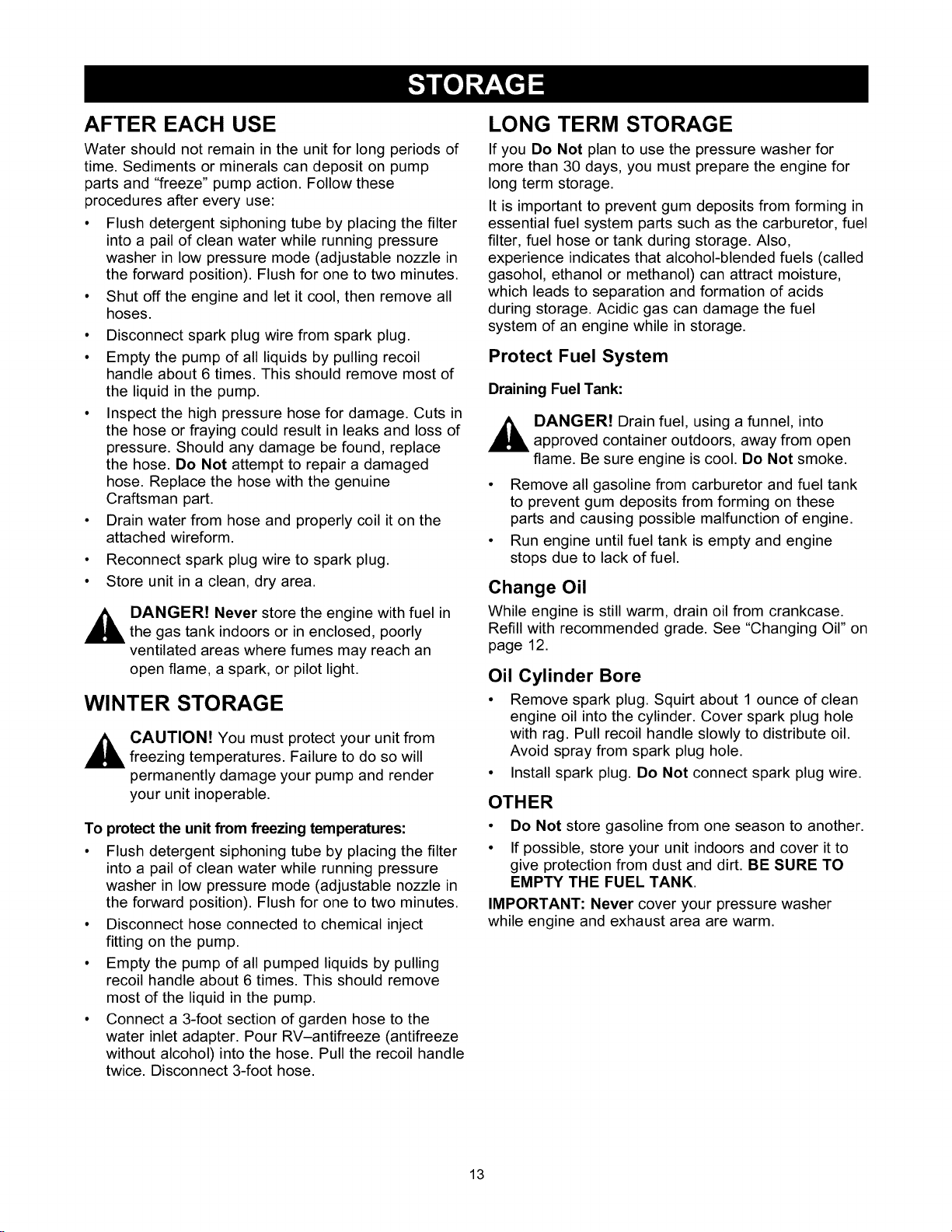
Service Spark Plug
Service the spark plug every 100 hours of operation or
yearly, whichever occurs first.
_ CAUTION! Disconnect spark plug wire from
spark plug and keep wire away from spark plug
while servicing engine.
• Clean area around spark plug.
• Remove and inspect spark plug.
• Replace spark plug if the electrodes are worn, or if
the insulator is cracked or chipped. For
replacement use Champion RJ-19LM.
• Check electrode gap with wire feeler gauge and set
gap at 0.030 inches (0.76mm), if necessary.
• Install spark plug, tighten securely.
Carburetor
If you think your carburetor needs adjusting, see your
nearest Sears service center. Engine performance
may be affected at attitudes above 7000 feet. For
operation at higher elevations, contact your nearest
Sears service center.
12
AFTER EACH USE
Water should not remain in the unit for long periods of
time. Sediments or minerals can deposit on pump
parts and "freeze" pump action. Follow these
procedures after every use:
• Flush detergent siphoning tube by placing the filter
into a pail of clean water while running pressure
washer in low pressure mode (adjustable nozzle in
the forward position). Flush for one to two minutes.
• Shut off the engine and let it cool, then remove all
hoses.
• Disconnect spark plug wire from spark plug.
• Empty the pump of all liquids by pulling recoil
handle about 6 times. This should remove most of
the liquid in the pump.
• Inspect the high pressure hose for damage. Cuts in
the hose or fraying could result in leaks and loss of
pressure. Should any damage be found, replace
the hose. Do Not attempt to repair a damaged
hose. Replace the hose with the genuine
Craftsman part.
• Drain water from hose and properly coil it on the
attached wireform.
• Reconnect spark plug wire to spark plug.
• Store unit in a clean, dry area.
_ ANGER! Never store the engine with fuel in
the gas tank indoors or in enclosed, poorly
ventilated areas where fumes may reach an
open flame, a spark, or pilot light.
WINTER STORAGE
_ AUTION! You must protect your unit from
freezing temperatures. Failure to do so will
permanently damage your pump and render
your unit inoperable.
To protect the unit from freezing temperatures:
• Flush detergent siphoning tube by placing the filter
into a pail of clean water while running pressure
washer in low pressure mode (adjustable nozzle in
the forward position). Flush for one to two minutes.
• Disconnect hose connected to chemical inject
fitting on the pump.
• Empty the pump of all pumped liquids by pulling
recoil handle about 6 times. This should remove
most of the liquid in the pump.
• Connect a 3-foot section of garden hose to the
water inlet adapter. Pour RV-antifreeze (antifreeze
without alcohol) into the hose. Pull the recoil handle
twice. Disconnect 3-foot hose.
LONG TERM STORAGE
If you Do Not plan to use the pressure washer for
more than 30 days, you must prepare the engine for
long term storage.
It is important to prevent gum deposits from forming in
essential fuel system parts such as the carburetor, fuel
filter, fuel hose or tank during storage. Also,
experience indicates that alcohol-blended fuels (called
gasohol, ethanol or methanol) can attract moisture,
which leads to separation and formation of acids
during storage. Acidic gas can damage the fuel
system of an engine while in storage.
Protect Fuel System
Draining Fuel Tank:
_ ANGER! Drain fuel, using a funnel, into
approved container outdoors, away from open
flame. Be sure engine is cool. Do Not smoke.
• Remove all gasoline from carburetor and fuel tank
to prevent gum deposits from forming on these
parts and causing possible malfunction of engine.
• Run engine until fuel tank is empty and engine
stops due to lack of fuel.
Change Oil
While engine is still warm, drain oil from crankcase.
Refill with recommended grade. See "Changing Oil" on
page 12.
Oil Cylinder Bore
• Remove spark plug. Squirt about 1 ounce of clean
engine oil into the cylinder. Cover spark plug hole
with rag. Pull recoil handle slowly to distribute oil.
Avoid spray from spark plug hole.
• Install spark plug. Do Not connect spark plug wire.
OTHER
• Do Not store gasoline from one season to another.
• If possible, store your unit indoors and cover it to
give protection from dust and dirt. BE SURE TO
EMPTY THE FUEL TANK.
IMPORTANT: Never cover your pressure washer
while engine and exhaust area are warm.
13
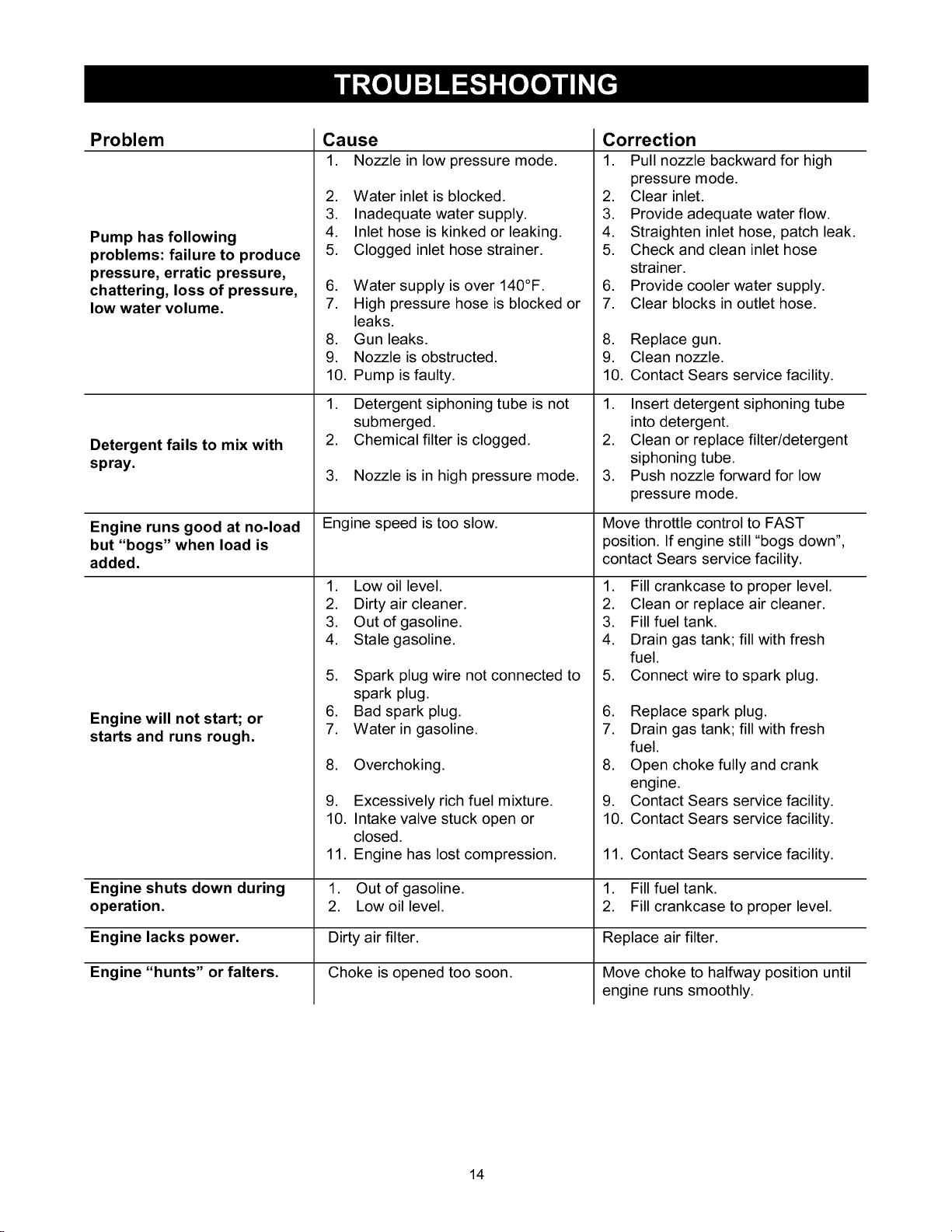
Problem Cause Correction
1. Nozzle in low pressure mode. 1. Pull nozzle backward for high
Pump has following
problems: failure to produce
pressure, erratic pressure,
chattering, loss of pressure,
low water volume.
Detergent fails to mix with
spray.
Engine runs good at no-load
but "bogs" when load is
added.
Engine will not start; or
starts and runs rough.
2. Water inlet is blocked.
3. Inadequate water supply.
4. Inlet hose is kinked or leaking.
5. Clogged inlet hose strainer.
6. Water supply is over 140°F.
7. High pressure hose is blocked or
leaks.
8. Gun leaks.
9. Nozzle is obstructed.
10. Pump is faulty.
1. Detergent siphoning tube is not
submerged.
2. Chemical filter is clogged.
3. Nozzle is in high pressure mode.
Engine speed is too slow.
1. Low oil level.
2. Dirty air cleaner.
3. Out of gasoline.
4. Stale gasoline.
5. Spark plug wire not connected to
pressure mode.
2. Clear inlet.
3. Provide adequate water flow.
4. Straighten inlet hose, patch leak.
5. Check and clean inlet hose
strainer.
6. Provide cooler water supply.
7. Clear blocks in outlet hose.
8. Replace gun.
9. Clean nozzle.
10. Contact Sears service facility.
1. Insert detergent siphoning tube
into detergent.
2. Clean or replace filter/detergent
siphoning tube.
3. Push nozzle forward for low
pressure mode.
Move throttle control to FAST
position. If engine still "bogs down",
contact Sears service facility.
1. Fill crankcase to proper level.
2. Clean or replace air cleaner.
3. Fill fuel tank.
4. Drain gas tank; fill with fresh
fuel.
5. Connect wire to spark plug.
spark plug.
6. Bad spark plug.
7. Water in gasoline.
8. Overchoking.
6. Replace spark plug.
7. Drain gas tank; fill with fresh
fuel.
8. Open choke fully and crank
engine.
9. Excessively rich fuel mixture.
10. Intake valve stuck open or
closed.
11. Engine has lost compression.
9. Contact Sears service facility.
10. Contact Sears service facility.
11. Contact Sears service facility.
Engine shuts down during 1. Out of gasoline. 1. Fill fuel tank.
operation. 2. Low oil level. 2. Fill crankcase to proper level.
Engine lacks power. Dirty air filter.
Engine "hunts" or falters. Choke is opened too soon.
Replace air filter.
Move choke to halfway position until
engine runs smoothly.
14
15

CRAFTSMAN 2000 PSI Pressure Washer 580.768210
Main Unit m Exploded View
\\\\\\
26_
51
45
28
7
4
_9
10
41
29_
\\\\\
52
900_
16
34_
__ _24
58 23 _ _
40 39
16
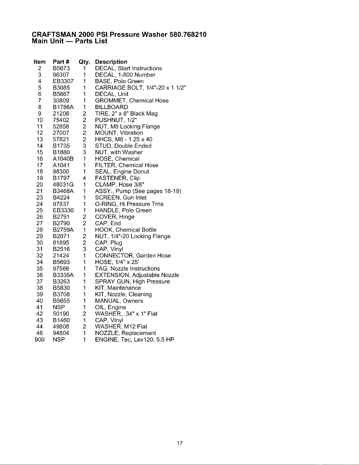
CRAFTSMAN 2000 PSI Pressure Washer 580.768210
Main Unit m Parts List
Item PaN #
2 B5673
3 96307
4 EB3307
5 B3085
6 B5667
7 30809
8 B1786A
9 21206
10 75402
11 52858
12 27007
13 57821
14 B1735
15 B1880
16 A1040B
17 A1041
18 98300
19 B1797
20 48031G
21 B3468A
23 B4224
24 97837
25 EB3330
26 B2791
27 B2790
28 B2759A
29 B2071
30 81895
31 B2516
32 21424
34 B5693
35 97566
36 B3335A
37 B3263
38 B5830
39 B3708
40 B5655
41 NSP
42 50190
43 B1460
44 49808
46 94804
900 NSP
Qty. Description
1 DECAL, Start Instructions
1 DECAL, 1-800 Number
1 BASE, Polo Green
1 CARRIAGE BOLT, 1/4"-20 x 1 1/2"
1 DECAL, Unit
1 GROMMET, Chemical Hose
1 BILLBOARD
2 TIRE, 2"x 8" Black Mag
2 PUSHNUT, 1/2"
2 NUT, M8 Locking Flange
2 MOUNT, Vibration
2 HHCS, M8- 1.25 x40
3 STUD, Double Ended
3 NUT, with Washer
1 HOSE, Chemical
1 FILTER, Chemical Hose
1 SEAL, Engine Donut
4 FASTENER, Clip
1 CLAMP, Hose 3/8"
1 ASSY., Pump (See pages 18-19)
1 SCREEN, Gun Inlet
1 O-RING, Hi Pressure Trns
1 HANDLE, Polo Green
2 COVER, Hinge
2 CAP, End
1 HOOK, Chemical Bottle
2 NUT, 1/4"-20 Locking Flange
2 CAP, Plug
3 CAP, Vinyl
1 CONNECTOR, Garden Hose
1 HOSE, 1/4" x 25'
1 TAG, Nozzle Instructions
1 EXTENSION, Adjustable Nozzle
1 SPRAY GUN, High Pressure
1 KIT, Maintenance
1 KIT, Nozzle, Cleaning
1 MANUAL, Owners
1 OIL, Engine
2 WASHER, .34" x 1" Flat
1 CAP, Vinyl
2 WASHER, M12 Flat
1 NOZZLE, Replacement
1 ENGINE, Tec, Lev120, 5.5 HP
17

CRAFTSMAN 2000 PSI Pressure Washer 580.768210
Pump m Exploded View
--161
3
12
2l 29 2_
24
43 42
2
1_0 / .3
%j6
9 L7___--_23
_-----8
30_ 33 34
36
30
37
37
/
39 40
11-'-
37 __5.._--
32
18

CRAFTSMAN 2000 PSI Pressure Washer 580.768210
Pump m Parts List
Item PaN #
1 98300
2 97962
3 96795
4 21429
5 97835
6 21783
7 93680
8 97831
9 B2702
10 98227
11 B2310
......
......
5 ......
12 ......
13 ......
14 ......
15 ......
16 ......
17 185287
18 ......
19 ......
20 ......
21 ......
22 ......
28 ......
23 185711
21 ......
24 ......
25 ......
26 ......
27 ......
29 ......
46 ......
30 B3513
31 ......
32 ......
37 ......
Qty. Description Item Part #
1 SEAL, Engine Donut 33 B3286
3 SHCS, M6 - 1 x 25 34 97837
3 SLEEVE, Grommet Spacer
6 BUSHING, Rubber Mount 35 97841
1 O-RING, Housing Seal 36 97840
1 THERMAL RELIEF, GPW-EG 37 40946
3 SEAL, Oil Piston 15 TC4 38 B4186
3 SPACER, Pilot 37 ......
1 HOUSING, Piston 39 ......
1 ADAPTER, Engine 40 ......
0 KIT, AXIAL CAM SERV 41 B2312
1 SEAL, Engine Donut 1 ......
3 SHCS, M6- 1 x 25 2 ......
1 O-RING, Housing Seal 5 ......
1 WASHER, Brg. 36 x 65 x 6Thk 42 ......
1 ASSY., Brg. Cage 45 x 65 43 ......
1 WASHER, Brg. 45 x 65 x 1 44 ......
1 CAM, Axial 5.6 VS 45 B1933
1 BALL BEARING, 35 x 72 x 17 1 ......
0 KIT, CHEM INJECT 2 ......
1 FITTING, Chem Inject 5 ......
1 BALL, Chem Inject 7 ......
1 SPRING, Chem Inject 21 ......
1 O-RING, Venturi & Seat, Black 25 ......
1 VENTURI, Chem Inject 28 ......
1 O-RING, Venturi, Yellow 31 ......
0 KIT, UNLOADER 33 ......
1 O-RING, Venturi & Seat, Black 34 ......
1 CAP, Unloader
1 O-RING, Unloader Cap 36 ......
1 SPRING, 2000 Unloader 37 ......
1 PISTON, Unloader
1 SEAT, 2000 Unloader
1 WASHER, 1.5mm Shim
0 KIT, CHECK VALVES
6 O-RING, Check Valve
6 ASSY., Check Valve
4 SHCS, M6-1.0 x 35
Qty. Description
3 SEAL, Double-Lip
1 O-RING, Hi-Pressure
Transfer
3 CAP, Outlet Check Valve
3 O-RING, Outlet CV Cap
4 SHCS, M6-1.0 x 35
0 KIT, HEAD CASTING SFG
4 SHCS, M6-1.0 x 35
1 HEAD, Pump
1 PLUG, 1/8-28 W/VIBR
0 KIT, PISTON & SPRING
1 SEAL, Engine Donut
3 SHCS, M6- 1 x 25
1 O-RING, Housing Seal
3 RETAINER, Piston Spring
3 PISTON, Dia. 15 x 65
3 SPRING, Piston Return
0 KIT, O-RING/SEAL SERV
1 SEAL, Engine Donut
3 SHCS, M6- 1 x 25
1 O-RING, Housing Seal
3 SEAL, Oil Piston 15 TC4
2 O-RING, Venturi & Seat, Black
1 O-RING, Unloader Cap
1 O-RING, Venturi, Yellow
6 O-RING, Check Valve
3 SEAL, Double-Lip
1 O-RING, High Pressure
Transfer
3 O-RING, Outlet CV Cap
4 SHCS, M6-1.0 x 35
Item numbers 11, 17, 23, 30, 38, 41, and 45 are
service kits and include all parts shown within the box.
Certain parts may only be available as components of
a kit.
19
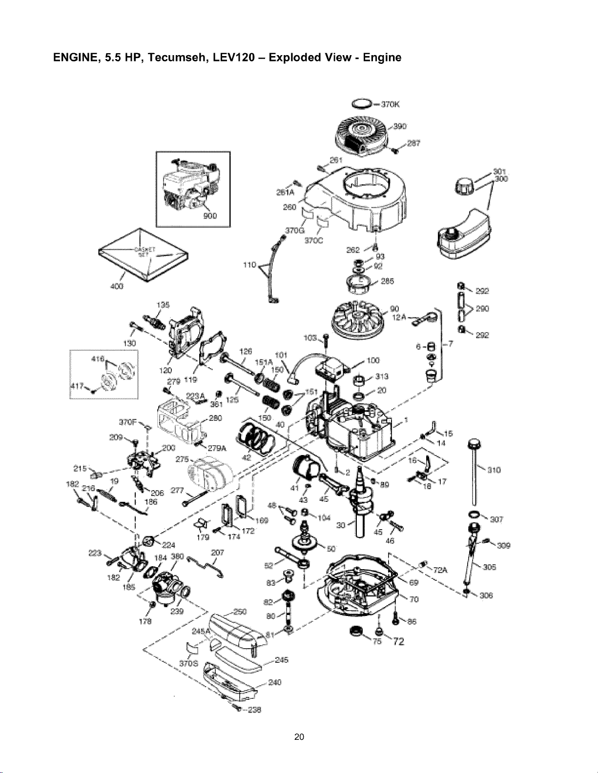
ENGINE, 5.5 HP, Tecumseh, LEV120 - Exploded View - Engine
4_
i:2
2g?
4i
20
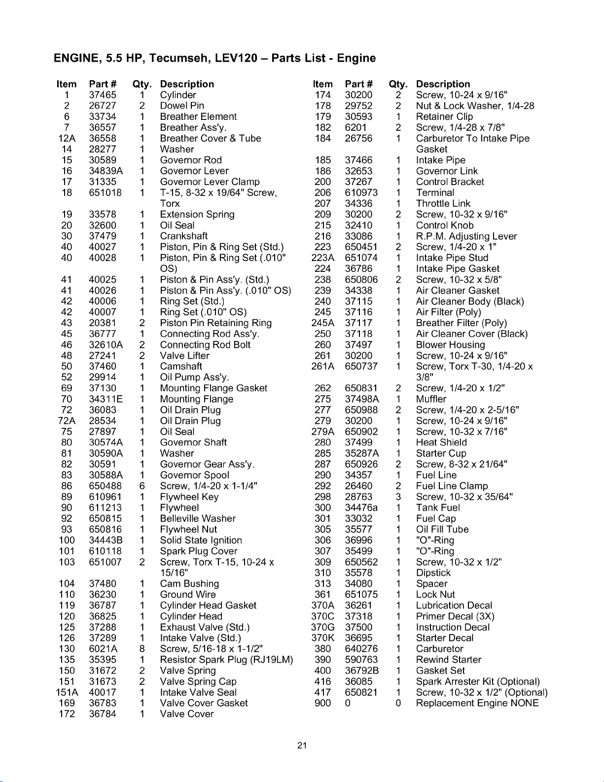
ENGINE, 5.5 HP, Tecumseh, LEV120 - Parts List - Engine
Item PaN #
1 37465
2 26727
6 33734
7 36557
12A 36558
14 28277
15 30589
16 34839A
17 31335
18 651018
19 33578
20 32600
30 37479
40 40027
40 40028
41 40025
41 40026
42 40006
42 40007
43 20381
45 36777
46 32610A
48 27241
50 37460
52 29914
69 37130
70 34311E
72 36083
72A 28534
75 27897
80 30574A
81 30590A
82 30591
83 30588A
86 650488
89 610961
90 611213
92 650815
93 650816
100 34443B
101 610118
103 651007
104 37480
110 36230
119 36787
120 36825
125 37288
126 37289
130 6021A
135 35395
150 31672
151 31673
151A 40017
169 36783
172 36784
Qty. Description Item Part #
1 Cylinder 174 30200
2 Dowel Pin 178 29752
1 Breather Element 179 30593
1 Breather Ass'y. 182 6201
1 Breather Cover & Tube 184 26756
1 Washer
1 Governor Rod 185 37466
1 Governor Lever 186 32653
1 Governor Lever Clamp 200 37267
1 T-15, 8-32 x 19/64" Screw, 206 610973
Torx 207 34336
1 Extension Spring 209 30200
1 Oil Seal 215 32410
1 Crankshaft 216 33086
1 Piston, Pin & Ring Set (Std.) 223 650451
1 Piston, Pin & Ring Set (.010" 223A 651074
OS) 224 36786
1 Piston & Pin Ass'y. (Std.) 238 650806
1 Piston & Pin Ass'y. (.010" OS) 239 34338
1 Ring Set (Std .) 240 37115
1 Ring Set (.010" OS) 245 37116
2 Piston Pin Retaining Ring 245A 37117
1 Connecting Rod Ass'y. 250 37118
2 Connecting Rod Bolt 260 37497
2 Valve Lifter 261 30200
1 Camshaft 261A 650737
1 Oil Pump Ass'y.
1 Mounting Flange Gasket 262 650831
1 Mounting Flange 275 37498A
1 Oil Drain Plug 277 650988
1 Oil Drain Plug 279 30200
1 Oil Seal 279A 650902
1 Governor Shaft 280 37499
1 Washer 285 35287A
1 Governor Gear Ass'y. 287 650926
1 Governor Spool 290 34357
6 Screw, 1/4-20 x 1-1/4" 292 26460
1 Flywheel Key 298 28763
1 Flywheel 300 34476a
1 Belleville Washer 301 33032
1 Flywheel Nut 305 35577
1 Solid State Ignition 306 36996
1 Spark Plug Cover 307 35499
2 Screw, Torx T-15, 10-24 x 309 650562
15/16" 310 35578
1 Cam Bushing 313 34080
1 Ground Wire 361 651075
1 Cylinder Head Gasket 370A 36261
1 Cylinder Head 370C 37318
1 Exhaust Valve (Std.) 370G 37500
1 Intake Valve (Std.) 370K 36695
8 Screw, 5/16-18 x 1-1/2" 380 640276
1 Resistor Spark Plug (RJ 19LM) 390 590763
2 Valve Spring 400 36792B
2 Valve Spring Cap 416 36085
1 Intake Valve Seal 417 650821
1 Valve Cover Gasket 900 0
1 Valve Cover
Qty. Description
2 Screw, 10-24 x 9/16"
2 Nut & Lock Washer, 1/4-28
1 Retainer Clip
2 Screw, 1/4-28 x 7/8"
1 Carburetor To Intake Pipe
Gasket
1 Intake Pipe
1 Governor Link
1 Control Bracket
1 Terminal
1 Throttle Link
2 Screw, 10-32 x 9/16"
1 Control Knob
1 R.P.M. Adjusting Lever
2 Screw, 1/4-20 x 1"
1 Intake Pipe Stud
1 Intake Pipe Gasket
2 Screw, 10-32 x 5/8"
1 Air Cleaner Gasket
1 Air Cleaner Body (Black)
1 Air Filter (Poly)
1 Breather Filter (Poly)
1 Air Cleaner Cover (Black)
1 Blower Housing
1 Screw, 10-24 x 9/16"
1 Screw, Torx T-30, 1/4-20 x
3/8"
2 Screw, 1/4-20 x 1/2"
1 Muffler
2 Screw, 1/4-20 x 2-5/16"
1 Screw, 10-24 x 9/16"
1 Screw, 10-32 x 7/16"
1 Heat Shield
1 Starter Cup
2 Screw, 8-32 x 21/64"
1 Fuel Line
2 Fuel Line Clamp
3 Screw, 10-32 x 35/64"
1 Tank Fuel
1 Fuel Cap
1 Oil Fill Tube
1 "O"-Ring
1 "O"-Ring
1 Screw, 10-32 x 1/2"
1 Dipstick
1 Spacer
1 Lock Nut
1 Lubrication Decal
1 Primer Decal (3X)
1 Instruction Decal
1 Starter Decal
1 Carburetor
1 Rewind Starter
1 Gasket Set
1 Spark Arrester Kit (Optional)
1 Screw, 10-32 x 1/2" (Optional)
0 Replacement Engine NONE
21

ENGINE, 5.5 HP, Tecumseh, LEV120 - Exploded View and Parts List - Recoil
--8
6
Item
0
1
2
3
4
5
Part # Qty. Description
590763 1 Rewind Starter
590599A 1 Spring Pin
590600 1 Washer
590696 1 Retainer
590601 1 Washer
590697 1 Brake Spring
Item
6
7
8
11
12
13
Part#
590698
590699
590700
590764
590535
590701
Qty. Description
2 Starter Dog
2 Dog Spring
1 Pulley & Rewind Spring Ass'y
1 Starter Housing Ass'y.
1 Starter Rope
1 Starter Handle
22
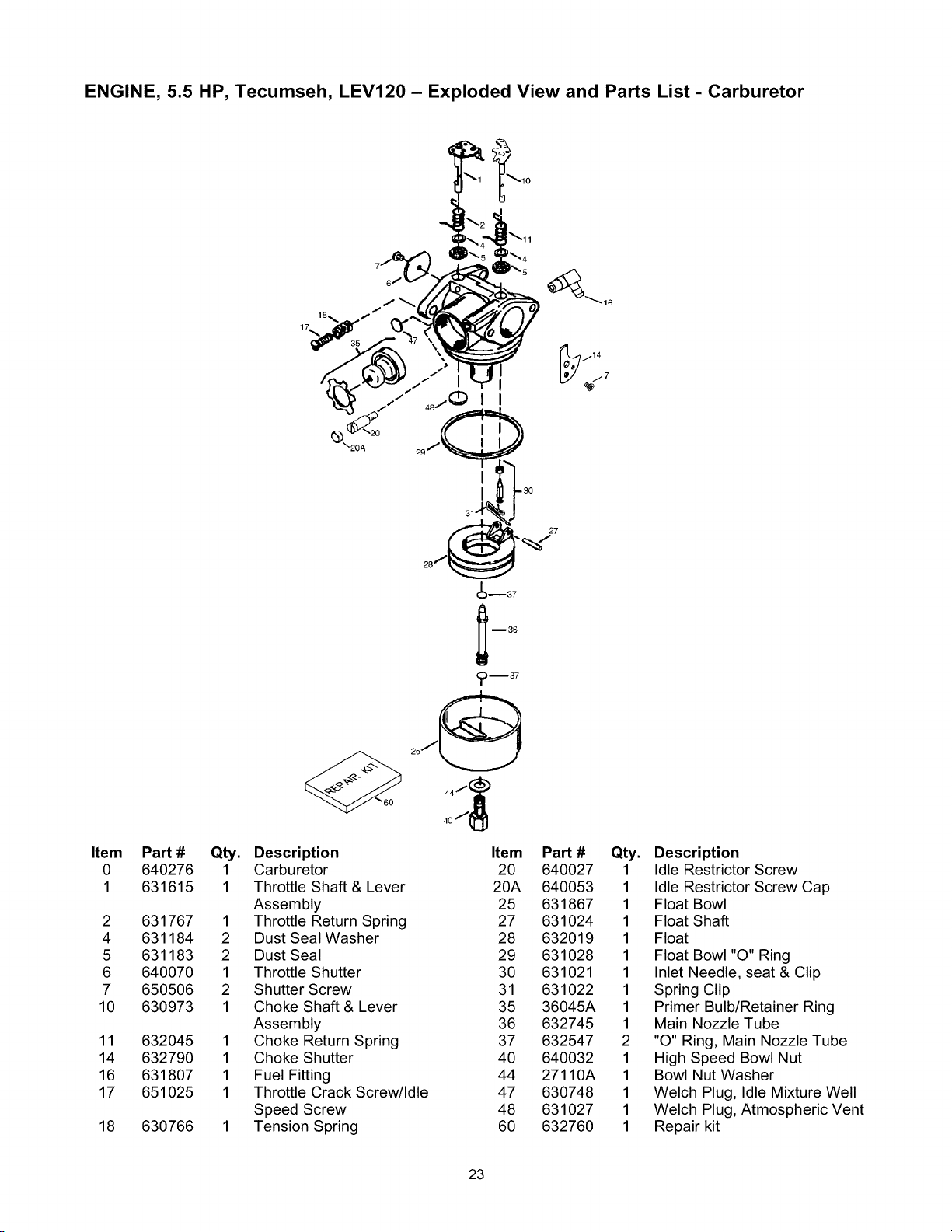
ENGINE, 5.5 HP, Tecumseh, LEV120 - Exploded View and Parts List - Carburetor
Item
0
1
2
4
5
6
7
10
11
14
16
17
18
Pan # Qty.
640276 1
631615 1
631767 1
631184 2
631183 2
640070 1
650506 2
630973 1
632045 1
632790 1
631807 1
651025 1
630766 1
f
(_\20A
60
Description
Carburetor
Throttle Shaft & Lever
Assembly
Throttle Return Spring
Dust Seal Washer
Dust Seal
Throttle Shutter
Shutter Screw
Choke Shaft & Lever
Assembly
Choke Return Spring
Choke Shutter
Fuel Fitting
Throttle Crack Screw/Idle
Speed Screw
Tension Spring
Item
20
20A
25
27
28
29
30
31
35
36
37
40
44
47
48
60
/14
j7
Pan # Qty.
640027 1
640053 1
631867 1
631024 1
632019 1
631028 1
631021 1
631022 1
36045A 1
632745 1
632547 2
640032 1
27110A 1
630748 1
631027 1
632760 1
Description
Idle Restrictor Screw
Idle Restrictor Screw Cap
Float Bowl
Float Shaft
Float
Float Bowl "O" Ring
Inlet Needle, seat & Clip
Spring Clip
Primer Bulb/Retainer Ring
Main Nozzle Tube
"O" Ring, Main Nozzle Tube
High Speed Bowl Nut
Bowl Nut Washer
Welch Plug, Idle Mixture Well
Welch Plug, Atmospheric Vent
Repair kit
23
Your Warranty Rights and Obligations
The California Air Resources Board ("CARB") and Sears
Roebuck and Co., USA, are pleased to explain the Emission
Control System Warranty on your model year 2000 and later
small off-road engine (engine). In California, new engines
must be designed, built and equipped to meet the State's
stringent anti-smog standards. Sears must warrant the
emission control system on your engine for the periods of
time listed below provided there has been no abuse, neglect,
or improper maintenance of your engine.
Your emission control system includes parts such as the
carburetor and the ignition system.
Where a warrantable condition exists, Sears will repair your
engine at no cost to you. Expenses covered under under
warranty include diagnosis, parts, and labor.
Manufacturer's Warranty Coverage
The model year 2000 and later engines are warranted for
two years. If any emission related part on your engine (as
listed below) is defective, the part will be repaired or
replaced by Sears.
Owner's Warranty Responsibilities
As the engine owner, you are responsible for the
performance of the required maintenance listed in this
owners manual. Sears recommends that you retain all
receipts covering maintenance on your engine, but Sears
cannot deny warranty solely due for the lack of receipts or
for your failure to ensure the performance of all scheduled
maintenance.
As the engine owner, you should be aware that Sears may
deny you warranty coverage if your engine or a part of it has
failed due to abuse, neglect, improper maintenance,
unapproved modifications, or the use of parts not made or
approved by the original equipment manufacturer.
You are responsible for presenting your engine to a Sears
authorized repair center as soon as a problem exists.
Warranty repairs should be completed in a reasonable
amount of time, not to exceed 30 days.
If you have any questions regarding your warranty rights and
responsibilities, you should contact your nearest authorized
service center or call Sears at 1-800-473-7247.
Warranty Commencement Date
The warranty period begins on the date the engine is
delivered.
Length of Coverage
Sears warrants to the initial owner and each subsequent
purchaser that the engine is free from defects in materials
and workmanship which cause the failure of a warranted
part for a period of two years.
WHAT IS COVERED
Repair or Replacement of Parts
• Repair or replacement of any warranted part will be
performed at no charge to the owner at an approved
Sears service center.
If you have any questions regarding your warranty rights
and responsibilities, your should contact your nearest
authorized service center or call Sears at
1-800-473-7247.
Warranty Period
Any warranted part which is not scheduled for replacement
as required maintenance, or which is scheduled only for
regular inspection to the effect of "repair or replace as
necessary" shall be warranted for 2 years. Any warranted
part which is scheduled for replacement as required
maintenance shall be warranted for the period of time up to
the first scheduled replacement point for that part.
Diagnosis
The owner shall not be charged for diagnostic labor which
leads to the determination that the warranted part is
defective if the diagnostic work is performed at an approved
Sears service center.
Consequential Damages
Sears may be liable for damages to other engine
components caused by the failure of a warranted part still
under warranty.
WHAT IS NOT COVERED
All failures caused by abuse, neglect, or improper
maintenance are not covered.
Add-on or Modified Parts
The use of add-on or modified parts can be grounds for
disallowing a warranty claim. Sears is not liable to cover
failures of warranted parts caused by the use of add-on or
modified parts.
How to File a Claim
If you have any questions regarding your warranty rights and
responsibilities, you should contact your nearest authorized
service center or call Sears at 1-800-473-7247.
Where to Get Warranty Service
Warranty services or repairs shall be provided at all Sears
authorized service centers.
Maintenance, Replacement and Repair of
Emission Related Parts
Any Sears approved replacement part used in the
performance of any warranty maintenance or repair on
emission related parts will be provided without charge to the
owner if the part it under warranty.
Emission Control Warranty Parts List
1. Carburetor Assembly
2. Ignition System
a. Spark Plug, covered up to maintenance schedule.
b. Ignition Module
3. Crankcase Breather Tube
4. Exhaust Manifold
24
GARANTIA................................... 25
INSTRUCCIONESDESEGURIDAD............. 25-26
MONTAJE................................. 27-28
OPERACION............................... 29-32
MANTENIMIENTO........................... 32-36
ESPECIFICACIONES........................... 33
ALMACENAMIENTO......................... 36-37
REPARACIONDEDAI_OS....................... 38
GARANTIADELCONTROLDEEMISIONES......... 39
COMOORDENARPARTES...... PAGINAPOSTERIOR
GARANTIA LIMITADA DE LA MAQUINA LAVADORA DE ALTA PRESION CRAFTSMAN
Durante un a_o a partir de la fecha de compra, Sears reparar& sin cargo alguno, cualquier defecto en material y mano de
obra, siempre y cuando esta maquina lavadora de alta presiSn Craftsman haya sido mantenida y puesta en funcionamiento
de acuerdo alas instrucciones suministradas en el manual del propietario.
Siesta maquina lavadora es usada para fines comerciales, la garantia se aplicara tan solo por 90 dias a partir de la fecha
de compra. Siesta maquina lavadora de alta presiSn es usada para alquiler, la garantia se aplicara tan solo por 30 dias
despu6s de la fecha de compra.
Esta garantia no cubre:
• Elementos perecederos como bujias o filtros de aire, los cuales se desgastan con el uso normal.
• Reparaciones necesarias debido al abuso o negligencia del operador, incluyendo daSos ocasionados por la ausencia de
suministro de agua a la bomba o por no mantener el equipo de acuerdo a las instrucciones contenidas en el manual del
propietario.
El servicio de garantia se hace efectivo devolviendo la maquina lavadora de alta presiSn al centro de servicio o distribuidor
Sears mas cercano en los Estados Unidos.
Esta garantia le proporciona derechos legales especificos; usted tambi6n puede tener otros derechos, los cuales varian de
estado a estado.
Sears, Roebuck and Co., Dept. 817 WA, Hoffman Estates, IL 60179
El escape del motor de este producto contiene
elementos quimicos reconocidos en el Estado de
California por producir c&ncer, defectos de
nacimiento u otros dahos de tipo reproductivo.
iPRECAUCION! Cuando transporte, instale, ajuste
o haga reparaciones a su maquina lavadora de alta
presiSn, siempre desconecte el alambre de la bujia y
colSquelo donde no pueda entrar en contacto con la
bujia.
iPELIGRO! Los gases del sistema de escape del
motor contienen gas de monSxido de carbono
MORTAL. Si este gas peligroso se inhala en
concentraciones suficientes, puede causar p6rdida de
la consciencia o incluso la muerte. Opere este equipo
Qnicamente al aire libre, donde exista ventilaciSn
adecuada.
_ PELIGRO! La gasolina es altamente INFLAMABLE
y sus vapores son EXPLOSIVOS. No permita que
fumen, que existan llamas abiertas, chispas o calor a
su alrededor cuando manipule gasolina. Evite regar
gasolina sobre un motor caliente. Permita que la
unidad se enfrie antes de volver a colocarle
combustible. Cumpla con todas las leyes que regulan
el almacenamiento y el manejo de gasolina.
Lea este manual minuciosamente y conozca a fondo las
partes y el funcionamiento de su maquina lavadora a
presion. Conozca sus aplicaciones, sus limitaciones y
los peligros involucrados.
• Coloque esta maquina lavadora a presi6n en Areas
alejadas de materiales combustibles, humos o polvo
combustibles.
• El equipo de alta presi6n esta diseSado para ser utilizado
UNICAMENTE con las partes autorizadas Sears. Si
utiliza este equipo con partes que no cumplan con las
especificaciones minimas, el usuario asume todos los
riesgos y responsabilidades.
• Algunos quimicos o detergentes pueden ser nocivos si se
inhalan o ingieren, causando nausea severa, desmayos o
envenenamiento. Los elementos nocivos pueden
ocasionar daSo a la propiedad o lesiones severas.
25
• NopermitaenningQnmomentoqueNINOSoperenla
maquinalavadoraapresi6n.
• OpereelmotorQnicamentealavelocidaddemando.
Hacerfuncionarelmotoravelocidadesexcesivas
aumentaelriesgodelesionespersonales.Nojueguecon
partesquepuedanaumentarodisminuirlavelocidadde
mando.
• Nouseropasuelta,joyasoelementosquepuedan
quedaratrapadosenelarranqueoenotraspartes
rotatorias.
• Antesdeponerenmarchalamaquinalavadoraapresi6n
enclimafrio,revisetodaslasparesdelequipoy
asegQresedequenosehayaformadohielosobreelias.
• Nuncautiliceunapistoladerociadoquenotengaun
seguroparagatillooprotecci6nparagatilloensulugary
enbuenascondiciones.
• Mantengaconectadalamangueraalamaquinaoala
pistoladerociadocuandoelsistemaest6presurizado.Es
peligrosodesconectarlamangueracuandolaunidad
estapresurizada.
• NUNCAdeberanseroperadaslasunidadesconpartes
rotasoausentes,osinlacajaocubiertasdeprotecci6n.
• Revisequeelsistemadecombustiblenopresentefugas
osignosdedeterioro,comomanguerasdesgastadaso
porosas,sujetadoresflojosoausentes,tapaotanque
daSados.Corrijatodoslosdefectosantesdeoperarla
maquinalavadoraapresi6n.
• Utiliceunrespiradoromascarasiemprequeexistala
posibilidaddeinhalarvapores.Leatodaslas
instruccionesdelamascaraparaasegurarsedequele
brindaralaprotecci6nnecesariacontralainhalaci6nde
vaporesnocivos.
• Nuncaapuntelapistolaalagente,animalesoplantas.
Lacorrientedeaguadealtapresi6nqueproduceeste
equipopuedenperforarlapielysustejidosprofundos,
ocasionandolesionesseriasyposibleamputaci6n.
• Nuncapermitaqueparesdelcuerpoentrenencontacto
conlacorrientedelfluido.Noentreencontactoconla
corrientedelfluidocreadaporunafugaenlamanguera
dealtapresi6n.
• Siempreuseprotecci6nparalosojoscuandoutiliceeste
equipoocuandoest6cercadedondeseest6usandoel
equipo.
• Elrociadodealtapresi6npuedehacerqueparticulas
pequeSasdepinturauotrasparticulassalgandisparadas
yviajenaaltasvelocidades.
• Nuncamuevalamaquinahalandolamangueradealta
presi6n.Utilicelamanijaquevieneconlaunidad.
• Norocieliquidosinflamables.
• Noasegurelapistoladerociadoenlaposici6n"Open"
(Abierto).
• Elrociadodealtapresi6npuededaSarelementos
fragiles,incluyendoelvidrio.Noapuntelapistolade
rociadoalvidriocuandoest6enelmododerociadoa
chorro.
• Sostengafirmementeensumanolamanguerade
rociadoantesdeponerenmarchalaunidad.Deno
hacerlo,podrianocurrirlesionesporelmovimiento
bruscodelapistoladerociado.Noabandonelapistola
derociadocuandolamaquinaest6enfuncionamiento.
• Elareadelimpiezadeberatenerinclinacionesydrenajes
adecuadosparadisminuirlaposibilidaddecaidasdebido
asuperficiesresbalosas.
• Mantengaelchorrodelaguaalejadodealambrados
el6ctricos,deIocontrariopodrianocurrirdescargas
el6ctricasfatales.
• NoeludaningQndispositivodeseguridaddeesta
maquina.
• Elsilenciadoryelmotorsecalientanduranteel
funcionamientoy permanecencalientesinmediatamente
despu6sdelapagado.Eviteelcontactoconsilenciadores
omotorescalientes,opodriaquemarseseveramente.
• Opereyalmaceneestaunidadsobreunasuperficie
estable.
• Nooperelamaquinalavadoraapresi6nconunvalorde
presi6nsuperiorasuclasificaci6ndepresi6n.
• Lamangueradealtapresi6npuededesarrollarfugas
debidoaldesgaste,dobleces,abuso,etc.Elaguaque
saledeunafugaescapazdeinyectarmaterialesenla
piel.Inspeccionelamanguerasiemprequelavayaa
usar.Revisetodaslasmanguerasparaversipresentan
cortes,fugas,abrasionesodeformaci6ndelacubierta,
daSoomovimientodeacoplamientos.Siexiste
cualquieradeestascondiciones,remplacelamanguera
inmediata-mente.Nuncareparelamangueradealta
presi6n.Remplacelaconunamangueraquetengala
mismacapacidaddepresi6nmaximadesuunidad.
• SiempreasegQresedequelapistoladerociado,
boquillasyaccesoriosest6nconectadoscorrectamente.
• Elsilenciadoryeldepuradordeairedeberanestar
instaladosyenbuenascondicionesantesdeoperarla
maquinalavadoraapresi6n.EstoscomponentesactQan
comoapagachispassielmotorpresentacontrafuegos.
EnelestadodeCaliforniaesobligatorio,segQnlaley,eluso
deapagachispas(Secci6n4442delC6digodeRecursos
PQblicosdeCalifornia).Otrosestadospuedentenerleyes
similares.Lasleyesfederalesseaplicanentierras
federales.
NOTA:Siequipaelsilenciadorconunapagachispas,este
deberasermantenidoenbuenascondicionesdetrabajo.
Ustedpuedeordenarelapagachispasatrav6sdesu
distribuidordeservicioautorizadoSears.
,_ ESTE ES EL SIMBOLO DE ALERTA DE SEGURIDAD. ES USADO PARA INDICARLE SITUACIONESCON PELIGROS POTENCIALES DE LESION PARA EL PERSONAL. SIGA LAS INSTRUCCIONES DE
TODOS LOS MENSAJES DE SEGURIDAD QUE APARECEN DESPUES DE ESTE SIMBOLO PARA
EVITAR POSIBLES LESIONES O MUERTE.
26
Sumaquinalavadoraapresi6nrequieredeciertoensamble
yestaralistaparaserusadaenicamentedespu6sdehaber
depositadoelcombustibleyelaceiterecomendado.
Sitieneproblemasconelensambledesumaquinalavadora
apresi6n,Ilamea lalineadeayudadelamaquinalavadora
apresi6nal1-81)0-222-3136.
IMPORTANTE:Cualquierintentodehacerfuncionarel
motorsinhaberdepositadoelaceiterecomendadoresultara
enfalladelmismo.
RETIRE LA MAQUINA LAVADORA A
PRESION DE LA CAJA
• Abra la caja y corte dos esquinas opuestas a la manija
guia de la parte superior a la inferior de tal forma que el
panel pueda set doblado hacia abajo.
• Retire el material de relleno y la caja de repuestos
enviada con la maquina lavadora a presi6n.
• Saque la maquina lavadora a presi6n de la caja.
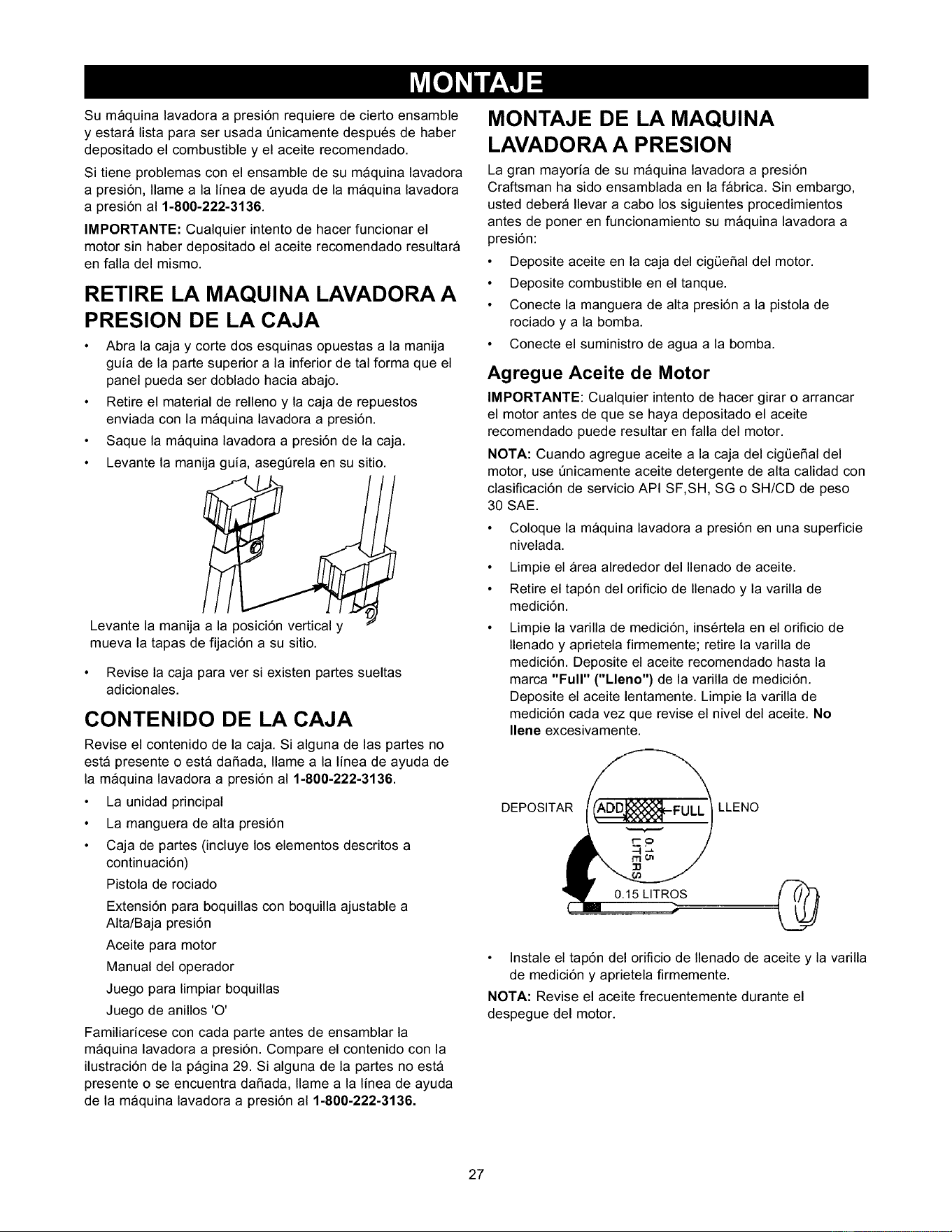
• Levante la manija guia, asegerela en su sitio.
Levante la manija a la posici6n vertical y
mueva la tapas de fijaci6n a su sitio.
• Revise la caja para ver si existen partes sueltas
adicionales.
CONTENIDO DE LA CAJA
Revise el contenido de la caja. Si alguna de las partes no
esta presente o esta dafiada, Ilame a la linea de ayuda de
la maquina lavadora a presi6n al 1-81)0-222-3136.
• La unidad principal
• La manguera de alta presi6n
• Caja de partes (incluye los elementos descritos a
continuaci6n)
Pistola de rociado
Extensi6n para boquillas con boquilla ajustable a
Alta/Baja presi6n
Aceite para motor
Manual del operador
Juego para limpiar boquillas
Juego de anillos 'O'
Familiaricese con cada parte antes de ensamblar la
maquina lavadora a presi6n. Compare el contenido con la
ilustraci6n de la pagina 29. Si alguna de la partes no esta
presente o se encuentra dafiada, Ilame a la linea de ayuda
de la maquina lavadora a presi6n al 1-81)0-222-3136.
MONTAJE DE LA MAQUINA
LAVADORA A PRESION
La gran mayoria de su maquina lavadora a presi6n
Craftsman ha sido ensamblada en la fabrica. Sin embargo,
usted debera Ilevar a cabo los siguientes procedimientos
antes de poner en funcionamiento su maquina lavadora a
presi6n:
• Deposite aceite en la caja del cigOefial del motor.
• Deposite combustible en el tanque.
• Conecte la manguera de alta presi6n a la pistola de
rociado y a la bomba.
• Conecte el suministro de agua a la bomba.
Agregue Aceite de Motor
IMPORTANTE: Cualquier intento de hacer girar o arrancar
el motor antes de que se haya depositado el aceite
recomendado puede resultar en falla del motor.
NOTA: Cuando agregue aceite a la caja del cigL_efial del
motor, use enicamente aceite detergente de alta calidad con
clasificaci6n de servicio API SF,SH, SG o SH/CD de peso
30 SAE.
• Coloque la maquina lavadora a presi6n en una superficie
nivelada.
Limpie el Area alrededor del Ilenado de aceite.
Retire el tap6n del orificio de Ilenado y la varilla de
medici6n.
Limpie la varilla de medici6n, ins6rtela en el orificio de
Ilenado y aprietela firmemente; retire la varilla de
medici6n. Deposite el aceite recomendado hasta la
marca "Full" ("Lleno") de la varilla de medici6n.
Deposite el aceite lentamente. Limpie la varilla de
medici6n cada vez que revise el nivel del aceite. No
Ilene excesivamente.
DEPOSITAR LLENO
0.15 LITROS
• Instale el tap6n del orificio de Ilenado de aceite y la varilla
de medici6n y aprietela firmemente.
NOTA: Revise el aceite frecuentemente durante el
despegue del motor.
27
Agregue Gasolina
,_ iPELIGRO! Nunca Ilene el tanque de combustible
en recintos cerrados. Nunca Ilene el tanque de
combustible cuando el motor est6 funcionando o est6
caliente. No fume cuando est6 Ilenando el tanque de
combustible.
,_ iADVERTENClA! Nunca Ilene por completo el
tanque de combustible. Deje espacio para la
expansi6n del combustible. Limpie cualquier derrame
de combustible del motor y del equipo antes de darle
arranque a la unidad.
• Use combustible limpio y almac6nelo en recipientes
cubiertos, limpios y aprobados. Utilice embudos limpios.
Nunca utilice gasolina "vieja" dejada de la estaci6n
anterior o gasolina almacenada por periodos de tiempo
prolongados.
• Limpie el area alrededor de la tapa de Ilenado del
combustible, retire la tapa.
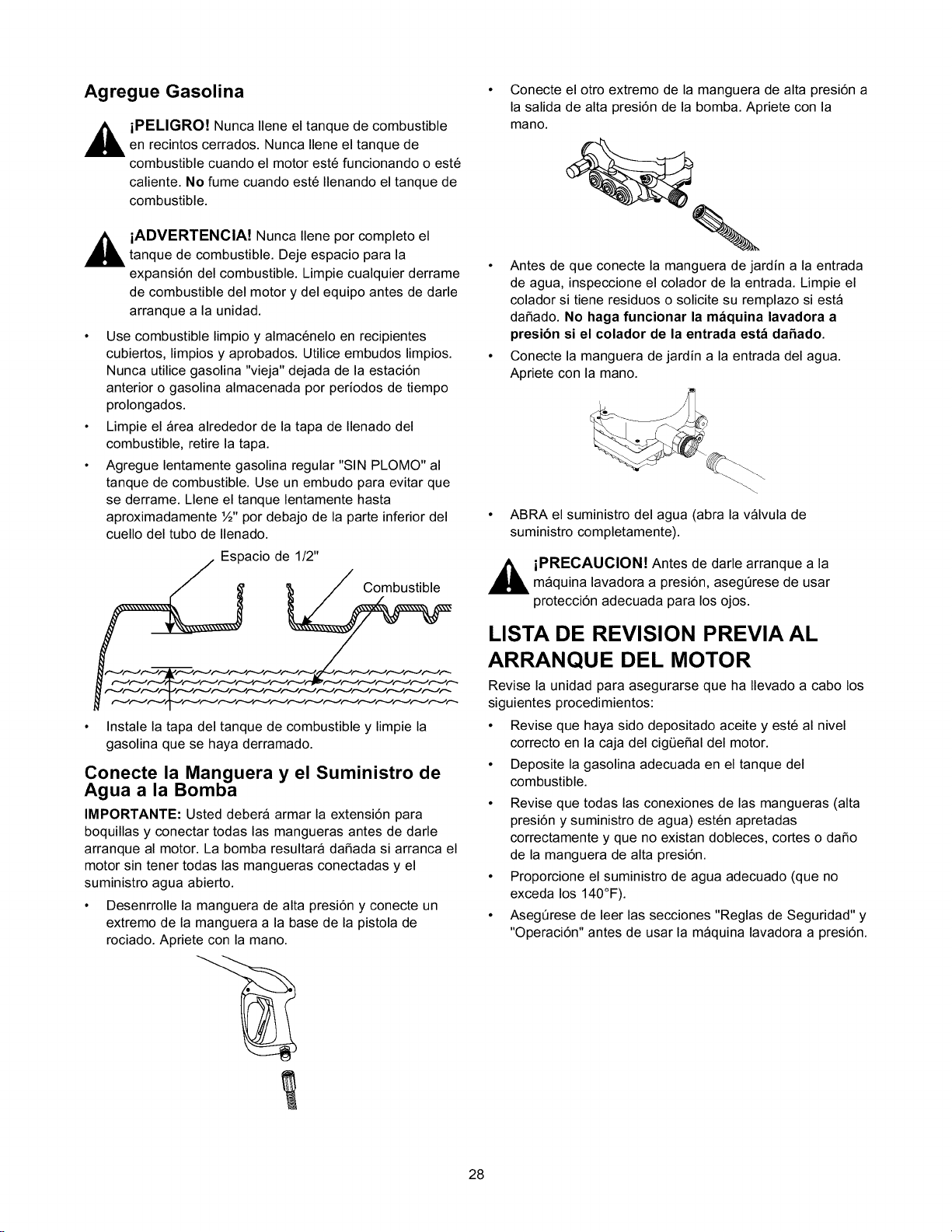
• Agregue lentamente gasolina regular"SIN PLOMO" al
tanque de combustible. Use un embudo para evitar que
se derrame. Llene el tanque lentamente hasta
aproximadamente ½" por debajo de la parte inferior del
cuello del tubo de Ilenado.
Espacio de 1/2"
Combustible
• Instale la tapa del tanque de combustible y limpie la
gasolina que se haya derramado.
Conecte la Manguera y el Suministro de
Agua a la Bomba
IMPORTANTE: Usted debera armar la extensi6n para
boquillas y conectar todas las mangueras antes de darle
arranque al motor. La bomba resultara daSada si arranca el
motor sin tener todas las mangueras conectadas y el
suministro agua abierto.
• Desenrrolle la manguera de alta presi6n y conecte un
extremo de la manguera a la base de la pistola de
rociado. Apriete con la mano.
• Conecte el otto extremo de la manguera de alta presi6n a
la salida de alta presi6n de la bomba. Apriete con la
mano.
• Antes de que conecte la manguera de jardin a la entrada
de agua, inspeccione el colador de la entrada. Limpie el
colador si tiene residuos o solicite su remplazo siesta
daSado. No haga funcionar la m_quina lavadora a
presibn si el colador de la entrada est_ daSado.
• Conecte la manguera de jardin a la entrada del agua.
Apriete con la mano.
ABRA el suministro del agua (abra la valvula de
suministro completamente).
,_ iPRECAUCION! Antes de darle arranque a la
maquina lavadora a presi6n, asegQrese de usar
protecci6n adecuada para los ojos.
LISTA DE REVISION PREVIA AL
ARRANQUE DEL MOTOR
Revise la unidad para asegurarse que ha Ilevado a cabo los
siguientes procedimientos:
• Revise que haya sido depositado aceite y est6 al nivel
correcto en la caja del cigQeSal del motor.
• Deposite la gasolina adecuada en el tanque del
combustible.
• Revise que todas las conexiones de las mangueras (alta
presi6n y suministro de agua) est6n apretadas
correctamente y que no existan dobleces, cortes o daSo
de la manguera de alta presi6n.
• Proporcione el suministro de agua adecuado (que no
exceda los 140°F).
• AsegQrese de leer las secciones "Reglas de Seguridad" y
"Operaci6n" antes de usar la maquina lavadora a presi6n.
28
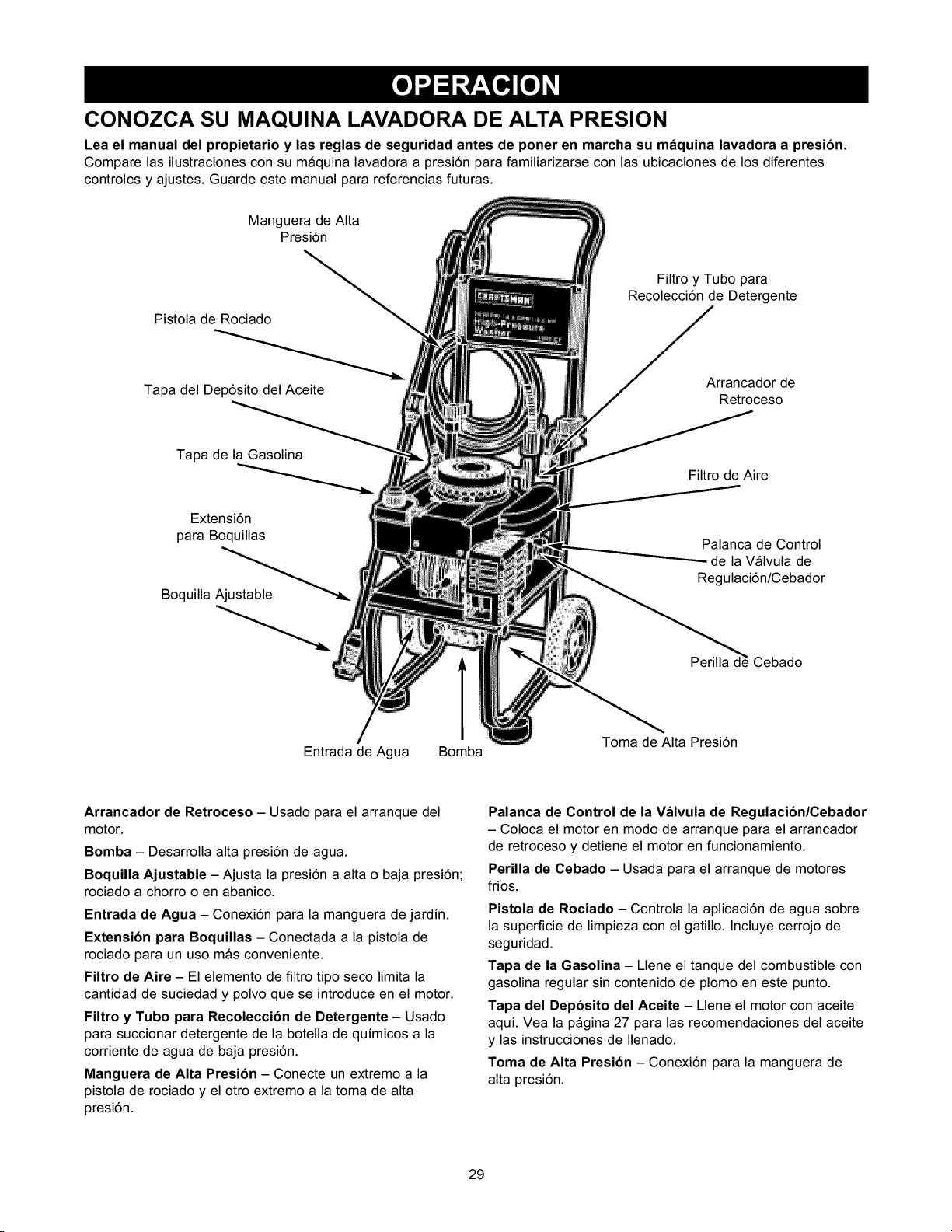
CONOZCA SU MAQUINA LAVADORA DE ALTA PRESION
Lea el manual del propietario y las reglas de seguridad antes de poner en marcha su maquina lavadora a presion.
Compare las ilustraciones con su maquina lavadora a presiOn para familiarizarse con las ubicaciones de los diferentes
controles y ajustes. Guarde este manual para referencias futuras.
Manguera de Alta
PresiOn
Pistola de Rociado
Tapa del DepOsito del Aceite
Filtro y Tubo para
RecolecciOn de Detergente
Arrancador de
Retroceso
Tapa de la Gasolina
ExtensiOn
para Boquillas
Boquilla Ajustable
Filtro de Aire
Palanca de Control
de la Valvula de
RegulaciOn/Cebador
Perilla d_ Cebado
Entrada de Agua Bomba
Toma de Alta PresiOn
Arrancador de Retroceso - Usado para el arranque del
motor.
Bomba - Desarrolla alta presiOn de agua.
Boquilla Ajustable - Ajusta la presiOn a alta o baja presiOn;
rociado a chorro o en abanico.
Entrada de Agua - ConexiOn para la manguera de jardin.
ExtensiOn para Boquillas - Conectada a la pistola de
rociado para un uso mas conveniente.
Filtro de Aire - El elemento de filtro tipo seco limita la
cantidad de suciedad y polvo que se introduce en el motor.
Filtro y Tubo para Recoleccion de Detergente - Usado
para succionar detergente de la botella de quimicos a la
corriente de agua de baja presiOn.
Manguera de Alta Presion - Conecte un extremo a la
pistola de rociado y el otro extremo a la toma de alta
presiOn.
Palanca de Control de la Valvula de Regulacion/Cebador
- Coloca el motor en modo de arranque para el arrancador
de retroceso y detiene el motor en funcionamiento.
Perilla de Cebado - Usada para el arranque de motores
frios.
Pistola de Rociado - Controla la aplicaciOn de agua sobre
la superficie de limpieza con el gatillo. Incluye cerrojo de
seguridad.
Tapa de la Gasolina - Llene el tanque del combustible con
gasolina regular sin contenido de plomo en este punto.
Tapa del Deposito del Aceite - Llene el motor con aceite
aqui. Vea la pagina 27 para las recomendaciones del aceite
y las instrucciones de Ilenado.
Toma de Alta Presion - ConexiOn para la manguera de
alta presiOn.
29
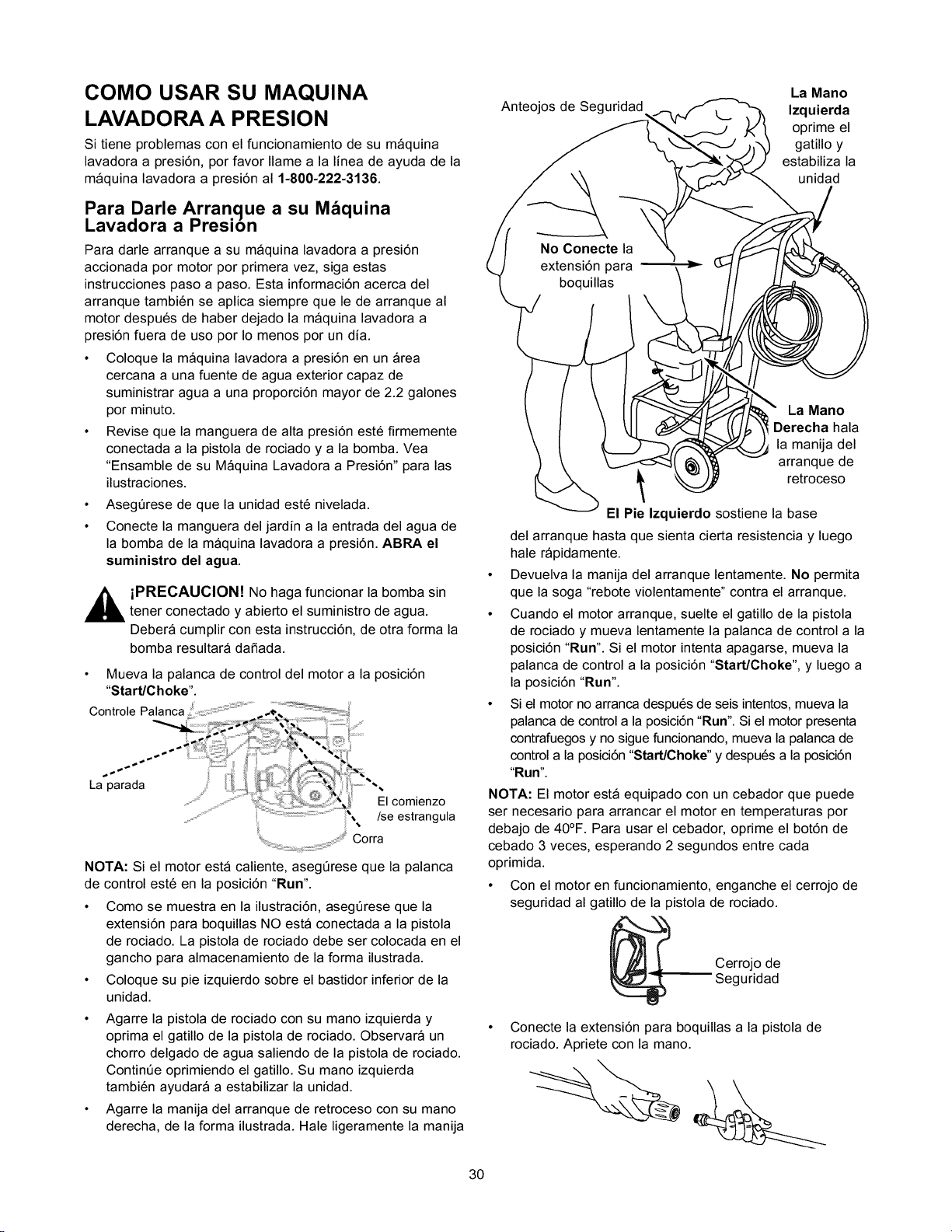
COMO USAR SU MAQUINA
LAVADORA A PRESION
Si tiene problemas con el funcionamiento de su maquina
lavadora a presi6n, por favor Ilame a la linea de ayuda de la
maquina lavadora a presi6n al 1-81)0-222-3136.
Para Darle Arranque a su M_quina
Lavadora a Presion
Para darle arranque a su maquina lavadora a presi6n
accionada por motor por primera vez, siga estas
instrucciones paso a paso. Esta informaci6n acerca del
arranque tambi6n se aplica siempre que le de arranque al
motor despu6s de haber dejado la maquina lavadora a
presi6n fuera de uso por Io menos por un dia.
• Coloque la maquina lavadora a presi6n en un area
cercana a una fuente de agua exterior capaz de
suministrar agua a una proporci6n mayor de 2.2 galones
pot minuto.
• Revise que la manguera de alta presi6n est6 flrmemente
conectada a la pistola de rociado y a la bomba. Vea
"Ensamble de su Maquina Lavadora a Presi6n" para las
ilustraciones.
• Aseg6rese de que la unidad est6 nivelada.
• Conecte la manguera del jardin a la entrada del agua de
la bomba de la maquina lavadora a presi6n. ABRA el
suministro del agua.
,_ iPRECAUCION! No haga funcionar la bomba sin
tener conectado y abierto el suministro de agua.
Debera cumplir con esta instrucci6n, de otra forma la
bomba resultara daSada.
• Mueva la palanca de control del motor a la posici6n
"Start/Choke".
! 4
"-. Corra
....:;, i; ,%,,,,,
NOTA: Si el motor esta caliente, aseg6rese que la palanca
de control este en la posici6n "Run".
• Como se muestra en la ilustraci6n, asegerese que la
extensi6n para boquillas NO esta conectada a la pistola
de rociado. La pistola de rociado debe set colocada en el
gancho para almacenamiento de la forma ilustrada.
• Coloque su pie izquierdo sobre el bastidor inferior de la
unidad.
• Agarre la pistola de rociado con su mano izquierda y
optima el gatillo de la pistola de rociado. Observara un
chorro delgado de agua saliendo de la pistola de rociado.
Contin6e oprimiendo el gatillo. Su mano izquierda
tambi6n ayudara a estabilizar la unidad.
• Agarre la manija del arranque de retroceso con su mano
derecha, de la forma ilustrada. Hale ligeramente la manija
Anteojos de Seguridad
La Mano
Izquierda
oprime el
gatillo y
estabiliza la
unidad
La Mano
Derecha hala
la manija del
arranque de
retroceso
El Pie Izquierdo sostiene la base
del arranque hasta que sienta cierta resistencia y luego
hale rapidamente.
• Devuelva la manija del arranque lentamente. No permita
que la soga "rebote violentamente" contra el arranque.
• Cuando el motor arranque, suelte el gatillo de la pistola
de rociado y mueva lentamente la palanca de control a la
posici6n "Run". Si el motor intenta apagarse, mueva la
palanca de control a la posici6n "Start/Choke", y luego a
la posici6n "Run".
• Si el motor no arranca despu6s de seis intentos, mueva la
palanca de control a la posici6n "Run". Si el motor presenta
contrafuegos y no sigue funcionando, mueva la palanca de
control a la posici6n "Start/Choke" y despu6s a la posici6n
"Run".
NOTA: El motor esta equipado con un cebador que puede
ser necesario para arrancar el motor en temperaturas por
debajo de 40°F. Para usar el cebador, oprime el bot6n de
cebado 3 veces, esperando 2 segundos entre cada
oprimida.
• Con el motor en funcionamiento, enganche el cerrojo de
seguridad al gatillo de la pistola de rociado.
Cerrojo de
uridad
Conecte la extensi6n para boquillas a la pistola de
rociado. Apriete con la mano.
30
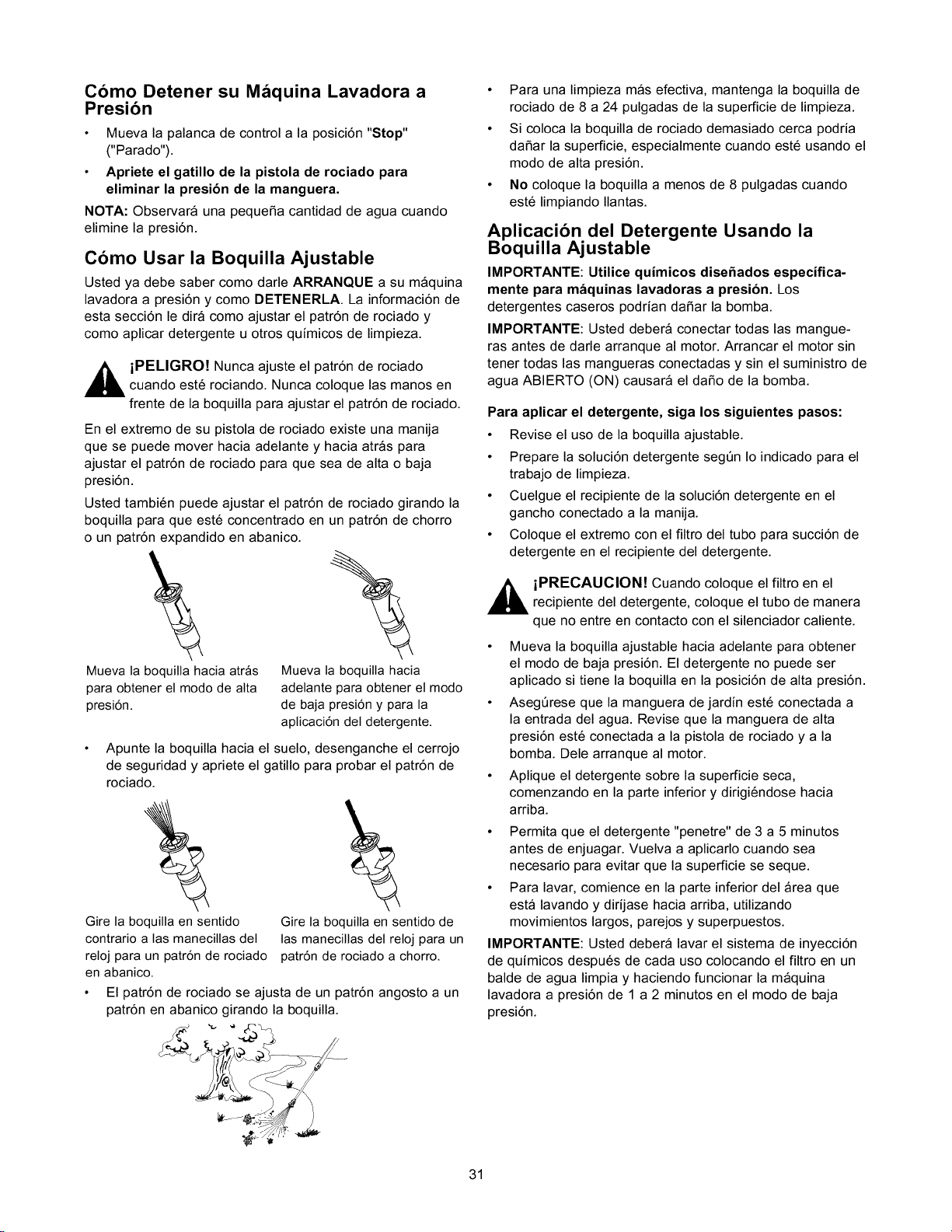
Como Detener su M_quina Lavadora a
Presion
• Mueva la palanca de control a la posici6n "Stop"
("Parado").
• Apriete el gatillo de la pistola de rociado para
eliminar la presi6n de la manguera.
NOTA: Observara una pequeSa cantidad de agua cuando
elimine la presi6n.
Como Usar la Boquilla Ajustable
Usted ya debe saber como darle ARRANQUE a su maquina
lavadora a presi6n y como DETENERLA. La informaci6n de
esta secci6n le dira como ajustar el patr6n de rociado y
como aplicar detergente u otros quimicos de limpieza.
,_ iPELIGRO! Nunca ajuste el patr6n de rociado
cuando est6 rociando. Nunca coloque las manos en
frente de la boquilla para ajustar el patr6n de rociado.
En el extremo de su pistola de rociado existe una manija
que se puede mover hacia adelante y hacia atras para
ajustar el patr6n de rociado para que sea de alta o baja
presi6n.
Usted tambi6n puede ajustar el patr6n de rociado girando la
boquilla para que est6 concentrado en un patr6n de chorro
o un patr6n expandido en abanico.
Mueva la boquilla hacia atrfis
para obtener el modo de alta
presiSn.
"%
Mueva Ia boquilIa hacia
adelante para obtener el modo
de baja presi6n y para Ia
aplicaci6n del detergente.
• Apunte la boquilla hacia el suelo, desenganche el cerrojo
de seguridad y apriete el gatillo para probar el patr6n de
rociado.
Gire la boquilla en sentido
contrario alas manecilIas deI
reloj para un patr6n de rociado
en abanico.
Gire la boquilla en sentido de
Ias manecillas del reloj para un
patr6n de rociado a chorro.
El patr6n de rociado se ajusta de un patr6n angosto a un
patr6n en abanico girando la boquilla.
• Para una limpieza mas efectiva, mantenga la boquilla de
rociado de 8 a 24 pulgadas de la superficie de limpieza.
• Si coloca la boquilla de rociado demasiado cerca podria
daSar la superficie, especialmente cuando est6 usando el
modo de alta presi6n.
• No coloque la boquilla a menos de 8 pulgadas cuando
est6 limpiando Ilantas.
Aplicacion del Detergente Usando la
Boquilla Ajustable
IMPORTANTE: Utilice quimicos disehados especifica-
mente para maquinas lavadoras a presion. Los
detergentes caseros podrian da_ar la bomba.
IMPORTANTE: Usted debera conectar todas las mangue-
ras antes de darle arranque al motor. Arrancar el motor sin
tener todas las mangueras conectadas y sin el suministro de
agua ABIERTO (ON) causara el daSo de la bomba.
Para aplicar el detergente, siga los siguientes pasos:
• Revise el uso de la boquilla ajustable.
• Prepare la soluci6n detergente segt_n Io indicado para el
trabajo de limpieza.
• Cuelgue el recipiente de la soluci6n detergente en el
gancho conectado a la manija.
• Coloque el extremo con el filtro del tubo para succi6n de
detergente en el recipiente del detergente.
,_ iPRECAUClON! Cuando coloque el filtro en el
recipiente del detergente, coloque el tubo de manera
que no entre en contacto con el silenciador caliente.
• Mueva la boquilla ajustable hacia adelante para obtener
el modo de baja presi6n. El detergente no puede set
aplicado si tiene la boquilla en la posici6n de alta presi6n.
• Asegt_rese que la manguera de jardin est6 conectada a
la entrada del agua. Revise que la manguera de alta
presi6n est6 conectada a la pistola de rociado y a la
bomba. Dele arranque al motor.
• Aplique el detergente sobre la superficie seca,
comenzando en la parte inferior y dirigi6ndose hacia
arriba.
• Permita que el detergente "penetre" de 3 a 5 minutos
antes de enjuagar. Vuelva a aplicarlo cuando sea
necesario para evitar que la superficie se seque.
• Para lavar, comience en la parte inferior del area que
esta lavando y dirijase hacia arriba, utilizando
movimientos largos, parejos y superpuestos.
IMPORTANTE: Usted debera lavar el sistema de inyecci6n
de quimicos despu6s de cada uso colocando el filtro en un
balde de agua limpia y haciendo funcionar la maquina
lavadora a presi6n de 1 a 2 minutos en el modo de baja
presi6n.
31
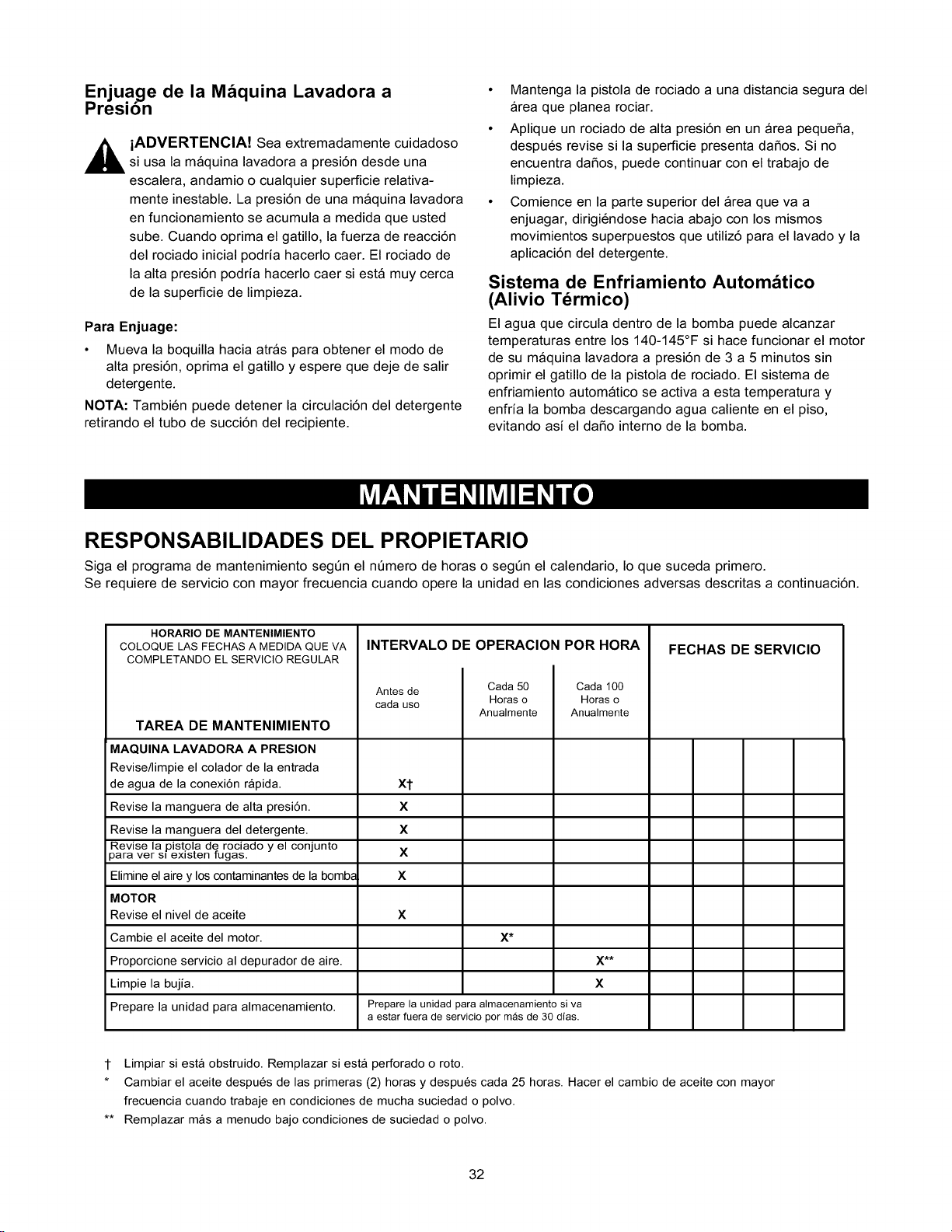
Enjuage de la M_quina Lavadora a
Presion
iADVERTENCIA! Sea extremadamente cuidadoso
si usa la maquina lavadora a presi6n desde una
escalera, andamio o cualquier superficie relativa-
mente inestable. La presi6n de una maquina lavadora
en funcionamiento se acumula a medida que usted
sube. Cuando oprima el gatillo, la fuerza de reacci6n
del rociado inicial podria hacerlo caer. El rociado de
la alta presi6n podria hacerlo caer siesta muy cerca
de la superficie de limpieza.
Para Enjuage:
• Mueva la boquilla hacia atras para obtener el modo de
alta presi6n, oprima el gatillo y espere que deje de salir
detergente.
NOTA: Tambi6n puede detener la circulaci6n del detergente
retirando el tubo de succi6n del recipiente.
• Mantenga la pistola de rociado a una distancia segura del
area que planea rociar.
• Aplique un rociado de alta presi6n en un area pequeSa,
despu6s revise si la superficie presenta daSos. Si no
encuentra daSos, puede continuar con el trabajo de
limpieza.
• Comience en la parte superior del area que va a
enjuagar, dirigi6ndose hacia abajo con los mismos
movimientos superpuestos que utiliz6 para el lavado y la
aplicaci6n del detergente.
Sistema de Enfriamiento Autom&tico
(Alivio Tdrmico)
El agua que circula dentro de la bomba puede alcanzar
temperaturas entre los 140-145°F si hace funcionar el motor
de su maquina lavadora a presi6n de 3 a 5 minutos sin
oprimir el gatillo de la pistola de rociado. El sistema de
enfriamiento automatico se activa a esta temperatura y
enfria la bomba descargando agua caliente en el piso,
evitando asi el daSo interno de la bomba.
RESPONSABILIDADES DEL PROPIETARIO
Siga el programa de mantenimiento segt_n el nt_mero de horas o segt_n el calendario, Io que suceda primero.
Se requiere de servicio con mayor frecuencia cuando opere la unidad en las condiciones adversas descritas a continuaci6n.
HORARIO DE MANTENIMIENTO
COLOQUE LAS FECHAS A MEDtDA QUE VA
COMPLETANDO EL SERVICIO REGULAR
INTERVALO DE OPERACION POR HORA
Antes de
cada use
Cada 50
Horas o
Anualmente
Cada 100
Horas o
Anualmente
TAREA DE MANTENIMIENTO
MAQUINA LAVADORA A PRESION
Revise/limpieel coladorde la entrada
de agua de la conexi6n rapida, xt
Revise la manguera de alta presi6n. X
Revise la manguera del detergente. X
Revise la pistola de rociado y el conjunto
3ara ver si existen tugas. X
Elimineel airey los contaminantesde la bomba X
MOTOR
Revise el nivel de aceite X
Cambie el aceite del motor. X*
Proporcione servicio al depurador de aire. X**
Limpie la bujia. X
Prepare la unidad para almacenamiento. Prepare la unidad para almacenamiento si va
a estar fuera de servicio per m_s de 30 dfas.
FECHAS DE SERVIClO
1 Limpiar siesta obstruido. Remplazar siesta perforado o roto.
* Cambiar el aceite despues de las primeras (2) horas y despues cada 25 horas. Hacer el cambio de aceite con mayor
frecuencia cuando trabaje en condiciones de mucha suciedad o polvo.
** Remplazar mas a menudo bajo condiciones de suciedad o polvo.
32
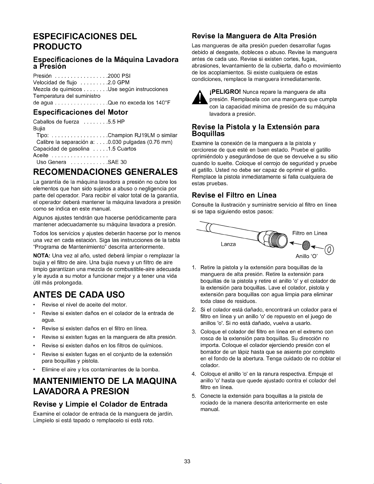
ESPECIFICACIONES DEL
PRODUCTO
Especificaciones de la M_quina Lavadora
a _'resibn
Presi6n ................. 2000 PSI
Velocidad de flujo ......... 2.0 GPM
Mezcla de quimicos ........ Use segQn instrucciones
Temperatura del suministro
de agua ................. Que no exceda los 140°F
Especificaciones del Motor
Caballos de fuerza ........ 5.5 HP
Bujia
Tipo: .................. Champion RJ19LM o similar
Calibre la separaci6n a: .... 0.030 pulgadas (0.76 mm)
Capacidad de gasolina ..... 1.5 Cuartos
Aceite ..................
Uso Genera ............ SAE 30
RECOMENDACIONES GENERALES
La garantia de la maquina lavadora a presi6n no cubre los
elementos que han sido sujetos a abuso o negligencia por
parte del operador. Para recibir el valor total de la garantia,
el operador debera mantener la maquina lavadora a presi6n
como se indica en este manual.
Algunos ajustes tendran que hacerse peri6dicamente para
mantener adecuadamente su maquina lavadora a presi6n.
Todos los servicios y ajustes deberan hacerse por Io menos
una vez en cada estaci6n. Siga las instrucciones de la tabla
"Programa de Mantenimiento" descrita anteriormente.
NOTA: Una vez al aSo, usted debera limpiar o remplazar la
bujia y el filtro de aire. Una bujia nueva y un filtro de aire
limpio garantizan una mezcla de combustible-aire adecuada
y le ayuda a su motor a funcionar mejor y a tener una vida
Qtil mas prolongada.
ANTES DE CADA USO
• Revise el nivel de aceite del motor.
• Revise si existen daSos en el colador de la entrada de
agua.
• Revise si existen daSos en el filtro en linea.
• Revise si existen fugas en la manguera de alta presi6n.
• Revise si existen daSos en los filtros de quimicos.
• Revise si existen fugas en el conjunto de la extensi6n
para boquillas y pistola.
• Elimine el aire y los contaminantes de la bomba.
MANTENIMIENTO DE LA MAQUINA
LAVADORA A PRESION
Revise y Limpie el Colador de Entrada
Examine el colador de entrada de la manguera de jardin.
Limpielo siesta tapado o remplacelo si esta roto.
Revise la Manguera de Alta Presion
Las mangueras de alta presi6n pueden desarrollar fugas
debido al desgaste, dobleces o abuso. Revise la manguera
antes de cada uso. Revise si existen cortes, fugas,
abrasiones, levantamiento de la cubierta, daSo o movimiento
de los acoplamientos. Si existe cualquiera de estas
condiciones, remplace la manguera inmediatamente.
iPELIGRO! Nunca repare la manguera de alta
presi6n. Remplacela con una manguera que cumpla
con la capacidad minima de presi6n de su maquina
lavadora a presi6n.
Revise la Pistola y la Extension para
Boquillas
Examine la conexi6n de la manguera a la pistola y
cerciorese de que est6 en buen estado. Pruebe el gatillo
oprimi6ndolo y asegurandose de que se devuelve a su sitio
cuando Io suelte. Coloque el cerrojo de seguridad y pruebe
el gatillo. Usted no debe ser capaz de oprimir el gatillo.
Remplace la pistola inmediatamente si falla cualquiera de
estas pruebas.
Revise el Filtro en Linea
Consulte la ilustraci6n y suministre servicio al filtro en linea
si se tapa siguiendo estos pasos:
Lanza
Filtro en Linea
Anillo 'O'
1. Retire la pistola y la extensi6n para boquillas de la
manguera de alta presi6n. Retire la extensi6n para
boquillas de la pistola y retire el anillo 'o' y el colador de
la extensi6n para boquillas. Lave el colador, pistola y
extensi6n para boquillas con agua limpia para eliminar
toda clase de residuos.
2. Si el colador esta daSado, encontrara un colador para el
filtro en linea y un anillo 'o' de repuesto en el juego de
anillos 'o'. Si no esta daSado, vuelva a usarlo.
3. Coloque el colador del filtro en linea en el extremo con
rosca de la extensi6n para boquillas. Su direcci6n no
importa. Coloque el colador ejerciendo presi6n con el
borrador de un lapiz hasta que se asiente pot completo
en el fondo de la abertura. Tenga cuidado de no doblar el
colador.
4.
5.
Coloque el anillo 'o' en la ranura respectiva. Empuje el
anillo 'o' hasta que quede ajustado contra el colador del
filtro en linea.
Conecte la extensi6n para boquillas a la pistola de
rociado de la manera descrita anteriormente en este
manual.
33
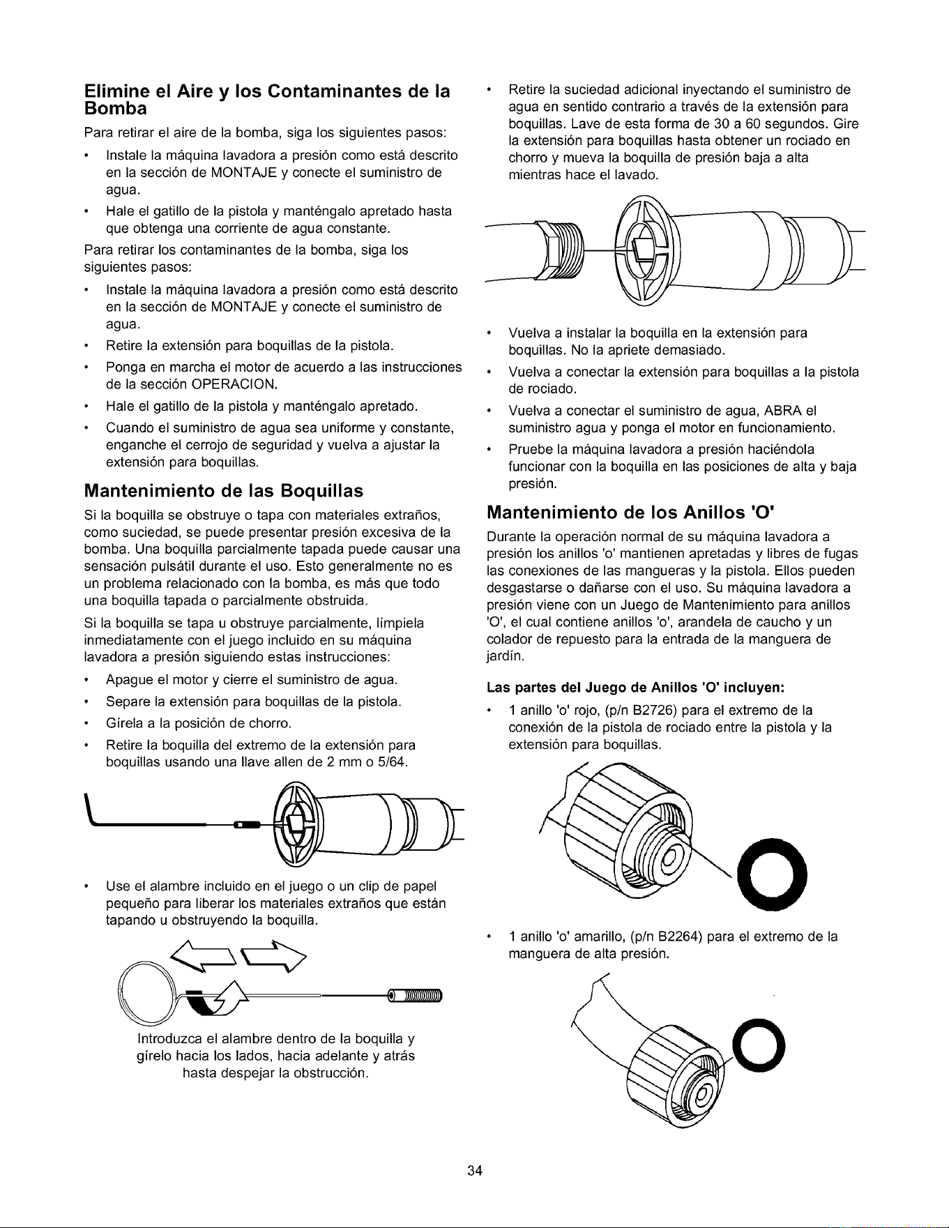
Elimine el Aire y los Contaminantes de la
Bomba
Para retirar el aire de la bomba, siga los siguientes pasos:
• Instale la maquina lavadora a presi6n como esta descrito
en la secci6n de MONTAJE y conecte el suministro de
agua.
• Hale el gatillo de la pistola y mant6ngalo apretado hasta
que obtenga una corriente de agua constante.
Para retirar los contaminantes de la bomba, siga los
siguientes pasos:
• Instale la maquina lavadora a presi6n como esta descrito
en la secci6n de MONTAJE y conecte el suministro de
agua.
• Retire la extensi6n para boquillas de la pistola.
• Ponga en marcha el motor de acuerdo a las instrucciones
de la secci6n OPERAClON.
Hale el gatillo de la pistola y mant6ngalo apretado.
Cuando el suministro de agua sea uniforme y constante,
enganche el cerrojo de seguridad y vuelva a ajustar la
extensi6n para boquillas.
Mantenimiento de las Boquillas
Si la boquilla se obstruye o tapa con materiales extraSos,
como suciedad, se puede presentar presi6n excesiva de la
bomba. Una boquilla parcialmente tapada puede causar una
sensaci6n pulsatil durante el uso. Esto generalmente no es
un problema relacionado con la bomba, es masque todo
una boquilla tapada o parcialmente obstruida.
Si la boquilla se tapa u obstruye parcialmente, limpiela
inmediatamente con el juego incluido en su maquina
lavadora a presi6n siguiendo estas instrucciones:
• Apague el motor y cierre el suministro de agua.
• Separe la extensi6n para boquillas de la pistola.
• Girela a la posici6n de chorro.
• Retire la boquilla del extremo de la extensi6n para
boquillas usando una Ilave allen de 2 mm o 5/64.
t
• Use el alambre incluido en el juego o un clip de papel
pequeSo para liberar los materiales extraSos que estan
tapando u obstruyendo la boquilla.
Retire la suciedad adicional inyectando el suministro de
agua en sentido contrario a trav6s de la extensi6n para
boquillas. Lave de esta forma de 30 a 60 segundos. Gire
la extensi6n para boquillas hasta obtener un rociado en
chorro y mueva la boquilla de presi6n baja a alta
mientras hace el lavado.
• Vuelva a instalar la boquilla en la extensi6n para
boquillas. No la apriete demasiado.
• Vuelva a conectar la extensi6n para boquillas a la pistola
de rociado.
Vuelva a conectar el suministro de agua, ABRA el
suministro agua y ponga el motor en funcionamiento.
Pruebe la maquina lavadora a presi6n haci6ndola
funcionar con la boquilla en las posiciones de alta y baja
presi6n.
Mantenimiento de los Anillos '0'
Durante la operaci6n normal de su maquina lavadora a
presi6n los anillos 'o' mantienen apretadas y libres de fugas
las conexiones de las mangueras y la pistola. EIIos pueden
desgastarse o daSarse con el uso. Su maquina lavadora a
presi6n viene con un Juego de Mantenimiento para anillos
'O', el cual contiene anillos 'o', arandela de caucho y un
colador de repuesto para la entrada de la manguera de
jardin.
Las partes del Juego de Anillos 'O' incluyen:
• 1 anillo 'o' rojo, (p/n B2726) para el extremo de la
conexi6n de la pistola de rociado entre la pistola y la
extensi6n para boquillas.
O
1 anillo 'o' amarillo, (p/n B2264) para el extremo de la
manguera de alta presi6n.
Introduzca el alambre dentro de la boquilla y
girelo hacia los lados, hacia adelante y atras
hasta despejar la obstrucci6n.
34
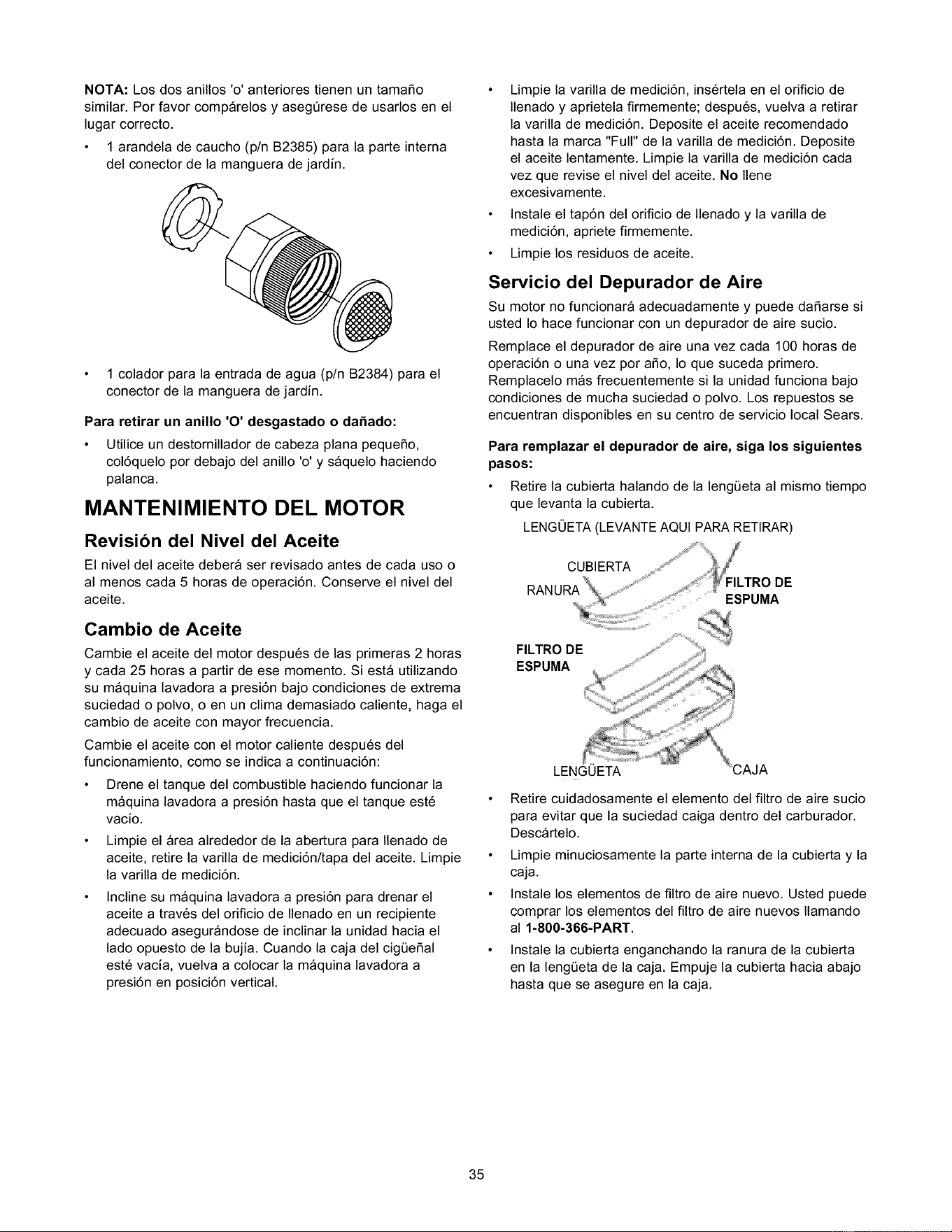
NOTA:Losdosanillos'o'anteriorestienenuntamaSo
similar.Porfavorcomparelosyaseg6resedeusarlosenel
lugarcorrecto.
• 1arandeladecaucho(p/nB2385)paralaparteinterna
delconectordelamangueradejardin.
• 1coladorparalaentradadeagua(p/nB2384)parael
conectordelamangueradejardin.
Para retirar un anillo 'O' desgastado o daSado:
• Utilice un destornillador de cabeza plana pequeSo,
col6quelo por debajo del anillo 'o' y saquelo haciendo
palanca.
MANTENIMIENTO DEL MOTOR
Revision del Nivel del Aceite
El nivel del aceite debera ser revisado antes de cada uso o
al menos cada 5 horas de operaci6n. Conserve el nivel del
aceite.
Cambio de Aceite
Cambie el aceite del motor despu6s de las primeras 2 horas
y cada 25 horas a partir de ese momento. Siesta utilizando
su maquina lavadora a presi6n bajo condiciones de extrema
suciedad o polvo, o en un clima demasiado caliente, haga el
cambio de aceite con mayor frecuencia.
Cambie el aceite con el motor caliente despu6s del
funcionamiento, como se indica a continuaci6n:
• Drene el tanque del combustible haciendo funcionar la
maquina lavadora a presi6n hasta que el tanque est6
vacio.
• Limpie el area alrededor de la abertura para Ilenado de
aceite, retire la varilla de medici6n/tapa del aceite. Limpie
la varilla de medici6n.
Incline su maquina lavadora a presi6n para drenar el
aceite a trav6s del orificio de Ilenado en un recipiente
adecuado asegurandose de inclinar la unidad hacia el
lado opuesto de la bujia. Cuando la caja del cig_eSal
est6 vacia, vuelva a colocar la maquina lavadora a
presi6n en posici6n vertical.
• Limpie la varilla de medici6n, ins6rtela en el orificio de
Ilenado y aprietela firmemente; despu6s, vuelva a retirar
la varilla de medici6n. Deposite el aceite recomendado
hasta la marca "Full" de la varilla de medici6n. Deposite
el aceite lentamente. Limpie la varilla de medici6n cada
vez que revise el nivel del aceite. No Ilene
excesivamente.
• Instale el tap6n del orificio de Ilenado y la varilla de
medici6n, apriete firmemente.
• Limpie los residuos de aceite.
Servicio del Depurador de Aire
Su motor no funcionara adecuadamente y puede da_arse si
usted Io hace funcionar con un depurador de aire sucio.
Remplace el depurador de aire una vez cada 100 horas de
operaci6n o una vez por aSo, Io que suceda primero.
Remplacelo mas frecuentemente si la unidad funciona bajo
condiciones de mucha suciedad o polvo. Los repuestos se
encuentran disponibles en su centro de servicio local Sears.
Para remplazar el depurador de aire, siga los siguientes
pasos:
• Retire la cubierta halando de la leng_eta al mismo tiempo
que levanta la cubierta.
LENGOETA (LEVANTE AQUI PARA RETIRAR)
CUBIERTA
RANURA DE
ESPUMA
FILTRO DE
ESPUMA
LENGUETA
Retire cuidadosamente el elemento del filtro de aire sucio
para evitar que la suciedad caiga dentro del carburador.
Descartelo.
• Limpie minuciosamente la parte interna de la cubierta y la
caja.
• Instale los elementos de filtro de aire nuevo. Usted puede
comprar los elementos del filtro de aire nuevos Ilamando
al 1-800-366-PART.
Instale la cubierta enganchando la ranura de la cubierta
en la leng_eta de la caja. Empuje la cubierta hacia abajo
hasta que se asegure en la caja.
35
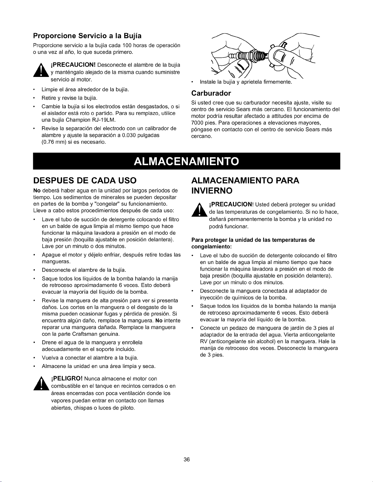
Proporcione Servicio a la Bujia
Proporcione servicio a la bujia cada 100 horas de operaci6n
o una vez al aSo, Io que suceda primero.
,_ iPRECAUCION! Desconecte el alambre de la bujia
y mant6ngalo alejado de la misma cuando suministre
servicio al motor.
• Limpie el Area alrededor de la bujia.
• Retire y revise la bujia.
• Cambie la bujia si los electrodos estan desgastados, o si
el aislador esta roto o partido. Para su remplazo, utilice
una bujia Champion RJ-19LM.
• Revise la separaci6n del electrodo con un calibrador de
alambre y ajuste la separaci6n a 0.030 pulgadas
(0.76 mm) si es necesario.
• Instale la bujia y aprietela firmemente.
Carburador
Si usted cree que su carburador necesita ajuste, visite su
centro de servicio Sears mas cercano. El funcionamiento del
motor podria resultar afectado a attitudes por encima de
7000 pies. Para operaciones a elevaciones mayores,
p6ngase en contacto con el centro de servicio Sears mas
cercano.
DESPUES DE CADA USO
No debera haber agua en la unidad por largos periodos de
tiempo. Los sedimentos de minerales se pueden depositar
en partes de la bombay "congelar" su funcionamiento.
Lleve a cabo estos procedimientos despu6s de cada uso:
• Lave el tubo de succi6n de detergente colocando el filtro
en un balde de agua limpia al mismo tiempo que hace
funcionar la maquina lavadora a presi6n en el modo de
baja presi6n (boquilla ajustable en posici6n delantera).
Lave por un minuto o dos minutos.
• Apague el motor y d6jelo enfriar, despu6s retire todas las
mangueras.
• Desconecte el alambre de la bujia.
• Saque todos los liquidos de la bomba halando la manija
de retroceso aproximadamente 6 veces. Esto debera
evacuar la mayoria del liquido de la bomba.
• Revise la manguera de alta presi6n para ver si presenta
daSos. Los cortes en la manguera o el desgaste de la
misma pueden ocasionar fugas y p6rdida de presi6n. Si
encuentra algQn daSo, remplace la manguera. No intente
reparar una manguera daSada. Remplace la manguera
con la parte Craftsman genuina.
• Drene el agua de la manguera y enrollela
adecuadamente en el soporte incluido.
• Vuelva a conectar el alambre a la bujia.
• Almacene la unidad en una Area limpia y seca.
,_ iPELIGRO! Nunca almacene el motor con
combustible en el tanque en recintos cerrados o en
Areas encerradas con poca ventilaci6n donde los
vapores puedan entrar en contacto con llamas
abiertas, chispas o luces de piloto.
ALMACENAMIENTO PARA
INVIERNO
,_ iPRECAUCION! Usted debera proteger su unidad
de las temperaturas de congelamiento. Si no Io hace,
daSarA permanentemente la bombay la unidad no
podra funcionar.
Para proteger la unidad de las temperaturas de
congelamiento:
• Lave el tubo de succi6n de detergente colocando el filtro
en un balde de agua limpia al mismo tiempo que hace
funcionar la maquina lavadora a presi6n en el modo de
baja presi6n (boquilla ajustable en posici6n delantera).
Lave por un minuto o dos minutos.
• Desconecte la manguera conectada al adaptador de
inyecci6n de quimicos de la bomba.
• Saque todos los liquidos de la bomba halando la manija
de retroceso aproximadamente 6 veces. Esto debera
evacuar la mayoria del liquido de la bomba.
• Conecte un pedazo de manguera de jardin de 3 pies al
adaptador de la entrada del agua. Vierta anticongelante
RV (anticongelante sin alcohol) en la manguera. Hale la
manija de retroceso dos veces. Desconecte la manguera
de 3 pies.
36

ALMACENAMIENTO PROLONGADO
Si usted no planea usar la maquina lavadora a presi6n por
mas de 30 dias, debera preparar el motor para un
almacenamiento prolongado.
Es importante evitar la formaci6n de dep6sitos de goma en
las partes esenciales del sistema del combustible tales
como carburador, filtro del combustible, manguera o tanque
del combustible durante el almacenamiento. Tambi6n, la
experiencia indica que los combustibles con mezclas de
alcohol (llamados gasohol, etanol o metanol) pueden atraer
la humedad, Io que Ileva a la separaci6n y formaci6n de
acidos durante el almacenamiento. La gasolina acida puede
daSar el sistema del combustible de un motor durante el
almacenamiento.
Proteja el Sistema de Combustible
Drenaje del Tanque de Combustible:
_ PELIGRO! Drene el combustible en un Area
despejada, lejos de llamas abiertas, en un recipiente
adecuado y utilizando un embudo. Aseg6rese que el
motor est6 frio. No Fume.
• Retire toda la gasolina del carburador y del tanque del
combustible para evitar la formaci6n de dep6sitos de
goma en estas pares, Io que puede causar un mal
funcionamiento del motor.
• Haga funcionar el motor hasta que el tanque quede vacio
y el motor se detenga.
Cambio de Aceite
Con el motor todavia caliente, drene el aceite de la caja del
cigiJeSal. Vuelva a Ilenarlo con el grado de aceite
recomendado. Vea "Cambio de Aceite" en la pagina 35.
Aceite el Di_metro Interior del Cilindro
• Retire la bujia. Rocie aproximadamente 1 onza de aceite
limpio para motor dentro del cilindro. Cubra el orificio de
la bujia con un trapo. Hale la manija de retroceso
lentamente para distribuir el aceite. Evite el rociado del
orificio de la bujia.
• Instale la bujia. No conecte el alambre de la bujia.
OTROS
No almacene gasolina de una estaci6n a otra.
Si es posible, almacene su unidad en un recinto cerrado
y c6brala para protegerla del polvo y la suciedad.
ASEGURESE DE VACIAR EL TANQUE DEL
COMBUSTIBLE.
IMPORTANTE: NUNCA cubra su maquina lavadora a
presi6n cuando el motor y el Area del escape est6n
calientes.
37
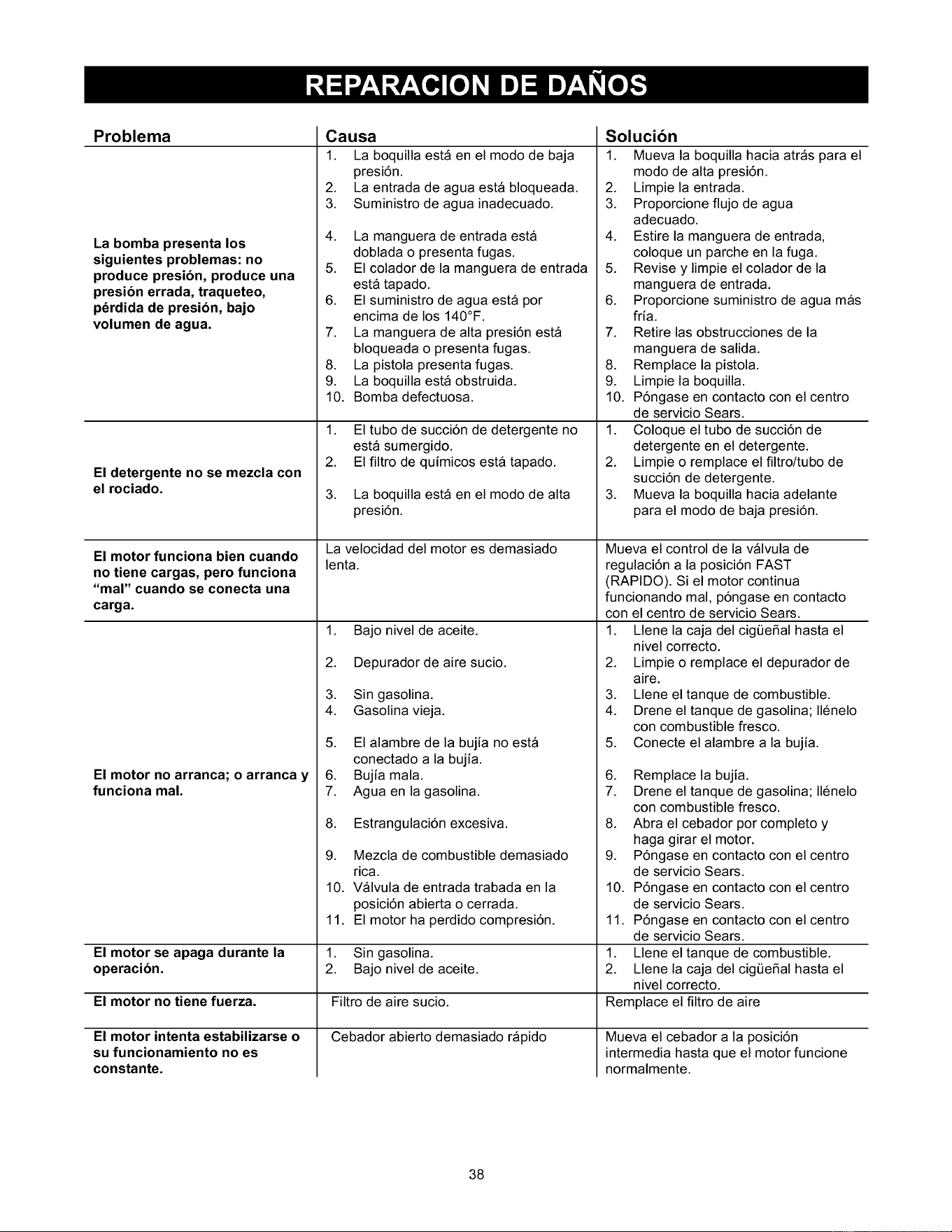
Problema
La bomba presenta los
siguientes problemas: no
produce presion, produce una
presion errada, traqueteo,
p_rdida de presion, bajo
volumen de agua.
El detergente no se mezcla con
el rociado.
El motor funciona bien cuando
no tiene cargas, pero funciona
"mal" cuando se conecta una
carga.
El motor no arranca; o arranca y
funciona mal.
Causa
1. La boquilla esta en el modo de baja
presi6n.
2. La entrada de agua esta bloqueada.
3. Suministro de agua inadecuado.
4. La manguera de entrada esta
doblada o presenta fugas.
5. El colador de la manguera de entrada
esta tapado.
6. El suministro de agua esta por
encima de los 140°F.
7. La manguera de alta presi6n esta
bloqueada o presenta fugas.
8. La pistola presenta fugas.
9. La boquilla esta obstruida.
10. Bomba defectuosa.
1.
2.
3.
El tubo de succi6n de detergente no
esta sumergido.
El filtro de quimicos esta tapado.
La boquilla esta en el modo de alta
presi6n.
La velocidad del motor es demasiado
lenta.
El motor se apaga durante la
operacion.
El motor no tiene fuerza. Filtro de aire sucio.
Cebador abierto demasiado rapido
El motor intenta estabilizarse o
su funcionamiento no es
constante.
1. Bajo nivel de aceite.
2. Depurador de aire sucio.
3. Sin gasolina.
4. Gasolina vieja.
5. El alambre de la bujia no esta
conectado a la bujia.
6. Bujia mala.
7. Agua en la gasolina.
8. Estrangulaci6n excesiva.
9. Mezcla de combustible demasiado
rica.
10. Valvula de entrada trabada en la
posici6n abierta o cerrada.
11. El motor ha perdido compresi6n.
1. Sin gasolina.
2. Bajo nivel de aceite.
Solucibn
1. Mueva la boquilla hacia atras para el
modo de alta presi6n.
2. Limpie la entrada.
3. Proporcione flujo de agua
adecuado.
4. Estire la manguera de entrada,
coloque un parche en la fuga.
5. Revise y limpie el colador de la
manguera de entrada.
6. Proporcione suministro de agua mas
fria.
7. Retire las obstrucciones de la
manguera de salida.
8. Remplace la pistola.
9. Limpie la boquilla.
10. P6ngase en contacto con el centro
de servicio Sears.
1. Coloque el tubo de succi6n de
detergente en el detergente.
2. Limpie o remplace el filtro/tubo de
succi6n de detergente.
3. Mueva la boquilla hacia adelante
para el modo de baja presi6n.
Mueva el control de la valvula de
regulaci6n a la posici6n FAST
(RAPIDO). Si el motor continua
funcionando mal, p6ngase en contacto
con el centro de servicio Sears.
1. Llene la caja del cigQefial hasta el
nivel correcto.
2. Limpie o remplace el depurador de
aire.
3. Llene eltanque de combustible.
4. Drene el tanque de gasolina; 116nelo
con combustible fresco.
5. Conecte el alambre a la bujia.
6. Remplace la bujia.
7. Drene el tanque de gasolina; 116nelo
con combustible fresco.
8. Abra el cebador por completo y
haga girar el motor.
9. P6ngase en contacto con el centro
de servicio Sears.
10. P6ngase en contacto con el centro
de servicio Sears.
11. P6ngase en contacto con el centro
de servicio Sears.
1. Llene eltanque de combustible.
2. Llene la caja del cigQefial hasta el
nivel correcto.
Remplace el filtro de aire
Mueva el cebador a la posici6n
intermedia hasta que el motor funcione
normalmente.
38
Sus Obligaciones y Derechos de Garantia
La Junta Directiva de Recursos Ambientales de California ("CARB')
y Sears Roebuck and Co. USA, tienen el gusto de explicar la
Garantfa del Sistema de Control de Emisiones de su motor (motor)
pequeSo aSo 2000 y modelos posteriores. En California, los
motores nuevos deben ser diseSados, fabricados y equipados para
cumplir con los estrictos estandares anti-poluci6n del Estado. Sears
debera garantizar el sistema de control de emisiones de su motor
por los periodos de tiempo enlistados a continuaci6n, con tal de que
no haya habido abuso, negligencia o mantenimiento inadecuado de
su motor.
Su sistema de control de emisiones incluye partes como el
carburador y el sistema de ignici6n.
Donde exista una condici6n que se pueda garantizar, Sears
reparar& su motor sin costo alguno para usted. Los gastos cubiertos
bajo la garantia incluyen diagn6stico, partes y mano de obra.
Cubrimiento de Garantia del Fabricante
Los motores modelo aSo 2000 y posteriores estan garantizados por
dos aSos. Si alguna parte de su motor relacionada con las
emisiones (lista a continuaci6n) es defectuosa, esta sera
remplazada o reparada por Sears.
Responsabilidades de Garantia del
Propietario
Como propietario del motor, usted es responsable de la realizaci6n
del mantenimiento requerido enlistado en este manual del
propietario. Sears le recomienda conservar todos los recibos que
cubran el mantenimiento de su motor. Sin embargo, Sears no
puede negar los derechos de garantia tan solo debido a la falta de
los recibos o por que no se haya asegurado de realizar todo el
mantenimiento programado.
Como propietario del motor, usted debe saber que Sears puede
negar el cubrimiento de la garantia si su motor, o una parte del
mismo, ha fallado debido a abuso, negligencia, mantenimiento
inadecuado, modificaciones no aprobadas, o por el uso de partes
que no hayan sido fabricadas o aprobadas por el fabricante original
del equipo.
Usted es responsable de Ilevar su motor a un centro de reparaci6n
autorizado Sears tan pronto como aparezca el problema. Las
reparaciones de garantia deberan terminarse en un periodo de
tiempo razonable, que no exceda los 30 dias.
Si tiene preguntas acerca de sus responsabilidades y derechos de
garantia, debera ponerse en contacto con su centro de servicio
autorizado mas cercano o Ilamar a Sears al 1-800-473-7247.
Fecha de Inicio de la Garantia
El periodo de la garantia comienza en la fecha de entrega del
motor.
Duracion del Cubrimiento
Sears garantiza al propietario inicial y a cada comprador
subsecuente, que el motor est& libre de defectos en materiales y
mano de obra que puedan causar falla de la parte garantizada por
un periodo de dos aSos.
QUE ESTA CUBIERTO
Reparacion o Remplazo de Partes
• La reparaci6n o el remplazo de cualquier parte garantizada se
realizara sin ningen costo para el propietario en un centro de
servicio aprobado Sears.
Si tiene preguntas acerca de sus responsabilidades y derechos
de garantia, deber& ponerse en contacto con su centro de
servicio autorizado mas cercano o Ilamar a Sears al
1-800-473-7247.
Periodo de Garantia
Cualquier parte garantizada que no haya sido programada para
reemplazo como mantenimiento requerido, o que este programada
6nicamente para inspecci6n bajo la condici6n de "repare o
remplace cuando sea necesario", sera garantizada por 2 aSos.
Cualquier parte garantizada que este programada para reemplazo
segt_n el mantenimiento requerido sera garantizada por el periodo
de tiempo hasta su primer remplazo programado.
Diagnostico
No se le cobrara al propietario los costos del trabajo diagn6stico
que Ileve a la conclusi6n de que la parte garantizada es defectuosa,
si dicho trabajo diagn6stico es hecho en un centro de servicio Sears
aprobado.
Dafios Consecuenciales
Sears puede ser responsable por daSos a otros componentes del
motor causados por la falla de una parte garantizada que a6n esta
bajo garantia.
QUE NO ESTA CUBIERTO
No seran cubiertas las fallas causadas por abuso, negligencia o
mantenimiento inadecuado.
Partes Agregadas o Modificadas
El uso de partes agregadas o modificadas puede ser motivo
suficiente para negar reclamos bajo garantia. Sears no es
responsable de cubrir fallas de partes garantizadas causadas por el
uso de partes agregadas o modificadas.
Como Presentar un Reclamo
Si tiene preguntas acerca de sus responsabilidades y derechos de
garantia, debera ponerse en contacto con su centro de servicio
autorizado mas cercano o Ilamar a Sears al 1-800-473-7247.
Donde se Obtiene el Servicio de Garantia
Las reparaciones o servicios de garantia seran proporcionados en
todos los centros de servicio autorizados Sears.
Mantenimiento, Remplazo y Reparacion
de Partes Relacionadas con Emisiones
Cualquier repuesto aprobado por Sears usado en la realizaci6n de
cualquier mantenimiento o reparaci6n de garantia en partes
relacionadas con las emisiones, sera suministrado sin costo alguno
al propietario si la parte esta bajo garantia.
Lista de Partes en Garantia del Control de
Emisiones
1. Conjunto del carburador
2. Sistema de ignici6n
a. Bujia, cubierta hasta el programa de mantenimiento.
b. M6dulo de ignici6n
3. Tubo del respiradero de la caja del cigQeSal
4. Mt_ltiple de escape
39
For in-home major brand repair service:
Call 24 hours a day, 7 days a week
1-800-4-MY-HOM E SM(1-800-469-4663)
Para pedir servicio de reparacibn a domicilio - 1-800-676-5811
In Canada for all your service and parts needs call
- 1-800-665-4455
Au Canada por tout le service ou les pi6ces
For the repair or replacement parts you need:
Call 7 am - 7 pm, 7 days a week
1-800-366-PART (1-800-366-7278)
Para ordenar piezas con entrega a domicilio - 1-800-659-7084
For the location of a Sears Parts and Repair Center in your area:
Call 24 hours a day, 7 days a week
1-800-488-1222
For information on purchasing a Sears Maintenance Agreement
or to inquire about an existing Agreement:
Call 9 am - 5 pm, Monday - Saturday
1-800-827-6655
The ServiceSideofSears_
