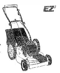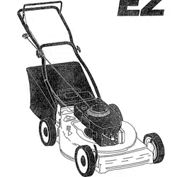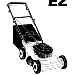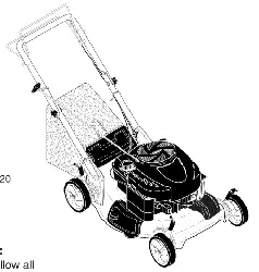

Owner's Manual
rRRFTSMAN"
6.0 HORSEPOWER
22" EZ MULCH
POWER PROPELLED
ROTARY LAWN MOWER
Model No.
917.387242
• Safety
• Assembly
• Operation
• Maintenance
• Espa_ol
• Repair Parts
CAUTION:
Read and follow all
Safety Rules and Instructions
before operating this equipment
Seam, Roebuck and Co., Hoffman Estates, IL 60179

Warranty :
2 Product Specifications 9
Safety Rules 2 Service and Adjustments 12
Assembly 4 Storage 13
Operation 5 Troubleshooting 14
Maintenance Schedule 8 Repair Parts 32
Maintenance 8 Parts Ordering Back Cover
LIMITED TWO YEAR WARRANTY ON CRAFTSMAN POWER MOWER
For two years from date of purchase, when this Craftsman Lawn Mower is maintained,
lubricated, and tuned up according to the operating and maintenance instructions in the
owner's manual, Sears will repair free of charge any defect in matedal or workmanship.
If this Craftsman Lawn Mower is used for commercial or rental purposes, this warranty
applies for on y 90 days from the date of purchase.
Th,s Warranty dOes not cover:
• Expendable itbms which become worn during normal use, such as rotary mower
blades, blade adapters, belts, air cleaners and spark plug.
• Repairs necessary because of operator abuse or negligence, including bent crank-
shafts and the failure to maintain the equipment according to the instructions con-
tained in the owner's manual.
Warranty service is available by retuming the Craftsman power mower to the nearest
Sears Service CenterlDepartment in the United States. This warranty applies only while
this product is in use in the United States.
This Warranty gives you specific legal rights, and you may also have other rights which
vary from state to state.
SEARS, ROEBUCK AND CO., D/817 WA, HOFFMAN ESTATES, ILLINOIS 60179
Safety standards require operator pres-
ence controls to minimize the dsk of injury.
Your unit is equipped with such controls.
Do not attempt to defeat the function of the
operator presence controls under any
circumstances.
TRAINING:
• Read this operator's manual carefully.
Become familiar with the controls and
know how to operate your mower
properly, Learn how to quickly stop
mower.
• Do not allow children to use your mower.
Never allow adults to use mower without
proper instructions.
• Keep the area of operation clear of all
persons, especially small children and
pets.
• Use mower only as the manufacturer
intended and as described in this manual.
• Do not operate mower if it has been
dropped or damaged in any manner.
Always have damage repaired before
using your mower.
• Do not use accessory attachments that
are not recommended by the manufac-
turer. Use of such attachments may be
hazardous.
• The blade tums when the engine is
running.
PREPARATION:
• Always thoroughly check the area to be
mowed and clear itof all stones, sticks,
wires, bones, and other foreign objects.
These objects will be thrown by the blade
and can cause severe injury.
• Always wear safety glasses or eye
shields when starting and while using
your mower.
• Dressproperly. Do not operate mower
when barefoot or wearing open sandals.
Wear only solid shoes with good traction
when mowing.
• Check fuel tank before starting engine.
Do not fill gas tank indoors, when the
engine is running or when the engine is
hot. Allow the engine to cool for several
minutes before filling the gas tank. Clean
off any spilled gasoline before starting the
engine.
• Always make wheel height adjustments
before starting your mower. Never
attempt to do this while the engine is
running.
• Mow only in daylight or good artificial
light.
OPERATION:
• Keep your eyes and mind on your mower
and the area being cut. Do not let other
interests distract you.
• Do not mow wet or slippery grass. Never
run while operating your mower. Always
be sure of your footing -- keep a firm
hold on the handles and walk.
• Do not put hands or feet near or under
rotating parts. Keep clear of the discharge
opening at all times.
• Always stop the engine whenever you
leave or are not using your mower, or
before crossing driveways, walks, roads,
and any gravel_covered areas.
• Never direct discharge of material toward
bystanders nor allow anyone near the
mower while you are operating it.
• Before cleaning, inspecting, or repairing
your mower, stop the engine and make
absolutely sure the blade and all moving
parts have stopped. Then disconnect the
spark plug wire and keep itaway from the
spark plug to prevent accidental starting.
• Do not continue to run your mower if you
hit a foreign object. Follow the procedure
outlined above, then repair any damage
before restarting and operating you
mower.
• Do not change the governor settings or
overspeed the engine. Engine damage or
personal injury may result.
• Do not operate your mower if it vibrates
abnormally. Excessive vibration is an
indication of damage; stop the engine,
safely check for the cause of vibration
and repair as required.
• Do not run the engine indoors. Exhaust
fumes are dangerous.
• Never cut grass by pulling the mower
towards you. Mow across the face of
slopes, never up and down or you might
lose your footing. Do not mow exces-
sively steep slopes. Use caution when
operating the mower on uneven terrain
or when changing directions -- maintain
good footing.
• Never operate your mowerwithout
proper guards, plates, grass catcher or
other safety devices in place.
MAINTENANCE AND STORAGE:
• Check the blade and the engine mount-
ing bolts often to be sure they are
tightened properly.
• Check all bolts, nuts and screws at
frequent intervals for proper tightness to
be sure mower is in safe working
condition.
• Keep all safety devices in place and
working.
• To reduce fire hazard, keep the engine
free of grass, leaves or excessive grease
and oil.
• Check grass catcher often for deteriora-
tion and wear and replace worn bags.
Use only replacement bags that are
recommended by and comply with
specifications of the manufacturer of your
mower.
• Always keep a sharp blade on your
mower.
• Allow engine to cool before stodng in any
enclosure.
• Never store mower with fuel in the tank
inside a building where fumes may reach
an open flame or an ignitionsource such
as a hot water heater, space heater,
clothes dryer, etc.
ACAUTION: Always disconnect spark
plug wire and place wire where it cannot
contact spark plug in order to prevent
accidental starting when setting up,
transporting, adjusting or making repairs.
WARNING
The engine exhaust from this product
contains chemicals known to the State of
California to cause cancer, birth defects,
or other reproductive harm.
3
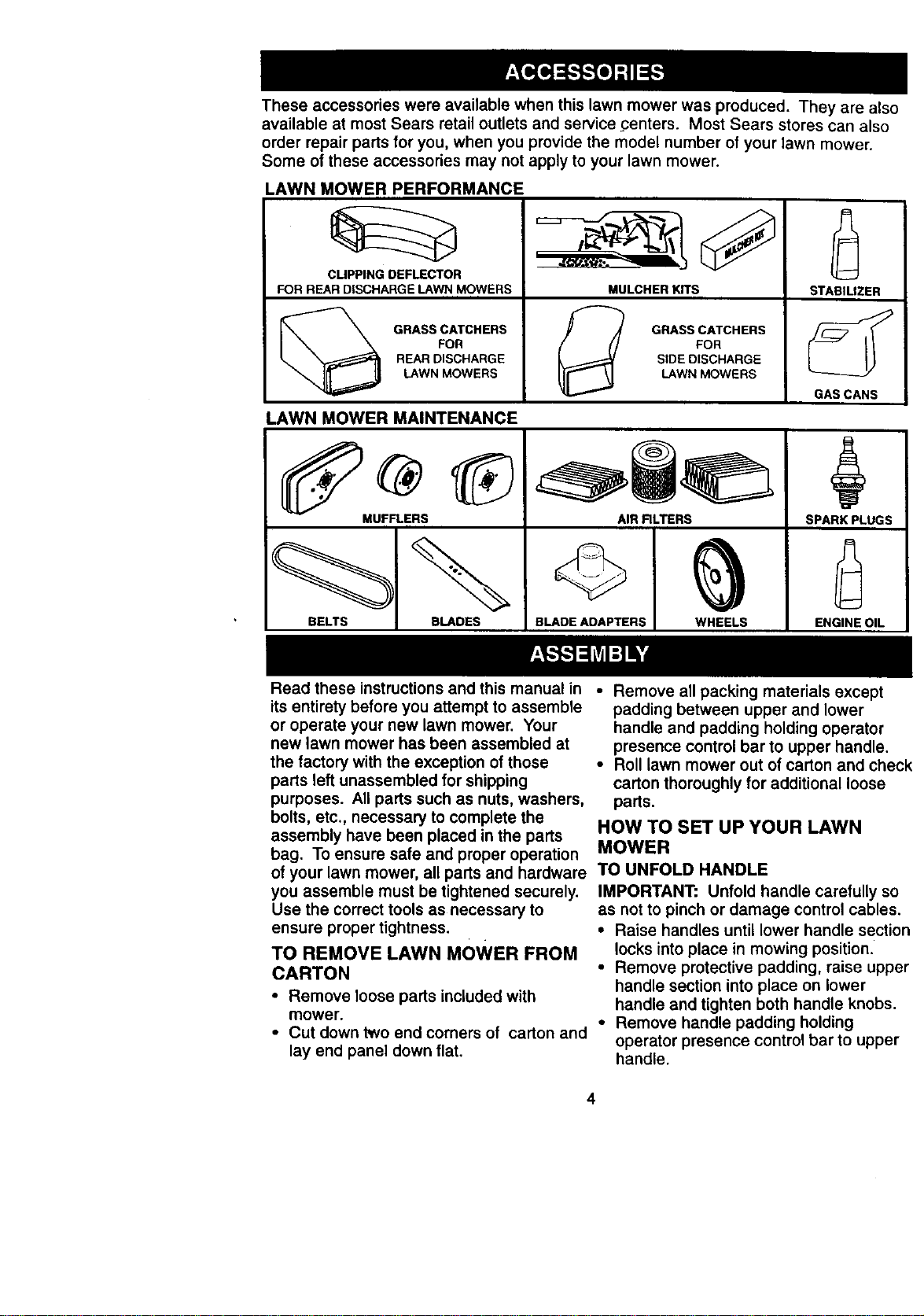
Theseaccessories were available when this lawn mower was produced. They are also
available at most Sears retail outlets and service _:enters. Most Sears stores can also
order repair parts for you, when you provide the model number of your lawn mower.
Some of these accessories may not apply to your lawn mower.
LAWN MOWER PERFORMANCE
' '
CLIPPING DEFLECTOR
FOR REAR DISCHARGE LAWN MOWERS MULCHER KITS
STABILIZER
GRASS CATCHERS _ GRASS CATCHERS
FOR FOR
REAR DISCHARGE SIDE DISCHARGE
LAWN MOWERS LAWN MOWERS
GAS CANS
LAWN MOWER MAINTENANCE
MUFFLERS AIR RLTERS SPARK PLUGS
BELTS BLADES BLADE ADAPTERS WHEELS ENGINE OIL
Read these instructions and this manual in • Remove all packing materials except
its entirety before you attempt to assemble
or operate your new lawn mower. Your
new lawn mower has been assembled at
the factory with the exception of those
parts left unassembled for shipping
purposes. All parts such as nuts, washers,
bolts, etc., necessary to complete the
assembly have been placed in the parts
bag. To ensure safe and proper operation MOWER
of your lawn mower, all parts and hardware TO UNFOLD HANDLE
you assemble must be tightened securely.
Use the correct tools as necessary to
ensure proper tightness.
TO REMOVE LAWN MOWER FROM
CARTON
• Remove loose parts included with
mower.
• Cut down two end corners of carton and
lay end panel down flat.
padding between upper and lower
handle and padding holding operator
presence control bar to upper handle.
• Roll lawn mower out of carton and check
carton thoroughly for additional loose
parts.
HOW TO SET UP YOUR LAWN
IMPORTANT: Unfold handle carefully so
as not to pinch or damage control cables.
• Raise handles until lower handle section
locks into place in mowing position.
• Remove protective padding, raise upper
handle section into place on lower
handle and tighten both handle knobs.
• Remove handle padding holding
operator presence control bar to upper
handle.
4
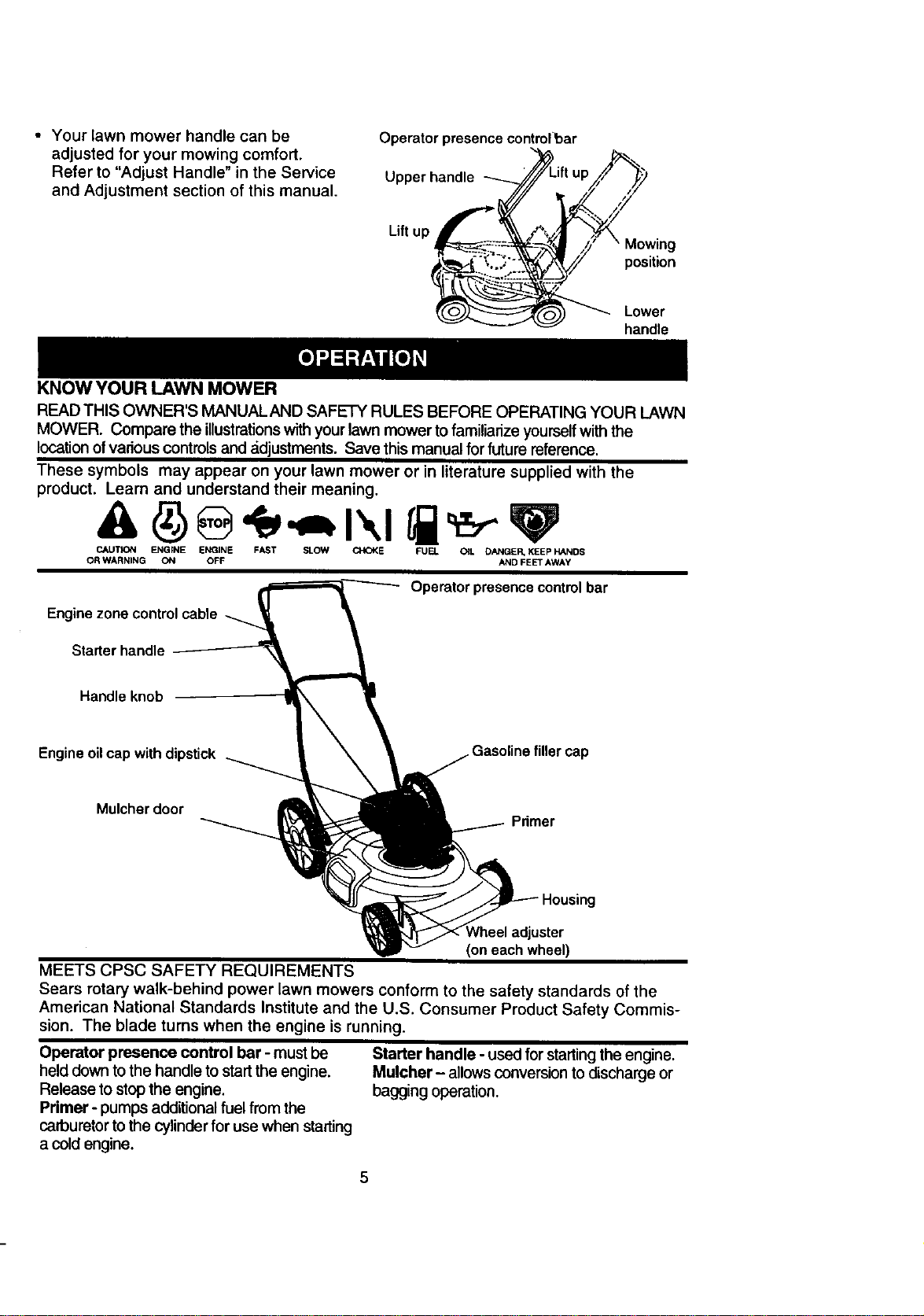
• Your lawn mower handle can be
adjusted for your mowing comfort.
Refer to "Adjust Handle" in the Service
and Adjustment section of this manual.
Operator presence control 1:)ar
_L _
' i '"
Upper handle ft up
Liftup \_Vj_
_-_--=-- Mowing
.._;;!;:.. position
Lower
handle
KNOW YOUR LAWN MOWER
READ THIS OWNER'S MANUALAND SAFETY RULES BEFORE OPERATING YOUR LAWN
MOWER. Compare the illustrations with your lawn mower to familiarize yourself with the
location of various controls and ._djustments. Save this manual for future reference.
These symbols may appear on your lawn mower or in literature supplied with the
product. Learn and understand their meaning.
CAUTION ENGINE ENGINE FAST SLOW CHOKE FUEL OIL DANGER, KEEP HANDS
OR WARNING ON OFF AND FEET AWAY
Operator presence control bar
Engine zone control cable
Starter handle
Handle knob
Engine oil cap with dipstick
filler cap
Mulcher door
Primer
Ig
adjuster
(on each wheel)
MEETS CPSC SAFETY REQUIREMENTS
Sears rotary walk-behind power lawn mowers conform to the safety standards of the
American National Standards Institute and the U.S. Consumer Product Safety Commis-
sion. The blade turns when the engine is running.
Operator presence control bar - must be
held down to the handle to startthe engine.
Release to stopthe engine.
Primer- pumps additionalfuel from the
carburetortothe cylinderfor use when starting
a coldengine.
Starter handle - used for startingthe engine.
Mulcher- allowsconversionto discharge or
bagging operation.
5
Theoperationof any lawn mower can resultin
foreign objectsthrown intothe eyes, which can
resultin severe eye damage. Always wear
safety glasses or eye shields while operating
yourlawn mower or performingany adjust-
ments or repairs. We recommend a wide
visionsafety mask over spectacles or standard
safety glasses.
HOW TO USE YOUR LAWN MOWER
ENGINE SPEED CONTROL
The engine speed was set at the factory
for optimum performance. Speed is not
adjustable.
ENGINE ZONE CONTROL
ACAUTION: Federal regulationsrequire an
engine controlto be installedon this lawn
mower in order to minimize the riskofblade
contact injury.Do not under any circumstances
attemptto defeat the function of the operator
control. The blade turnswhen the engine is
running.
• Your lawn mower isequipped with an
operatorpresence controlbar which
requiresthe operator to be pos_oned
behind the lawn mower handle to startand
operate the lawn mower.
TO ADJUST CUTTING HEIGHT
• Raise wheels for low cut and lower wheels
for highcut.
• Adjustcuttingheight to suityour require-
merits. Medium positionisbast for most
lawns.
• To change cutting height, squeeze adjuster
lever toward wheel. Move wheel up or
down to suityour requirements. Be sure all
wheels are in the same setting.
NOTE: Adjuster isproperly positionedwhen
plate tab insertsinto hole in lever. A/so, 9-
positionadjusters (if so equipped) allow lever
to be positionedbetween the plate tabs.
Lowerwheels for
high cut
Platetab
Raise wheels for low
cut
NOTE: Your lawn mower has been
shipped ready for mulching operation. To
convert to discharging operation, you must
install the discharge deflector attachment
included with your mower.
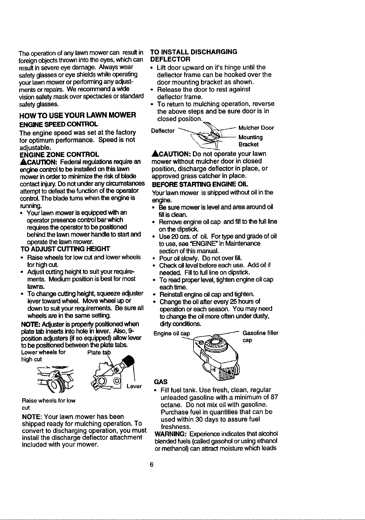
TO INSTALL DISCHARGING
DEFLECTOR
• Lift door upward on it's hinge until the
deflector frame can be hooked over the
door mounting bracket as shown.
• Release the door to rest against
deflector frame.
• To return to mulching operation, reverse
the above steps and be sure door is in
closed position.
_ .. "_-------- MulcherDoor
Deflector
\_ _--_J----_ Mounting
Bracket
ACAUTION: Do not operate your lawn
mower without mulcher door in closed
position, discharge deflector in place, or
approved grass catcher in place.
BEFORE STAFmNG ENGINE OIL
Yourlawn mower is shippedwithout oilin the
engine.
• Be sure mower is level and area around oil
fill isclean.
• Remove engine oilcap and till to the full line
on the dpstic_
• Use2Oozs.of oil. Fortype and grade of oil
to use, see "ENGINE" in Maintenance
sectionof this manual.
• Pouroilslowly. Do not ever fill.
• Check oillevel before each usa. Add oilif
needed. Fillto fulllineon dipstick.
• To read properlevel, tightenengine oilcap
each time.
• Reinstallengine oilcap and tighten.
• Change the oilafterevery 25 hours of
operation or each season. You may need
to change the oilmore often under dusty,
dirtyconditions.
Engine oil
GAS
Gasolinefiller
cap
• Fill fuel tank. Use fresh, clean, regular
unleaded gasoline with a minimum of 87
octane. Do not mix oil with gasoline.
Purchase fuel in quantities that can be
used within 30 days to assure fuel
freshness.
WARNING: Experience indicatesthat alcohol
blended fuels (calledgasehol or using ethanol
or methanol) can attractmoisture which leads
6
to separation and formation of acids during
storage. Acidic gas can damage the fuel
system of an engine while in storage. To avoid
engine problems, the fuel system should be
emptied before storage of 30 days or longer.
Drain the fuel tank, start the engine end let it
rununtil fuel lines and carburetor are empty.
Use fresh fuel next season. See Storage
Instructions for additional information. Never
use engine or carburetor cleaner products in
fuel tank or permanent damage may occur.
TO START ENGINE
• To start a cold engine, push primer five
(5) times before trying to start. Use a
firm push. This step is not usually
necessary when starting an engine
which has already run for a few minutes.
• Hold operator presence control bar
down to the handle and pull starter
handle quickly. Do not allow starter
rope to snap back.
• To stop engine, release operator
presence control bar.
NOTE: In cooler weather it may be
necessary to repeat priming steps. In
warmer weather over priming may cause
flooding and engine will not start. If you do
flood engine, wait a few minutes before
attempting to start and do not repeat
priming steps.
MOWING TIPS
• Under certain conditions, such as very
tall grass, it may be necessary to raise
the height of cut to reduce pushing effort
and to keep from overloading the engine
and leaving clumps of grass clippings. It
may also be necessary to reduce
ground speed and/or run the lawn
mower over the area a second time.
• For extremely heavy cutting, reduce the
width of cut by overlapping previously
cut path and mow slowly.
• For better grass bagging and most
cutting conditions, the engine speed
should be set in the fast position.
• For side discharge lawn mowers, cutting
in a counter-clockwise direction, starting
at the outside of the area to be cut,
spreads grass clippings more evenly
and puts less load on the engine. To
keep clippings off of walkways, flower
beds, etc., make the first cuts in a
clockwise direction.
• Pores in cloth grass catchers can
become filled with dirt and dust with use
and catchers will collect less grass. To
prevent this, regularly hose catcher off
with water and let dry before using.
• Keep top of engine around starter clear
and clean of grass clippings and chaff.
This will help engine air flow and extend
engine life.
MULCHING MOWING TiPS
IMPORTANT: Forbest gerformance, keep
mower housing free of built-up grass and
trash. See "Cleaning" in MAINTENANCE
section of this manual.
• The special mulching blade will reout the
grass clippingsmany times and reduce
them in size so that as they fall ontothe
lawn they willdisperse intothe grass and
not be noticed. Also,the mulched grass will
biodegrade quicklyto provide nutrientsfor
the lawn. Always mulchwith your highast
engine (blade) Speed as thiswill providethe
best recuttingactk)n of the blades.
• Avoid cuttingyour lawn when itiswet. Wet
grass tends toform dumps and interferes
with the mulching action. The best time to
mow your lawn isthe early afternoon. At
this time the grass has dried and the newly
cutarea will not be exposed to the direct
sun,
• For best results,adjustthe lawn mower
cutting height so that the lawn mower cuts
off only the top one-third of the grass blades.
Ifthe la.wn is overgrown it will be necessary
to raise the height ofcut to reduce pushing
effortand to keep from overloading the
engine and leaving clumps of mulched
grass. For extremely heavy mulching,
reduce your widthof cutby overlapping
previouslycutpath and mow slowly.
• Certain types of grass and grass conditions
may require that an area be mulched a
second time to completely hide the
clippings. When doing a second cut, mow
across or perpendicular to the first cut path.
• Change your cut_ng pattern from week to
week. Mow north to south one week then
change to east to west the next week. This
will help prevent matting and graining of the
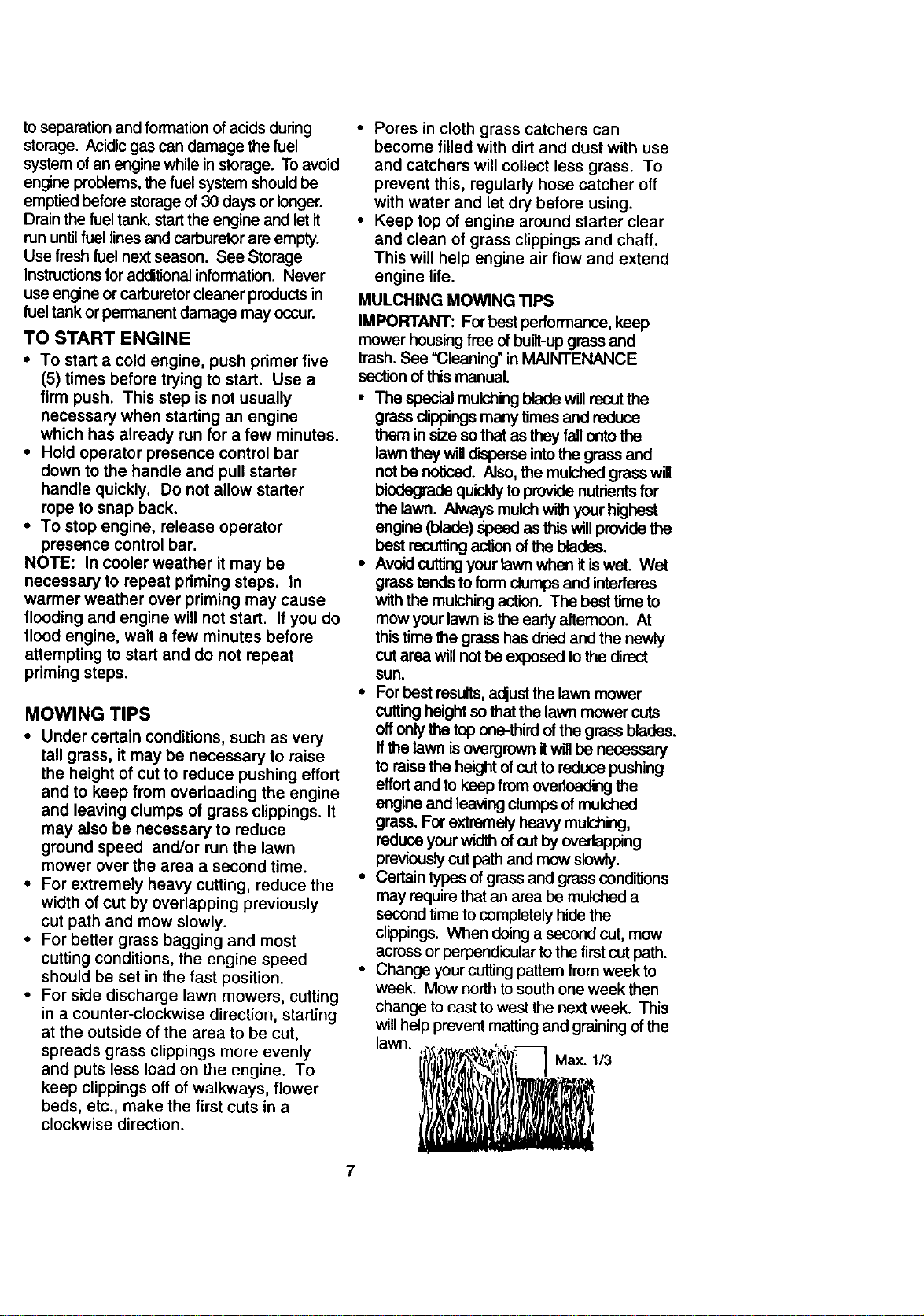
lawn. :t)_..l_t_.=_- _ Max 1/3
ll' li! 'lfAl lillL .L': ,
7
MAINTENANCE SCHEDULE
FILL IN DATES
AS YOU COMPLETE
REGULAR SERVICE
Check for LooseFasteners II/
Cleardlnspect Grass Catcher
If Equipped) ql/ _
M Clean Lawn Mower
O Clean Under Drive Cover
(Power-Propelled Mowers) _/'
Check drive belt/pulleys
E (Power-PropelledMowers} _1/
Check/S harpen/Fleplace Blade fl/s
Lubrication Chart _ ¥/
C_eanBattery/RecharQe
/Etectdc Start Mowers_ t/ If4
E: Check En_lineOil Level Ipa
N Change Er_jine Oil _/1:2
G clean Air Filter i/ 2
I Inspect Muffler _/_
N Clean or Replace Spark Plug
v"
E ReplaceAirFilterPaperCartridoe 1_2
SERVICE DATES
I - Change more often when operating under • heavy load or il high amb_nt temperatures.
2 - service more often when oper_ing in _r_ or dusty conditions,
3 - Replace blades more often when mowing In sandy soil.
4. Charge 48 hours I1 end of season.
GENERAL RECOMMENDATIONS
The warranty on this lawn mower does not
cover itemsthat have been subjected to
operator abuse or negligence. To receive full
value from the warranty, operator must
maintain mower as instructed in this manual.
Some adjustments will need to be made
periodically to properly maintain your unit.
All adjustments in the Service and Adjust-
ments section ofthis manual should be
checked at least once each season.
• Once a year, replace the spark plug, clean
or replace air filter element and check blade
for wear. A new spark plug and clean/new
air filter element assures proper air-fuel
mixture and helps your engine run better
and last longer.
• Follow the maintenance schedule in this
manual.
BEFORE EACH USE
• Check engine oillevel.
• Check for loose fasteners.
LUBRICATION
Keep unitwell lubricated(See "LUBRICATION
CHART").
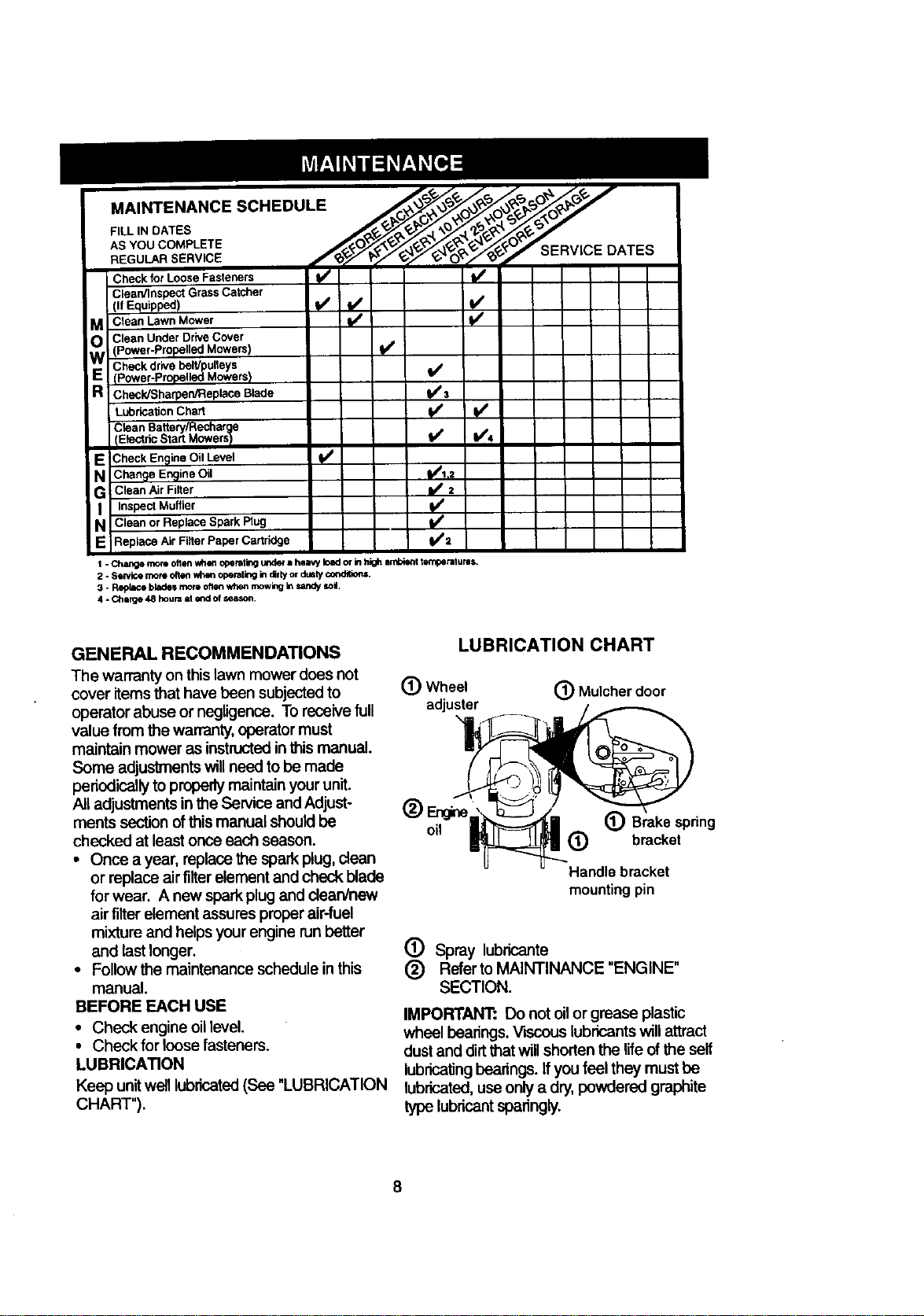
LUBRICATION CHART
(_ Wheel (_ Mulcher door
adjuster
(_) Brake spring
(_ bracket
Handle bracket
mountingpin
(_) Spray lubricante
(_) Referto MAINTINANCE "ENGINE"
SECTION.
IMPORTANT: Do not oil or grease plastic
wheal bearings. Viscous lubricantswill attract
dust and dirt that willshorten the life of the self
lubricating bearings. If you feel they must be
lubricated,use only a dry, powdered graphite
type lubricantsparingly.
8
PRODUCT SPECIFICATIONS
MODEL NUMBER 917.387242
SERIAL NUMBER
DATE OF PURCHASE
HORSEPOWER: 6.0
DISPLACEMENT: 11.5 CU. IN.
GASOLINE CAPACITY/TYPE: 1.5 QUARTS
UNLEADED REGULAR
OIL TYPE (API-SF/SG/SH): SAE 30 (ABOVE 32°F)
SAE 5W-30 (BELOW 32°F)
OIL CAPACITY: 20 OZS.
SPARK PLUG(GAP: .030") " CHAMPION RJ19LM OR J19LM
VALVECLEARANCE: INTAKE: .004 - .008
EXHAUST: .004- .008
SOLID STATE IGNITION
AIR GAP: .0125 IN.
BLADE BOLT TORQUE: 35-40 FT. LBS.
The model and serial numbers will be found on a decal attached to the rear of the
lawn mower housing.Record both serial number and date of purchase in space
provided above.
LAWN MOWER
• Remove blade and attaching hardware
Always observe safety ruleswhen performing
any maintenance.
TIRES
• Keep tires free of gasoline, oil, or insect
controlchemicals which can harm rubber.
• Avoid stumps,stones, deep ruts,sharp
objects and other hazards that may cause
tire damage.
BLADE CARE
For best results, mower blade must be
kept sharp. Replace bent or damaged
blades.
TO REMOVE BLADE
• Disconnect spark plug wire from spark
plug and place wire where it cannot
come in contact with spark plug.
• Turn lawn mower on its side. Make sure
air filter and carburetor are up.
• Use a wood block between blade and
mower housing to prevent blade from
turning when removing blade bolt.
• Protect your hands with gloves and/or
wrap blade with heavy cloth.
• Remove blade bolt by turning counter-
clockwise.
(bolt, lock washer and hardened
washer).
NOTE: Remove the blade adapter and
check the key inside hub of blade adapter.
The key must be in good condition to work
properly. Replace adapter if damaged.
TO REPLACE BLADE
• Position the blade adapter on the engine
crankshaft. Be sure key in adapter and
crankshaft keyway are aligned.
• Position blade on the blade adapter
aligning the two (2) holes in the blade
with the raised lugs on the adapter.
• Be sure the trailing edge of blade
(opposite sharp edge) is up toward the
engine.
• Install the blade bolt with the lock
washer and hardened washer into blade
adapter and crankshaft.
• Use block of wood between blade and
lawn mower housing and tighten the
blade bolt, turning clockwise.
The recommended tightening torque is
35-40 ft. Ibs.
9
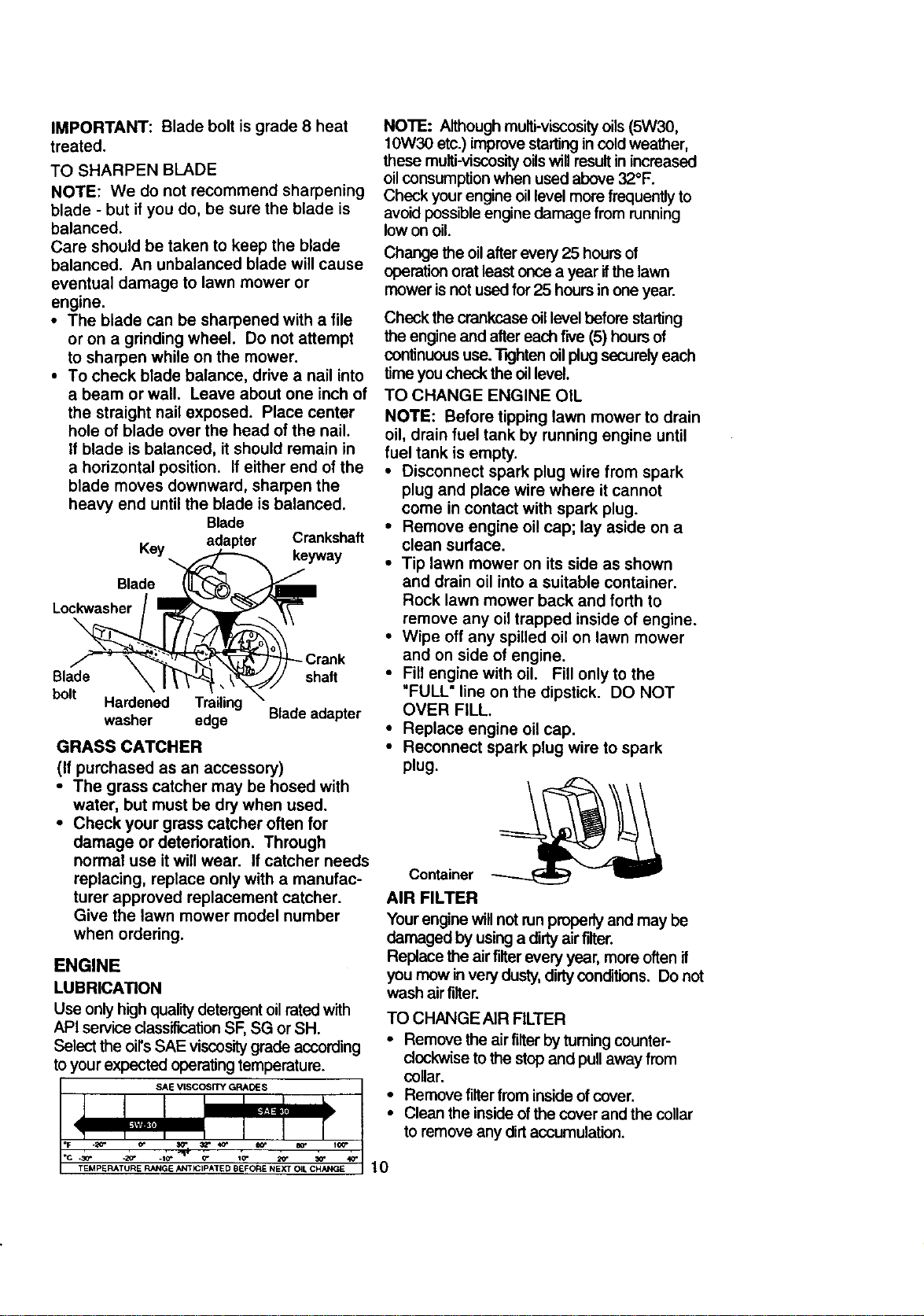
IMPORTANT: Blade bolt is grade 8 heat
treated.
TO SHARPEN BLADE
NOTE: We do not recommend sharpening
blade - but if you do, be sure the blade is
balanced.
Care should be taken to keep the blade
balanced. An unbalanced blade will cause
eventual damage to lawn mower or
engine.
• The blade can be sharpened with a file
or on a grinding wheel. Do not attempt
to sharpen while on the mower.
• To check blade balance, drive a nail into
a beam or wall. Leave about one inch of
the straight nail exposed. Place center
hole of blade over the head of the nail.
If blade is balanced, it should remain in
a horizontal position. If either end of the
blade moves downward, sharpen the
heavy end until the blade is balanced.
Blade
Key adapter Crankshaft
keyway
Blade
Lockwasher
\
Blade shaft
bolt
Hardened Trailing
washer edge Bladeadapter
GRASS CATCHER
(If purchased as an accessory)
• The grass catcher may be hosed with
water, but must be dry when used.
• Check your grass catcher often for
damage or deterioration. Through
normal use it will wear. If catcher needs
replacing, replace only with a manufac-
turer approved replacement catcher.
Give the lawn mower model number
when ordering.
ENGINE
LUBRICATION
Use onlyhigh quality detergent oilrated with
API service classificationSF, SG or SH.
Select the oirs SAE viscositygrade according
to your expected operating temperature.
SAE VISCOSITY GRADES
T_MPERATURE RANGE ANTICIPATED eEFORE NEXT OIL C_°'ANGE
NOTE: Although muifi-viscosityoils(5W30,
10W30 etc.) improve startingin coldweather,
these multi-viscosityoilswillresultin increased
oilconsumptionwhen used above 32°F.
Check your engine oil level more frequently to
avoid possibleengine damage from running
low on oil.
Change the oil after every 25 hours of
operation orat least once a year ifthe lawn
mower is not used for 25 hours in one year.
Check the crankcase oillevel before starting
the engine and after each frye (5) hours of
continuous use. TKJhtenoilplug securely each
time you check the oil level.
TO CHANGE ENGINE OIL
NOTE: Before tipping lawn mower to drain
oil, drain fuel tank by running engine until
fuel tank is empty.
• Disconnect spark plug wire from spark
plug and place wire where it cannot
come in contact with spark plug.
• Remove engine oil cap; lay aside on a
clean surface.
• Tip lawn mower on its side as shown
and drain oil into a suitable container.
Rock lawn mower back and forth to
remove any oil trapped inside of engine.
• Wipe off any spilled oil on lawn mower
and on side of engine.
• Fill engine with oil. Fill only to the
"FULL" line on the dipstick. DO NOT
OVER FILL.
• Replace engine oil cap.
• Reconnect spark plug wire to spark
plug.
Container
AIR FILTER
Your engine will not runproperly and may be
damaged by usinga dirty air filter.
Replace the air filterevery year, more often if
you mow invery dusty,dirtyconditions. Do not
wash air filter.
TO CHANGE AIR FILTER
• Remove the air filter by tuming counter-
clockwise to the stop and pull away from
collar.
• Remove filter from inside of cover.
• Clean the inside of the cover and the collar
to remove any dirt accumulation.
10
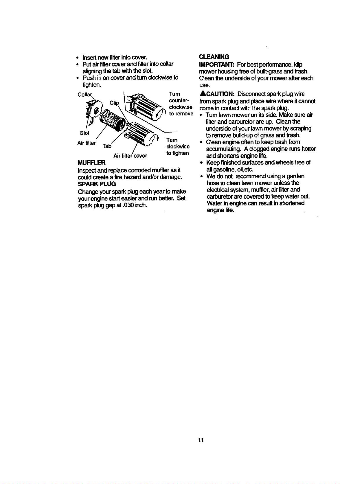
• Insert new filterintocover.
• Put airfllter cover and filterintocellar
aligningthetabwiththeslot.
• Push inon coverand tum clockwiseto
tighten.
Turn
counter-
dockwise
to remove
Slot
Tum
Airfilter Tab clockwise
Airfiltercover to tighten
MUFFLER
Inspectand replace corroded muffleras it
could create a tire hazard and/or damage.
SPARK PLUG
Change yourspark plug each year to make
yourengine starteasier and nJnbetter. Set
spark pluggap at .030 inch.
CLEANING
IMPORTANT" For best performance, kiip
mower housing free of built-grossand trash.
Clean the underside ofyour mower after each
use.
ACAUTION: Disconnect spark plug wire
from spark plug and place wire where itcannot
come in centact with the spark plug.
• Turn lawn mower on itsside. Make sure air
filter and carburetor are up. Clean the
underside of your lawn mower by scraping
to remove build-upof grass and trash.
• Clean engine often to keep trashfrom
accumulating. A dogged engine nJnshotter
and shortens engine life.
• Keep finished surfaces and wheels free of
all gasoline, oil,etc.
• We do not recommend usinga garden
hose to clean lawn mower unlessthe
electricalsystem, muffler, air filterand
carburetor are covered to keep water out.
Water in engine can resultin shortened
engine life.
11
,LiLCAUTION: Before performing any
service and adjustments:
• Release control bar and stop engine.
• Make sure the blade and all moving
parts have completely stopped.
• Disconnect spark plug wire from spark
plug and place where it cannot come
in contact with plug.
LAWN MOWER
TO ADJUST CUTTING HEIGHT
See "TO ADJUST CUTTING HEIGHT" in
the Operation section of this manual.
REAR DEFLECTOR
The rear deflector, attached between the
rear wheels of your mower, is provided to
minimize the possibility that objects will be
thrown out of the rear of the mower into
the operator's mowing position. If the
deflector becomes damaged, it should be
replaced.
DISCHARGE GUARD
The discharge guard, attached to the
discharge opening of your lawn mower, is
provided to prevent the possibility of injury
resulting from objects being thrown out of
the discharge opening into the operator
mowing position. If the discharge guard
becomes damaged, it should be replaced.
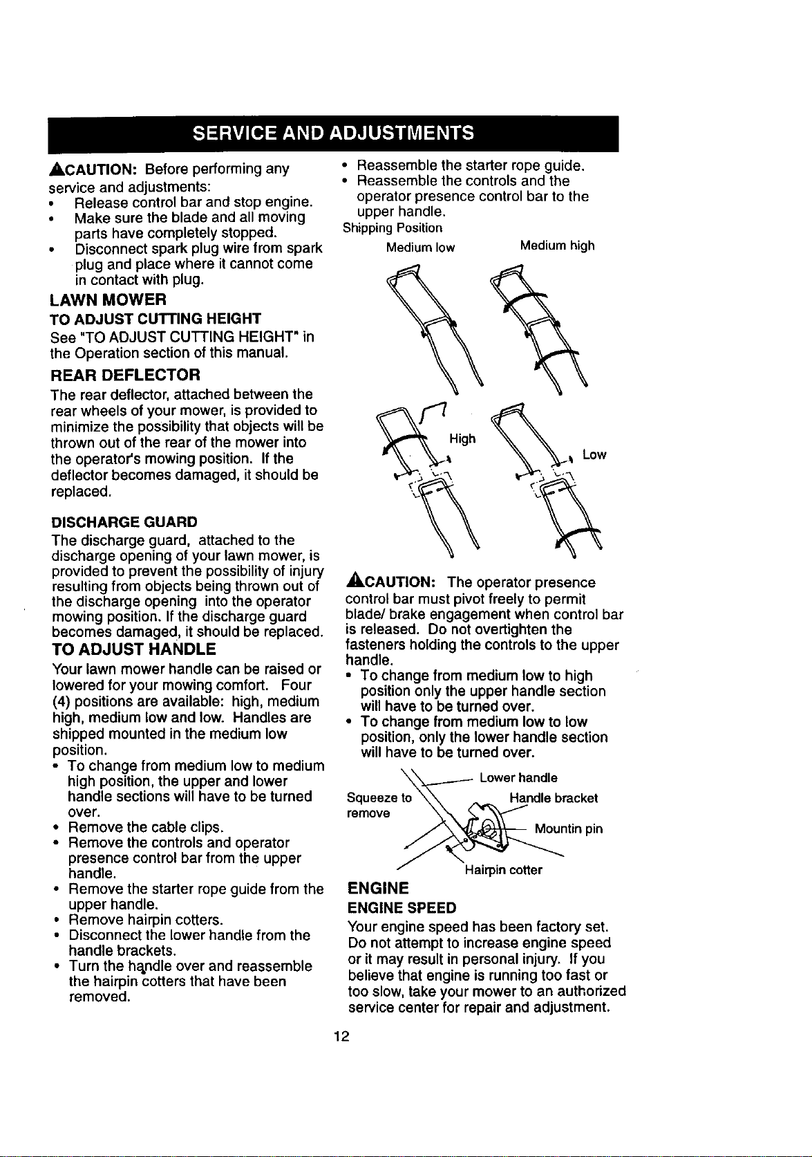
TO ADJUST HANDLE
Your lawn mower handle can be raised or
lowered for your mowing comfort. Four
(4) positions are available: high, medium
high, medium low and low. Handles are
shipped mounted in the medium low
position.
• To change from medium low to medium
high position, the upper and lower
handle sections will have to be turned
over.
• Remove the cable clips.
• Remove the controls and operator
presence control bar from the upper
handle.
• Remove the starter rope guide from the
upper handle.
• Remove hairpin cotters.
• Disconnect the lower handle from the
handle brackets.
• Turn the handle over and reassemble
the hairpin cotters that have been
removed.
• Reassemble the starter rope guide.
• Reassemble the controls and the
operator presence control bar to the
upper handle.
Shipping Position
Medium low Medium high
High
Low
_.CAUTION: The operator presence
control bar must pivot freely to permit
blade/brake engagement when control bar
is released. Do not overtighten the
fasteners holding the controls to the upper
handle.
• To change from medium low to high
position only the upper handle section
will have to be turned over.
• To change from medium low to low
position, only the lower handle section
will have to be turned over.
remove
Lowerhandle
Handle bracket
Mountin pin
Hairpin cotter
ENGINE
ENGINE SPEED
Your engine speed has been factory set.
Do not attempt to increase engine speed
or it may result in personal injury. If you
believe that engine is running too fast or
too slow, take your mower to an authorized
service center for repair and adjustment.
12
CARBURETOR
Yourcarburetorhasanon-adjustable fixed
main jet for mixture control. If your engine
does not operate properly due to sus-
pected carburetor problems, take your
lawn mower to an authorized service
center for repair and/or adjustment.
IMPORTANT: Never tamper with the
engine governor, which is factory set for
the proper engine speed. Overspeeding
the engine above the factory high speed
scan be dangerous. If you think the
engine-governed high speed needs
adjusting, contact your nearest authorized
service center, which has proper equip-
ment and experience to make any
necessary adjustments.
Immediately prepare your lawn mower for
storage at the end of the season or ifthe unit
will not be used for 30 days or more.
LAWN MOWER
When lawn mower is to be storecl for a pedod
of time, clean itthoroughly, remove all dirt,
grease, leaves, etc. Store in a clean, dry area.
• Clean entire lawn mower (See "CLEANING"
in the Maintenance section of this manual).
• Lubricate as shown in the Maintenance
section of this manual.
• Be sure that all nuts, bolts, screws, and pins
are securely fastened. Inspect moving
parts for damage, breakage and wear.
Replace ifnecessary.
• Touch up all rusted or chipped paint
surfaces; sand lightly before painting.
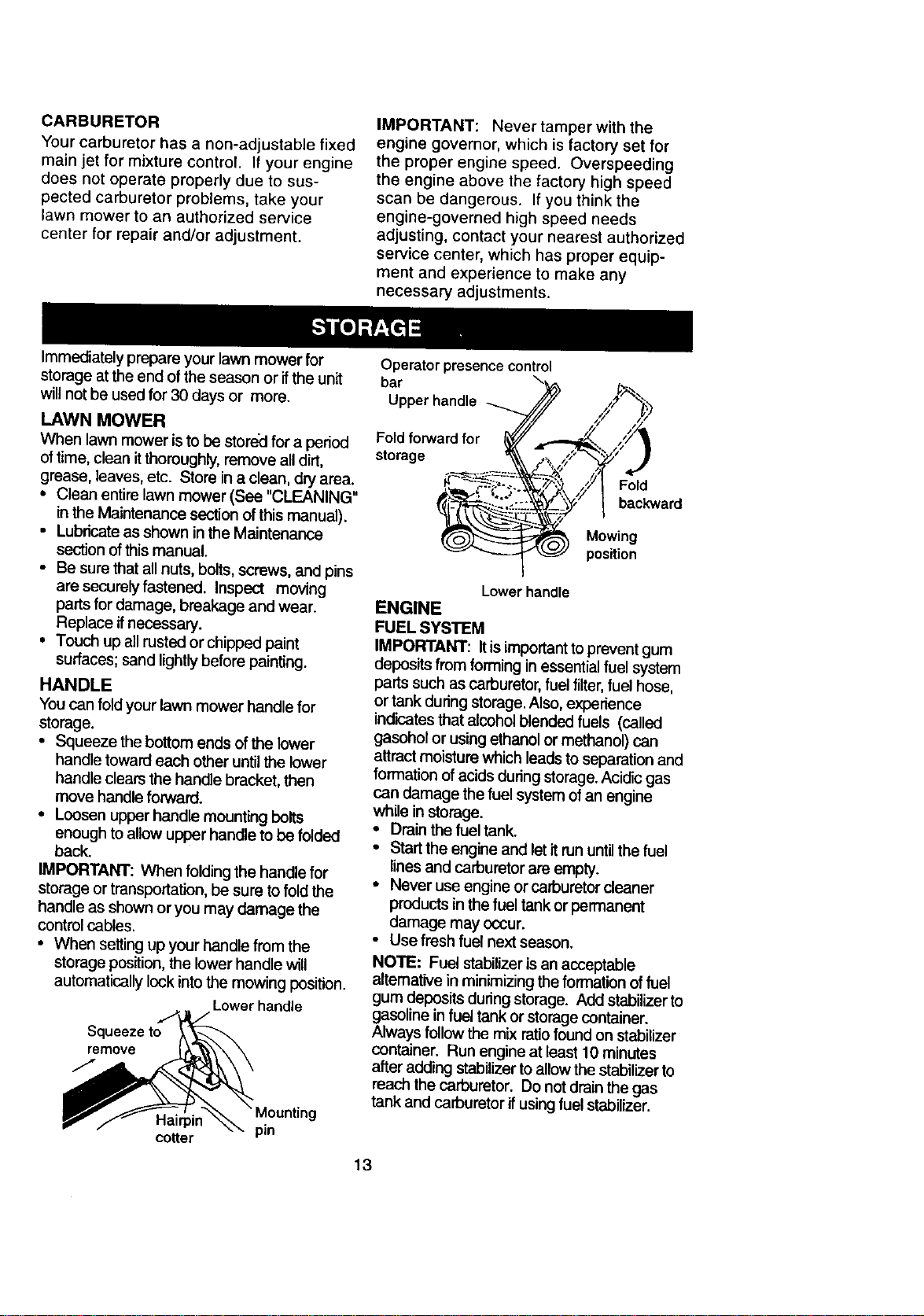
HANDLE
You can fold your lawn mower handle for
storage.
• Squeeze the bottom ends of the lower
handle toward each other until the lower
handle clears the handle bracket, then
move handle forward.
• Loosen upper handle mounting belts
enoughto allow upper handle tobe folded
back.
IMPORTANT: When foldingthe handle for
storage or transportation, be sure tofoldthe
handle as shown or you may damage the
control cables.
• When setting up your handle from the
storage position, the lower handle will
automatically lock into the mowing position.
Lower handle
Squeeze to
remove
j,
g
Hairpin pin
cotter
Operator presence control
bar
Upper handle
Fold fon_ard for _,,
storage _
,,_/I Fold
_"/ I backward
Mowing
position
Lower handle
ENGINE
FUEL SYSTEM
IMPORTANT: Itisimportant to prevent gum
depositsfrom forming in essentialfuel system
parts such as carburetor, fuel filter, fuel hose,
or tank during storage.Also, experience
indicatesthat alcohol blended fuels (called
gasohol or using ethanol or methanol) can
attract moisture which leads to separation and
formation of acids during storage. Acidic gas
can damage the fuel system of an engine
while in storage.
• Drain the fuel tank.
• Start the engine and let it run until the fuel
lines and carburetor are empty.
• Never use engine or carburetor cleaner
products in the fuel tank or permanent
damage may occur.
• Use fresh fuel next season.
NOTE: Fuel stabilizer is an acceptable
alternative in minimizing the formation of fuel
gum deposits during storage. Add stabilizerto
gasoline in fuel tank or storage container.
Always follow the mix ratio found on stabilizer
container. Run engine at least 10 minutes
alter adding stabilizer to allow the stabilizer to
reach the carburetor. Do not drain the gas
tank and carburetor if using fuel stabilizer.
13
ENGINE OIL
Drain oil (with engine warm) and replace with
clean engine oil. (See "ENGINE" in the
Maintenance section of this manual).
CYMNDER
• Remove spark plug.
• Pour one ounce (29 ml) of oil through spark
plug hole into cylinder.
• Pull starter handle slowly a few times to
distribute oil.
• Replace with new spark plug.
OTHER
• Do not store gasolinefrom one season to
another.
• Replace your gasolinecen ifyour can starts
to rust. Rust and/or dirtin your gasolinewill
cause problems.
• If possible,store your unitindoorsand cover
ittogive protectionfrom dust and dirt.
• Cover yourunitwith a suitable protective
cover that does not retainmoisture. Do not
use plastic. Plastic cannot breathe which
allowscondensation toform and willcause
your unitto rust.
IMPORTANT: Never cover mower while
engine and exhaust areas are still warm.
ACAUTION: Never store the lawn
mower with gasoline in the tank inside a
building where fumes may reach an open
flame or spark. Allow the engine to cool
before storing in any enclosure.
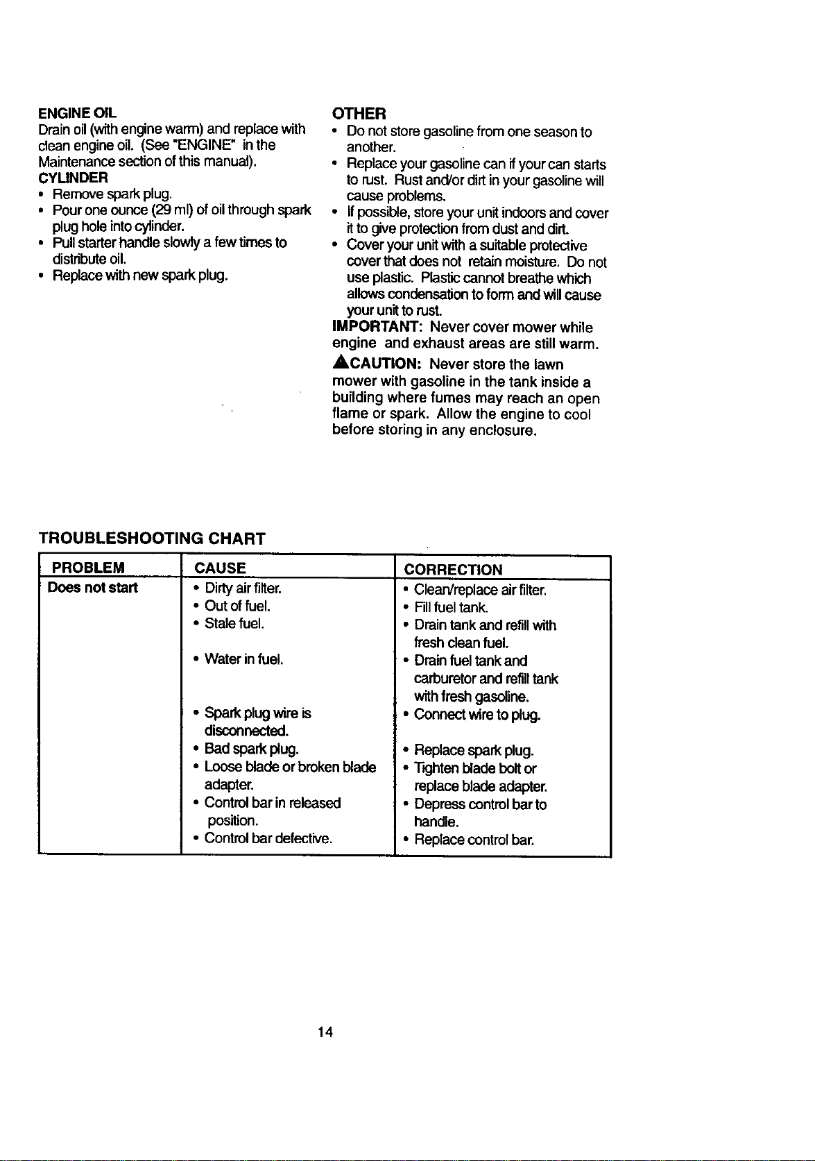
TROUBLESHOOTING CHART
PROBLEM
Does not start
CAUSE
• Dirty air filter.
• Out offuel.
• Stale fuel.
• Water in fuel.
• Spark plugwire is
disconnected.
• Bad spark plug.
• Loose blade or broken blade
adapter.
• Control bar in released
position.
• Control bar defective.
CORRECTION
• Clean/replace air fiiter.
• Fillfuel tank.
• Drain tank and refillwith
fresh clean fuel.
• Drain fuel tank and
carburetor and refilltank
with fresh gasoline.
• Connect wire to plug.
• Replace spark plug.
• "T'_jhtenblade boltor
replace blade adapter.
• Depress controlbar to
handle.
• Replace control bar.
14
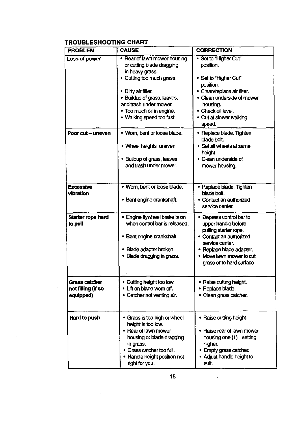
PROBLEM
Loseofpower
TROUBLESHOOTING CHART
CAUSE
• Rearoflawnmowerhousing
or cutting blade dragging
in heavy grass.
• Cutting too much grass.
Poor cut- uneven
Excessive
vibration
Starter rope hard
to pull
Grass catcher
not filling ('dso
equipped)
Hardtopush
• Dirtyair filter.
• Buildupof grass, leaves,
and trash under mower.
• Too much oilin engine.
• Walking speed too fast.
•Wom, bent or looseblade
• Wheel heights uneven
• Buildupofgrass leaves
and trash under mower
•Wom, bent or loose blade.
• Bent engine crankshaft.
• Engine flywheel brake ison
when controlbar isreleased
• Bent engine crankshafL
• Blade adapter broken
• Blade dragging ingrass.
• Cuttingheighttoo low.
• Uft on bladeworn off.
• Catcher notventingair.
• Grass istoo highor wheel
heightistoo low
• Rearof lawn mower
housingor blade dragging
in grass
• Grass catcher toofull
• Handle height posiltonnot
rightfor you
CORRECTION
• Set to "Higher Cut"
position.
• Set to "Higher Cut"
position
• Clean/replace air filter.
• Clean underside of mower
housing
• Check oil level
• Cut at slowerwalldng
speed
• Replace blade TKjhten
blade bolt.
• Set all wheels at same
height
• Clean underside of
mower housing
• Replace blade. T_hten
blade bolt
• Contact an authorized
service center.
• Depress controlbarto
upper handle before
pullingstarter rope.
• Contact an authorized
senlice center.
• Replace blade adapter.
• Move lawn mower tocut
grass or to hard surface
• Raise cuttingheight
• Replace blade
• Clean grass catcher.
-Raisecuttingheight
• Raise rear oflawn mower
housing one (1) setting
higher
• Empty grass catcher
• Adjust handle height to
suit
15
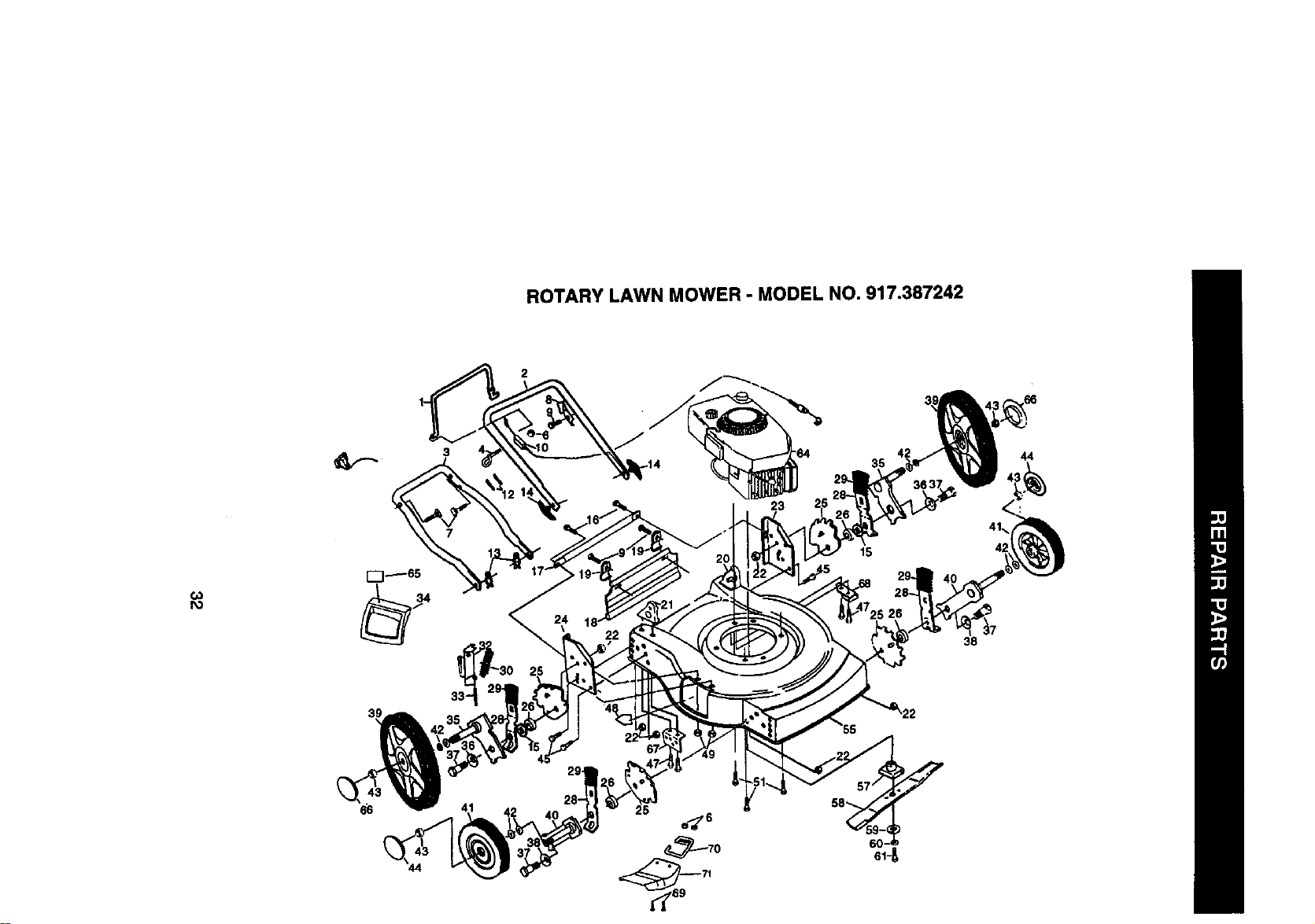
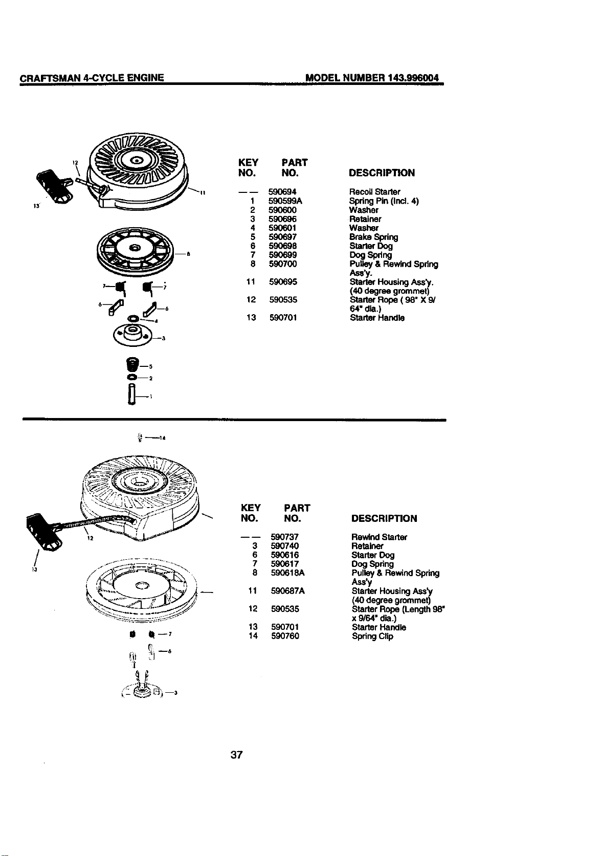
ROTARY LAWN MOWER - MODEL NO. 917.387242
2
3 42
35
44
23
(,O
1"--1_65
66 25
ROTARY LAWN MOWER - MODEL NO. 917.387242
o_
KEY PART
NO. NO
1 86902
2 165451X479
3 157081X479
4 153638
6 63601
7 131959
8 850733X004
9 750097
10 156577
12 66426
13 51793
14 136376
15 88348
16 S'rD512,505
17 165175)(479
18 140540
19 87584X004
20 151667x479
21 151665x479
22 75159_
23 700168X479
24 700166X479
25 750085X007
26 146630
28 700_31X004
29 701037
30 152124
32 154132
33 147286
34 151889
35 750913X004
36 61651
37 142748
38 62335
39 151138
40 145935X004
DESCRIPTION
Con_'olBar
Upper Handb
LowerHandle
RopeGuide
Locknut1/4-20
HandleBolt
Up-_ Bracket
Hex"n_eadRollingScrew #1024 x 3/4
EngineZone Con_ Cabla
Wire Tie
Hahn Cot_
HandleKnob
Flat Waster 3t8
Hex Head SelfTappingScrew 1/4-20 x 1/2
supputRod
Rear Delbctor
DellectorBracket
HandleBrad_t Assembly(Left)
HandlaBracket_ (Right)
Locknut3/8-16
SuppedBrad_t(Left)
supportBrack_(PJght)
Whe_ AdjusterBracket
Spacer
Bak_erSpnng
,Ba_ctorKnob
To.ion Spdng
Hou_ngBrack_As,_mb_,
HingeRod
DischargeGuard
A_e ArmA_emb_ (Rear)
sp_ngWasher(Rear)
Shoulde(Bolt3/8-16
BellavUlaWasher
Wheel& "nreAssembly(Rear)
A_eAtrnA._en'_y
KEY PART
NO. NO
DESCRIPTION
41 150348
42 57143
43 83gP.3
44 150182
45 74760612
47 149741
48 85463
49 STD541425
51 150406
55
57 851514
58 152202
59 851074
60 850_o3
61 851084
64 -.o.°-
66 151440
67 153350x479
68 153282x479
69 74180410
70 751399
71 752118
- - 161058
-- 166494
Whe_&"nreA._emUy(Front)
Wave Washer
Locknut 3/8-16
Hubcap
Hex Head Bolt 3/8-16 x 3/4
Screw 5/16-18 x3/4
Danger Decal
Locknut 1/4-20
Hex HeadThread RollingScrew 3/8-16 x1
LawnMov,_rHousing (Incl.Ref. #20, 47, 48, 53,
_4)
BladeAdapter
22"Blade
Washer
HelicalHardenedLockwasher3/8
Hex Head MachineSerew 3/8-24 x 1/4 Grd.8
Engine- (See Bmakdewn) Craftsman
Mod_ 143.996004
Hubcap
BracketSupportHa,-de (Right)
BracketSupportHandle(Left)
Screw
Bracket
Clipping Deflector
WarolngDec_
O_s Man_ (Eng--)
Availableaccassodasnot includedwithlawnmower:..
71 33072 GrassCatcher
71 33201 MulcherKit
71 33623 GasCan(2.SgaL)
71 33500 FuelStabilizer
71 33000 _6,E_W Oil(20oz.)
71 33316 MowerCover
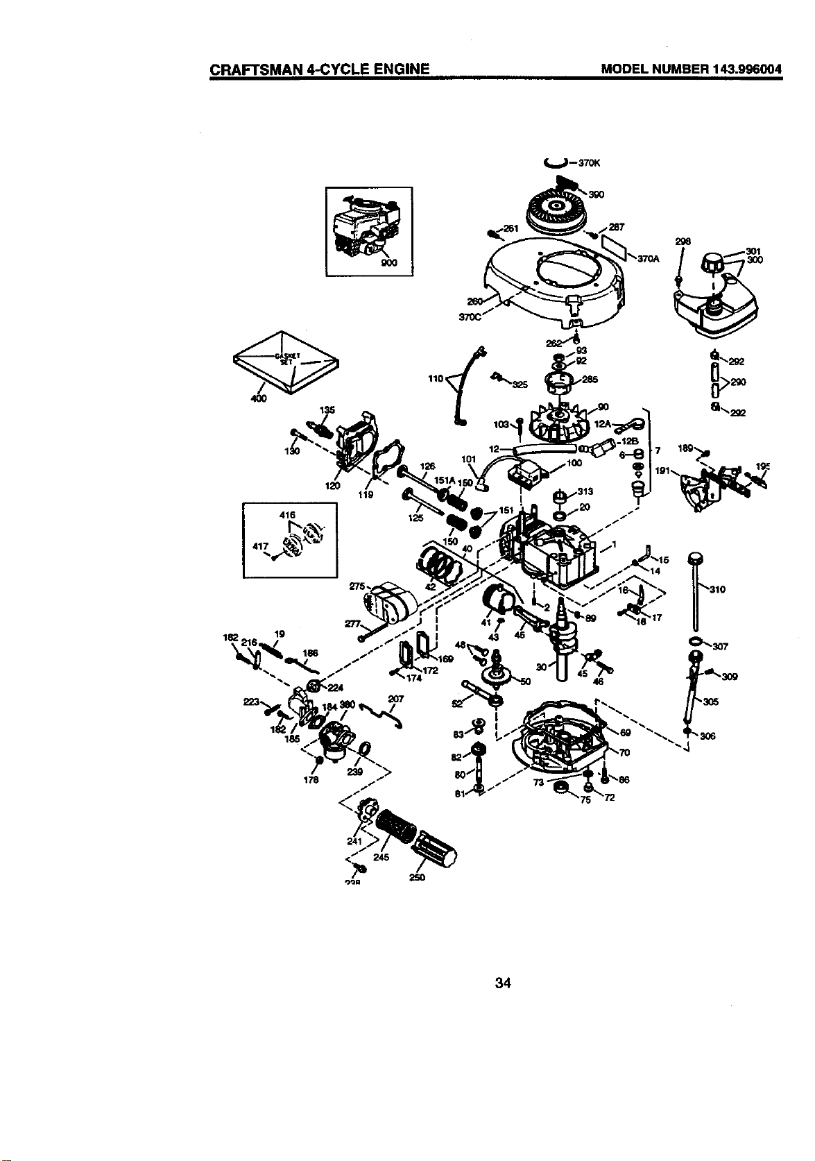
CRAFTSMAN 4-CYCLE ENGINE MODEL NUMBER 143.996004
4OO
135
120
11g
I 416
275,
182, lg
_261
126
2;16
1301
34
CRAFTSMAN 4-CYCLE ENGINE MODEL NUMBER 143.996004
KEY PART
NO. NO. DESCRIPTION
1 37266
2 26727
6 33734
7 36557
12 36775
12A 36558
12B 36694
14 28277
15 30589
16 34839A
17 31335
18 651018
19 36281
20 32600
30 36776
40 40004
4OOO5
41 36070
36071
42 4O0O6
42 40007
43 20381
45 36777
46 32610A
48 27241
50 36778
52 29914
69 35261
70 34311E
72 30572
73 28833
75 27897
80 30574A
81 30590A
82 30591
83 30588A
86 65O488
89 611004
90 611112
92 650815
93 650816
100 34443B
101 610118
103 651007
110 37047
119 36787
120 36825
125 37288
126 37289
130 6021A
135 35395
150 31672
151 31673
151A 40017
KEY
NO.
PART
NO.
Cylinder 169 36783
(Incl. 2,20 & 150) 172 36784
Dowel Pin 174 30200
Breather Element 178 29752
Breather Ass'y.
(Incl. 6 & 12A) 182 6201
Breather Tube 184 26756
Breather Cover & Tube
(Ind. 12B) 185 36785
Breather Tube Elbow 186 326.53
Washer 189 650839
Govemor Rod (Incl. 14) 191 36559A
Governor Lever
Governor Lever Clamp 195 610973
Sorew, Torx T-15, 207 34336
8-32 x 19/64" 216 33086
Extension Spdng 223 650451
Oil Seal 224 36786
Crankshaft 238 650932
Piston, Pin & Ring Set 239 34338
(Std.) 241 35797
Piston, Pin & Ring Set 245 35066
(.010" OS) 250 35065
Piston & Pin Aas'y. (Std.) 260 36980
(incl.43) 261 30200
Piston& PinAss'y. 262 650831
(.010" OS) 275 36790A
(Ind.43) 277 650988
Ring Set (Std.) 285 35000A
Ring Set (.010" OS) 287 650926
Piston Pin Retaining 290 29774
Ring 292 26460
Connecting Rod Ass'y. 298 28763
(ind. 46) 300 36916
Connecting Rod Bolt
Valve Lifter 301 36246
Camshaft (MCR) 305 35647
Oil Pump Ase'y. 306 36996
* Mounting Flange Gasket 307 35499
Mounting Flange (Incl. 72 309 650562
ttwu83,306) 310 35648
Oil Drain Plug (Ind. 73) 313 34080
Drain Plug Gasket 325 37152
Oil Seal 370A 36261
Govemor Shaft 370C 37199
Washer 370K 36695
Governor Gear Ass'y. 380 640174
(Ind. 81) 390 590737
Govemm Spool 400 36792B
Screw, I/4-20 x 1-1/4"
Flywheel Key 416 36085
Flywheel
Bolleville Washer 417 650821
Flywheel Nut
Solid State Ignition 900 -- --
Spark Plug Cover
Screw, Torx T-15, 900 ----
10-24 x 15/16"
Ground Wire
• Cylinder Head Gaske -- --
Cylinder Head
Exhaust Valve (Std.)
(ind. 151)
Intake Valve (Std.)
(ind. 151)
Screw, 5/16-18 x 1-1/2"
Resistor Spark Plug
(FU19LM)
Valve Spring
Valve Spring Cap
Intake Valve Seal 35
DESCRIPTION
• Valve Cover Gasket
Valve Cover
Screw, 10-24 x 9/16"
Nut & LockWasher,
1/4-28
Screw, 1/4-28 x 7/8"
* Carburetor To Intake
Pipe Gasket
Intake Pipe
Governor Link
Screw, 114-20 x 9/8"
S.E. Brake Bracket
(Ind. 195)
Terminal
Throttle Link
R.P.M. Adju_ng Lever
Screw, 1/4-20 x 1"
• Intake Pipe Gasket
Screw, 10-32 x 49/64"
• Air Cleaner Gasket
Air Cleaner Collar
Air Cleaner Filter
Air Cleaner Cover
Blower Housing
Screw, 10-24 x 9/16"
Screw, 1/4-20 x 1/2"
Muffler
Screw, 1/4-20 x 2-5/16"
Starter Cup
Screw, 8-32 x 21164"
Fuel Line
Fuel Line Clamp
Screw, 10-32 x 35/64"
Fuel Tank
(Ind. 292 & 301)
Fuel Cap
Oil Fill Tube
* "O"-Ring
"O"oRing
Screw, 10-32 x 1/2"
Dipstick
Spacer
Sp ngclk)
Lubrica_on Decal
Primer Decal
Starter Decal
Carburetor (IncL 184)
Rewind Starter
Gasket Set (ind. Items
Marked *)
Spark Arrestor Kit (Ind.
417)(Optional)
Screw, 10-32 x 1/2"
(Optional)
Replacement Engine
NONE
Replacement S/B
750796A, order from71-
999
RPM High 2900 to 3200
NOTE: This engine could have been builtwith 590694
starter
NOTE: All component dimensions given in U.S. inches
1 inch = 25.4 mm
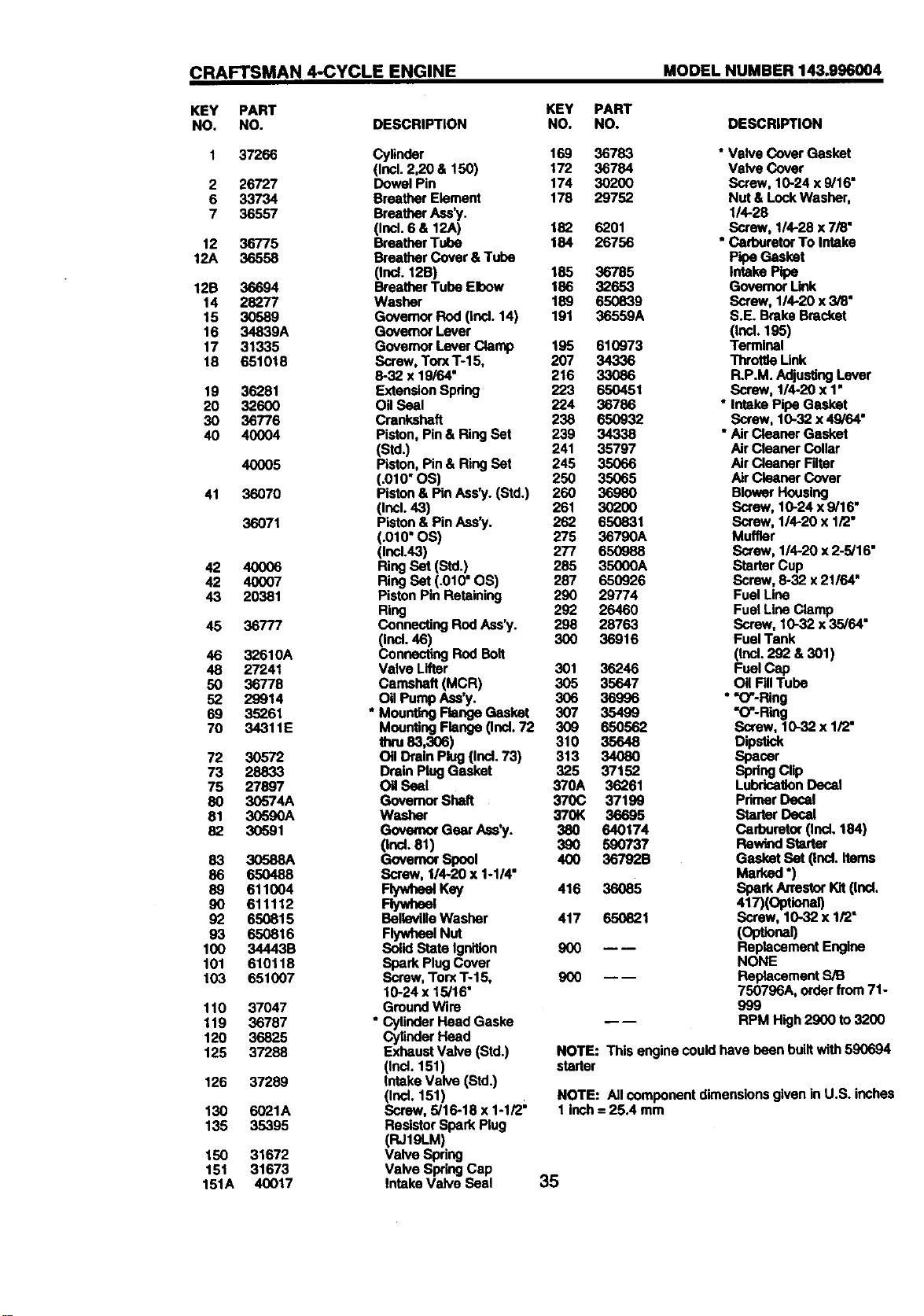
CRAFTSMAN 4-CYCLE ENGINE MODEL NUMBER 143.996004
KEY PART
NO. NO.
---- 640174
1 631615
2 631767
4 631184
5 631183
6 640070
7 650506
16 631807
17 651025
18 630766
20 640018
20A 640053
25 631867
27 631024
28 632019
29 631028
30 631021
31 631022
35 36045A
36 64OO80
36A 632766
37 632547
40 640175
44 27110A
47 630748
48 631027
48A 631027
• 60 632760
DESCRIPTION
Carburetor(Ind. 184 of EnginePartsList)
ThrottleShaft& Lever Assembly
"rnmttleReturnSpdng
* DustSeal Washer
* DustSeal (ThrotUer
ThrottleShutter
"Shutler Screw
Fue_Fitting
ThroUleCrackScrew/IdleSpeed Screw
TensionSpdng
Idle RestdctorScrew
Idle RestrictorScrew Cap
Float Bowl
* Float Shaft
Roat
• Fleat Bowl"O" Ring
• Inlet Needle, Seat, & Clip(Ind. 31)
SpdngClip
PrimerBulb/RetainerRing
Main Nozzle Tube
CarburetorTube
• "O"Ring,Main Nozzle Tube
HighSpeed BowlNut
Bowl Nut Washer
• Welch Plug,IdleMixtureWell
• Welch Plug,AtmospbedcVen
• Welch Plug
Repairkit (Ind. ItemsMarked•)
36
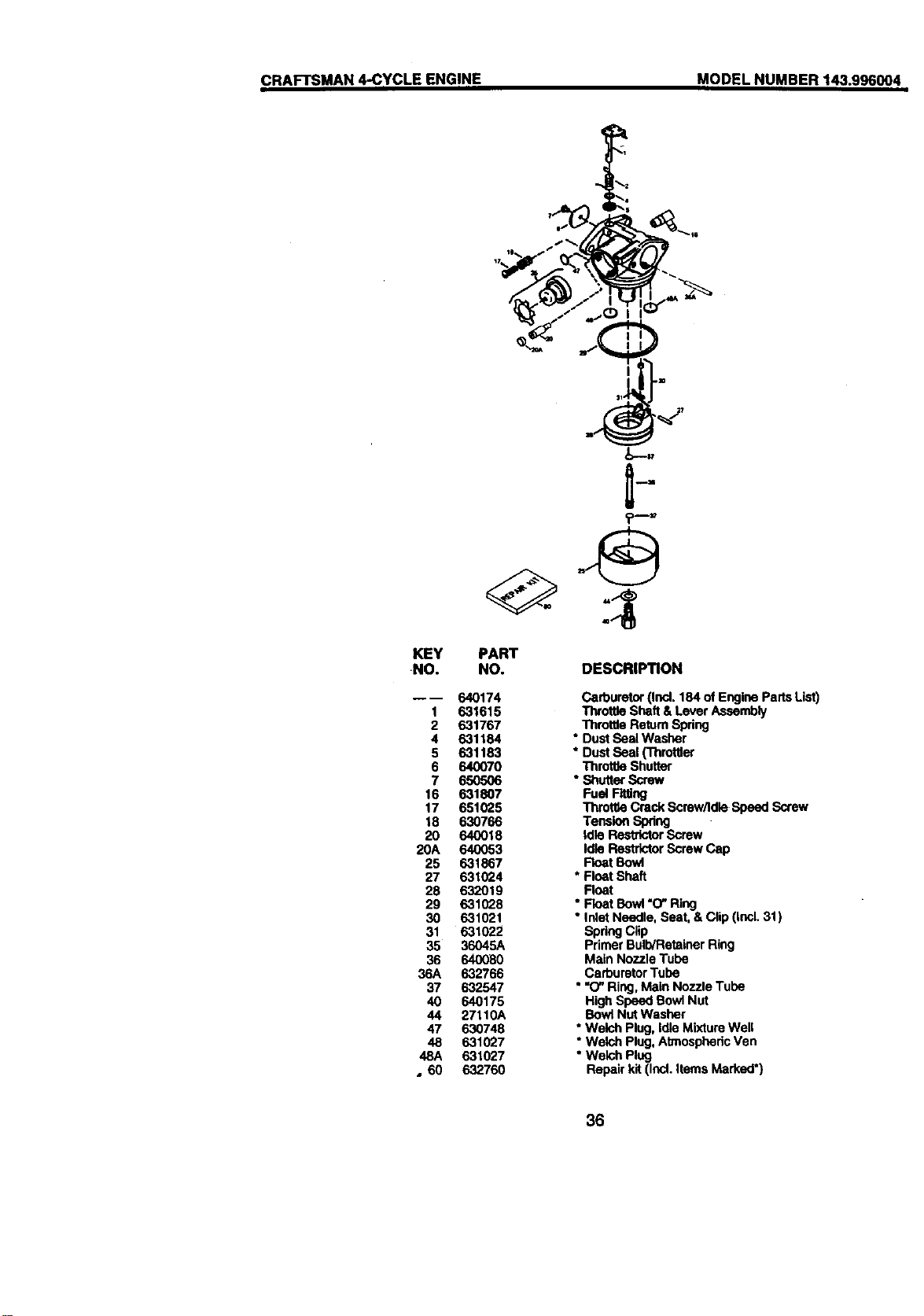
CRAFTSMAN 4-CYCLE ENGINE MODEL NUMBER 143.996004
B--5
OE2
0--'
KEY
NO.
B--
1
2
3
4
5
6
7
8
11
12
13
PART
NO.
590694
590599A
59O6OO
59O696
590601
590697
590698
59O699
590700
59O695
590535
590701
DESCRIPTION
RecogStarter
SpringPin (Incl. 4)
Washer
Retainer
Washer
erakeSpring
StarterDog
DogSp_ng
Pulley& RewindSpdng
Ass'y.
StarterHousingAss',/.
(40 degree grommet)
StartarRope ( 98" X 9/
64"dia.)
StarterHandle
_--14
/
13
12
._:,.._. _-----:_._,.:.::_Si
II III--7
_;'
KEY
NO.
3
6
7
8
11
12
13
14
PART
NO.
590737
590740
590616
590617
590618A
590687A
590535
590701
590760
DESCRIPTION
RewindStarter
Retainer
Starter Dog
DogSpring
Pulley& RewindSpdng
A.'y
StarterHousingAss'y
(40 degree grommet)
StarterRope (Length98"
x9/64" dia.)
StarterHandle
SpringClip
37
Fortherepairorreplacementpartsyouneed
delivereddirectlytoyourhome
Call7am-7pm,7daysaweek
1-800-366-PART
(1-800-366-7278)
Para ordenar piezas con entrega a
domicilio - 1-800-659-7084
For in-house major brand repair service
Call 24 hours a day, 7 days a week
1-800-4-REPAIR
(1-800-473-7274)
Para pedir servicio de reparaci6n a
domicilio - 1-800-676-5811
For the location of a Sears Parts and
Repair Center in your area
Call 24 hours a day, 7 days a week
1-800-488-1222
mmmmmm
mmmmmm
For information on purchasing a Sears
Maintenance Agreement or to inquire
about an existing Agreement
Call 9 am - 5 pm, Monday-Saturday
1-800-827-6655
When requesting service or ordering
parts, always provide the following
information:
• Product Type • Part Number
• Model Number • Part Descdption
SKARS
America's Repair Specialists
166494 REV.1 02.15.99 VB Printed in U.S.A.