/W/// /q
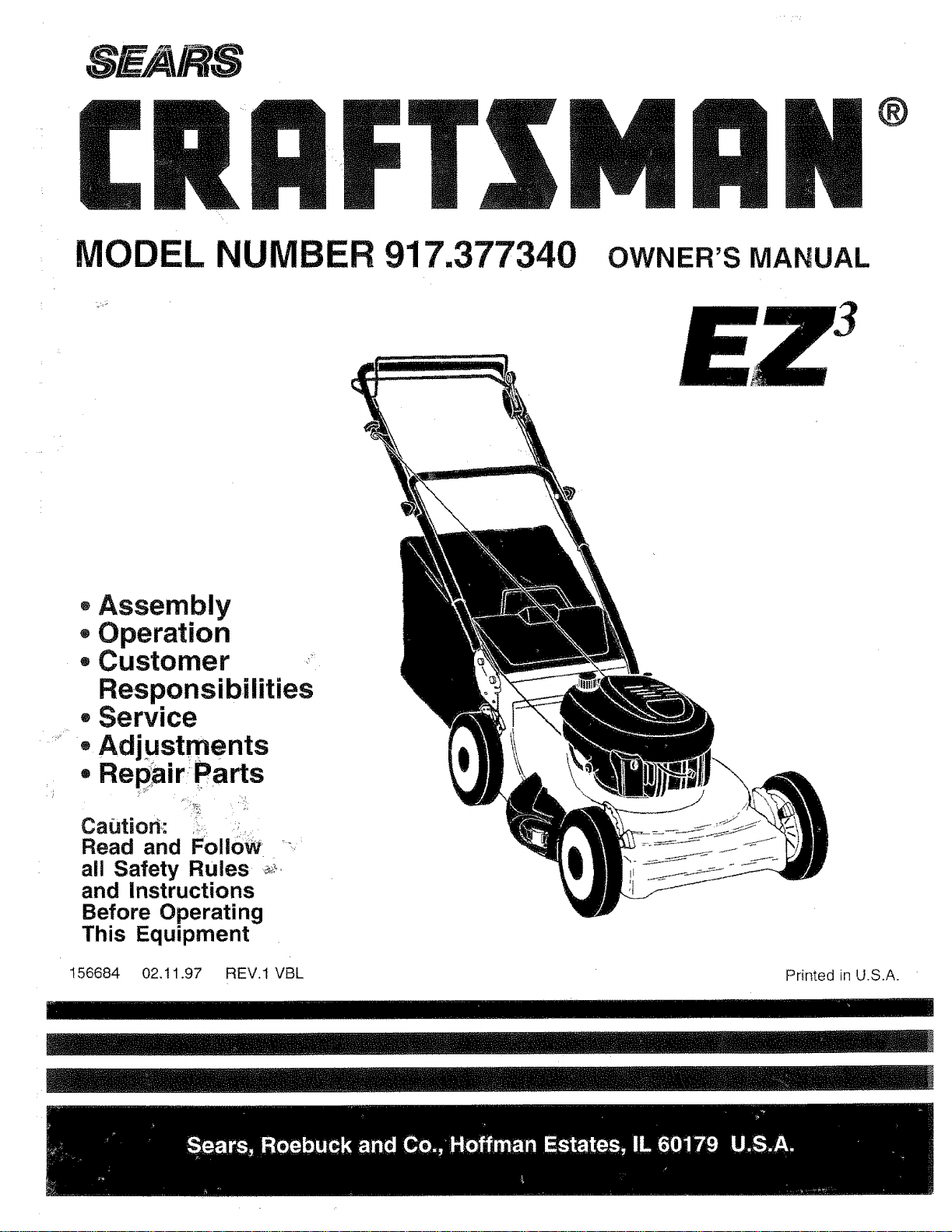
MODEL 917.377340 OWNER'SMANUAL
oAssembly
- Operation
• Customer ,,....
Responsibilities
• Service
• Adjustments
. Repair_Parts
Cautiom
Read and FollOW __,_
all Safety Rules _,_
and Instructions
Before Operating
This Equipment
156684 02.11.97 REV.1 VBL
SAFETY RULES
Safe Operation Practices for Walk-Behind Mowers
IMPORTANT: THIS CUTTING MACHINE IS CAPABLE OF AMPUTATING HANDS AND FEET AND THROWING OBJECTS.
FAILURE TO OBSERVE THE FOLLOWING SAFETY INSTRUCTIONS COULD RESULT IN SERIOUS INJURY OR DEATH.
SAFETY STANDARDS REQUIRE OPERATOR PRESENCE CONTROLS TO MINIMIZE THE RISK OF INJURY. YOUR UNIT IS
EQUIPPED WITH SUCH CONTROLS. DO NOT ATTEMPT TO DEFEAT THE FUNCTION OF THE OPERATOR PRESENCE
CONTROLS UNDER ANY CIRCUMSTANCES.
TRAINING:
o Read this operator's manual carefully. Become familiar with
the controls and know how to operate your mower properly.
Learn how to quickly stop mower,
• Do not allow children to use your mower. Never allow adults
to use mower without proper instructions.
• Keep the area of operation clear of all persons, especially
small children and pets.
, Use mower only as the manufacturer intended and as de-
scribed in this manual.
• Do not operate mower if it has been dropped or damaged in
any manner. Always have damage repaired before using
your mower.
, Donot use accessory attachments that are not recommended
by the manufacturer. Use of such attachments may be
hazardous.
The blade turns when the engine is running.
PREPARATION:
, Always thoroughly check the area to be mowed and clear it of
all stones, sticks, wires, bones, and other foreign objects.
These objects will be thrown by the blade and can cause
severe injury.
Always wear safety glasses or eye shields when starting and
while using your mower.
- Dress properly. Do not operate mower when barefoot or
wearing open sandals. Wear only solid shoes with good
traction when mowing.
Check fuel tank before starting engine. Do not fil! gas tank
indoors, when the engine is running or when the engine is hot.
Allow the engine to cool for several minutes before filling the
gas tank. Clean off any spilled gasoline before starting the
engine.
* Always make wheel height adjustments before starting your
mower, Never attempt to do this while the engine is running.
° Mow only in daylight or good artificia! light.
OPERATION:
Keep your eyes and mind on your mower and the area being
cut. Do not tel other interests distract you.
Do not mow wet or slippery grass. Never run while operating
your mower. Always be sure of your footing- keep a firm hold
on the handles and walk,
• Do not put hands or feet near or under rotating parts. Keep
clear of the discharge opening at all times.
• Always stop the engine whenever you leave or are not using
your mower, or before crossing driveways, walks, roads, and
any gravel-covered areas.
• Never direct discharge of material toward bystanders nor
allow anyone near the mower while you are operating it.
• Before cleaning, inspecting, or repairing your mower, stop the
engine and make absolutely sure the blade and all moving
parts have stopped. Then disconnect the spark plug wire and
keep it away from the spark plug to prevent accidental
starting,
° Do not continue to run your mower if you hit a foreign object.
Follow the procedure outlined above, then repair any dam-
age before restarting and operating you mower.
• Do not change the governor settings or overspeed the
engine. Engine damage or personal injury may result.
o Do not operate your mower if itvibrates abnormally. Exces-
sive vibration is an indication of damage; stop the er_gine,
safely check for the cause of vibration and repair as required.
• Do not run the engine indoors. Exhaust fumes are danger-
ous,
• Never cut grass by pulling the mower towards you. Mow
across the face of slopes, never up and down or you might
toseyour footing. Do not mow excessively steep slopes. Use
caution when operating the mower on uneven terrain or when
changing directions - maintain good footing.
• Never operate your mower without proper guards, plates,
grass catcher or other safety devices in place.
MAINTENANCE AND STORAGE:
Check the blade and the engine mounting bolts often to be
sure they are tightened properly.
o Check all bolts, nuts and screws at frequent intervals for
proper tightness to be sure mower is in safe working condi-
tion.
. Keep all safety devices in place and working.
To reduce fire hazard, keep the engine free of grass, leaves
or excessive grease and oil.
Check grass catcher often for deterioration and wear and
replace worn bags. Use only replacement bags that are
recommended by and comply with specifications of the
manufacturer of your mower.
- Always keep a sharp blade on your mower.
° Allow engine to cool before storing in any enclosure.
Never store mower with fuel in the tank inside a building
where fumes may reach an open flame or an ignition source
such as a hot water heater, space heater, clothes dryer, etc.
Look for this symbol to point out impor-
tant safety precautions, it means
CAUTION!!t BECOME ALERTI!t YOUR
SAFETY IS INVOLVED.
_sconnect spark plug
,_ w_p r_w_hreie tcannot contact
J _ spark p_to prevent accidental
_ start_,ing up, transporting,
..... adjusting or making repairs.
& WARNING & 1
The engine exhaust from this product contains
chemicals known to the State of Californiato cause |
cancer, birth defects, or other reproductive harm,
' 2
FELICITACIONES porlacompra desu segadora Sears Craftsman.
Ha sido diseSada, planificada y fabdcada para dade la mejor
confiabilidad y el mejor rendimiento posibfes.
En el caso de que se encuentre con eualquier problema que no
pueda solucionar fAcitmente, haga etfavor de ponerse en contac-
to con su Centro/Departamento de Servicio Sears m_s cercano.
Sears cuenta con t_cnicos bien capacitados y competentes y con
las herramientas adecuadas para darle servicio o para reparar su
unidad,
Haga et favor de iee_y de guardar este manual. Estas instruccio-
nes le permitir,_n montar y mantener su segadora en forma
adecuad a..Siempre observe las "REGLAS DE SEGURIDAD."
NOMERO DE
MODELO 917.377340
NOMERO DE
SERIE
FECHA DE
COMPRA
EL NOMERO DEL MODELO Y EL DE SERIE SE ENCUEN-
TRAN EN LA CALCOMANIA ADJUNTA A LA PARTE TRA-
SERA DE LA CAJA DE LA SEGADORA,
DEBE REGISTRAR TANTO EL NOMERO DE SERIE COMO
LA FECHA DE COMPRA Y MANTENGALOS EN UN LU-
GAR SEGURO PARA REFERENCIA EN EL FUTURO,
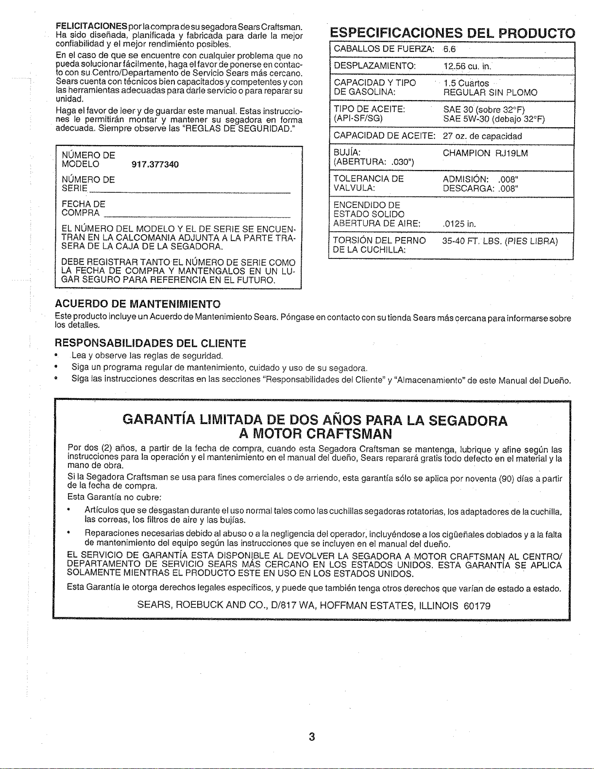
ESPECIF!CACIONES DEL PRODUCTO
CABALLOS DE FUERZA: 6.6
DESPLAZAMIENTO:
CAPACIDAD Y TIPO
DE GASOLINA:
TIPO DE ACEITE:
(API-SFiSG)
12.56 cu. in.
t.5 Cuartos
REGULAR SIN PLOMO
.... ,,, ,,,,
SAE 30 (sobre 32°F)
SAE 5W,30 (debaio 32°F)
CAPACIDAD DE ACEITE: 27 oz. de capacidad
BUJ[A: CHAMPION RJ19LM
(ABERTURA: .030")
TOLERANClA DE ADMfSlON: .008"
VALVULA: DESCARGA: .008"
ENCENDIDO DE
ESTADO SOL[DO
ABERTURA DE AtRE; .0125 in.
TORSION DEL PERNO 35-40 FT. LBS. (PIES LIBRA)
DE LA CUCHILLA:
ACUERDO DE MANTENIMIENTO
Este producto incluye un Acuerdo de Mantenimiento Sears. P6ngase en contacto con su tienda Sears m_s oercana para informarse sobre
los detaties.
RESPONSABILIDADES DEL CLIENTE
• Lea y observe ]as reglas de seguridad.
° Siga un programa regular de mantenimiento, cuidado y uso de su segadora.
Siga tas instrucciones descritas en ]as secciones "Responsabilidades det Cliente" y "Almacenamiento" de este Manual del Due_o.
GARANT[A LHMITADA DE DOS ANOS PARA LA SEGADORA
A MOTOR CRAFTSMAN
Pot dos (2) afios, a partir de Ia fecha de compra cuando esta Segadora Craftsman se mantenga lubrique y afine seg_n las
instrucciones para la operaci6n y el mantenimiento en et manual det duefio, Sears reparar& gratis todo defecto en el material y la
mano de obra.
Si la Segadora Craftsman se usa para fines comerciales o de arriendo, esta garant[a s6fo se aplica por noventa (90) d[as a parlir
de la fecha de compra,
Esta Garant[a no cubre:
• Art[culos que se desgastan durante el uso normal tales como las cuchiilas segadoras rotatorias, los adaptadores de la cuchilla,
las correas, los fiftros de aire y las buj[as.
• Reparaciones necesarias debido al abuso o a tanegligencia del operadorl incluy_,ndose a los cig(_efiales doblados y a la falta
de mantenimiento del equipo segQn las instrucciones que se incluyen en el manual del dueSo.
EL SERVIClO DE GARANT[A ESTA DtSPONtBLE AL DEVOLVER LA SEGADORA A MOTOR CRAFTSMAN AL CENTROi
DEPARTAMENTO DE SERVlCtO SEARS M,_S CERCANO EN LOS ESTADOS UNIDOS ESTA GARANTiA SE APLCA
SOLAMENTE MtENTRAS EL PRODUCTO ESTE EN USO EN LOS ESTADOS UN1DOS.
Esta Garantia le otorga derechos tegales especfficos, y puede que tambi_n tenga otros derechos que vat[an de estado a estado.
SEARS, ROEBUCK AND CO., D/817 WA, HOFFMAN ESTATES, ILLINOIS 60179
3
..... i
TA LA IAS
REGLAS DE SEGUR_DAD ......................... _ ......... _ ........ 2
ESPECtF|CACIONES DEL PRODUCTO ...................... 3
RESPONSABILiDADES DEL CLIENTE ............ 3, 12-!5
GARANTiA .................................................................... 3
MONTAJE ................................................................... 6-7
OPERACION ............................................................ 8-11
PROGRAMA DE MANTENIMIENTO ...................... .o.o12
SERVIClO Y AJUSTES ............................................... 16
ALMACENAMtENTO ................................................... !7
tDENTIFICAC|ON DE PROBLEMAS ........................... 18
PARTES DE REPUESTO .................. VEA EL MANUAL
iNGLES DEL L3UENO
ORDEN DE PARTES/SERVIC!O ................................ 20
iNDICE
A
Aceite:
Almacenamiento .......................... t 7
Motor .............................................. 9
Acuerdo de mantenimiento ................. 12
Ajustes:
Altura de corte ................................ 9
Altura del mango .......................... t6
Carburador ................................... t6
Vetocidad del motor ....................... 9
Almacenamiento ................................. t 7
Arranque det motor ............................. 10
B
Bujfa .................................................... 15
C
Combustible:
Almacenamiento. ......................... 17
Capacidad .................................... I0
Tipo .............................................. 10
Control de la velocidad:
Motor .............................................. 8
Controles:
Barra de control que exige la
presencia deI operador ................. 8
Control de la impulsi6n .................. 8
Control de la velocidad del motor .. 8
Control de la zona del motor .......... 8
Consejos para segar ........................... 11
Cuchitta:
Afilamiento ................................... 13
Cambio ......................................... 13
E
Especificaciones ................................... 3
F
Filtro de Aire:
Servicio ........................................ t 5
G
Garantia ................................................ 3
L
Lubricaci6n:
Motor ............................................ t4
Segadora ..................................... t2
M
Mango:
Ajuste ........................................... 18
Montaje ....................................... 6-7
Montaje .............................................. 6-7
Motor:
Almacenamiento .......................... 18
Arranque ...................................... 11
Cambio de aceite .......... ;............... t4
Filtro de aire ................................. !5
Nivet de aceite ............................. 14
Parada ..................................... _.. 11
Tipo de aceite .............................. 14
N
Niveles de corte .................................... 9
O
Opciones:
Accesorios ...................................... 5
Operaci6n:
Barra de control que exige la
presencia del operador .................. 8
Control de la impulsi6n .................. 8
Control del motor ............................ 8
P
Parada del motor .................................. 11
Programa de mantenimiento. .............. 12
R
Reglas de seguridad ............................. 2
Responsabitidades del Cliente .- 3, 12-15
Buj[a ............................................. 15
Cuidado de la cuchiildcambio ..... 13
Filtro de aire ................................. 15
Lubricaci6n ....................... ............ 12
Motor ............................................ 15
S
Servicio y Ajustes:
Carburador .................................... 16
Control de impulsi6n .................... 16
Mango .......................................... 16
Pr0tecci6n contra Ia descarga ..... 16
Velocidad del motor ..................... 16
Tabia para la identificaci6n de
probfemas .......................................... 18
4
LAWN ACCESSO ES
..... i
z
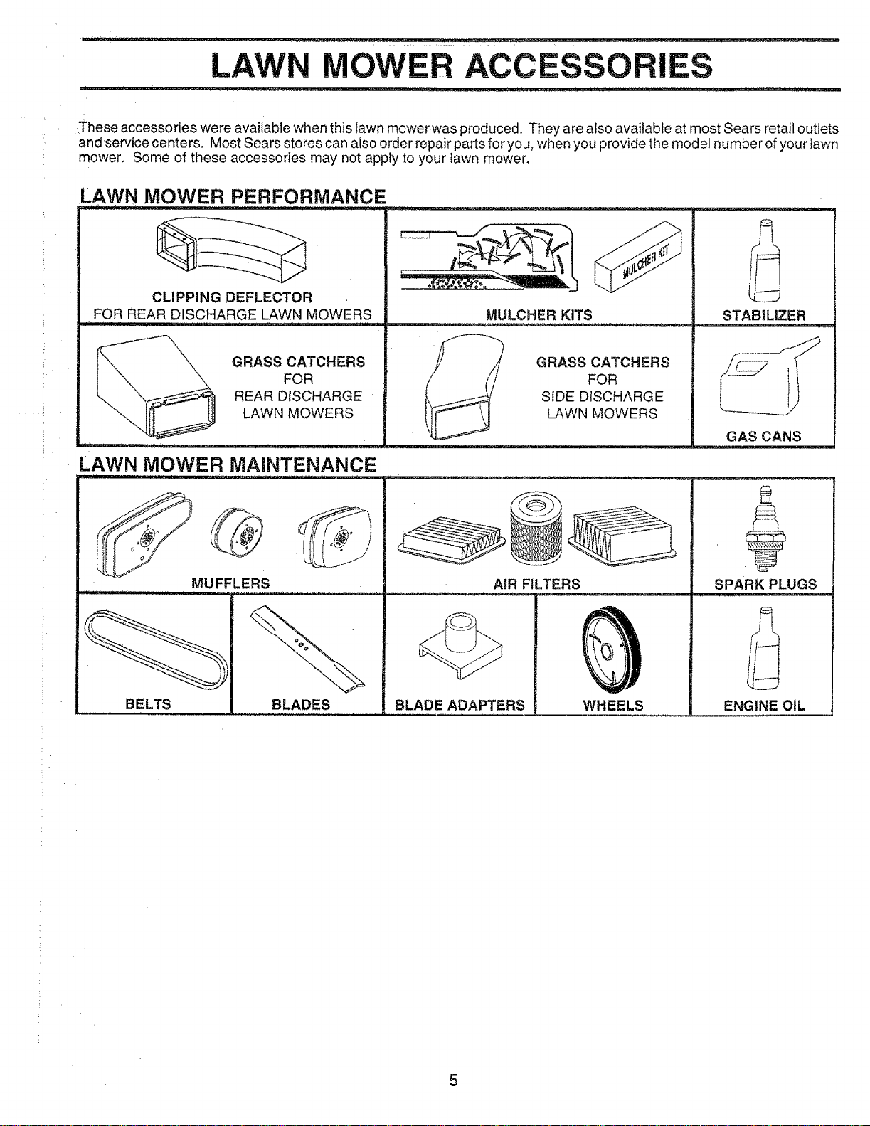
,These accessories were available when this lawn mower was produced. They are also available at most Sears retail outlets
and service centers. Most Sears stores can also order repair parts for you, when you provide the mod el number of your lawn
mower, Some of these accessories may not apply to your lawn mower,
AWN MOWER PERFORMANCE .......
CLIPPING DEFLECTOR
FOR REAR DISCHARGE LAWN MOWERS
GRASS CATCHERS
FOR
REAR DISCHARGE
LAWN MOWERS
LAWN MOWER MAINTENANCE
MUFFLERS
MULCHER KITS
GRASS CATCHERS
FOR
SIDE DISCHARGE
LAWN MOWERS
BELTS BLADES
STABILIZER
GAS CANS
BLADE ADAPTERS
AIR FILTERS
WHEELS
SPARK PLUGS
ENGINE OIL
5
ASSE BLY
Read these instructions and this manual in its entirety
before you attempt to assemble or operate your new lawn
mower. Your new lawn mower has been assembled at the
factory with the exception of those parts left unassembled
for shipping purposes. To ensure safe and proper opera-
tion of your lawn mower, all parts and hardware you
assemble must be tightened securely. Use the correct
tools as necessary to ensure proper tightness. All parts
such as nuts, washers, bolts, etc., necessary to complete
the assembly have been placed in the parts bag.
TO RE_,_OVE LAWN MOWER FROM
CARTON
o Remove loose parts inciuded with mower.
o Cut down two end corners of carton and lay end
panel down flat.
o Remove atl packing materials except padding be-
tween upper and lower handle and padding holding
operator presence control bar to upper handle.
• Roll lawn mower out of carton and check carton
thoroughly for additional loose parts.
HOWTO SET UPYOUR LAWN
MOWER
UPPER HANDLE
LiFT UP
r_OWING
POSITION
LOWER HANDLE
HANDLE
PiN
FmGo1
/
J
\
\
3-POSITION
NDLE
ADJ USTMENT
BRACKET
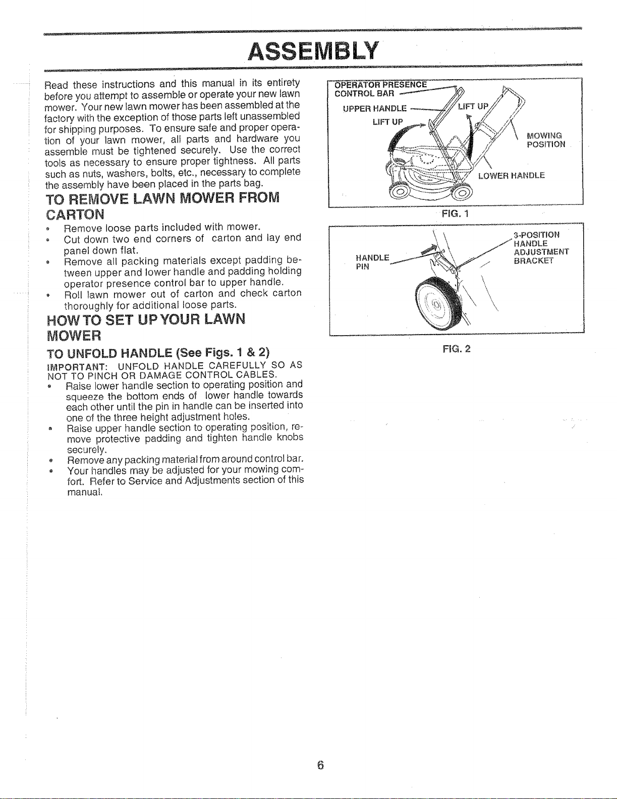
TO UNFOLD HANDLE: (See Figs. t & 2)
t&_PORTANT: UNFOLD HANDLE CAREFULLY SO AS
NOT TO PINCH OR DAMAGE CONTROL CABLES,
o Raise lower handle section to operating position and
squeeze the bottom ends of lower handle towards
each other until the pin in handle can be inserted into
one of the three height adjustment holes.
° Raise upper handle section to operating position, re-
move protective padding and tighten handle knobs
securely.
Remove any packing material from around control bar.
• Your handies may be adjusted for your mowing com-
fort. Refer to Service and Adjustments section of this
manual
F_G,2
6
BLY
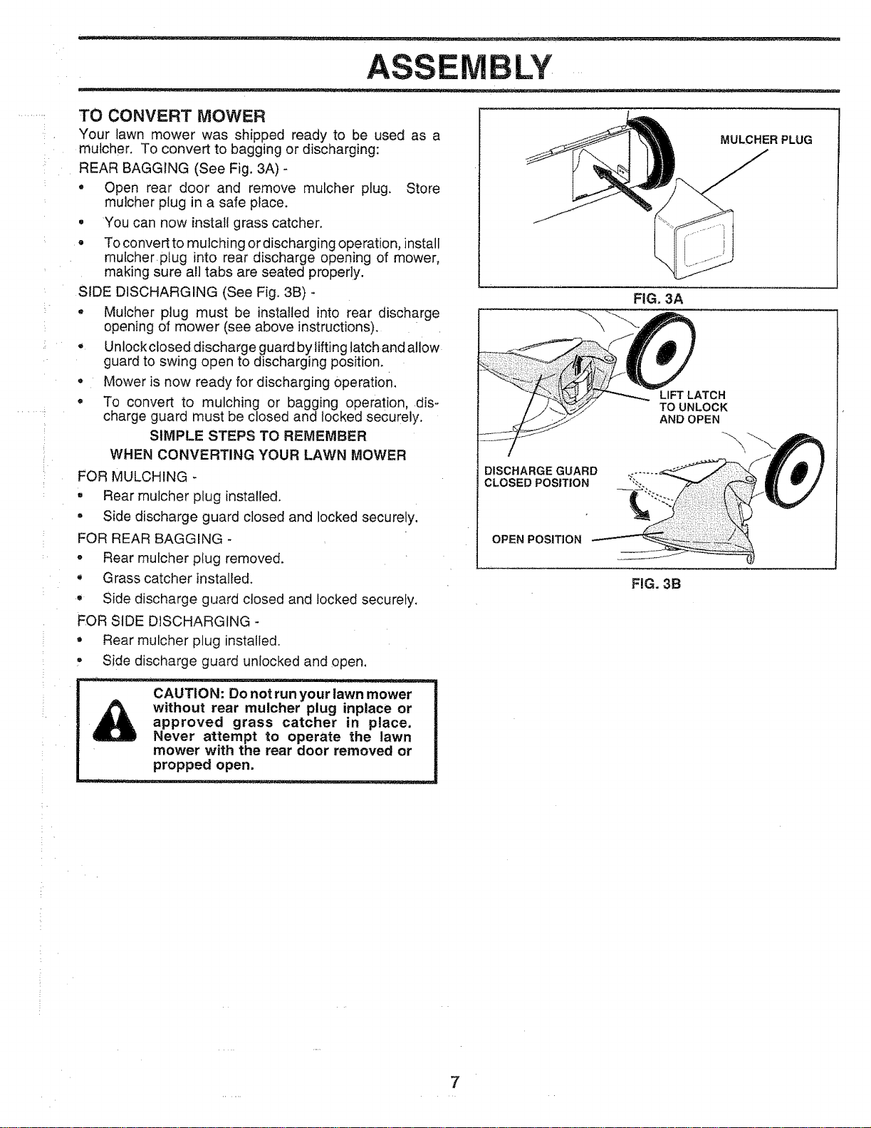
TO CONVERT MOWER
Your lawn mower was shipped ready to be used as a
mulcher. To convert to bagging or discharging:
REAR BAGGING (See Fig. 3A) -
, Open rear door and remove mulcher plug. Store
mulcher plug in a safe place.
, You can now install grass catcher.
To convert to mulching or discharging operation, install
mutcher plug into rear discharge opening of mower,
making sure all tabs are seated properly.
SIDE DISCHARGING (See Fig. 3B) -
* Mulcher plug must be installed into rear discharge
opening of mower (see above instructions).
Unlock closed discharge guard by lifting tatch and allow
guard to swing open to discharging position.
o Mower is now ready for discharging operation.
, To convert to mulching or bagging operation, dis-
charge guard must be closed and locked securely.
SIMPLE STEPS TO REMEMBER
WHEN CONVERTING YOUR LAWN MOWER
FOR MULCHING -
° Rear mulcher plug installed.
° Side discharge guard closed and locked securely.
FOR REAR BAGGING -
o Rear mufcher ptug removed.
Grass catcher installe&
e Side discharge guard closed and locked securely.
}=OR SIDE DISCHARGING -
, Rear mulcher plug installed.
w Side discharge guard unlocked and open.
CAUTION: Do not run your lawn mower
without rear mulcher plug inplace or
approved grass catcher in place,
Never attempt to operate the lawn
mower with the rear door removed or
propped open.
MULCHER PLUG
FIG=3A
DISCHARGE GUARD
CLOSED POSITION
OPEN POSITION
LIFT LATCH
TO UNLOCK
AND OPEN
FiG. 3B
7
OPERATIC
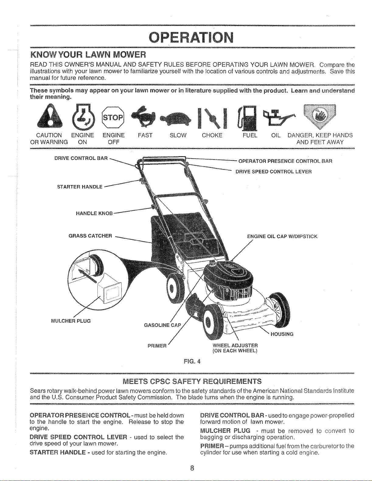
KNOWYOUR LAWN MOWER
READ THIS OWNER'S MANUAL AND SAFETY RULES BEFORE OPERATING YOUR LAWN MOWER. Compare the
illustrations with your lawn mower to familiarize yourself with the location of various controls and adjustments. Gave this
manual for future reference.
These symbols may appear on your lawn mower or in literature supplied with the product° Learn and _Jr_derstand
their meaning.
&
CAUTION
OR WARNING
SLOWENGINE FAST
OFF
\
CHOKEENGINE FUEL
ON
OIL DANGER KEEP HANDS
AND FEET AWAY
DRIVE CONTROLBAR
OPERATOR PRESENCE CONTROL, BAR
DRIVE SPEED CONTROL LEVER
STARTER HANDLE
HANDLE KN(
GRASS CATCHER
ENGINE OIL CAP WtDIPSTUCK
MULCHER PLUG
GASOLINECAP
HOUSING
PF{IMER WH EEL ADJ USTER
(ON EACH WHEEL)
FIG. 4
MEETS CPSC SAFETY REQUIREMENTS
Sears rotary walk-behind power lawn mowers conform to the safety standards of the American National Standards Institute
and the U.S. Consumer Product Safety Commission. The blade turns when the engine is running,
OPERATOR PRESENCE CONTROL- must be held down
to the handle to start the engine. Release to stop the
engine.
DRIVE SPEED CONTROL LEVER - used to select the
drive speed of your lawn mower.
STARTER HANDLE * used for starting the engine.
DR_VE CONTROL BAR - used to engage poweropropelted
forward motion of _awnmower.
MULCHER PLUG must be removed to convert to
bagging or discharging operation.
PR_,/IIER- pumps additional fuel from the carburetor to the
cylinder for use when starting a cold engine.
8
OP ATIO .......
any lawn mower can result in foreign objects thrown into the eyes, which can result in severe
_._"_ _ eye damage. Always wear safety glassesor eye shields while operating your lawn mower or performing any
_ adjustments or repairs. We recommend awide vision safety mask over the spectacles or standard safety
galsses, _.
HOWTO USE YOUR LAWN MOWER
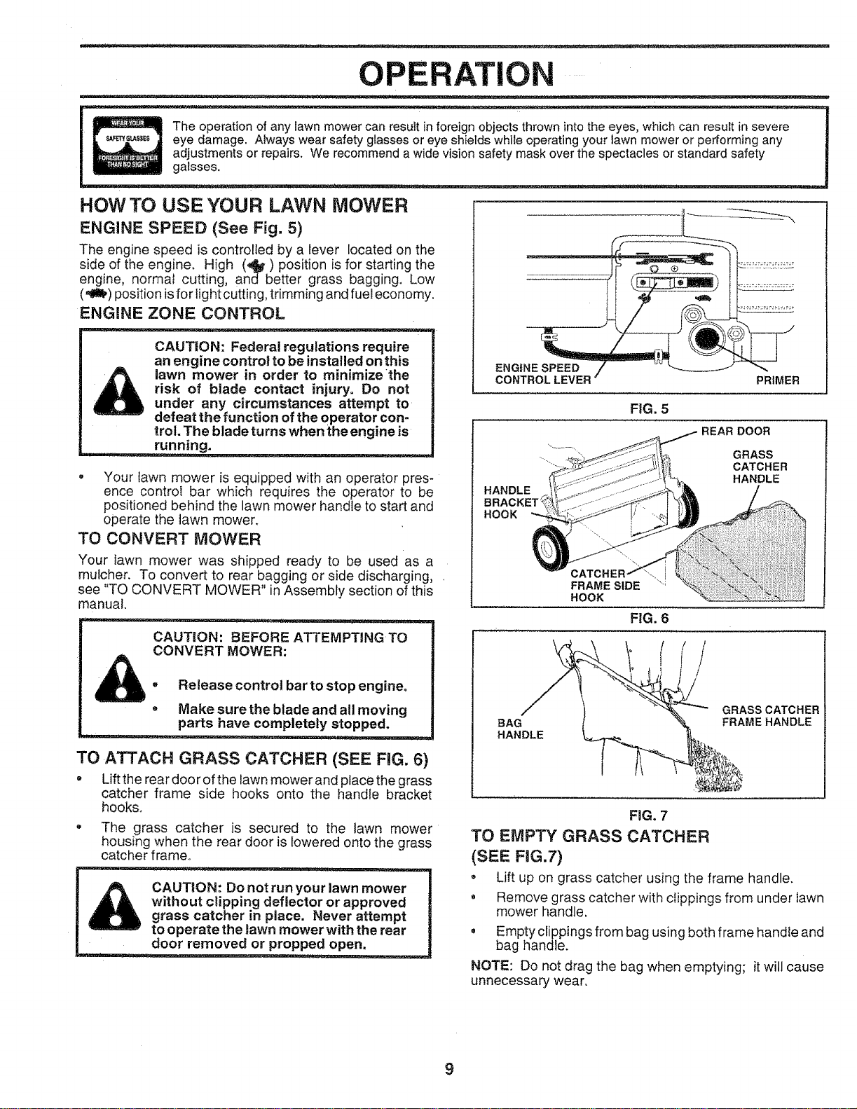
ENGINE SPEED (See Fig, 5)
The engine speed is controlled by a lever located on the
side of the engine. High (41_) position is for starting the
engine, normal cutting, and better grass bagging, Low
(,_!_) position isfor light cutting, trimming and fuel economy.
ENGINE ZONE CONTROL
CAUTION: Federal regulations require
an engine control to be installed on this
lawn mower in order to minimize the
risk of blade contact injury° Do not
under any circumstances attempt to
defeat the function ofthe operator con-
trol. The blade turns when the engine is
• Your lawn mower is equipped with an operator pres-
ence control bar which requires the operator to be
positioned behind the lawn mower handle to start and
operate the lawn mower,
TO CONVERT MOWER
Your _awn mower was shipped ready to be used as a
mutcher. To convert to rear bagging or side discharging, .
see "TO CONVERT MOWER" in Assembly section of this
manual
CAUTION: BEFORE ATTEMPTING TO
CONVERT MOWER:
o Release control bar to stop engine,
, Make sure the blade and all moving
parts have completely stopped.
TO ATTACH GRASS CATCHER (SEE FiG. 6)
° Lift the rear doorof the lawn mower and place the grass
catcher frame side hooks onto the handle bracket
hooks.
The grass catcher is secured to the lawn mower
housing when the rear door is lowered onto the grass
catcher frame.
1
CAUTION: Do not run your lawn mower
without clipping deflector or approved |
grass catcher in place. Never attempt |
to operate the lawn mower with the rear |
d00rremoved, o_
ENGINE SPEED
CONTROL
PRIMER
FiG. 5
REAR DOOR
HANDLE
BRACKET '_
HOOK
GRASS
CATCHER
HANDLE
FRAME SIDE
HOOK
FIG. 6
/
BAG
HANDLE
GRASS CATCHER
FRAMEHANDLE
FIG. 7
TO EMPTY GRASS CATCHER
(SEE FIG.7)
= Lift up on grass catcher using the frame handle.
o Remove grass catcher with clippings from under lawn
mower handle,
• Empty clippings from bag using both frame handle and
bag handle.
NOTE: Do not drag the bag when emptying; it will cause
unnecessary wear.
9
OPERATIO
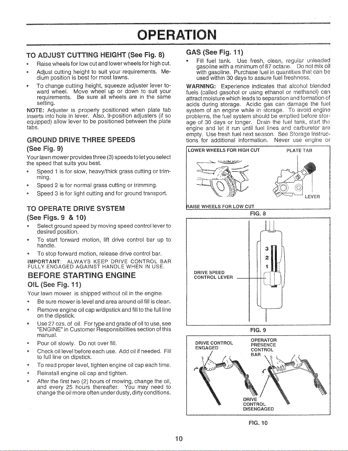
TO ADJUST CUTTING HEIGHT (See Fig. 8)
, Raise wheels for low cut and lowerwheels for high cut.
• Adjust cutting height to suit your requirements. Me-
dium position is best for most lawns.
To change cutting height, squeeze adjuster lever to-
ward wheel. Move wheet up or down to suit your
requirements. Be sure all wheels are in the same
setting.
NOTE: Adjuster is properly positioned when plate tab
inserts into hole in lever. Also, 9-position adjusters (if so
equipped) allow lever to be positioned between the plate
tabs.
GROUND DRIVE THREE SPEEDS
(See Fig. 9)
Your lawn mower provides three (3) speeds to let you select
the speed that suits you best.
,, Speed 1 is for StQW, heavy/thick grass cutting or trim-
ming.
, Speed 2 isfornormal grasscuttingortrimming,
o Speed 3 isforlightcuttingand forground transport.
TO OPERATE DRIVE SYSTEM
(See Figs. 9 & 10)
o Select ground speed by moving speed control lever to
desired position.
* To start forward motion, lift drive control bar up to
handle.
o To stop forward motion, release drive control bar.
IMPORTANT: ALWAYS KEEP DRIVE CONTROL BAR
FULLY ENGAGED AGAINST HANDLE WHEN IN USE.
BEFORE STARTING ENGINE
OIL (See Fig. 11)
Your lawn mower is shipped without oil in the engine.
o Be sure mower is ievel and area around oil fill is clean.
o Remove engine oil cap w/dipstick and fill to the full line
on the dipstick.
Use 27 ozs, of oil. For type and grade of oi!to use, see
"ENGINE" in Customer Responsibilities section of this
manual.
Pour oil slowly. Do not over fill.
o Check oil level before each use+ Add oil if needed. Fill
to fu!l line on dipstick,
,* To read proper level, tighten engine oil cap each time.
, Reinstall engine oil cap and tighten.
o After the first two (2) hours of mowing, change the oil,
and every 25 hours thereafter, You may need to
change the oil more often under dusty, dirty conditions.
GAS (See Fig. 1t)
, Fill fuel tank. Use fresh, clean, regular un eaded
gasoline with a minimum of 87 octane, Do not mix oil
with gasoline. Purchase rue! in quantities that can be
used within 30 days to assure fuel freshness°
WARNING: Experience indicates that alcohol blended
fuels (called gasohol or using ethanol or methanol) can
attract moisture which leads to separation and formation of
acids during storage. Acidic gas can damage the fuei
system of an engine while in storage. To avoid engine
problems, the fuel system should be emptied before storz
age of 30 days or !origen. Drain the fuel tank, start the
engine and let it run until fuel lines and carburetor are
empty. Use fresh fuel next season. See Storage Instruc-
tions for additional information° Never use engine or
LOWER WHEELS FOR HIGH CUT
PLATE TAB
_'_
RAISE WHEELS FOR LOW CUT
FIG. 8
LEVER
DRIVE SPEED
CONTROL LEVER
DRIVE CONTROL
ENGAGED
FIG. 9
OPERATOR
PRESENCE
CONTROL
BAR _X
DRIVE
CONTROL
DISENGAGED
FIG. 10
10
OP RATIO
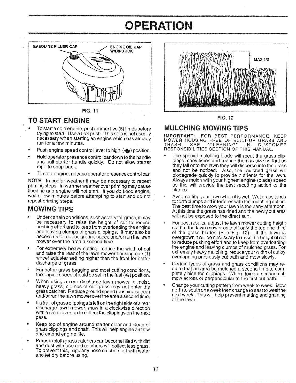
GASOLINE FILLER CAP
ENGINE OtL CAP
W/DIPSTICK
FiG. 11
TO START ENGINE
To start a cold engine, push primer five (5) times before
trying to start. Use a firm push. This step is not usually
necessary when starting an engine which has already
run for a few minutes.
, Push engine speed control lever to high (4) position.
, Hold operator presence control bar down to the handle
and pull starter handle quickly. Do not allow starter
rope to snap back.
• To stop engine, release operator presence control bar,
NOTE: In cooler weather it may be necessary to repeat
priming steps, in warmer weather over priming may cause
flooding and engine will not start, if you do flood engine,
wait a few minutes before attempting to start and do not
repeat priming steps.
MOWING TIPS
Under certain conditions, such as very tail grass, it may
be necessary to raise the height of cut to reduce
pushing effort and to keep from overloading the engine
and leaving clumps of grass clippings, It may also be
necessary to reduce ground speed and/or run the lawn
mower over the area a second time.
• For extremely heavy cutting, reduce the width of cut
and raise the rear of the lawn mower housing one (t)
wheel adjuster setting higher than the front for better
discharge of grass.
For better grass bagging and most cutting conditions,
the engine speed should be set in the fast (@) position.
o When using a rear discharge lawn mower in moist,
heavy grass, clumps of cut grass may not enter the
grass catcher. Reduce ground speed (pushing speed)
and/or run the lawn mower over the area a second time.
• Ifa trail ofgrass clippings is left on the right side of a rear
discharge lawn mower, mow in a clockwise direction
with a small overlap to collect the clippings on the next
pass.
• Keep top of engine around starter clear and clean of
grass clippings and chaff. This wilt help engine airflow
and extend engine life.
Pores incloth grass catchers can become filled with dirt
and dust with use and catchers will collect less grass.
To prevent this, regularly hose catchers off with water
and let dry before using.
MAX 1/3
FIG. 12
MULCHING MOWING TIPS
IMPORTANT: FOR BEST PERFORMANCE, KEEP
MOWER HOUSING FREE OF BUILT-UP GRASS AND
TRASH. SEE "CLEANING" IN CUSTOMER
RESPONSIBILITIES SECTION OF THIS MANUAL.
, The special mulching blade will recut the grass clip-
pings many times and reduce them in size so that as
they fall onto the lawn they will disperse into the grass
and not be noticed. Also, the mulched grass will
biodegrade quickly to provide nutrients for the lawn.
Always mulch with your highest engine (blade) speed
as this witl provide the best recutting action of the
blades.
• Avoid cutting your lawn when it is wet. Wet grass tends
to form clumps and interferes with the mulching action.
The best time to mow your lawn is the early afternoon.
At this time the grass has dried and the newly cut area
wil! not be exposed to the direct sun.
, For best results, adjust the lawn mower cutting height
so that the lawn mower cuts off only the top one-third
of the grass blades (See Fig. 12). If the lawn is
overgrown itwill be necessary to raise the height of cut
to reduce pushing effort and to keep from overloading
the engine and leaving clumps of mulched grass. For
extremely heavy mulching, reduce your width of cut by
overlapping previously cut path and mow slowly.
Certain types of grass and grass conditions may re-
quire that an area be mulched a second time to com-
pletely hide the clippings. When doing a second cut,
mow across or perpendicular to the first cut path.
, Change your cutting pattern from week to week. Mow
north to south one week then change to east to west the
next week. This will help prevent matting and graining
of the lawn.
11
CUSTOM ESPONS L ES
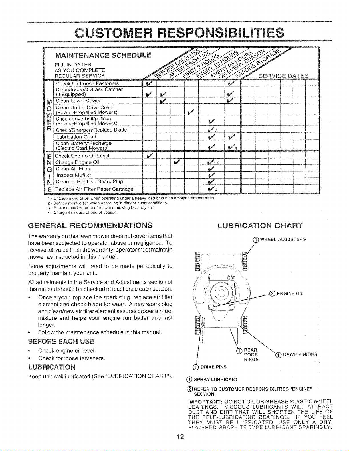
MA_NTENANCESCHEDULE
FILL IN DATES
AS YOU COMPLETE
REGULAR SERV!CE
Check for Loose Fasteners
Clean/Inspect Grass Catcher
(if Equipped)
M1 Clean Lawn Mower
OI
W1
NI
Clean Under Drive Cover
Power_Propelled Mowers)
Check drive belt/pulleys
PoweroPropefled Mowers)
ChecWSharpen/Replace Blade
Lubrication Chart
Clean Battery/Recharge
Electric Start
Check Engine Oil Level
ine Oil
Clean Air Filte_
Inspect Muffler
Clean or Replace Spark Plug
Replace Air Filter Paper Cartridge
! - Change more often when operating under a hea'w ' toad or in high ambient terr
2 - Service more often when operating in dirty or dusty conditions.
3 -RepIace btades more often when mowing in sandy soil,
4 - Charge 48 hours at end of season,
SERVICE DATES
GENERAL RECOMMENDATIONS
The warranty on this lawn mower does not cover items that
have been subjected to operator abuse or negligence. To
receive full value fromthe warranty, operator must maintain
mower as instructed in this manual.
Some adjustments will need to be made periodically to
properly maintain your unit.
All adjustments in the Service and Adjustments section of
this manual should be checked at least once each season.
o Once a year, replace the spark plug, replace air filter
element and check blade for wear. A new spark plug
and clean/new air filter element assures proper air-fuel
mixture and helps your engine run better and last
longer.
, Follow the maintenance schedule in this manual.
BEFORE EACH USE
o Check engine oil level.
o Check for loose fasteners°
LUBRICATION
Keep unit well Iubricated (See "LUBRICATION CHART")°
LUBRICATION CHART
iWHEEL ADJUSTERS
DRIVE PINS
REAR
BOOR
HINGE
ENGINE OIL
'(_ DRIVE PINIONS
(_ SPRAY LUBRICANT
(_) REFER TO CUSTOMER
RESPONSIBILITIES "ENGRNE"
SECTION,
_MPORTANT: DO NOTOILOR GREASE PLASTIC WHEEL
BEARINGS. VISCOUS LUBRICANTS WiLL ATTRACT
DUST AND DIRT THAT WILL SHORTEN THE LIFE OF
THE SELF-LUBRICATiNG BEARINGS, iF YOU FEEL
THEY MUST BE LUBRICATED, USE ONLY A DRY,
POWERED GRAPHITE TYPE LUBRICANT SPARINGLY,
12
CUSTO RESPON
:LAWN MOWER
Always observe safety rules when performing any mainte-
nance.
TIRES
• Keep tires free of gasoline, oil, or insect control chemi-
cals which can harm rubber.
, Avoid stumps, stones, deep ruts, sharp objects and
,other hazards that may cause tire damage.
BLADE CARE
For best results, mower blade must be kept sharp.
Replace bent or damaged blades.
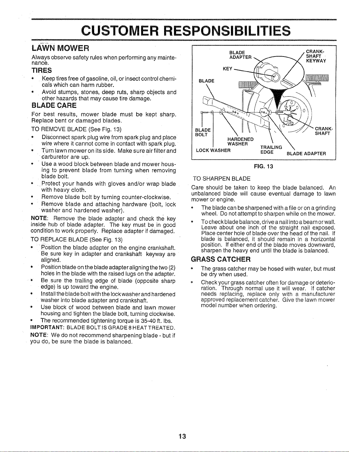
TO REMOVE BLADE (See Fig. 13)
• Disconnect spark plug wire from spark plug and place
wire where it cannot come in contact with spark plug.
• Turntawn mower on its side. Make sure airfilterand
carburetor are up.
, Use:a wood block between blade and mower hous-
ing to prevent blade from turning when removing
blade bolt.
• Protect your hands with gloves and/or wrap blade
with heavy cloth.
,, Remove blade bolt by turning counter-clockwise.
• Remove blade and attaching hardware (bolt, lock
washer and hardened washer).
NOTE: Remove the blade adapter and check the key
inside hub of blade adapter. The key must be in good
condition:to work properly. Replace adapter if damaged.
TO REPLACE BLADE (See Fig. 13)
• #osition the blade adapter on the engine crankshaft.
Besure key in adapter and crankshaft keyway are
aligned.
Position blade on the blade adapter aligning the two (2)
holes in the blade with the raised tugs on the adapter.
Be sure the trailing edge of blade (opposite sharp
edge) is up toward the engine.
• Instal! the blade bolt with the lock washer and hardened
washer into blade adapter and crankshaft.
o Use block of wood between blade and lawn mower
housing and tighten the blade bolt, turning clockwise.
,, The recommended tightening torque is 35-40 ft. fbs.
IMPORI_ANT BLADE BOLT 1SGRADE 8 HEAT TREATED.
NOTE: We do not recommend sharpening blade - but if
you do, be sure the blade is balanced.
BLADE
ILITIES
BLADE
ADAPTER
CRANK-
SHAFT '
KEYWAY
KEY
HARDENED
WASHER
TRAILING
LOCK WASHER EDGE
SHAFT
BLADE ADAPTER
FIG. 13
TO SHARPEN BLADE
Care should be taken to keep the blade ba!anced. An
unba!anced blade will cause eventual damage to lawn
mower or engine.
° The blade can be sharpened with a file or on a grinding
wheel. Do not attempt to sharpen while on the mower.
, To check blade balance, drive a nail into a beam orwal!.
Leave about one inch of the straight nai! exposed.
Place center hole of blade over the head of the nail. If
blade is balanced, it should remain in a horizontal
position. Ifeither end of the blade moves downward,
sharpen the heavy end until the blade is balanced.
GRASS CATCHER
The grass catcher may be hosed with water, but must
be dry when used.
Check your grass catcher often for damage or deterio-
ration. Through normal use it will wear. If catcher
needs replacing, replace only with a manufacturer
approved replacement catcher. Give the lawn mower
model number when ordering.
13
CUSTO RESPON IL ES •
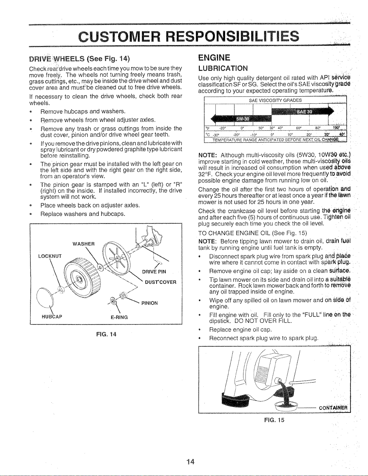
DRI_E:,WHEELS (See Fig. 14)
Check rea:i:drive wheels each time you mow to be sure they
move freel,y. The wheels not turning freely means trash,
grass Cuttings, etc., may be inside the drive wheel and dust
cover area and must;be cleaned out to free drive wheels.
If necessary to clean the drive wheels, check both rear
wheels.
o Remove hubcaps and washers.
o Remove wheels from wheel adjuster axles,
Remove any trash or grass cuttings from inside the
dust cover, pinion and/or drive wheel gear teeth,
o If you remove the drive pinions, clean and lubricate with
spray lubricant or dry powdered graphite type lubricant
before reinstalling.
- Thepinion gear must be installed with the left gear on
the left side and with the right gear on the right side,
from an operator's view.
The pinion gear is stamped with an "L" (left) or "R"
(right) on the inside. If installed incorrectly, the drive
system will not work.
o Place wheels back on adjuster axles.
Replace washers and hubcaps.
HUB-CAP
E-RING
DUS_COVER
PINION
FIG. 14
ENGINE .....
LUBRICATION ..
Use only high quality detergent oil rated with API se_ide
classification SF or SG. Select the oil's SAE viscosity grade
according to your expected operating temperature, ,
SAEVISCOSlTYGRADES
30 _ 32° 40 ,
°C .30 _ .20" .t0 _ 00 _0_
TEMPERATURE RANGE ANTICIPATED BEFORE
NOTE: Although multi-viscosity oils (5W30, 10WS0:dt_,}
improve starting in cold weather, these multi-visc0Stty0iiS
will resu t in ncreased o consumption when used above
32°F. Check your engine oil level more frequently tOawid
possible engine damage from running low on oil. ....
Change the oil after the first two hours of operati0n and
every 25 hours thereafter or at least once a year ifthe lawn
mower is not used for 25 hours in one year.
Check the crankcase oil level before starting the ertgine.
and after each five (5) hours of continuous use. Tighter1 oil
plug securely each time you check the oil level.
TO CHANGE ENGINE OIL (See Fig. 15)
NOTE: Before tipping lawn mower to drain oil, drain fuel
tank by running engine until fuel tank is empty.
• Disconnect spark plug wire from spark plug and 151a_,e
wire where t cannot come n con[act with sparN-plUg, :..
• Remove engine oil cap; lay aside on a clean sljRade,
- Tip tawn mower on its side and drain oil into a sU[ta.bl_
container. Rock lawn mower back and forth to reme£e
any oil trapped inside of engine.
• Wipe off any spilled oil on lawn mower and OhStde 0f
engine. -
• Fill engine with oil. Fill only to the "FULL" line en the .
dipstick, DO NOT OVER FILL.
Replace engine oil cap.
• Reconnect spark plug wire to spark plug.
FIG. 15
14
C STOM ESPONS LITIES
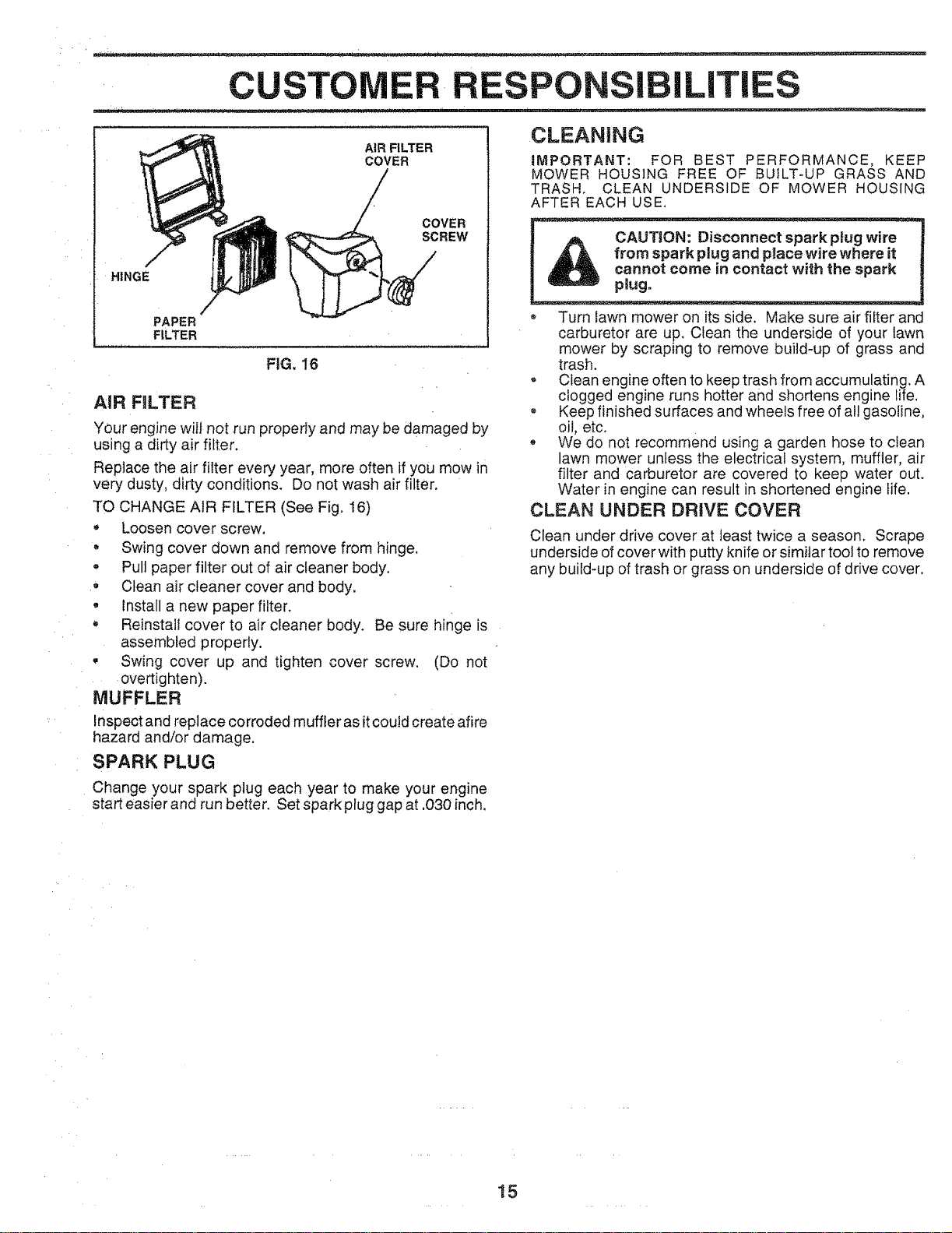
AIR FILTER
COVER
COVER
SCREW
HINGE
PAPER
FILTER
FIG. 16
AIR FILTER
Your engine wilt not run properly and may be damaged by
using a dirty air filter.
Replace the air filter every year, more often if you mow in
very dusty, dirty conditions. Do not wash air filter.
TO CHANGE AIR FILTER (See Fig, 16)
Loosen cover screw.
, Swing cover down and remove from hinge.
, Pull paper filter out of air cleaner body.
• Clean air cleaner cover and body.
° Install a new paper filter.
o Reinstall cover to air cleaner body. Be sure hinge is
assembled properly.
• Swing cover up and tighten cover screw. (Do not
overtig hten).
MUFFLER
Inspect and replace corroded muffler as itcould create afire
hazard and/or damage.
SPARK PLUG
CLEANING
iMPORTANT: FOR BEST PERFORMANCE, KEEP
MOWER HOUSING FREE OF BUILT-UP GRASS AND
TRASH, CLEAN UNDERSIDE OF MOWER HOUSING
AFTER EACH USE.
_. CAUTION: Disconnect spark ptug wire !
u
_L _ from sparkplug and place wire where it |
cannot come in contact with the spark |
plug.
Turn lawn mower on its side. Make sure air filter and
carburetor are up. Clean the underside of your lawn
mower by scraping to remove build-up of grass and
trash.
, Clean engine often to keep trash from accumulating. A
clogged engine runs hotter and shortens engine life,
, Keep finished surfaces and wheels free of all gasoline,
oil, etc.
° We do not recommend using a garden hose to clean
lawn mower unless the electrical system, muffler, air
filter and carburetor are covered to keep water out.
Water in engine can result in shortened engine life.
CLEAN UNDER DRIVE COVER
Clean under drive cover at least twice a season. Scrape
underside of cover with putty knife or similar tool to remove
any build-up of trash or grass on underside of drive cover.
Change your spark plug each year to make your engine
start easier and run better, Set spark plug gap at ,030 inch,
15
SE CE AN ADJUSTMENTS
ORE PERFORMING ANY SERVICE OR ADJUSTMENTS:_=="_-_-===-_'-------=====_==
_ _ ® Release control bar and stop engine.
_, Make sure the blade and all moving parts have completely stopped.
, Disconnect spark plug wire from spark plug and place where it cannot come in contact with plug.
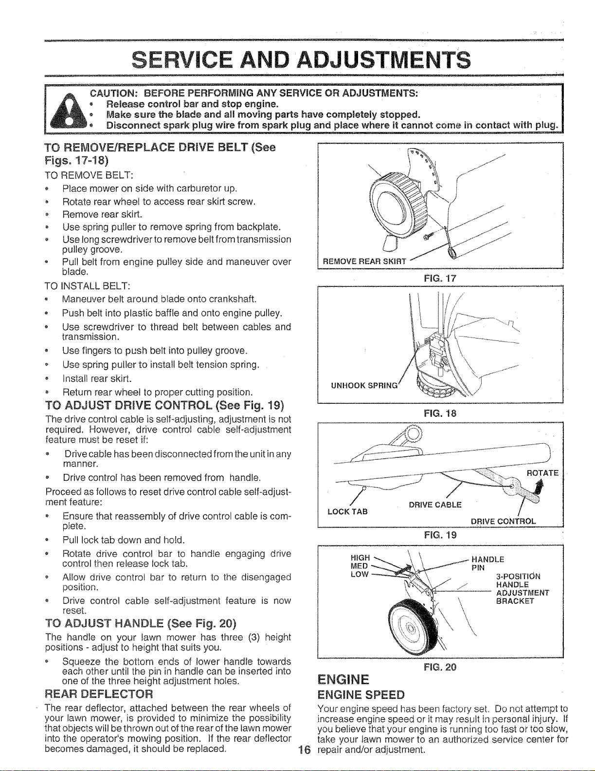
TO REMOVE!REPLACE DRIVE BELT (See
Figs 17-18)
TO REMOVE BELT:
o Place mower on side with carburetor up.
o Rotate rear wheel to access rear skirt screw.
o Remove rear skirt.
Use spring puller to remove spring from backptate.
o Use long screwdriver to remove beetfrom transmission
pulley groove.
• Pul! belt from engine pulley side and maneuver over
blade.
TO iNSTALL BELT:
Maneuver belt around blade onto crankshaft.
Push belt into plastic baffle and onto engine pulley.
o Use screwdriver to thread belt between cables and
transmission.
• Use fingers to push belt into pulley groove.
o Use spring puller to install belt tension spring.
o lnstali rear skirt.
• Return rear wheel to proper cutting position.
TO ADJUST DRIVE CONTROL (See Fig. 19)
The drive control cable is self-adjusting, adjustment is not
required. However, drive control cable self-adjustment
feature must be reset if:
o Drive cable has been disconnected from the unit in any
manner.
o Drive controI has been removed from handle.
Proceed as follows to reset drive control cable self-adjust-
ment feature:
• Ensure that reassembty of drive control cable is com-
plete.
, Pull lock tab down and hold.
UNHOOK
FtGo17
/"
/
FIG, 18
LOCK Ti/AB DRIVE CABLE/" "-°"'_
DRIVE CONTROL
o Rotate drive control bar to handle engaging drive
control then release lock tab,
Allow drive control bar to return to the disengaged
position.
Drive control cable self-adjustment feature is now
reset.
TO ADJUST HANDLE (See Fig. 20)
The handle on your lawn mower has three (3) height
positions - adjust to height that suits you.
o Squeeze the bottom ends of lower handle towards
each other until the pin in handle can be inserted into
one of the three height adjustment holes.
REAR DEFLECTOR
The rear deflector, attached between the rear wheels of
your lawn mower, is provided to minimize the possibility
that objects will be thrown out of the rear of the lawn mower
into the operator's mowing position. If the rear deflector
becomes damaged, it should be replaced.
HiGH
MED
PIN
3-POSITION
HANDLE
ADJUSTMENT
BRACKET
le
FIG. 20
ENGINE
ENGtNE SPEED
Your engine speed has been factory set. Do not attempt tO
increase engine speed or it may result in personal ihjury. If
you believe that your engine is running too fast or too stow,
take your lawn mower to an authorized service center for
repair and/or adjustment.
STO E
Immediately prepare your lawn mower for storage at the
end of the season or ifthe unit will not be used for 30 days
or more.
LAWN MOWER
When lawn mower isto be stored for a period of time, clean
it thoroughly, remove all dirt, grease, leaves, etc. Store in
a clean, dry area.
o Clean entire lawn mower (See "CLEANING" in the
Customer Responsibilities section of this manual).
, Lubricate as shown in the Customer Responsibilities
section of this manual.
, Be sure that all nuts, bolts, screws, and pins are
securely fastened. Inspect moving parts for damage,
breakage and wear. Replace if necessary.
• Touch up all rusted or chipped paint surfaces; sand
lightly before painting.
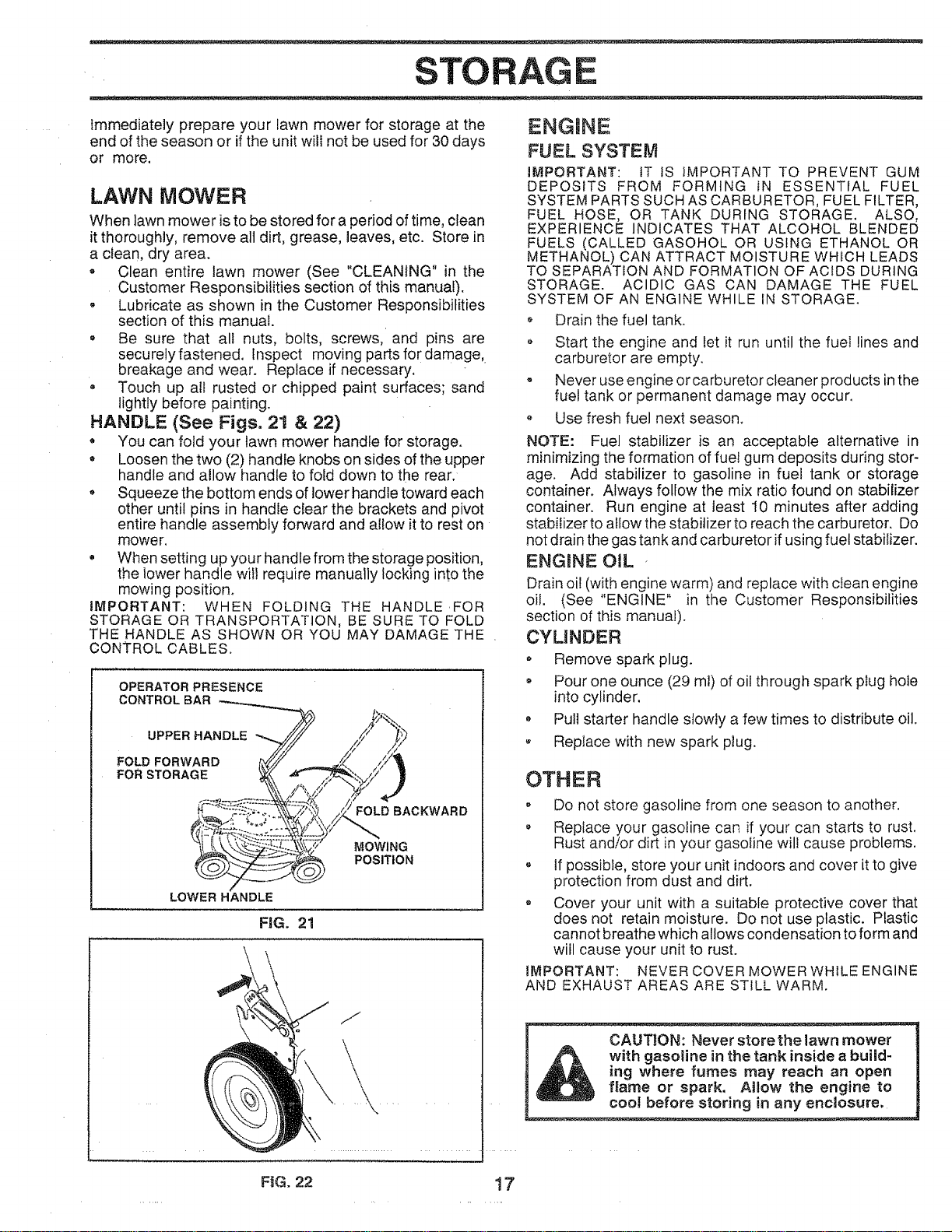
HANDLE (See Figs. 21 & 22)
You can fold your lawn mower handle for storage.
• Loosen the two (2) handle knobs on sides of the upper
handle and allow handle to fold down to the rear.
Squeeze the bottom ends of lower handle toward each
other until pins in handle clear the brackets and pivot
entire handle assembly forward and allow it to rest on
mower.
• When setting up your handle from the storage position,
the lower handle wil! require manually locking into the
mowing position.
IMPORTANT: WHEN FOLDING THE HANDLE .FOR
STORAGE OR TRANSPORTATION, BE SURE TO FOLD
THE HANDLE AS SHOWN OR YOU MAY DAMAGE THE
CONTROL CABLES.
OPERATOR PRESENCE
CONTROLBAR
UPPER HANDLE
FOLD FORWARD
FOR STORAGE
FOLD BACKWARD
MOWING
POSITION
LOWER HANDLE
FIG. 21
\
FiG. 22
ENGINE
FUEL SYSTEM
iMPORTANT: tT IS IMPORTANT TO PREVENT GUM
DEPOSITS FROM FORMING IN ESSENTIAL FUEL
SYSTEM PARTS SUCH AS CARBURETOR, FUEL FILTER,
FUEL HOSE, OR TANK DURING STORAGE. ALSO,
EXPERIENCE INDICATES THAT ALCOHOL BLENDED
FUELS (CALLED GASOHOL OR USING ETHANOL OR
METHANOL) CAN ATTRACT MOISTURE WHfCH LEADS
TO SEPARATION AND FORMATION OF ACIDS DURING
STORAGE. ACIDIC GAS CAN DAMAGE THE FUEL
SYSTEM OF AN ENGINE WHILE IN STORAGE.
Drain the fuel tank.
• Start the engine and let it run until the fuel lines and
carburetor are empty.
• Never use engine or carburetor cleaner products inthe
fuel tank or permanent damage may occur.
Use fresh fuel next season.
NOTE: Fuel stabilizer is an acceptable alternative in
minimizing the formation of fuel gum deposits during stor-
age. Add stabilizer to gasoline in fuel tank or storage
container. Always follow the mix ratio found on stabilizer
container. Run engine at least I0 minutes after adding
stabilizer to allow the stabilizer to reach the carburetor. Do
not drain the gas tank and carburetor if using fuel stabilizer.
ENGINE O_L
Drain oil (with engine warm) and replace with clean engine
oil. (See "ENGINE" in the Customer Responsibilities
section of this manual).
CYLINDER
o Remove spark plug.
o Pour one ounce (29 m!) of oil through spark plug hole
into cylinder.
Pull starter handle slowly a few times to distribute oil.
,, Replace with new spark plug.
OTHER
Do not store gasoline from one season to another.
Replace your gasoline can if your can starts to rust.
Rust and/or dirt in your gasoline wilt cause problems.
o tf possible, store your unit indoors and cover it to give
protection from dust and dirt.
o Cover your unit with a suitable protective cover that
does not retain moisture. Do not use plastic. Plastic
cannot breathe which allows condensation toform and
will cause your unit to rust.
IMPORTANT: NEVER COVER MOWER WHILE ENGINE
AND EXHAUST AREAS ARE STILL WARM.
,_ with ga__ buiid-
,d_, ing where fumes may reach an open
flame or spark, 1Alow the engine to
17
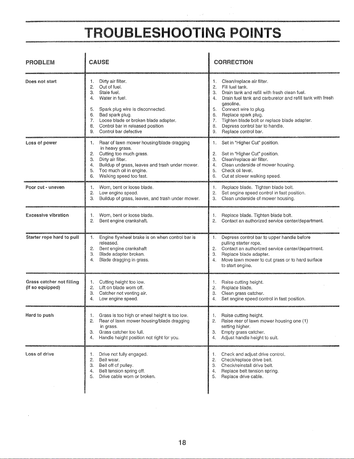
TROU L COTING POINTS
PROBLEM
Does not start
Loss ef power
Poor cut - uneven
Excessive vibration
Starter rope hard to pull
Grass catcher not filling
(If so equipped)
Hard to push
Loss of drive
CAUSE
t. Dirty air filter,
2, Out of fuel,
3, Stale fuet,
4. Waterin fuel+
5. Spark plug wire is disconnected.
6. Bad spark plug.
7, Loose blade or broken blade adapter,
8. Control bar in released position
9, Control bar defective
1. Rear of lawn mower housingfbIade dragging
in heavy grass.
2, Cutting too much grass,
3. Dirty air filter.
4, Buildup of grass, leaves and trash under mower.
5. Too much oil in engine,
6. Walking speed too fast.
t. Worn, bent or toose blade,
2. Low engine speed,
3, Buildup of grass, Ieaves, and trash under mower.
t. Worn, bent or loose blade.
2o Bent engine crankshaft,
1, Engine flywheel brake is on when control bar is
released.
2. Bent engine crankshaft
3, Blade adapter broken.
4, Blade dragging in grass.
1. Cutting height too low,
2. Lift on blade worn off,
3. Catcher not venting air.
4, Lowengine speed,
1, Grass is too high or wheel height is too Iow,
2, Rear of lawn mower housing/blade dragging
in grass,
3, Grass catcher too futi.
4, Handle height position not right for you,
I. Drive not fulty engaged.
2, Be_t wear,
3, Beft off of pulley.
4, Beit tension spring off.
5, Drive cable worn or broken.
CORRECTION
1. Clean/replace airfitter,
2. Fill fuel tank.
3. Drain tank and refill with fresh clean fuel.
4. Drain fuel tank and carburetor and refitl tank with fresh
gasoline.
5. Connect wire to plug.
6. Repiace spark plug.
7, Tighten blade bolt or replace blade adapter,
8. Depress control bar to handle.
9, Replace control ba-_.
1. Set in "Higher Cut" position.
2. Set in "Higher Cut" position,
3. Clean/replace air filter.
4. Clean underside of mower housing.
5. Check oil level.
6, Cut at slower walking speed,
!, Replace blade. Tighten blade boil.
2. Set engine speed control in fast position.
3, Clean underside of mower housing,
t, Replace blade, Tighten blade bolt,
2, Contact an authorized service center/department.
t, Depress control bar to upper handle before
pulling starter rope,
2, Contact an authorized service center/department,
3. Replace blade adapter.
4. Move tawn mower to cut grass or to hard surface
to start engine.
1. Raise cutting height,
2. Replace blade.
3, Clean grass catcher.
4. Set engine speed control in fast position.
t. Raise cutting height,
2, Raise rear of iawn mower housing one (1)
setting higher,
3. Empty grass catcher°
4, Adjust handle height to suit.
1. Check and adjust drive controi.
2, ChecWreptace drive beit.
3. Check/reinstall drive belt,
4. Replace belt tension spring,
5, Replace drive cable.
18
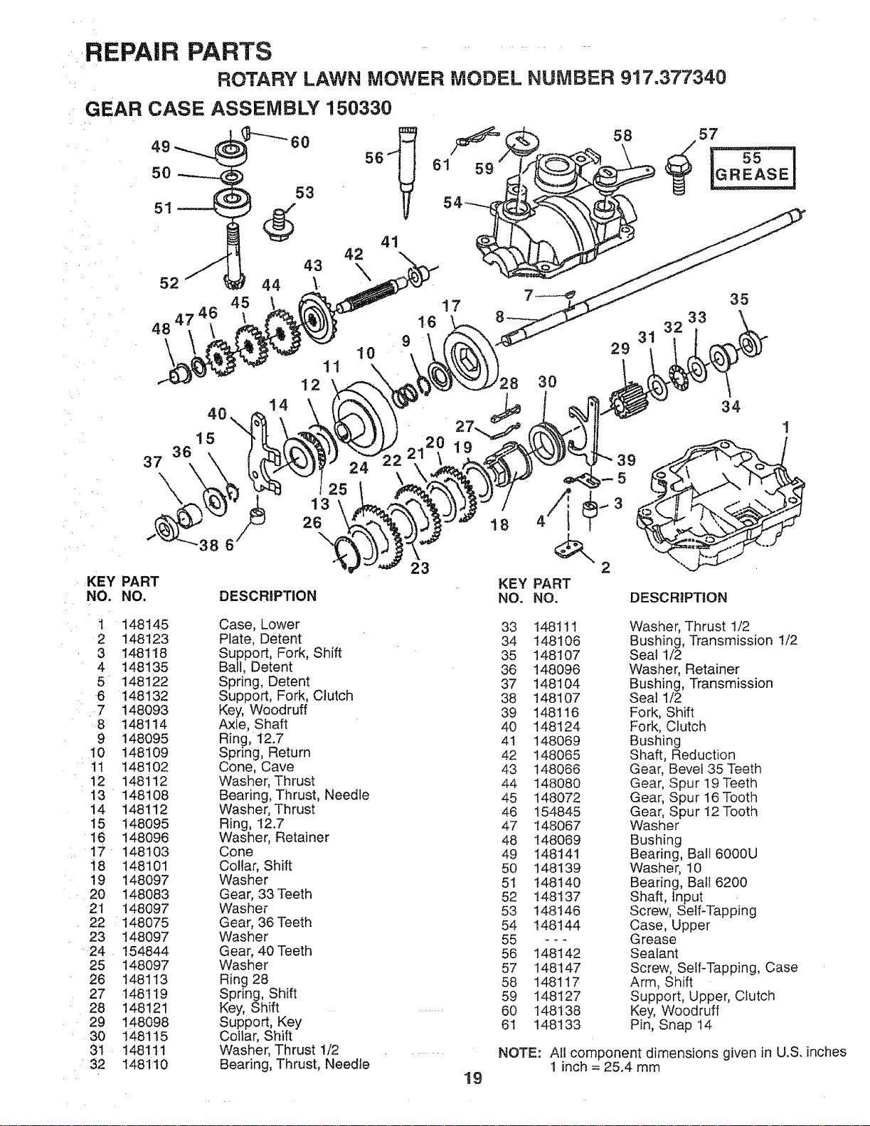
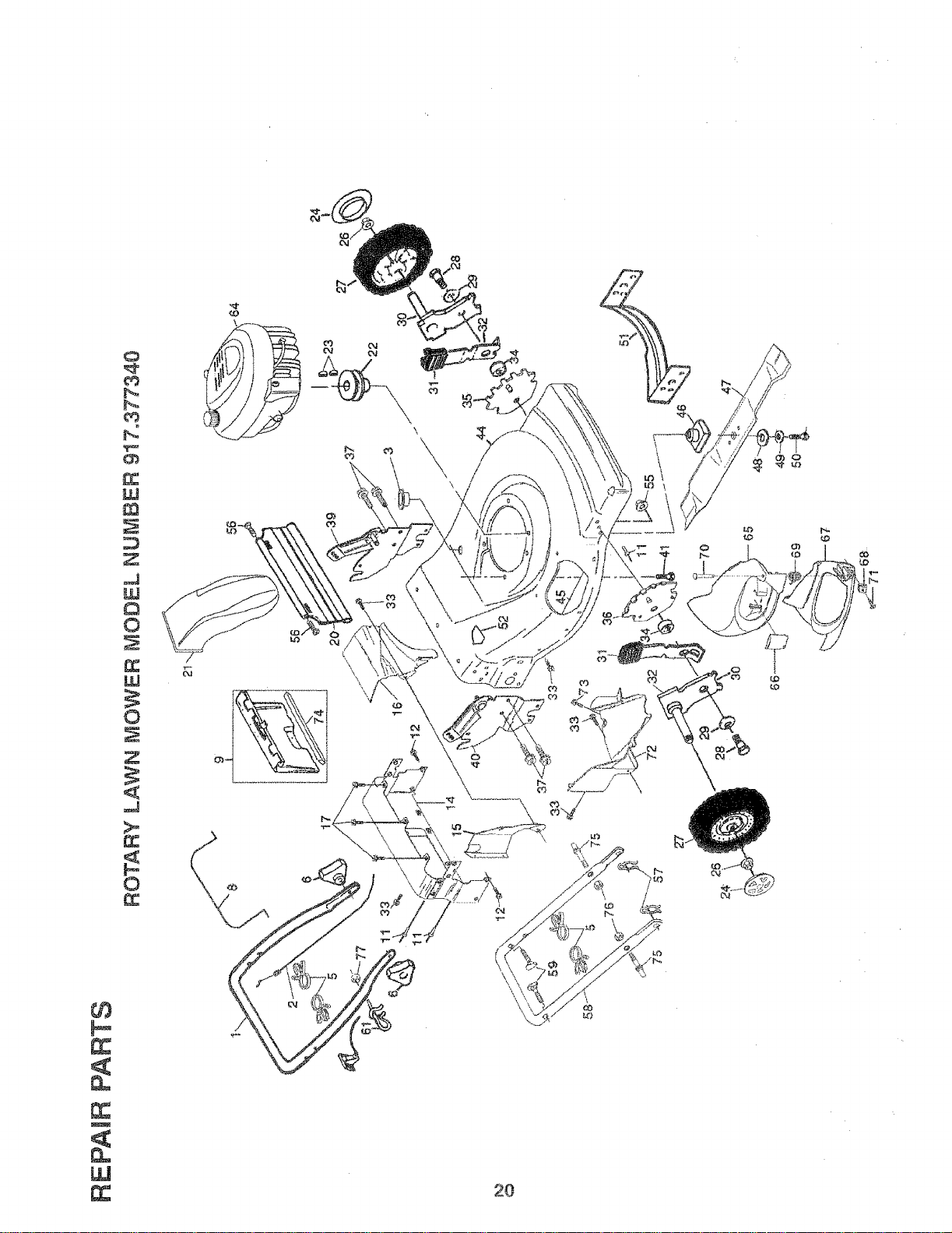
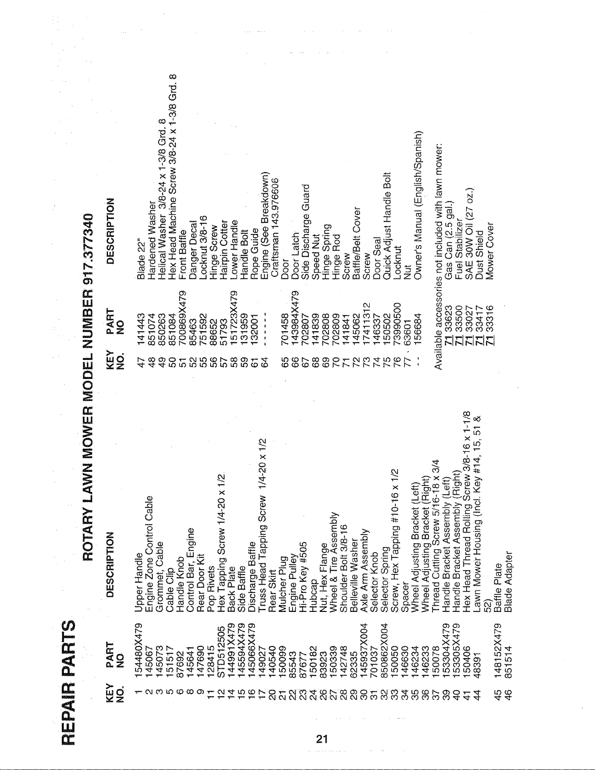
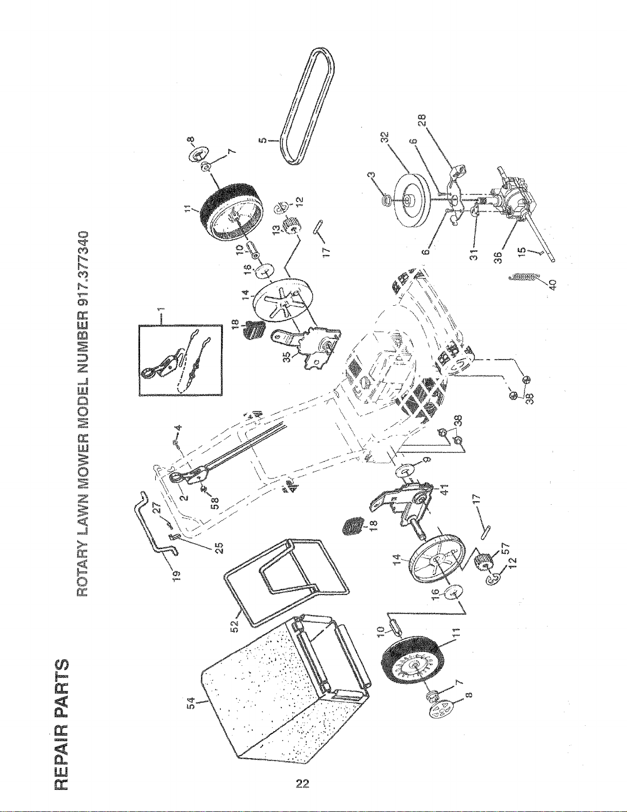
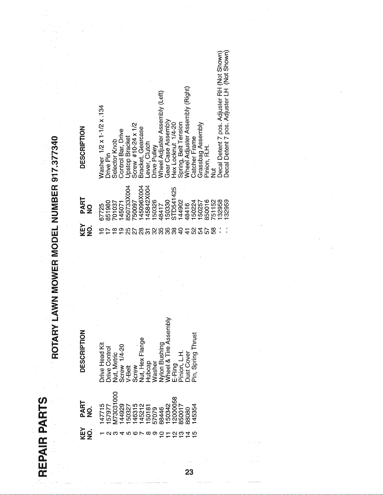
,REPAIR PARTS ............
ROTARY LAWN MOWER MODEL NUMBER 917.377340
GEAR CASE ASSEMBLY 150330
56 61 59
,)
43 42
44 \. X
45 17
1-6
9
10
37
4O
15
11
12
14
KEY PART
NO, NO.
25
13
26
DESCRIPTION
23
18
KEY
NO.
58
57
35
33
29 3'
30
34
1
PART
NO. DESCRIPTION
_2
3
4
5
6
7
8
9
10
i!
12
13
14
15
16
17
t8
19
2O
21
22
23
24
25
26
27
28
29
30
31
32
148145
148123
148118
148135
148122
148132
148093
148114
148095
148109
148102
148112
148108
148112
148095
148096
148103
148101
148097
148083
148097
148075
148097
154844
148O97
148113
148119
148121
148098
148115
148111
1481:10
Case, Lower
Plate, Detent
Support, Fork, Shift
Ball, Detent
Spring, Detent
Support, Fork, Clutch
Key, Woodruff
Axle, Shaft
Ring, 12.7
Spring, Return
Cone, Cave
Washer, Thrust
Bearing, Thrust, Needle
Washer, Thrust
Ring, !2.7
Washer, Retainer
Cone
Collar, Shift
Washer
Gear, 33 Teeth
Washer
Gear, 36 Teeth
Washer
Gear, 40 Teeth
Washer
Ring 28
Spring, Shift
Key, Shift
Support, Key
Coltar, Shift
Washer, Thrust 1/2
Bearing, Thrust, Needle
19
33 148111 Washer, Thrust 1/2
34 148106 Bushing, Transmission 1/2
35 148107 Seal 1/2
36 148096 Washer, Retainer
37 148104 Bushing, Transmission
38 148107 Seat 1/2
39 148116 Fork, Shift
40 148124 Fork, Clutch
4t 148069 Bushing
42 148065 Shaft, Reduction
43 148066 Gear, Bevel 35 Teeth
44 148080 Gear, Spur 19 Teeth
45 148072 Gear, Spur 16Tooth
46 !54845 Gear, Spur I2 Tooth
47 148067 Washer
48 148069 Bushing
49 148141 Bearing, Bail 6000U
50 148139 Washer, t0
51 t48140 Bearing, Ball 6200
52 148137 Shaft, Input
53 148146 Screw, Self-Tapping
54 148144 Case, Upper
55 - - - Grease
56 148142 Sealant
57 148147 Screw, Self-Tapping, Case
58 148117 Arm, Shift
59 148127 Support, Upper, Clutch
60 148138 Key, Woodruff
61 148133 Pin, Snap t4
NOTE: All component dimensions given in U.S, inches
1 inch = 25,4 mm
m
W
0
P_
_4
W
Z
J
U,t
0
W
0
d
0
\
\
\
\
\
\
o
\
2O
0
oO
J
G_
LL!
Z
--1
W
0
IJ.i
.I
>.
G:
I-
m
Z
o
t-
D_
0
z
o
G.
0
<o
co
0
co_
_×
i
J XDCO
O0
c
o ._
• 2
×
_ o
X o
_0_00_ _'_00_
O_O_O0_b__
_J
(D
0
E
.._ ..-_, o
.-=L_N _o00 •
_ o
_oLOu- i_
o
o
o9
_ 0,.I 0 04 "r'-
_0_
0
>
21
i
W
_Z
0
b_
W
r_
z
d
W
C_
©
W
©
Z
_Z
©
f_
\
\
l
22
0
0_
m
W
0
LU
Z
d
n_
0
m
I-
0
O0
W
Q
_0
n_z
wd
_Z
o
0
O0
0
_J
v
x _ o__ _ _-
_ 0
000_o
v
E < <
r.,. 0.)
y.o_ "_ _
=_ e •
_ ,.,_ -,'0 LI. 0'_ ,,,,,., m d_
E0O_oOnZnO
OO
___ 0__
_ 00_
_o_____
___0__ _ _
E
o
• _0 2
t_ _ z _ > r,,oz "r" _: uJ
¢0
I-
1,1.1
0
o ¸
o
___0 O_
_0_00_ 000_
23
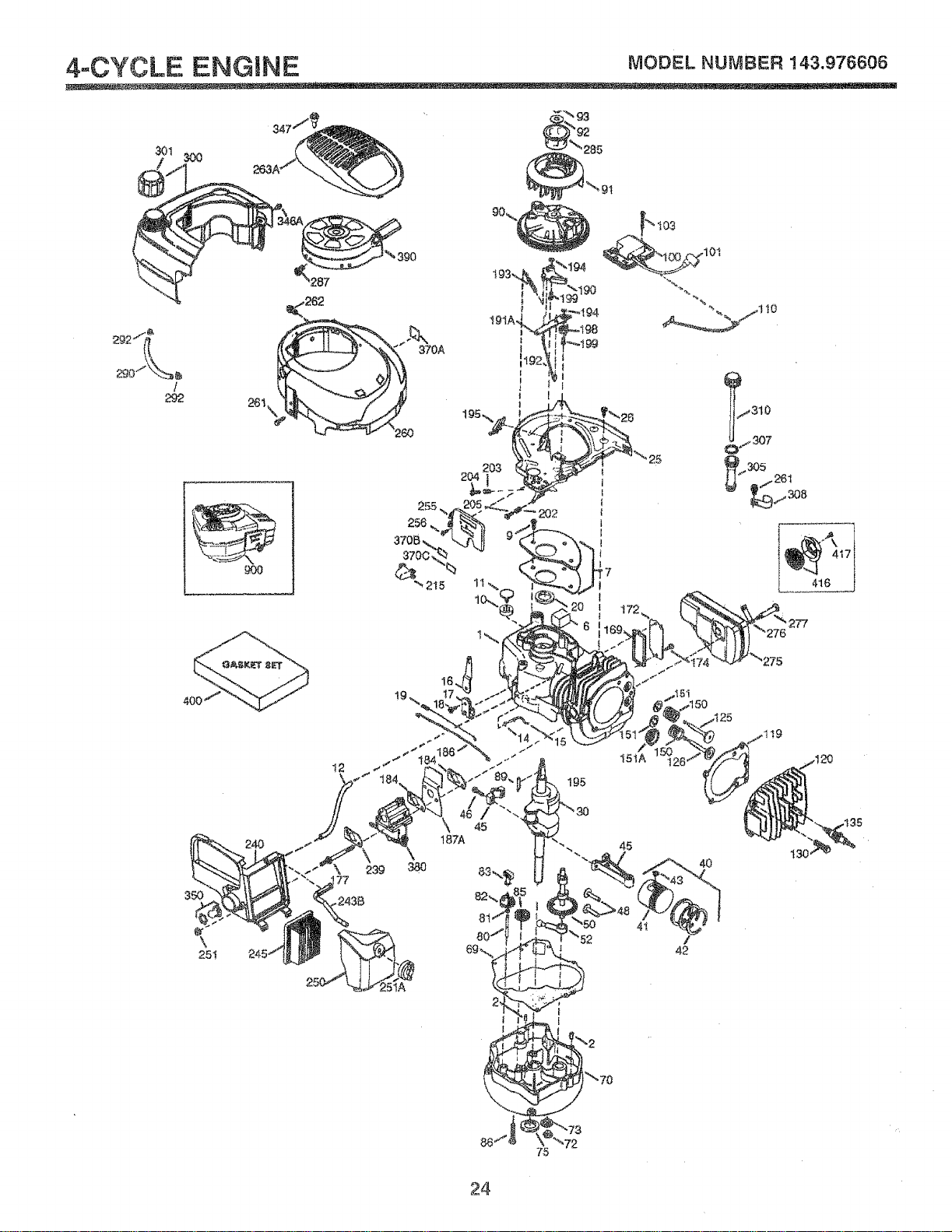
4-.CYCLE ENGINE MODEL NUMBER !43.976606
% 390
!
292
98
t
|
110
417
416
I2
195
!5tA
350
\
251
240
187A
45
24
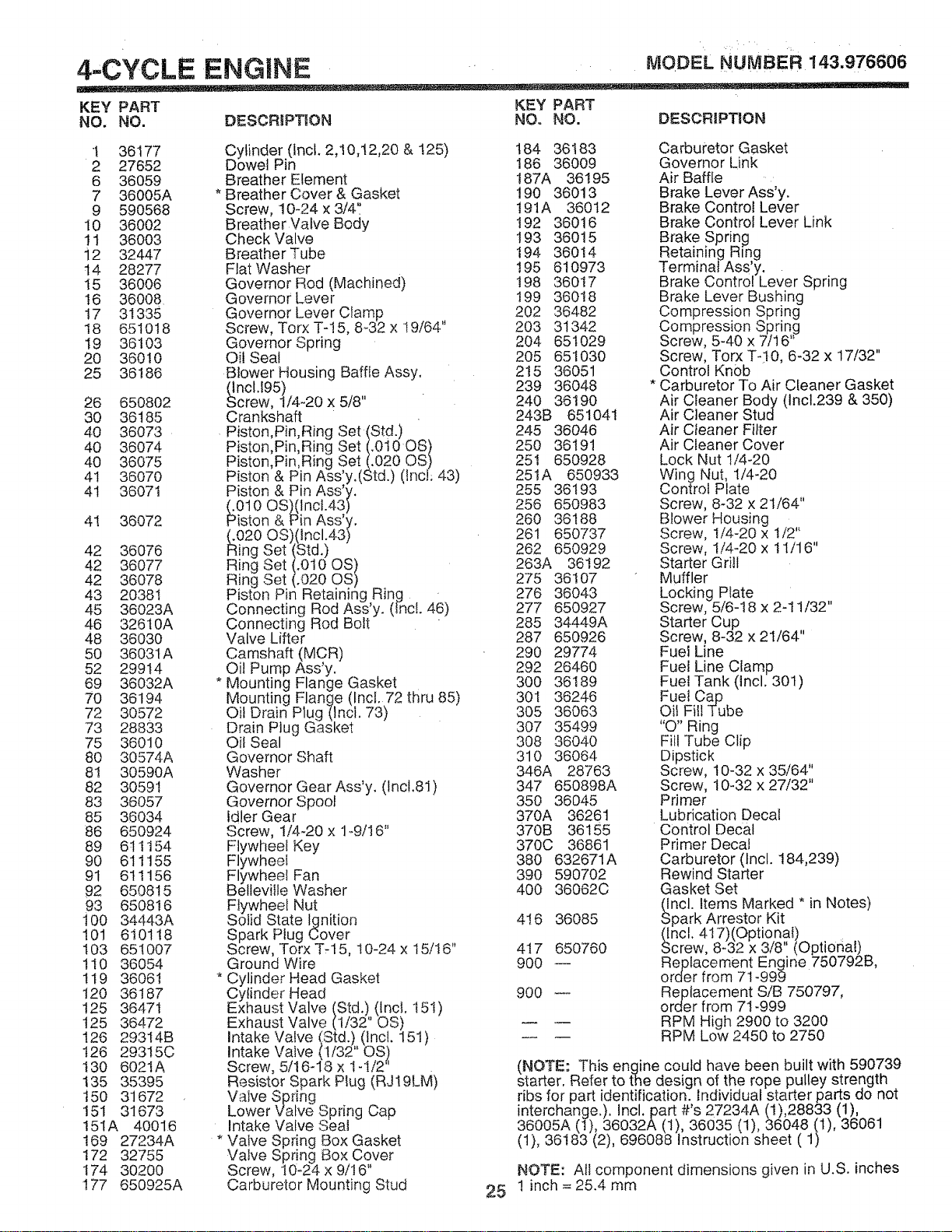
4-.CYCLE ENGnNE ' MODELNUMBER 143.976606
KEY PART KEY PART
NO. NO. DESCRIPTION NO. NO. DESCRIPTION
1 36177
2 27652
6 36059
7 36005A
9 590568
10 36002
11 36003
i2 32447
t4 28277
15 36006
16 36008
17 31335
18 651018
19 36103
20 36010
25 36186
26 650802
30 36185
40 36073
40 36074
40 36075
41 36070
41 36071
4I 36072
42 36076
42 36077
42 36078
43 20381
45 36023A
46 326t0A
48 36030
50 36031A
52 29914
69 36032A
70 36194
72 30572
73 28833
75 36010
8O 30574A
81 30590A
82 30591
83 36057
85 36034
86 650924
89 611154
90 611155
9t 611156
92 650815
93 650816
100 34443A
101 610118
t03 651007
110 36054
tt9 36061
120 36187
125 36471
t25 36472
126 293t4B
t26 293!5C
!30 6021A
135 35395
t50 31672
151 31673
15tA 4O016
169 27234A
172 32755
I74 30200
177 650925A
Cylinder (incl. 2,10,!2,20 & t 25)
Dowet Pin
Breather Element
* Breather Cover & Gasket
Screw, 10-24 x 3/4'i
Breather Valve Body
Check Valve
Breather Tube
Flat Washer
Governor Rod (Machined)
Governor Lever
Governor Lever Clamp
Screw, Torx T-15, 8-_32x 19/64"
Governor Spring
Oil Seal
Blower Housing Baffle Assy.
(1nc1.I95)
Screw, 1/4-.20 x 5/8"
Crankshaft
Piston,Pin,Ring Set (Std.)
Piston,Pin,Ring Set 00i0OS)
Piston,Pin,Ring Set (.020 OS)
Piston & Pin Ass'y.(Std.) (lncJ;43)
Piston & Pin Ass'v.
(.010 OS)(I ncI.43)
Piston & Pin Ass y.
(.020 OS)(incl.43)
Ring Set (Std.)
Ring Set (.010 OS)
Ring Set (.020 OS)
Piston Pin Retaining Ring •
Connecting Rod Ass y. (incL 46)
Connecting Rod Bolt
Valve Lifter
Camshaft (MCR)
Oil Pump Ass'y,
* Mounting Flange Gasket
Mounting Flange (Incl. 72 thru 85)
Oil Drair_ Plug (Incl. 73)
Drain Plug Gask.et
Oil Seal
Governor Shaft
Washer
Governor Gear Ass'y. (Inc!.81)
Governor Spoof
Idler Gear
Screw, 1/4-20 x 1-9/I6"
Flywheel Key
Flywheel
Flywheel Fan
Belleville Washer
Flywheel Nut
Solid State Ignition
Spark Plug Cover
Screw, Torx T-15, 10-24 x 15/16"
Ground Wire
* Cylinder Head Gasket
Cytinder Head
Exhaust Valve (Std.) (Inci. t 5!)
Exhaust Valve (1/32" OS)
I '-'
ntake Valve (_td.) (inc!. 151)
ntake Valve (t/32 OSt
Screw, 5/16q8 x I-!/2
Resistor Spark Plug (RJ19LM)
Valve Spring
Lower Valve Spring Cap
Intake Valve Seat
*V
aIve Spnng Box Gasket
Valve Spring Box Cover
,Screw, 10-24 x 9/16'
Carburetor Mounting Stud
25
184 36183 Carburetor Gasket
186 36009 Governor Link
187A 36195 Air Baffle
190 36013 Brake Lever Ass'y.
191A 36012 Brake Control Lever
192 36016 Brake Control Lever Link
193 36015 Brake Spring
194 36014 Retaining Ring
!95 610973 Terminal Ass'y.
198 36017 Brake Control Lever Spring
199 36018 Brake Lever Bushing
202 36482 Compression Spring
203 31342 Compression Spring
204 651029 Screw, 5-40 x 7/16
205 651030 Screw, Torx T-:t0, 6-32 x 17/32"
215 36051 Control Knob
239 36048 * Carburetor To Air Cleaner Gasket
240 36190 Air Cteaner Body (Incl.239 & 350)
243B 651041 Air Cleaner Stud
245 36046 Air Cleaner Filter
250 36191 Air Cleaner Cover
251 650928 Lock Nut 1/4-20
251A 650933 Wing Nut, I/4-20
255 36193 Control Plate
256 650983 Screw, 8-32 x 21/64"
260 36188 Blower Housing
261 650737 Screw, 1/4-20 x t/2"
262 650929 Screw, 1/4-20 x 11/16"
263A 36192 Starter Grill
275 36107 Muffler
276 36043 Locking Plate
277 650927 Screw, 5/6-18 x 2-11/32"
285 34449A Starter Cup
"p.
287 650926 S_rew, 8-32 x 21/64"
290 29774 Fuei Line
292 26460 Fuel Line Clamp
300 36189 Fue! Tank (Incl. 30t)
301 36246 Fuel Cap
305 36063 Oil FillTube
307 35499 "O" Ring
308 36040 FiLlTube Clip
310 36064 Dipstick
346A 28763 Screw, 10-32 x 35/64"
347 650898A Screw, 10-32 x 27/32"
350 36045 Primer
370A 36261 Lubrication Decal
370B 36155 Control Decal
370C 36861 Primer Decal
380 632671A Carburetor (Incl. 184,239)
390 590702 Rewind Starter
400 36062C Gasket Set
(Incl. Items Marked * in Notes)
416 36085 Spark Arrestor Kit
(Incl. 417)(OptionaI)
417 650760 Screw, 8-32 x 3/8 (Optional)
900 -- Replacement Engine 750792B,
order from 71-999
900 -- Replacement SiB 750797,
order from 71-999
RPM High 2900 to 3200
RPM Low 2450 to 2750
(NOTE: This engine could have been built with 590739
starter. Refer to (he design of the rope pulley strength
ribs for part identification., Individual starter parts do not
3nt_5h,_,r_tg_"_6J_3LAPlf) #3s6272_It (316)_2888_1_,(1_061
(t), 36183 (2), 696088 Instruction sheet (1)
NOTE: All component dimensions given in U.S. inches
1 inch = 25.4 rnm
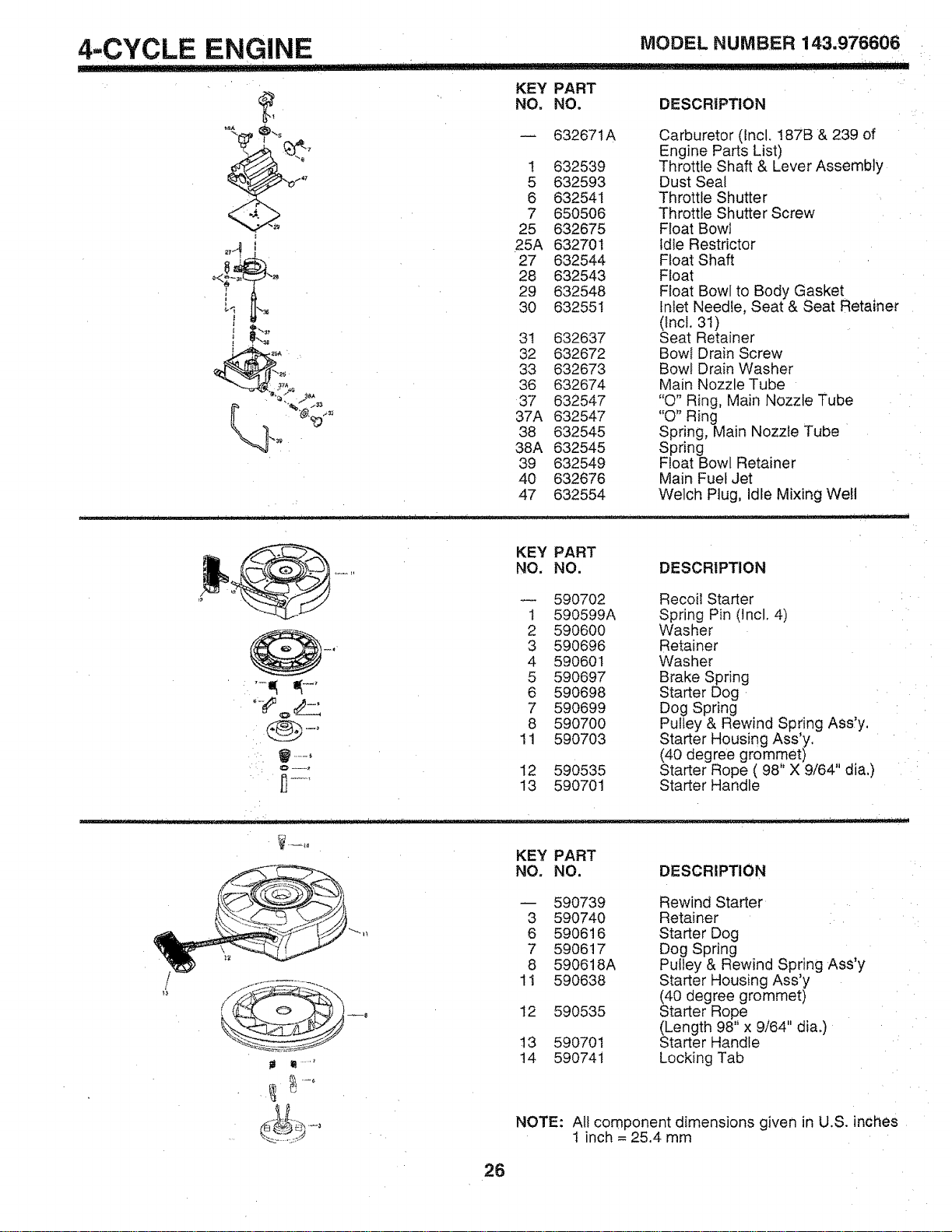
4-CYCLE ENGINE MODEL NUMBER 143,976606
........................................ i1_,i
/47
37A
740
KEY PART
NO, NO. DESCRIPTION
-- 632671A Carburetor (Incl. 187B & 239 of
Engine Parts List)
I 632539 Throttle Shaft & Lever Assembly
5 632593 Dust Seal
6 632541 Throttle Shutter
7 650506 Throttle Shutter Screw
25 632675 Float Bowl
25A 632701 Idle Restrictor
27 632544 Float Shaft
28 632543 Float
29 632548 Float Bowl to Body Gasket
30 632551 Inlet Needle, Seat & Seat Retainer
(incl. 31)
3I 632637 Seat Retainer
32 632672 Bowt Drain Screw
33 632673 Bowl Drain Washer
36 632674 Main Nozzle Tube
37 632547 "Q" Ring, Main Nozzle Tube
37A 632547 "Q" Ring
38 632545 Spring, Main Nozzle Tube
38A 632545 Spring
39 632549 Float Bowl Retainer
40 632676 Main Fuel Jet
47 632554 Welch Plug, Idle Mixing Well
KEY PART
NO. NO. DESCRIPTION
590702 Recoil Starter
1 590599A Spring Pin (tncl. 4)
2 590600 Washer
-, 3 590696 Retainer
4 590601 Washer
5 590697 Brake Spring
"-_ _--' 6 590698 Starter Dog
_ 7 590699 Dog Spring
8 590700 Pulley & Rewind Spring Ass'y.
11 590703
Starter Housing Ass'y,
...... (40 degree grommet) ,,
'='--' 12 590535 Starter Rope ( 98 X 9/64 dia.)
j_' 13 590701 Starter Handle
KEY PART
NO. NO. DESCRIPTION
590739 Rewind Starter
3 590740 Retainer
6 590616 Starter Dog
7 590617 Dog Spring
8 590618A Pulley & Rewind Spring AsS'y
11 590638 Starter Housing Ass'y
(40 degree grommet)
12 590535 Starter Rope
(Length 98" x 9/64" dia.)
t3 590701 Starter Handle
t4 59074t Locking Tab
NOTE: Al! component dimensions given in U.S. inches
1 inch = 25.4 mm
26

SERV!CE NOTES
27
OWNER'
MANUAL
MODEL NO.
917.377340
IF YOU NEED
REPAIR SERVICE
OR PARTS:
FOR REPAIR SERVICE, CALL
THIS TOLL FREE NUMBER:
1-800-4-REPAIR
(1-800_473W247)
FOR REPLACEMENT PARTS
INFORMATION AND
ORDERING, CALL THIS
TOLL FREE NUMBER:
1-800-.FON-PART
(1-800-366-7278)
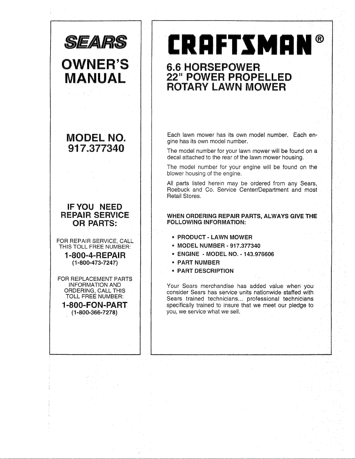
£RAFTSMaN®
6.6 HORSEPOWER
22" POWER PROPELLED
ROTARY LAWN MOWER
Each lawn mower has its own model number, Each en-
gine has its own model number,
The modet number for your lawn mower wi!! be found on a
decal attached to the rear of the Sawnmower housing.
The model number for your engine will be found on the
blower housing of the engine.
All parts listed herein may be ordered from any Sears,
Roebuck and Co. Service Center/Department and most
Retail Stores.
WHEN ORDERING REPAIR PARTS, ALWAYS GIVE THE
FOLLOWING INFORMATION:
° PRODUCT- LAWN MOWER
" MODEL NUMBER - 917.377340
• ENGINE - MODEL NO. - 143.976606
° PART NUMBER
• PART DESCRIPTION
Your Sears merchandise has added value when you
consider Sears has service units nationwide staffed with
Sears trained technicians.., professional technicians
specifically trained to insure that we meet our pledge to
you, we service what we sell.