Loading ...
Loading ...
Loading ...
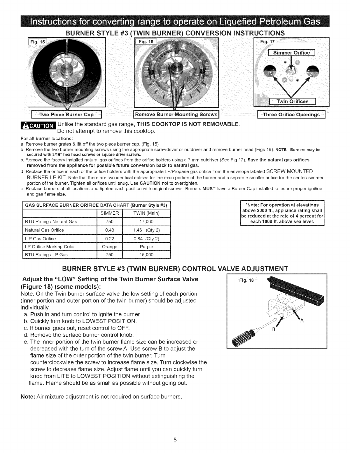
BURNER STYLE #3 (TWIN BURNER) CONVERSION INSTRUCTIONS
Two Piece Burner Cap I Remove Burner Mounting Screws
Unlike the standard gas range, THIS COOKTOP IS NOT REMOVABLE.
Do not attempt to remove this cooktop.
For all burner locations:
a. Remove burner grates &lift off the two piece burner cap. (Fig. 15)
Fig. 17
! Simmer Orifice
_win Orifices !
_Orifice Openings ]
b. Remove the two burner mounting screws using the appropriate screwdriver or nutdriver and remove burner head (Figs 16). NOTE- Burners may be
secured with 3/16" hex head screws or square drive screws,
c. Remove the factory installed natural gas orifices from the orifice holders using a 7 mm nutdriver (See Fig 17). Save the natural gas orifices
removed from the appliance for possible future conversion back to natural gas.
d. Replace the orifice in each of the orifice holders with the appropriate LP/Propane gas orifice from the envelope labeled SCREW MOUNTED
BURNER LP KIT. Note that there are two identical orifices for the main portion of the burner and a separate smaller orifice for the center/simmer
portion of the burner. Tighten all orifices until snug. Use CAUTION not to overtighten.
e. Replace burners at all locations and tighten each position with original screws. Burners MUST have a Burner Cap installed to insure proper ignition
and gas flame size.
GAS SURFACE BURNER ORIFICE DATA CHART (Burner Style #3)
SIMMER TWIN (Main)
BTU Rating / Natural Gas 750 17,000
Natural Gas Orifice 0.43 1.46 (Qty 2)
L P Gas Orifice 0.22 0.84 (Qty 2)
LP Orifice Marking Color Orange Purple
BTU Rating / LP Gas 750 15,000
*Note: For operation at elevations
above 2000 ft., appliance rating shall
be reduced at the rate of 4 percent for
each 1000 ft. above sea level.
BURNER STYLE #3 (TWIN BURNER) CONTROL VALVE ADJUSTMENT
Adjust the "LOW" Setting of the Twin Burner Surface Valve Fig. t8
(Figure 18) (some models):
Note: On the Twin burner surface valve the low setting of each portion
(inner portion and outer portion of the twin burner) should be adjusted
individually. _'_
a. Push in and turn control to ignite the burner ,_
b. Quickly turn knob to LOWEST POSITION.
c. If burner goes out, reset control to OFF.
d. Remove the surface burner control knob.
e. The inner portion of the twin burner flame size can be increased or
decreased with the turn of the screwA. Use screw B to adjust the
flame size of the outer portion of the twin burner. Turn
counterclockwise the screw to increase flame size. Turn clockwise the
screw to decrease flame size. Adjust flame until you can quickly turn
knob from LITE to LOWEST POSITION without extinguishing the
flame. Flame should be as small as possible without going out.
Note: Air mixture adjustment is not required on surface burners.
Loading ...
Loading ...
Loading ...