
Loading ...
Loading ...
Loading ...
,m
Maintenance(Continued)
WARNING
DONOTattempt anyadjustments, maintenance,service or
repairswith the engine running. STOPengine.STOPblade.
Engageparking brake. Removekey.Removespark plug
wire from spark plug and secureaway from plug. Engine
and components are HOT.Avoid serious burns, allow all
parts to cool beforeworking on machine.FuelFillerCap
and vent must beclosed securelyto prevent fuel spillage.
MowerDriveBeltReplacement
Inspect the mower drive belt asdescribed in the section,
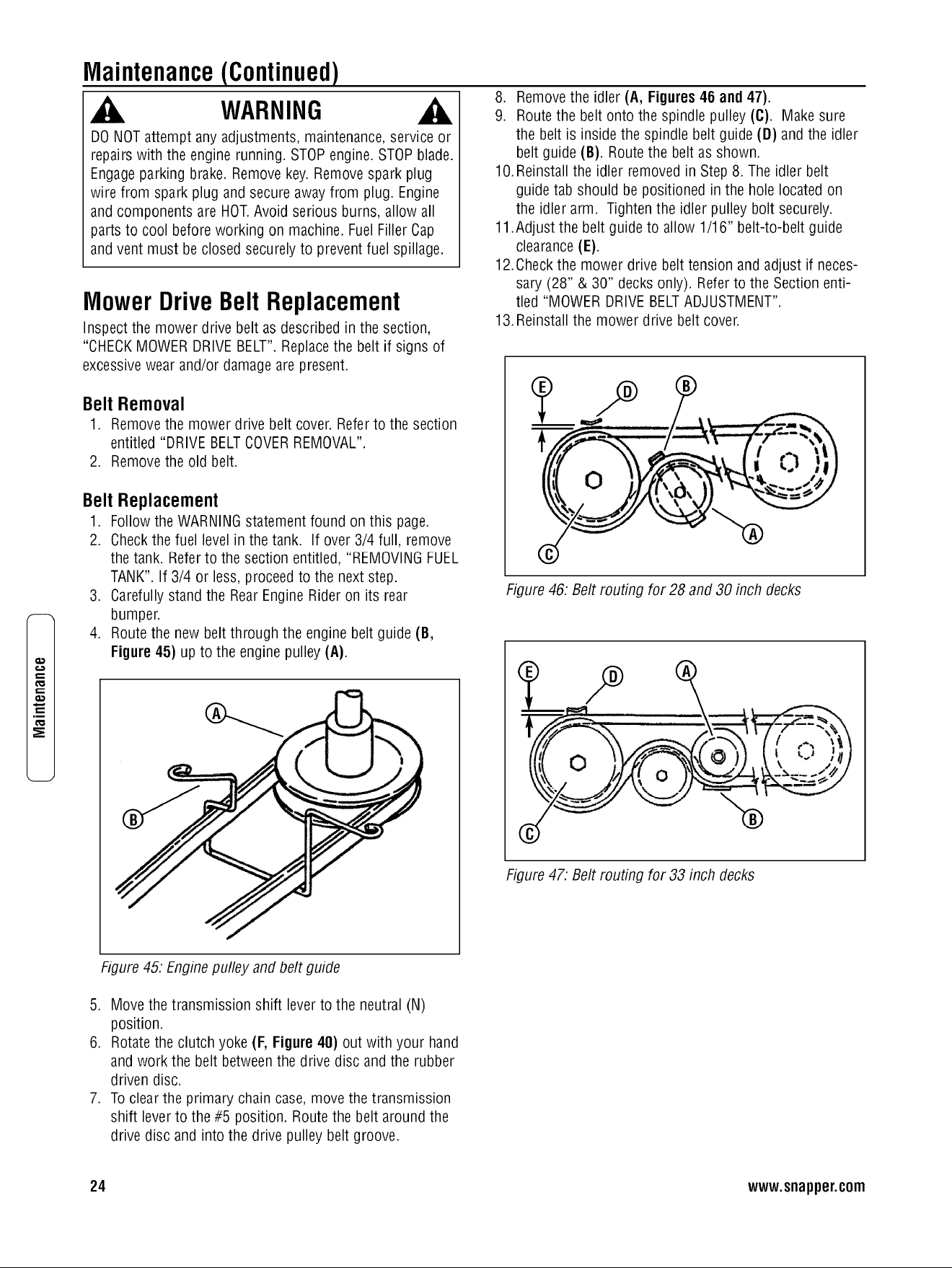
8. Removethe idler (A, Figures46 and 47).
9. Routethe belt onto the spindle pulley (C). Make sure
the belt is insidethe spindle belt guide (D) and the idler
belt guide (B). Routethe belt as shown.
lO.Reinstall the idler removed in Step8. The idler belt
guide tab should be positioned in the hole located on
the idler arm. Tighten the idler pulley bolt securely.
11.Adjust the belt guide to allow 1/16" belt-to-belt guide
clearance(E).
12.Checkthe mower drive belt tension and adjust if neces-
sary (28" & 30" decksonly). Referto the Section enti-
tled "MOWER DRIVEBELTADJUSTMENT".
13.Reinstallthe mower drive belt cover.
"CHECKMOWERDRIVEBELT".Replacethe belt if signs of
excessivewear and/or damageare present.
Belt Removal
1. Removethe mower drive belt cover. Referto the section
entitled "DRIVEBELTCOVERREMOVAL".
2. Removethe old belt.
Belt Replacement
1. Followthe WARNINGstatementfound on this page.
2. Checkthe fuel levelin the tank. If over 3/4 full, remove
the tank. Referto the section entitled, "REMOVINGFUEL
TANK".If 3/4 or less, proceedto the next step.
©
3. Carefullystand the RearEngineRider on its rear
bumper.
4. Route the new belt through the engine belt guide (B,
Figure 45) up to the engine pulley (A).
Figure 46: Belt routing for 28 and 30 inch decks
t
Figure 47. Belt routing for 33 inch decks
Figure45. Enginepulley and belt guide
5. Movethe transmission shift leverto the neutral (N)
position.
6. Rotatethe clutch yoke (F, Figure 40) out with your hand
and work the belt betweenthe drive disc and the rubber
driven disc.
7. Toclearthe primary chain case,move the transmission
shift leverto the #5 position. Route the belt aroundthe
drive disc and into the drive pulley belt groove.
24 www.snapper.com
Loading ...
Loading ...
Loading ...