
Loading ...
Loading ...
Loading ...
Maintenance(Continued)
WARNING
DONOTattempt anyadjustments, maintenance,service or
repairswith the engine running. STOPengine.STOPblade.
Engageparking brake. Removekey.Removespark plug
wire from spark plug and secureaway from plug. Engine
and components are HOT.Avoid serious burns, allow all
parts to cool beforeworking on machine.FuelFillerCap
and vent must beclosed securelyto prevent fuel spillage.
.m
RearEngineRiderDrive
Components
Your Snapper rider is equipped with a patentedsmooth start
clutch. Theclutch should operatesmoothly and provide
ampletraction. If problems are experienced,contact your
Snapper dealerfor repair.
ServiceBrake/ ParkBrakeAdjustment
Testthe wheel brake on a dry concrete surface. When prop-
erly adjusted,the RearEngine Riderwill stop within 5 feet
from fastest speed. If stopping distance is more than 5 feet,
the wheel brakeshould be adjusted asfollows:
1. Followthe WARNINGstatementfound on this page.
2. Checkthe fuel levelin tank. If over3/4 full, removetank.
Refer to the section entitled "REMOVINGTHEFUEL
TANK". If 3/4 or less, proceedto the next step.
3. Carefullystand the RearEngineRider on its rear
bumper.
4. Depressthe clutch/brake pedal (A, Figure39) all the
way down. Move and hold the park brakelever (B) in
the "ON" position and releasethe clutch/brake pedal to
set the park brake.
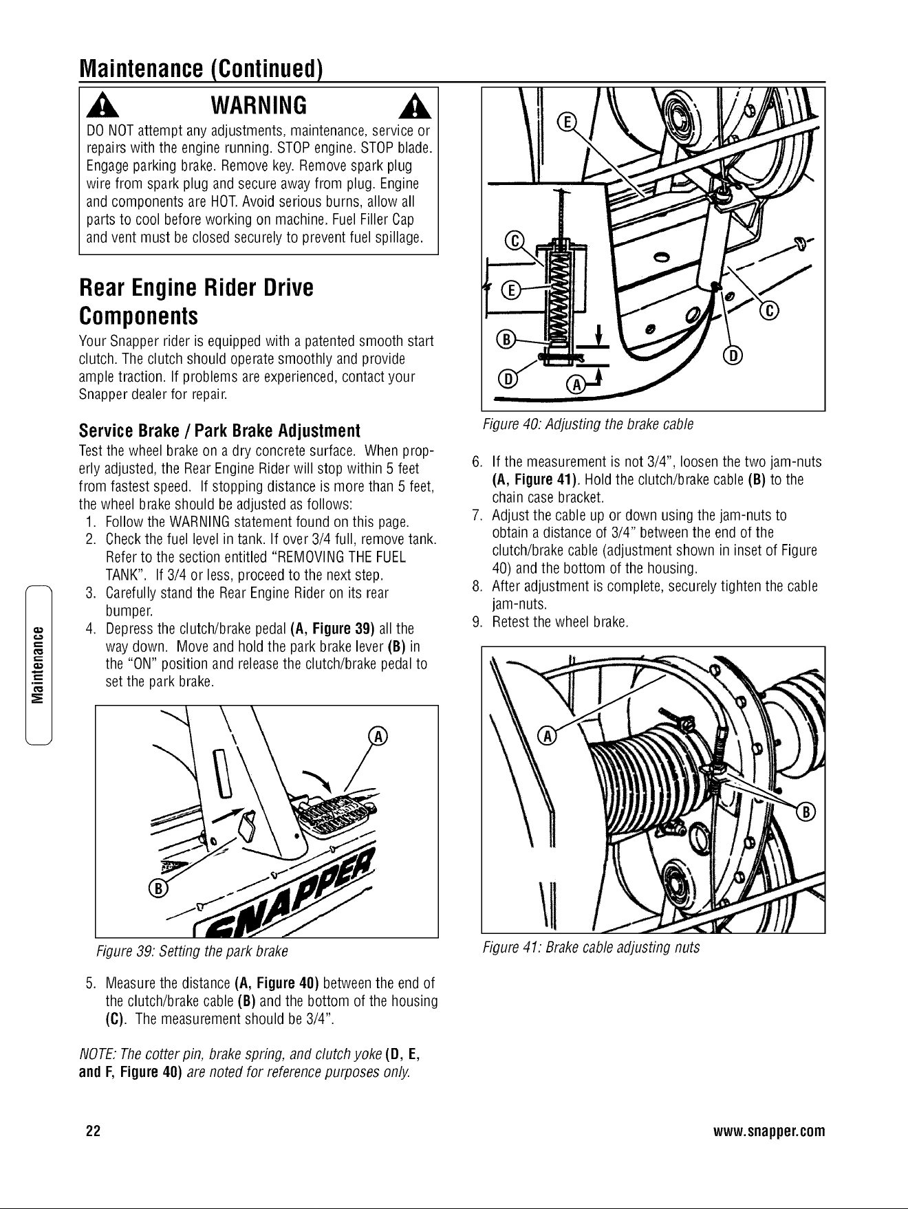
Figure 40:Adjusting the brakecable
6. If the measurement is not 3/4", loosenthe two jam-nuts
(A, Figure41). Holdthe clutch/brakecable (B) to the
chain case bracket.
7. Adjust the cableup or down using the jam-nuts to
obtain a distance of 3/4" betweenthe end of the
clutch/brake cable (adjustment shown in inset of Figure
40) and the bottom of the housing.
8. After adjustment is complete, securelytighten the cable
jam-nuts.
9. Retestthe wheel brake.
Figure39: Setting thepark brake
5. Measurethe distance(A, Figure40) betweenthe end of
the clutch/brake cable(B) and the bottom of the housing
(C). The measurementshould be 3/4".
NOTE:Thecotter pin, brakespring, and clutch yoke (D, E,
and F, Figure40) are noted for referencepurposes only.
Figure 41: Brakecableadjusting nuts
22 www.snapper.com
Loading ...
Loading ...
Loading ...