Loading ...
Loading ...
Loading ...
C.MAKE ELECTRICAL
CONNECTION
It is your responsibility:
• To contact a qualified electrical installer.
• To assure that the electrical installation
is adequate and in conformance with
the National Electrical Code, ANSI/
NFPA 70-latest edition and all local
codes and ordinances.
Copies of the code standards listed
above may be obtained from:
National Fire Protection Association
Batterymarch Park
Quincy, Massachusetts 02269
ELECTRICAL REQUIREMENTS
The proper electrical connection
ensures a safe installation that
meets local code requirements,
A three-wire or four-wire, single
phase 120/240-volt, 60-Hz., AC-only,
electrical supply (or three-wire or
four-wire, 120/208-volt if specified on
serial/rating plate) is required on a
separate 30-ampere circuit, fused on
both sides of the line. A time-delay fuse
or circuit breaker is recommended.
This dryer is manufactured with the
3-wire, frame-grounding conductor
connected to the NEUTRAL (center)
of the wiring harness of the terminal
block. Do not have a fuse in the
neutral or grounding circuit. A fuse
in the neutral or grounding circuit
could result in an electrical shock.
Use a 4-conductor cord when the
dryer is installed in a mobile home or
an area where local codes do not
permit grounding through the neutral.
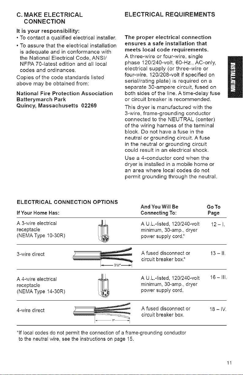
ELECTRICAL CONNECTION OPTIONS
If Your Home Has:
A 3-wire electrical
receptacle
(NEMA Type 10-30R)
And You Will Be Go To
Connecting To: Page
A U.L.-tisted, 120/240-volt
minimum, 30-amp., dryer
power supply cord.*
12-1.
3-wire direct A fused disconnect or 13 - II.
circuit breaker box*
A 4-wire electrical
receptacle
(NEMA Type 14-30R)
A U.L.-tisted, 120/240-volt
minimum, 30-amp., dryer
power supply cord.
16- III.
4-wire direct A fused disconnect or 18 - IV.
circuit breaker box.
*If local codes do not permit the connection of a frame-grounding conductor
to the neutral wire, see the instructions on page 15.
I1
Loading ...
Loading ...
Loading ...