Loading ...
Loading ...
Loading ...
1 Product Introduction D-Link Smart Managed Switch User Manual
4
Rear Panel
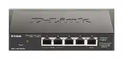
Figure 1.4 – DGS-1100-05PD Rear Panel
Power: Use RJ45 to connect the PD port (port 5) and Power over Ethernet Adapter Kit.
Kensington Lock: This is used to attach a physical Kensington security lock.
GND: This is used to connect the Switch to ground.
NOTE: The power budget is 18 Watts with 802.3at and 8 Watts with
802.3af for DGS-1100-05PD.
DGS-1100-08
8-Port 10/100/1000Mbps Smart Managed Switch.
Front Panel
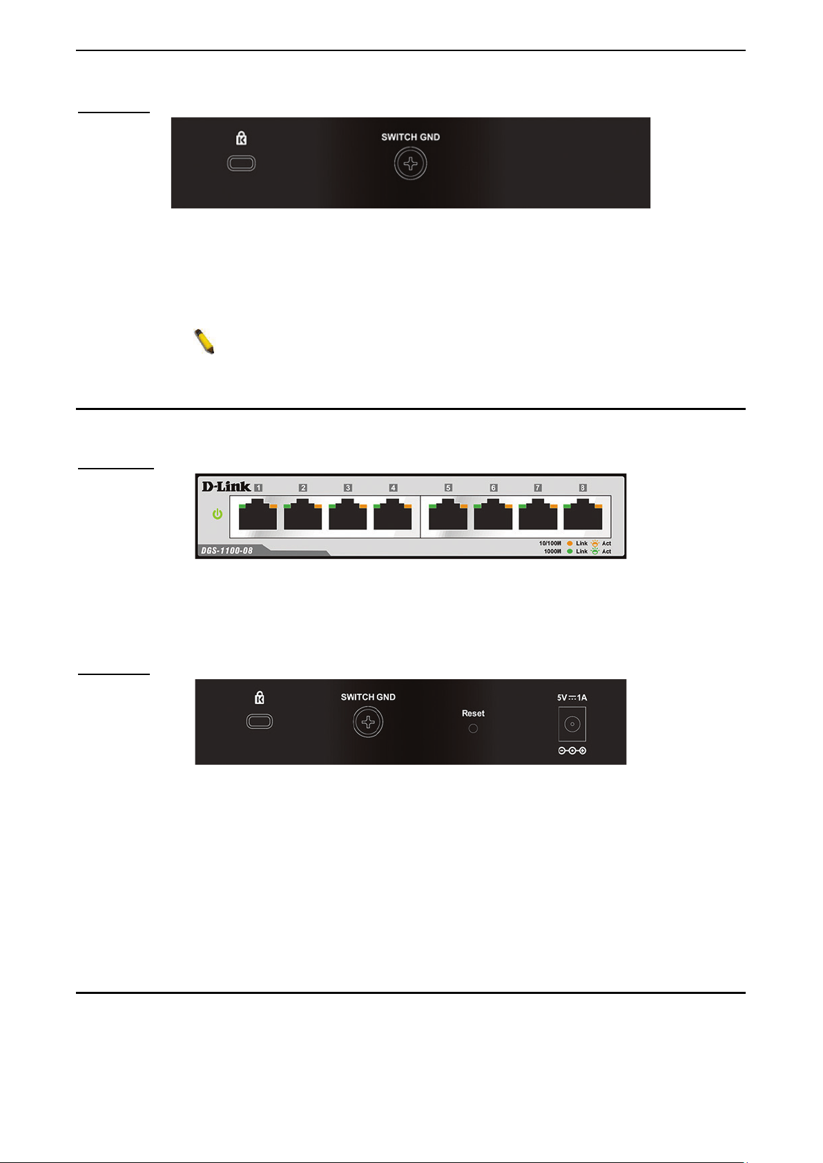
Figure 1.5 – DGS-1100-08 Front Panel
Power LED: The Power LED lights up when the Switch is connected to a power source.
Link/Act/Speed LED (Ports 1-8): 10/100/1000 Mbps ports to connect Ethernet devices to the switch.
Rear Panel
Figure 1.6 – DGS-1100-08 Rear Panel
Power: Input for a 5V/1A AC adapter.
Reset: Press the Reset button for 1 to 5 seconds to reboot the Switch. Press the Reset button for 6 to10
seconds to reset the Switch back to the default settings. The LED will light up solid amber for 2 seconds.
When pressing the Reset button for longer than 10 seconds, the device will enter loader mode and the LED
will light up solid green for 2 seconds. If the device cannot reboot, it will automatically enter loader mode.
Alternatively, you can press Reset to power up the device and enter loader mode.
Kensington Lock: This is used to attach a physical Kensington security lock.
GND: This is used to connect the Switch to ground.
DGS-1100-08P
8-Port 10/100/1000Mbps PoE Smart Managed Switch.
Loading ...
Loading ...
Loading ...