Loading ...
Loading ...
Loading ...
1 Product Introduction D-Link Smart Managed Switch User Manual
6
NOTE: The power budget is 64 Watts for DGS-1100-08P.
LED Indicators
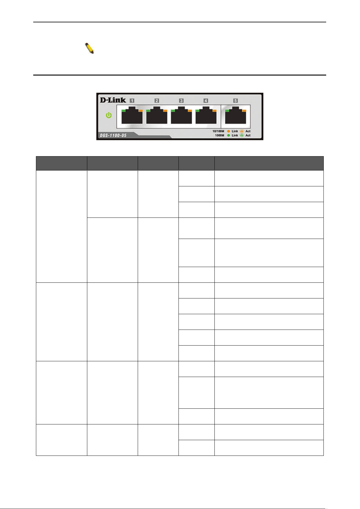
The Switches feature LED indicators for Power and Link/Act for each port. The following shows the LED
indicators for the DGS-1100-05/05PD/08/08PD switches along with an explanation of each indicator.
Figure 1.9 –LED Indicators on DGS-1100 series
Location Indicator LED Color Status Description
Per Device
Power Green
Solid Light The device is powered on.
Blinking
PoE Pass Through Off (DGS-1100-
05PD only)
Light off The device is powered off.
PoE Max.
(Only DGS-1100-
08P)
Red
Solid Light
When the power output to PDs is over
57W. No additional PDs can be
powered for safety consideration.
Blinking
If the user unplugged certain PDs and
made the PoE power budget left over
7W, the PoE MAX LED will blink 5
seconds.
Light off
When the power budget is using less
the 57W.
LED Per
10/100/1000
Mbps Port
Link/Act/Speed Green/Amber
Solid Green
Indicates there is a 1000 Mbps
connection on this port.
Blinking
Green
Indicates data is being processed on
this port at 1000 Mbps.
Solid Amber
Indicates there is a 10/100 Mbps
connection on this port.
Blinking
Amber
Indicates data is being processed on
this port at 10/100 Mbps.
Light off
Indicates there is no active link on this
port.
LED Per PoE Port
PoE Status Green/Amber
Solid Green PD device insert and power feeding.
Solid Amber
PD device insert but failure occurs.
(PSE can’
t provide power to PD due to
PD error or power budget is not
enough.)
Light off No PD device inserts.
LED Per PD Port
(DGS-1100-05PD
only)
PD Status Green/Amber
Solid Green Receiving power from PSE per 802.3at
Solid Amber
Receiving power from PSE per PSE.
Loading ...
Loading ...
Loading ...