Loading ...
Loading ...
Loading ...
13
Optional Equipment
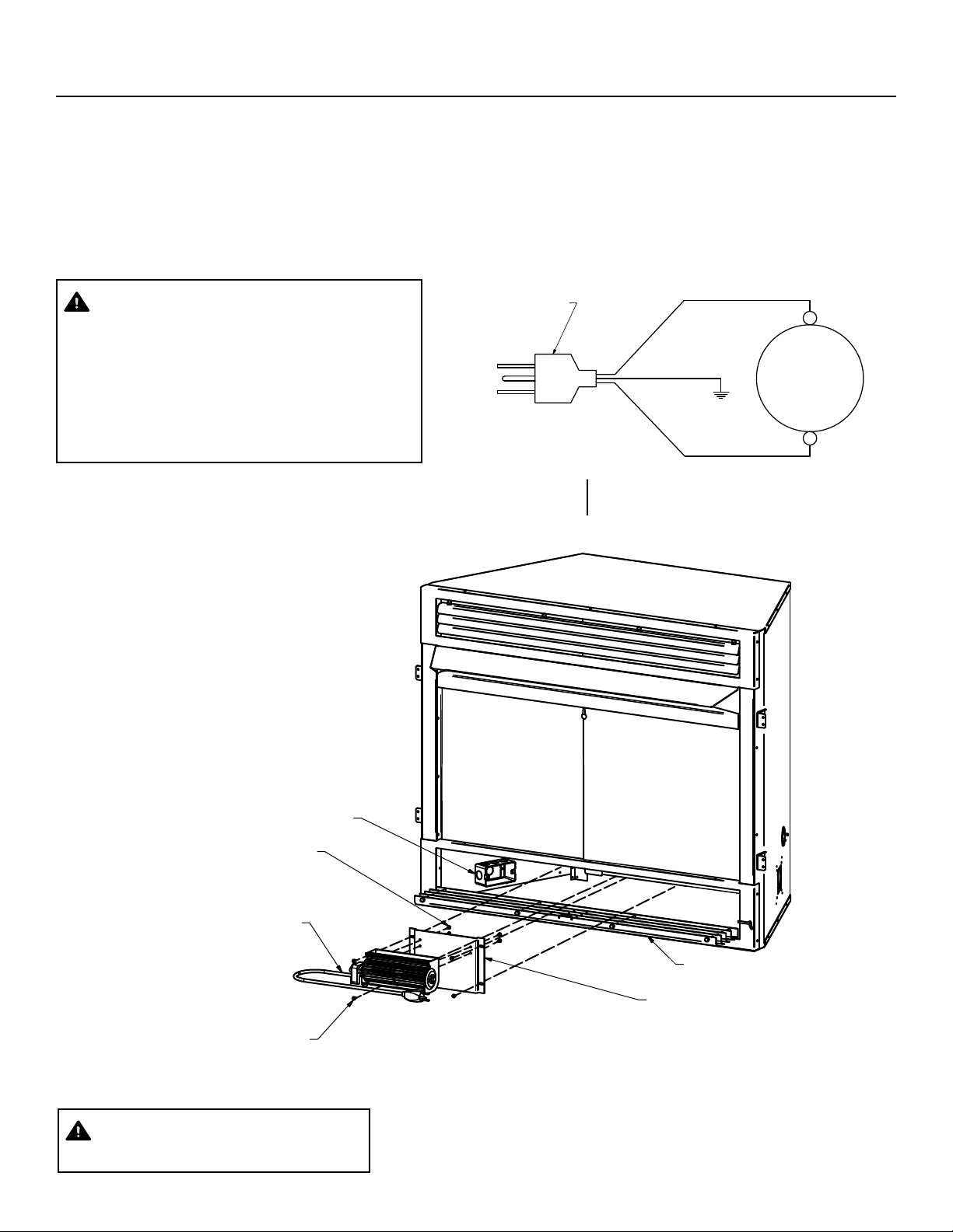
OPTIONAL BLOWER (ZCB100)
If you are installing the forced air kit on PHZC32C, PHZC36C, and PHZC42C models, see the installation instructions provided with the kit
for electrical wiring requirements, or the blower installation section. The rebox must be connected to main power supply at time of
rebox installation. The blower should be installed prior to the installation of the vent-free heater but can be installed after installation if the
electrical connections have already been installed. The electrical connections must be made before the rebox is framed and enclosed in
the nished walls.
WARNING!
Electrical connections should only be performed by a qual-
ied, licensed electrician, main power must be off when
connecting to
main electrical power supply or performing service.
The blower when installed, must be electrically grounded
in accordance with local codes or in the absence of local
codes, with the National Electrical Code ANSI/NFPA 70.
Fig. - Optional Blower Installation
Optional ZCB100 Blower Kit
Blower Mounting Bracket
Electrical Box
Lower Grill Assembly
(4) #8 Sheet Metal Screws
(4) Sheet Metal Screws
Included in Blower Kit
Figure 15 - Optional Blower Installation
Blower Installation Instructions:
1. Lower the bottom grill assembly and remove the
blower mounting bracket attached to the inner back
wall of the rebox with a #2 phillips screw driver.
2. Attach the blower to the bracket with the (4) sheet
metal screws included int he blower kit as shown in
Figure 15.
3. Re-install the bracket insuring the blower outlet is
pointed upward.
4. Plug in the cord to the properly grounded 3-prong
receptacle.
WARNING!
Never use an extension cord to power the blower.
1
1
2
2
A A
B B
ZCF-5060
GHP Group Inc.
6440 W Howard St., Niles, IL 60714
DRAWN
DanDowning
CHECKED
APPROVED
A
2/14/2018
SIZE
TITLE
REV
X.XXX = +/- 0.005"
X.XX = +/- 0.010"
X.X = +/-0.100"
ANGLES = +/- 2 Deg.
MATERIAL
DWG NO
SCALE
TOLERANCES
WIRING DIAGRAM
POWER CORD / CABLE DE ENERGIA
MOTOR / MOTOR
BLACK / NEGRO
GREEN / VERDE
WHITE / BLANCO
IF ANY ORIGINAL WIRING SUPPLIED
WITH THIS HEATER MUST BE REPLACED,
IT MUST BE TYPE AWG 105C WIRE OR ITS
EQUIVALENT EXCEPT AS INDICATED.
SI SE DEBE REEMPLAZAR UN CABLEADO
ORIGINAL PROVIEIDO CON EL CALENTADOR,
DEBE SER CABLE TIPO AWG 105C O SU
EQUIVALENTE, EXCEPTO SI SE INDICA DE
OTRA MANERA.
EARTH (SHELL)
TIERRA (CUBIERTA)
WIRING DIAGRAM
ZCF FIREBOX BLOWER
Loading ...
Loading ...
Loading ...