Loading ...
Loading ...
Loading ...
74
MULTI F / MULTI F MAX Outdoor Unit Installation Manual
Due to our policy of continuous product innovation, some specifications may change without notification.
©LG Electronics U.S.A., Inc., Englewood Cliffs, NJ. All rights reserved. “LG” is a registered trademark of LG Corp.
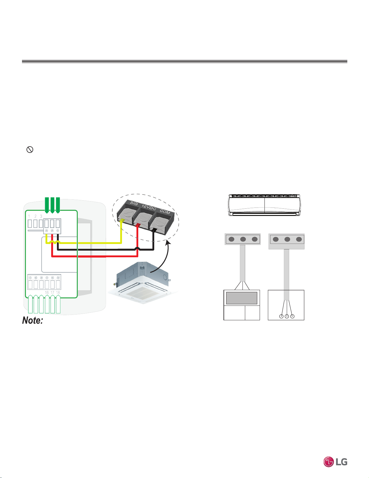
From Indoor Units to Remote Controllers
• Communication cable from indoor unit to remote controller(s) is to be LG supplied or field supplied 22 AWG, 3-conductor, twisted, stranded,
unshielded. Wiring must comply with all applicable local and national codes.
• ,IXVLQJWKH/*VXSSOLHGFDEOHDQGWKHOHQJWKQHHGVWREHH[WHQGHGWKH/*([WHQVLRQ.LWVROGVHSDUDWHO\PXVWEHXVHG$PD[LPXPRI
four (4) kits (up to 165 feet) can be used.
• Remote controllers have hardwired connections: SIG - 12V - GND (Comm.) terminals.
• Indoor unit controller connections depend on type of indoor unit being installed. Some indoor units use terminal block connections; other
indoor units use Molex connections. See diagrams below for the two options. Refer to the wiring diagram schematic found in the indoor unit
itself, or to the indoor unit wiring diagrams in the Engineering Manuals for more information.
•
NEVER splice, cut, or extend LG supplied cable with field provided cable. Always include enough cable to cover distance between the
indoor unit and the remote controller.
• Set the indoor unit operating parameters using DIP switches, or by setting up the remote controller. Refer to the indoor unit installation
manuals for more details.
Cable connected to Zone Controller is the factory default connection.
Figure 94: One Example of Indoor Unit to Zone Controller Connection.
BACnet+
BACnet-
BACnet Common
Not used
Not used
Not used
Common
456
13 14 15
Typical Indoor Unit
Signal
12VDC
YL
RD
BK
CN-REMO
Indoor Unit
RD
BK
YL
Front
CN-REMO
RDBKYL
Back
Figure 95: Another Example of Indoor Unit to Zone Controller
Connection.
ELECTRICAL
,QVWDOODWLRQ
Loading ...
Loading ...
Loading ...