Loading ...
Loading ...
Loading ...
31
Installation
Due to our policy of continuous product innovation, some specifications may change without notification.
©LG Electronics U.S.A., Inc., Englewood Cliffs, NJ. All rights reserved. “LG” is a registered trademark of LG Corp.
MULTI
F
MAX
MULTI
F
Branch Distribution Unit Orientation
Multi F MAX branch distribution (BD) units can be installed in a multitude of options to fit various building
configurations and job or application requirements (suspended from the ceiling or mounted on the wall).
The installation location of the PCB within the branch distribution unit can be changed for easier service
access, depending on the branch distribution unit installation itself (see the wiring section for informa-
tion). Branch distribution units include electronic expansion valves that properly seat only if the branch
distribution unit is installed in an acceptable orientation. Installations with improper branch distribution
unit orientation risk incomplete valve seating and system performance degradation from potential refrig-
erant leakage through the electronic expansion valve.
This material is for informational
or educational purposes only. It is
not intended to be a substitute for
professional advice. Consult with
your engineer or design profes-
VLRQDOVIRUVSHFL¿FDSSOLFDWLRQVWR
your system.
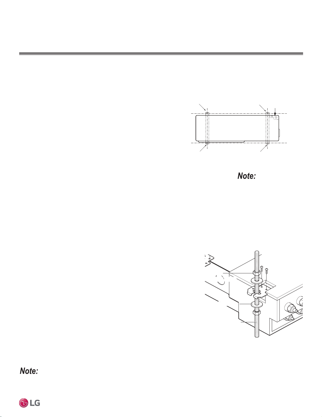
Ceiling Mount Installation - Hangers with
Hanging Bolt
1. Drill four (4) holes in the ceiling, following the dimensions on the previous page.
2. Attach the factory-supplied hangers with two (2) screws each at the designated four
(4) areas on the frame of the branch distribution unit.
3. Install an anchor in the ceiling, and attach the hanging bolts to the ceiling.
4. Add nuts and washers to the hanging bolt as shown at right.
5. Hang the branch distribution unit on the hanging bolts (ceiling side up), and after
checking for level (±5 degrees), securely tighten all nuts.
BD unit
Nu t
(M10 or M8
Nut
(M10 or M8)
Flat washerFlat washer
Hanging bol tHanging bolt
(M10 or M8)
Figure 17: Branch Distribution Ceiling Mount
Installation.
If a screw has been installed on the frame of the branch distribution unit and the screw has been removed, to prevent condensation, either re-install
the screw or cover the open hole with aluminum tape.
Ceiling Mount Installation - Hangers Only
1. Attach the factory-supplied hangers with two (2) screws each at the designated four
(4) areas on the frame of the branch distribution unit.
2. Install the branch distribution unit to the ceiling using two screws on each of the
hangers as shown below. Unit must be ±5 degrees of level.
3. Cover parts of the hanger holes with polyethylene foam insulation (to prevent con-
densation).
02817,1*$1&+25,1*7+(
287'225%5$1&+',675,%87,2181,76
Bolting the Outdoor Unit to the Platform Procedure
1. Ensure that the concrete platform will not degrade easily, and has enough
strength to bear the weight of the unit.
2. Include an H-beam support. Firmly attach the corners, otherwise the support
will bend.
3. Use a hexagon nut.
4. If there is a possibility of vibration from the outdoor unit transmitting to the
building, add an anti-vibration material to the platform.
5. Include enough space around the concrete foundation for condensate drain-
age.
6. Seal all wiring and piping access holes with field-supplied sealing material to
prevent animals and bugs from entering the unit.
Figure 18: Bolting the Outdoor Unit to the Platform (Piping
Location Will Differ Depending on Outdoor Unit Model).
Bolt
Refrigerant Pipe
Connection Location
Top of Outdoor Unit
(Looking Down)
Bolt
Bolt
Bolt
Mounting / Anchoring the Outdoor Unit General Specifications, continued.
Loading ...
Loading ...
Loading ...